1. Introduction
The durability of a PS-PVD 7YSZ thermal barrier coating on an alumina-forming Ti
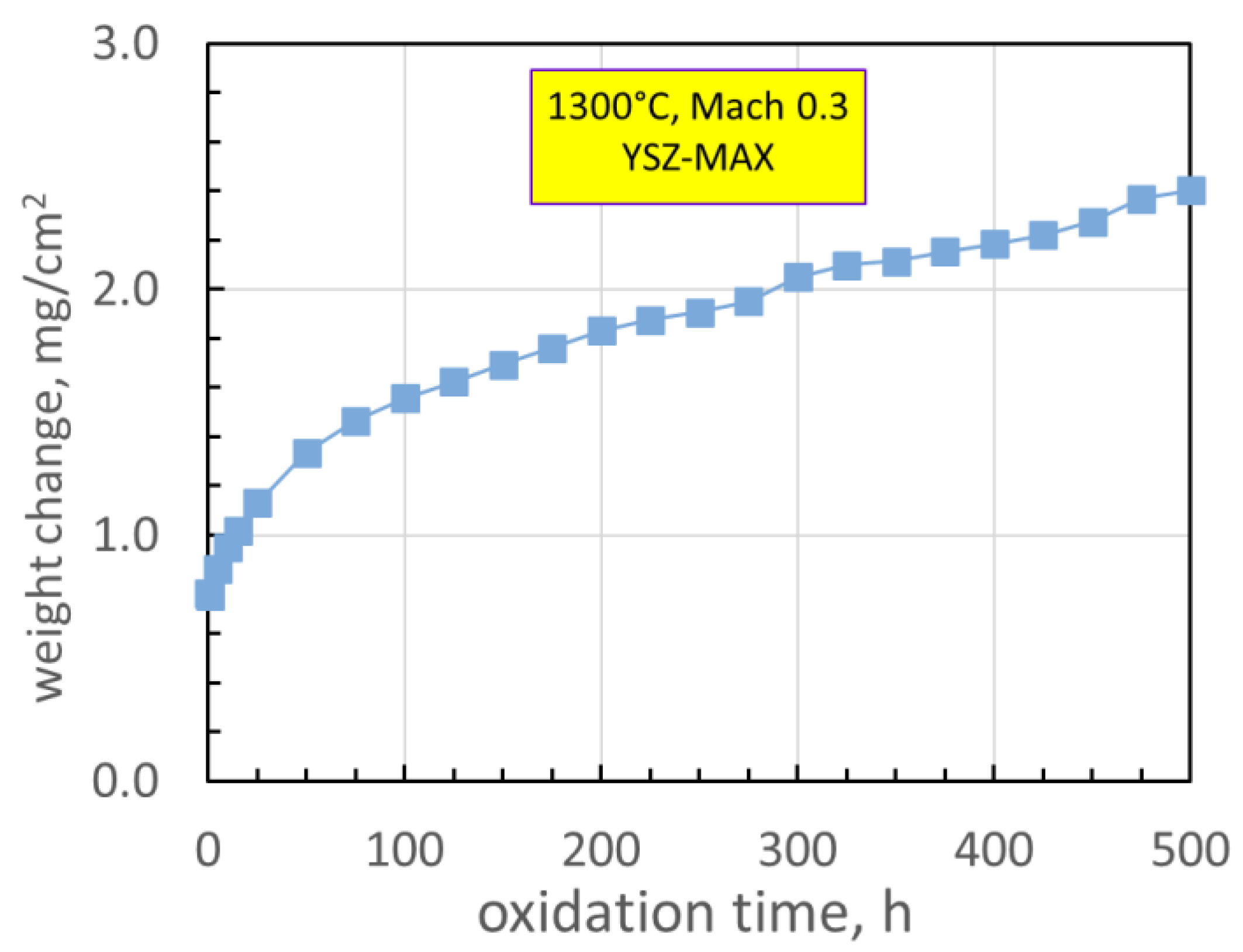
2AlC MAX phase was investigated in a high velocity Mach 0.3 (~ 100 m/s) burner test, burning Jet A fuel at atmospheric pressure. The system survived 500 h at a surface temperature of 1300°C, using 5-h cycles, with no backside cooling. The oxidation was modest, gaining just 2.4 mg/cm
2, exhibiting well-behaved cubic-linear kinetics (
Figure 1).[
1]
No indication of TBC failure or spallation was apparent. This was compared to furnace cycling of commercial TBC-Ni(Pt)Al bondcoat-superalloy systems with only 30h life projected at 1300°C, and only 7 μm of Al
2O
3 TGO growth sustained.[
2] For the 500h YSZ-MAX phase burner test, optical and SEM microstructural analyses revealed an intact 22 μm Al
2O
3 scale under the TBC at the hot gas impingement face and approximately 14 μm on the bare backside. The exposed backside was somewhat cooler and subject to scale volatility, exhibiting a filamentary, etched scale surface structure, with signs of Ti- and Al-oxide attack by moisture-induced volatilization. The frontside YSZ coating underwent sintering and some phase migration to high-Y cubic and low-Y tetragonal, as demonstrated by Rietveld XRD analyses. The expected transformation of low-Y (t) phase to the detrimental monoclinic phase, associated with TBC spallation and delamination, was not observed. The present FIB-STEM study was initiated to support and enlarge upon those microstructural and XRD phase findings, but on a much finer scale.
2. Materials and Methods
The material, coating, and burner test had been described in detail.[
3] Briefly, Kanthal/Sandvik MAXthal 211™ Ti
2AlC material was sectioned from a sintered slab and coated in the Sulzer-Oerlikon-Metco plasma spray physical vapor deposition (PS-PVD) facility at the NASA Glenn Research Center. The burner rig utilized 120 psig (800 kPa) filtered shop air and approximately 1.1 kg (2.5 lb)/min airflow, preheated and mixed with atomized Jet-A fuel. Combustor pressure was 1 psi (6.9 kPa) above ambient to produce a Mach 0.3 flame velocity through a 1 in. (2.54 cm) exit nozzle. Flame temperature was monitored by thermocouple, sample temperature by optical pyrometer (8 μm wavelength for YSZ, emissivity set at 0.92, and 2-color pyrometer for bare Ti
2AlC) controlled ±5° C by a feedback loop. The YSZ-Ti
2AlC interface was estimated as 1244°C and the bare backside was measured as 1216°C. Cycling every 5 h was produced by pivoting the burner apparatus. Inspections and weighing occurred at 1, 10, 15, 25 h, then every 25 h thereafter, as measured on an analytical balance sensitive to 0.01 mg.
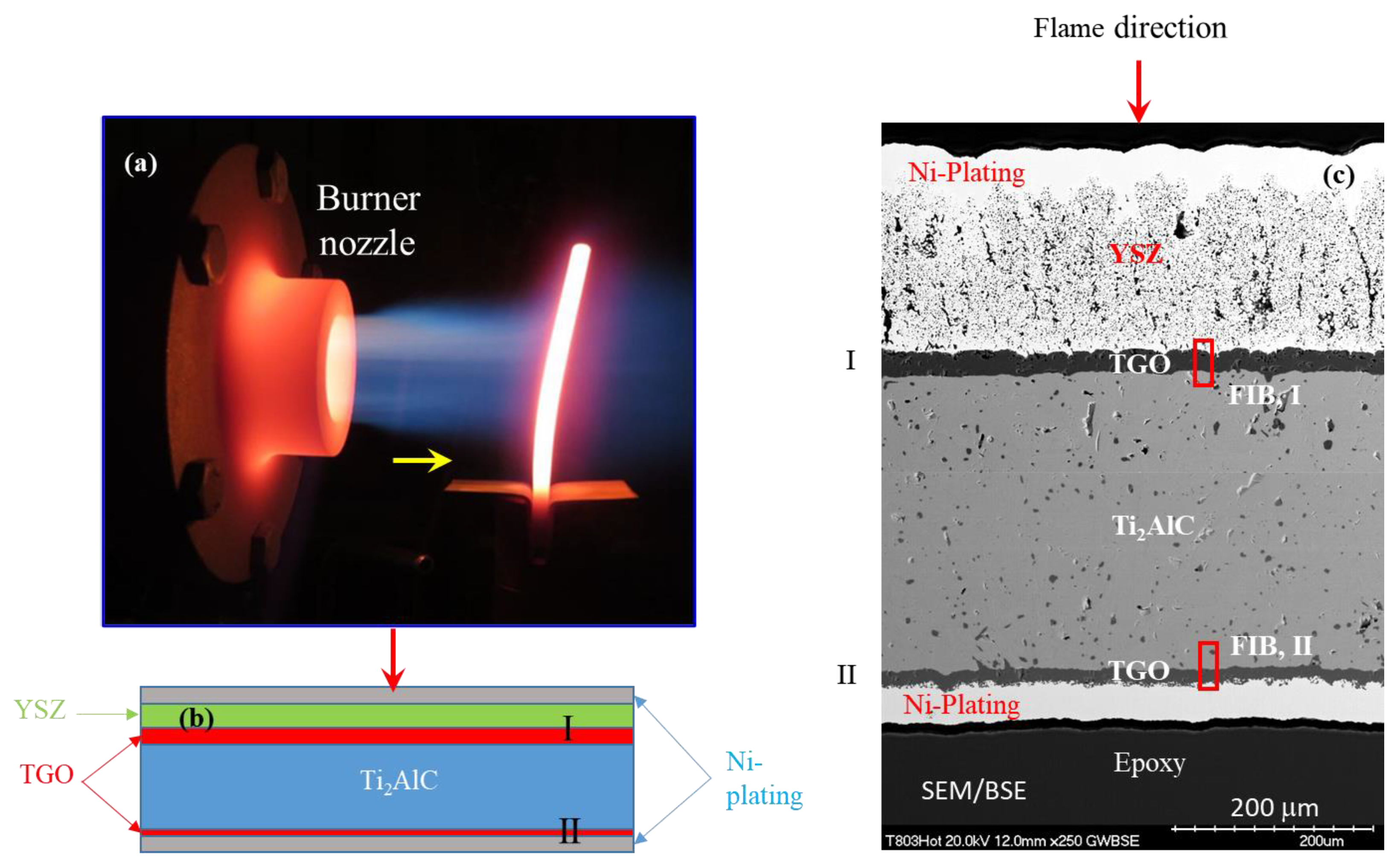
The burner and sample are shown in
Figure 2. The YSZ coating was exposed face-on (arrow) to the hot gas exhaust of the burner. The 1300°C test control coating surface temperature was targeted at the centerline of the hot zone. The schematic (2b) illustrates the arrangement of the Ni-plating, YSZ TBC top coat, Al
2O
3 scale (TGO), and Ti
2AlC substrate in the polished cross-section with respect to hot gas impingement (arrow). Finally, a montage of the full cross-section (SEM/BSE, 2c) shows actual microstructural features. The positions of the ~ 20 μm long FIB sections was across the TGO at both front and back faces, incorporating interfaces with the TBC and Ti
2AlC matrix. These site-specific sections (TEM foils) at the coated front and uncoated backside were fibbed out using a ZEISS Auriga dual Focused Ion Beam (FIB)/SEM microscope, and are marked as “FIB, I” and “FIB, II”, resp. in
Figure 2. The TEM foils were then examined in a Thermo-Fisher Talos F200S Scanning/Transmission Electron Microscope (S/TEM) for detailed microstructural, phase and chemical analyses.
3. Results
3.1. I) YSZ coated, front side
3.1.1. Overview
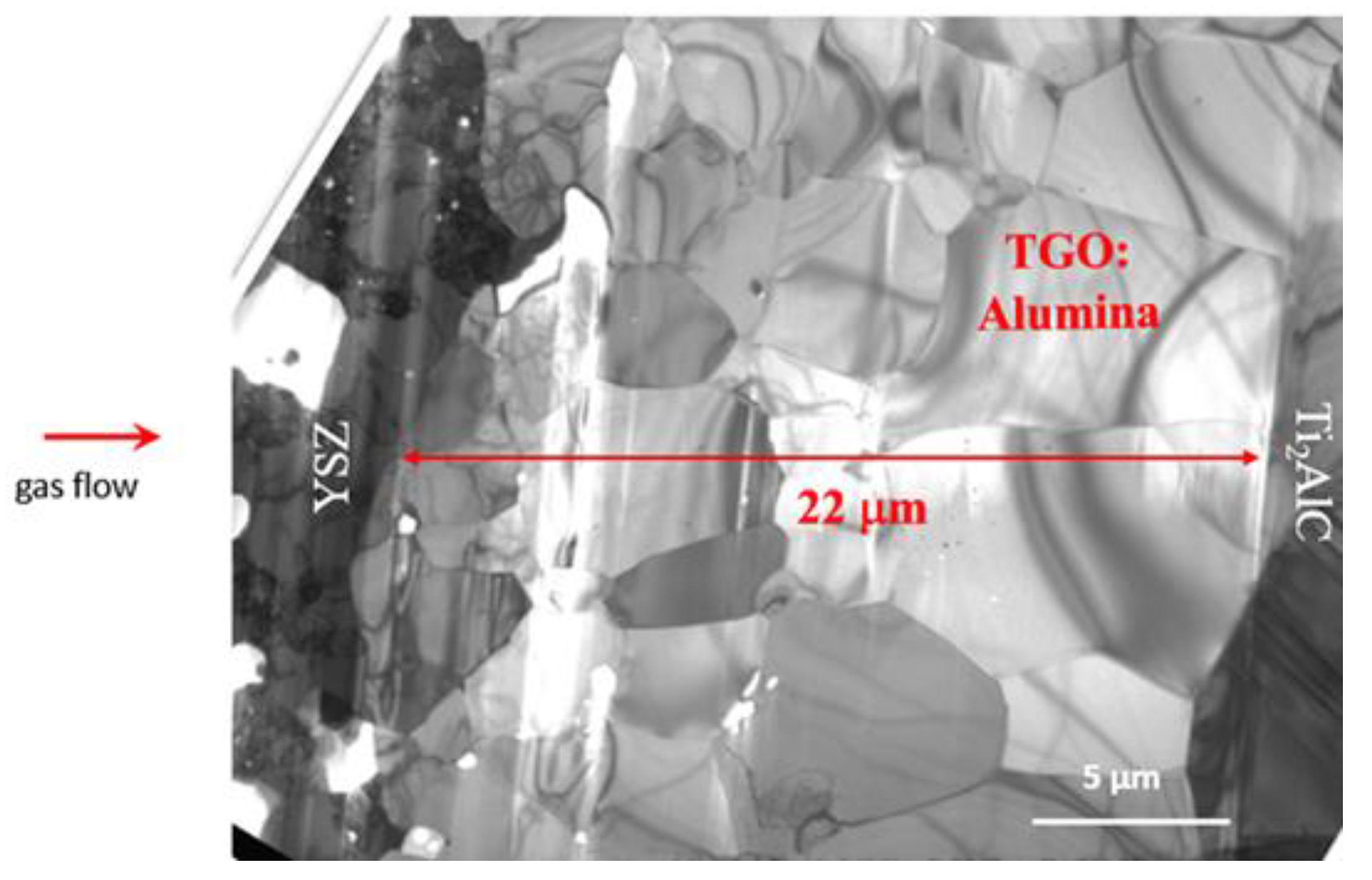
The TEM microstructure of the TBC coated side of the test bar from the interfacial region “FIB, I” marked in
Figure 2 is shown in
Figure 3. The TBC coated side of the test bar was not evenly FIB thinned over the YSZ region. Coarsened porosity was evident and heavily streaked from ion milling near the Ni-plate layer. The Al
2O
3 scale (TGO) showed typical dispersed micro-porosity toward the outer half of the scale, some associated with fine, nm-sized Ti- or Zr- rich precipitates. The Ti
2AlC was faulted, but with no dislocations observed on this hot convex side. The YSZ was a mix of large, featureless, cubic grains and smaller, heavily strained and faulted, believed to be ordered
t′′ tetragonal. The monoclinic phase was not observed. The faulted grains contained lathe shaped domains with primarily (100) boundaries, some having (110) facets. These fault arrays indicate ferro-elastic domains used to explain high toughness in the 7YSZ
t' phase.[
4] Moire' patterns from overlapping, slightly offset or rotated variants, 20-100 nm wide, were also prevalent, consistent with imaging theory. Coarsened, intergranular micro-porosity was ubiquitous. This derived from the desirable dispersed intragranular nano-porosity responsible for low thermal conductivity in PVD -type coatings. Local Fe-oxide particles, identified at the Al
2O
3 surface and in the YSZ, may indicate a processing contamination issue. Iron impurities in our PS-PVD coatings had not typically been seen before.
3.1.2. Microstructures, I. Front
The first image (
Figure 3) shows the ~ 22 μm thickness of the Al
2O
3 scale (TGO) at the front, burner side. Also present in this foil is a small amount of the adjoining YSZ of the thermal barrier coating on the left and the Ti
2AlC MAX phase substrate on the right. The alumina grains (columnar) are on the order of 5 μm wide at the Ti
2AlC interface and slightly smaller (equiaxed), ~ 3 μm, at the YSZ interface. More detail is presented in
Figure 4. The Al
2O
3 -Ti
2AlC interface is very clean and intact (4b). An array of long planar faults is apparent in a Ti
2AlC grain, reflective of the basal faulting that may occur in MAX phases to accommodate stoichiometric variations, discussed later. The image in
Figure 4a is from the central portion of the Al
2O
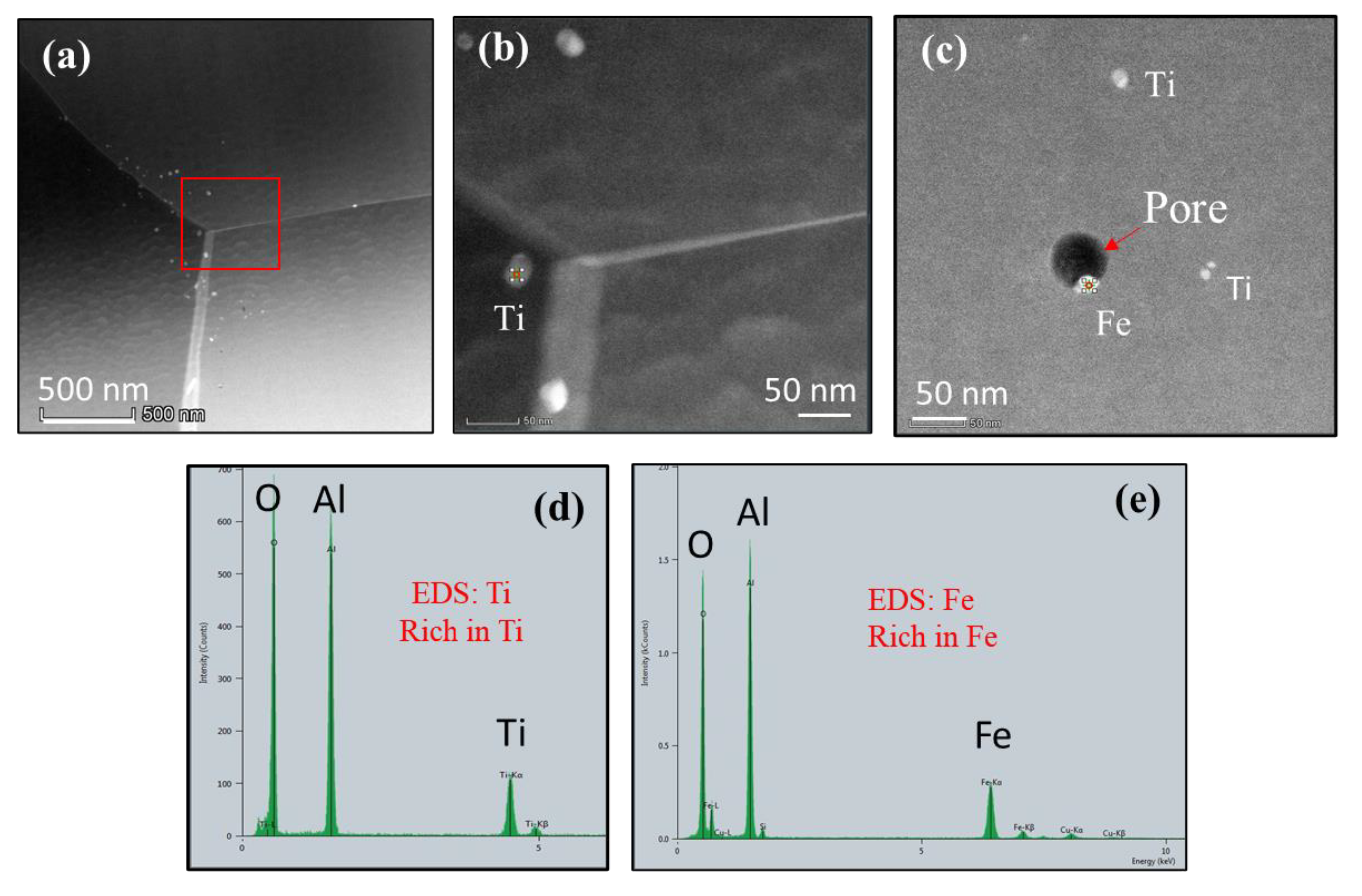
3 scale. It shows a small amount of intragranular porosity, generally finer than the intergranular pores displayed at lower magnification. Many of the pores are seen to be associated with dark nanoparticles, all quite fine on the order of 100 nm. Similar pore-metal features were observed previously for alloy oxidation and may be typical of alumina scales. The white particle in the STEM image (
Figure 5) showed high Y, Zr content (5b), with a small Fe peak, and Cu from the support grid. The Y, Zr implies some diffusion from the TBC to the internal region of the scale. By comparison, EDS analysis of the featureless scale revealed a very clean Al, O composition (5c). Additionally, occasional light grey grains in the TBC match contrast with those at the Al
2O
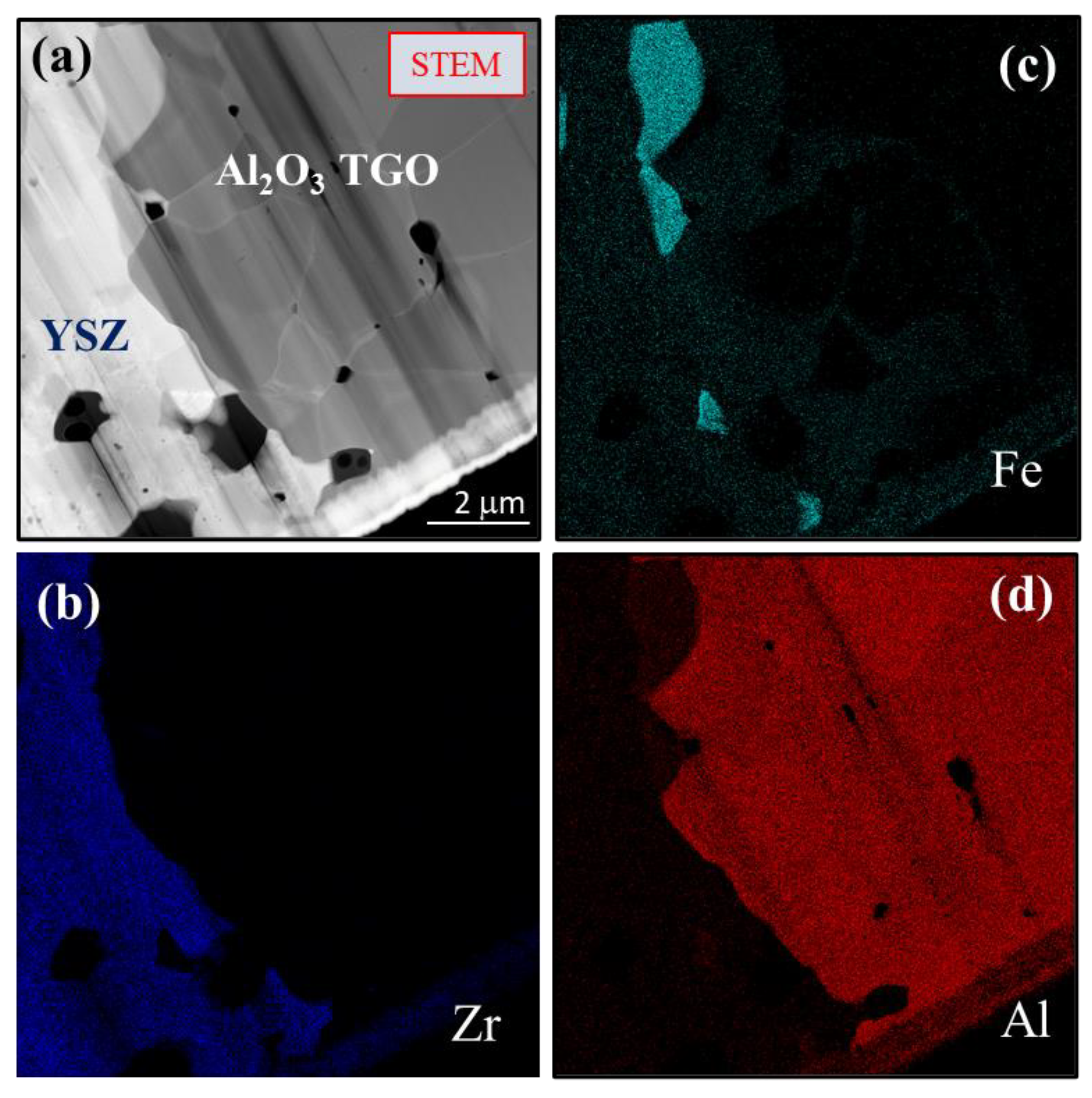
3 scale interface and are believed to be Fe-rich oxide as indicated by EDS. The TGO/YSZ interface is shown in
Figure 6 (a-d), with YSZ, Al
2O
3, and a few Fe-rich grains at the interface. These are likely iron-oxide grains formed due to spurious Fe-contamination during coating processing.
The images in
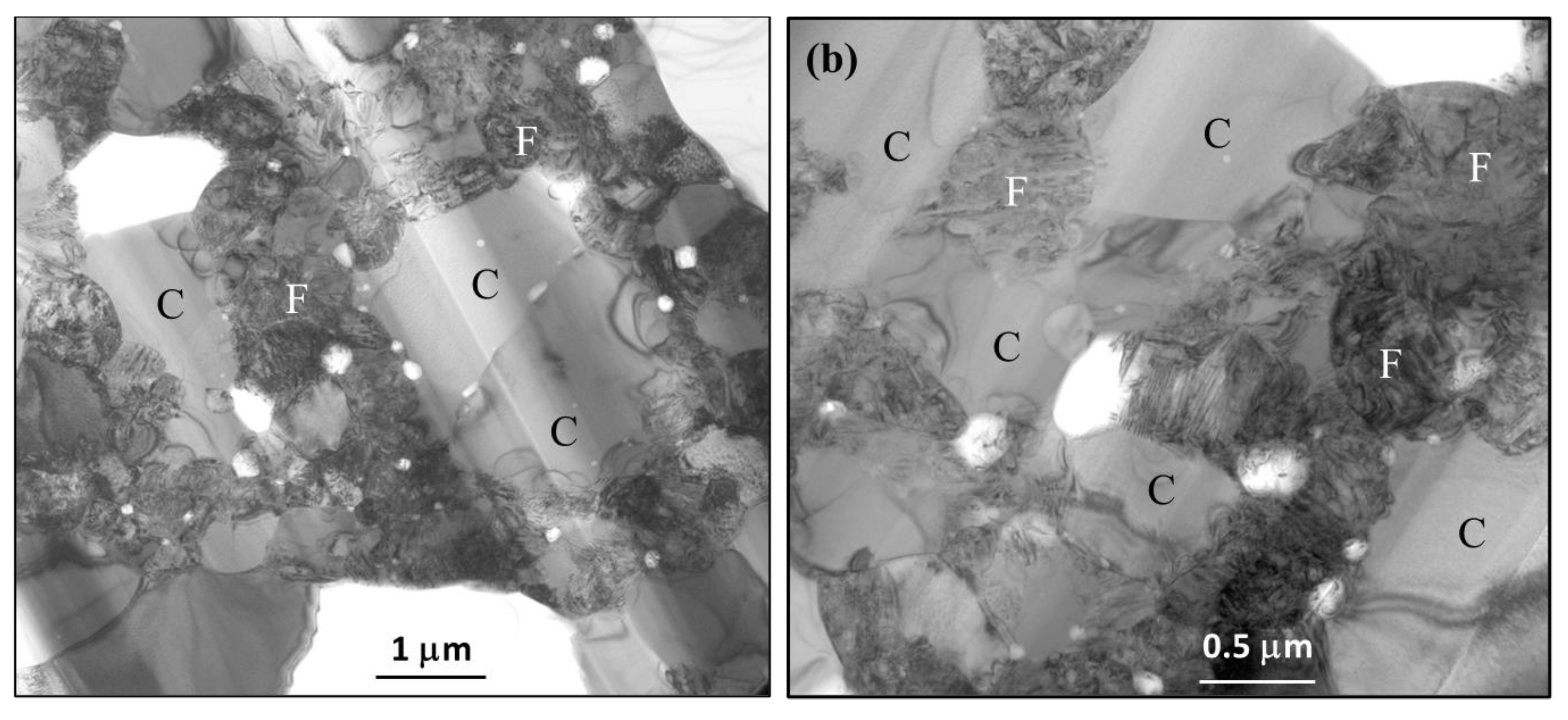
Figure 7 shows the YSZ TBC region which is generally a mosaic of 1-2 μm ‘clear’ (C) and adjacent smaller heavily faulted grains (F). The ‘feathery’ nature of the YSZ columns appears to have sintered away. Large 1-2 μm intergranular pores and finer 0.1-0.2 μm pores are prevalent. The faulted grains are also replete with a high density of strain contours, consistent with transformation stresses.
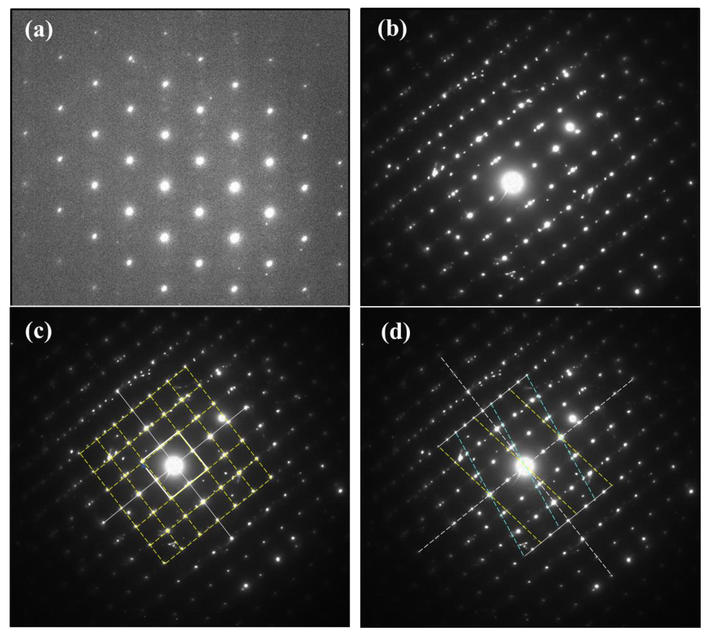
Figure 8a presents the SADP of a clean grain (C) and yields a clean cubic pattern for the ZrO
2 fluorite [110] zone axis. Since no (112) reflections are present in this zone axis, no information is obtained regarding the ordered tetragonal phases. A faulted grain (F), also produced
a ‘cubic’ [100] zone axis SADP with {100} and {110} reflections present,
Figure 8b. This zone axis also shows a multitude of additional reflections. The latter are probably related to two twinned variants of a tetragonal daughter phase with respect to the cubic parent phase.
Figure 9 presents an assemblage of lathes believed to be ferro-elastic tetragonal domains. Such arrays can minimize strain energy under stress. [
4,
5] The <100>, <110> fault planes are seen as domain boundaries, with the FFT zone axis as [100] for the central grain. Another HRTEM image,
Figure 9b, reveals multiple parallel lathes of the YSZ phase, ~ 20 nm wide. While the center lath appears featureless, the two bordering it exhibit similar cross-hatch patterns, in colonies, with some resemblance to Moire' fringes. It is speculated that similar overlapping tetragonal colonies make up these structures. Tetragonal YSZ has nearly identical a, c unit cell dimensions, but varying orientations due to oxygen ion shifts along the z-axis.[
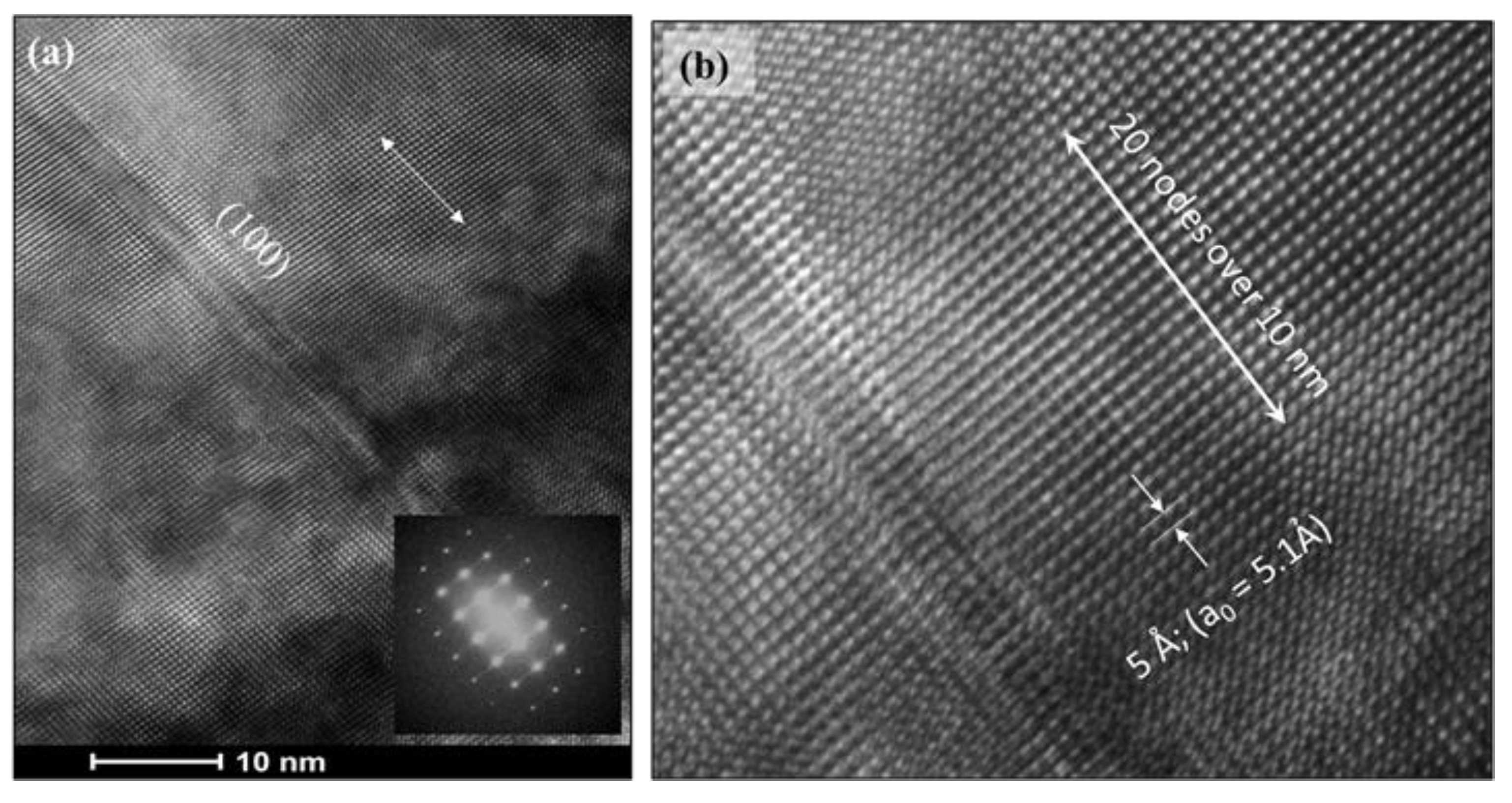
6] HRTEM images were obtained near that region and produced a nearly orthogonal lattice structure and corresponding FFT diffraction pattern. (
Figure 10) The nodes along 〈100〉,
Figure 10b, show a spacing of ~ 0.5 nm (5 Ả), approximating the unit cell dimension of 5.1 Å.
3.2. II) Uncoated, backside
3.2.1. Overview
The TEM microstructure of the uncoated backside of the test bar is from the interfacial region marked “FIB, II” in
Figure 2. Prior SEM had shown outermost filamentary, exposed alumina grains or Ti-rich scale remnants. However, this surface was not protected enough during FIB milling and appears to be just out of the span of the foil. Within the retained scale, columnar TGO Al
2O
3 grains are nicely imaged, with more equiaxed grains and porosity toward the gas surface. A small number of fine 25 nm -rich spherical particles were dispersed. Some very small Fe-rich particles were observed at the edge of 50 nm nanopores. The Al
2O
3 - Ti
2AlC interface appeared intact and exceptionally clean. No significant detachment or distress at the interface was indicated. Interface faceting followed Al
2O
3 grains. The Ti
2AlC substrate on this end (concave bending) was replete with dislocations and MAX phase stacking faults on the basal (0001) plane. The Al
2O
3 impurity phase, commonly observed as a processing artefact in Al-MAX phases, was conclusively identified by EDS.
3.2.2. Microstructures, II. Back
Figure 11 presents the uncoated backside of the Ti
2AlC sample. The Al
2O
3 TGO grew to ~ 14 μm; this was less than the front face because of the lower backside temperature of ~ 1214°C. The Al
2O
3 grains were again columnar and presented a very clean, faceted interface with Ti
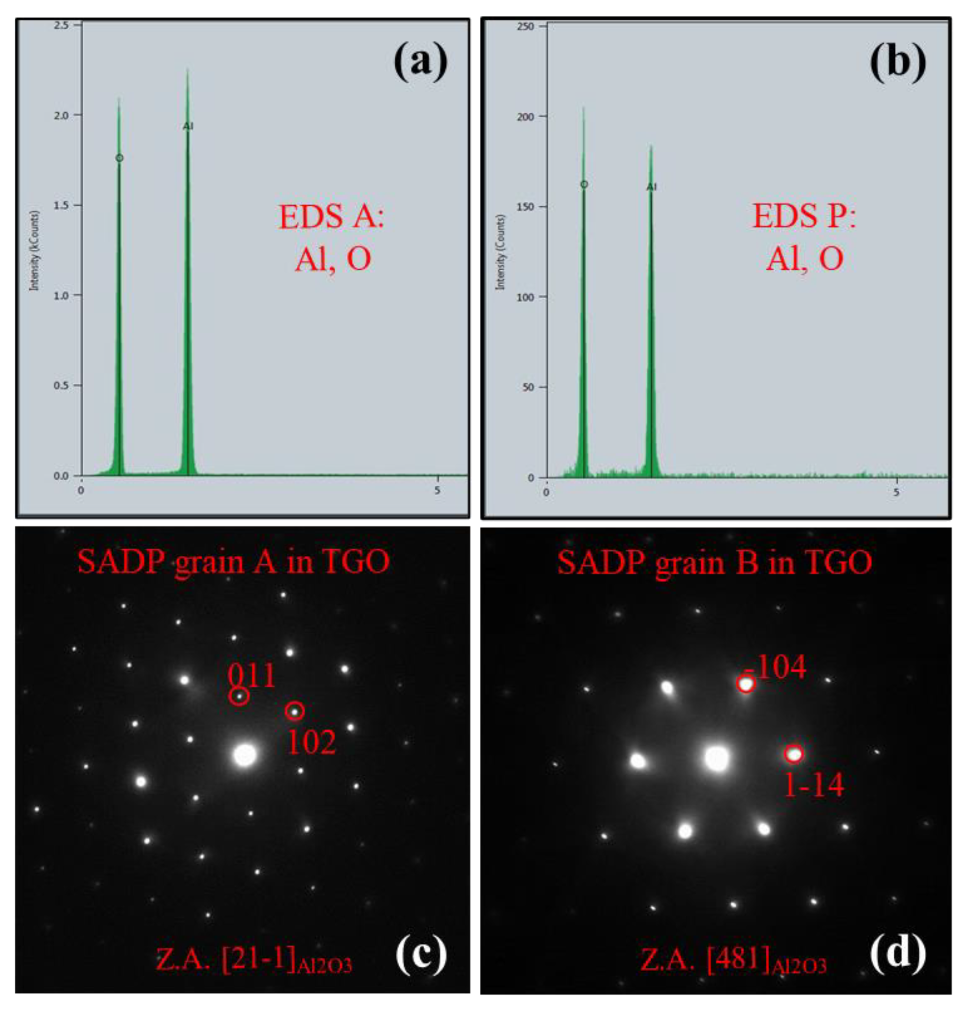
2AlC. EDS of a grain interior,
Figure 12a, shows only Al and O, as well as for a particle (P) in the MAX phase. SADP’s of the TGO (12c, d for grains marked A and B) are consistent with trigonal (pseudo-hexagonal) corundum, a=4.8 Ả, c=12.9 Ả, near Z.A. [21-1] and [48-1] respectively. The very fine nm-size TGO particles in the vicinity of the triple point in
Figure 13 a, b yield EDS showing Ti (13 d), while that (F) associated with a pore contains Fe (13 c, e).
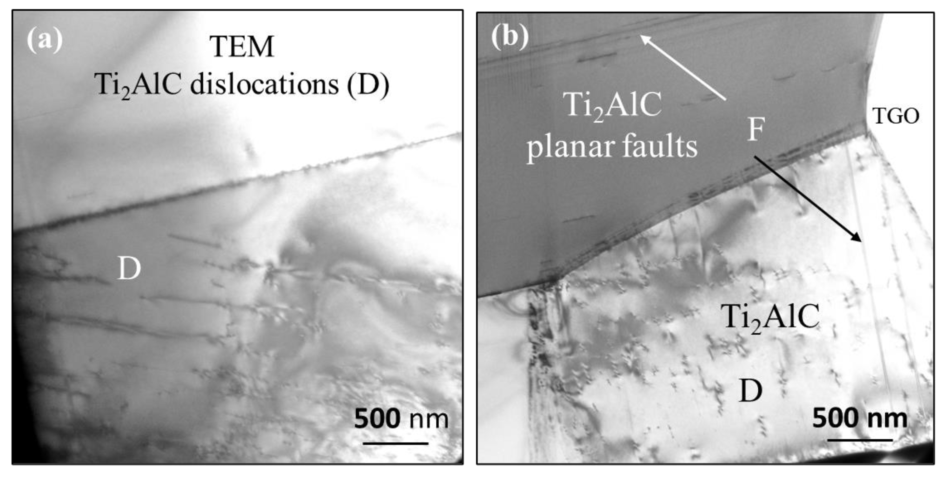
Figure 14 shows the interior of Ti
2AlC grains having a dispersion of dislocations, consistent with reported bending deformation at temperature. Other grains contain long parallel fault features,
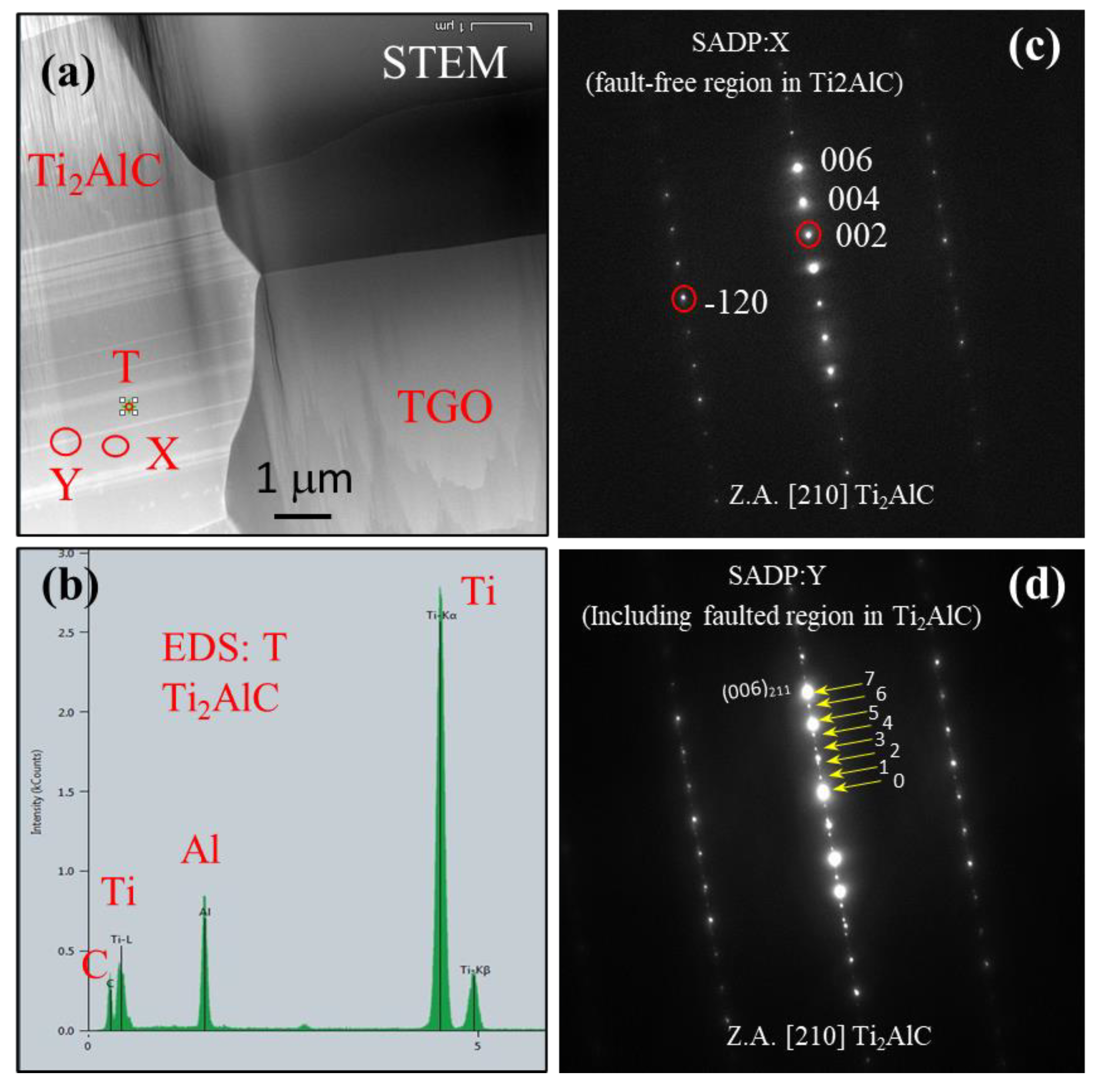
Figure 15a. The EDS spectra for Ti
2AlC (T, 15 b) again produced a clean Ti, Al, C result. Accordingly, the SADP of the grain interior (X, 15 c) shows only the Ti
2AlC hexagonal MAX phase, a= 3.1 Ả, c=13.7 Ả, Z.A. = [210]. Whereas, at faulted regions, (Y, 15 d) extra reflections appear for the basal plane along [001], presumably the fault plane. This corresponds to basal plane stacking sequence variations that can occur due to various Ti
xAl
yC
z stoichiometries. Here, the Al atoms are arranged on the c-plane, every 3
rd layer for the 211 compound, then every fourth and fifth layers for decreasing Al stoichiometries corresponding to 312 Ti
3AlC
2 and 413 Ti
4AlC
3 cells.[
7,
8] The latter are equivalent to c-plane spacings, respectively, of 4/3 and 5/3 that of the basic 3-layer cell having 211 stoichiometry. Increased d-spacings produce inversely decreased reciprocal lattice spacing. In
Figure 15d we have minor reflections produced at the fault boundary (Y), along the c-axis, with (007)
fault superposed on the (006)
211 reflection. Thus, the d-spacing is 7/6 that of the Ti
2AlC 211 phase, or has 3.5 layers/cell, midway between 211 and 312 MAX phase cells. The fault stoichiometry can therefore be surmised to be Ti
2.5AlC
1.5, or Ti
5Al
2C
3.
4. Discussion
4.1. PS-PVD YSZ TBC.
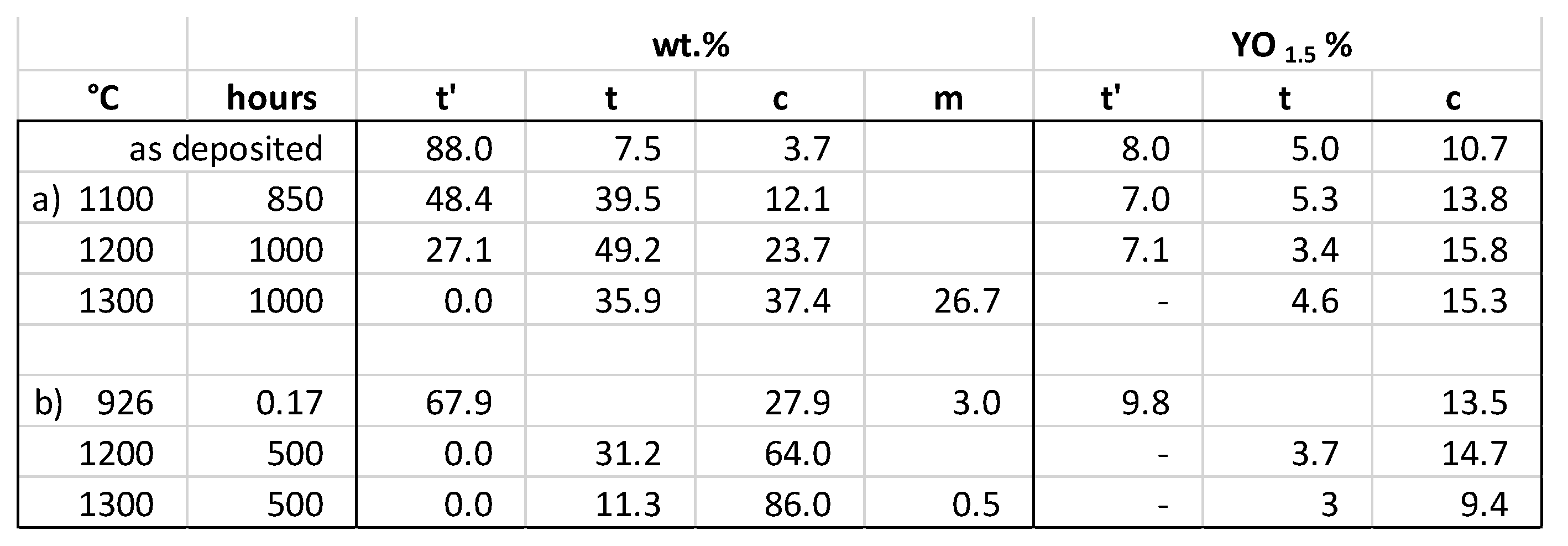
Table 1 compares the XRD phase analyses of this coating with those from an extensive annealing study by Witz, et al.,[
9] both determined from Rietveld full XRD pattern fitting. Both indicate a thermally activated transition from the quenched-in metastable
t´ tetragonal, with quenched-in Y content, into the equilibrium, low Y tetragonal (
t) + high Y cubic (
c). Those general trends were repeated from earlier studies. However, a much higher amount of cubic (28-86 % compared to 4-37%) is shown throughout for our coating, as well as almost negligible 0.5% monoclinic after aging at 1300°C. Given the TEM structures showing nearly equal amounts of cubic and faulted tetragonal grains, (
Figure 7), one can only surmise that the faulted tetragonal structures are exhibiting a cubic nature in XRD analyses. Initially, (
t) identification was based primarily on {400} peak splitting due to increased c/a. Now, the c-axis vacancy ordering that gives rise to the tetragonality appears to be occurring without a change in lattice constants. Thus, ferro-elastic domains appear in HRTEM imaging, but without the classic (400)
c peak splitting in X-ray diffraction patterns. The proximity and distribution of the ‘clear’ and faulted grains is consistent with Y partitioning and phase separation.
The Y content in the various phases was estimated from Rietveld lattice parameters and calibration formulas from the literature. The results based on a c/a calibration are also shown in
Table 1. The present coating is seen to have higher as-sprayed YO
1.5 content in the cubic phase compared to that of Witz et al. (n. the 926°C/0.17 h condition here is considered to be essentially as-sprayed). The cubic results from the two studies are similar after 1100°C and 1200°C exposures, at 13-15%, but lower here after 1300°C, at 9% vs 15%.
According to the study by Azzopardi, et al., 2004, [
10] for PVD t´ YSZ coatings, the initial metastable tetragonal
t′ phase transforms into a mixture of yttria-poor tetragonal phase
t and yttria-rich cubic
c phase upon thermal aging, as described previously over many years. However, on cooling, the
c phase can further transform into an yttria-rich
t′′ phase[
11] that has tetragonal symmetry but cubic dimensionality. The yttria-poor
t phase does not transform to monoclinic, presumably because of the fine grain size and stress constraints on the transformation. That
t phase should not be considered ‘non-transformable
t′, e.g., upon grinding. To make matters more complex, these
t + c phases evolved into a fine, 10 nm banded domain structure.
It is therefore postulated that the present study exhibits faulted t′′ YSZ grains, transformed from cubic parent grains on cooling. A domain structure reflects the three different tetragonal variants possible from a cubic parent, usually shown by dark field imaging using the (112) extra spots. Here they are shown as domain boundaries in HRTEM, with a node spacing of 5 Ả. But the low Y content (9%) is more representative of t′′ rather than equilibrium phase-separated cubic. Martensite has not formed due to the small grain size of any parent structures and was not obvious in the TEM microstructures or previous XRD. The ‘clear’ cubic grains have retained the equilibrium c structure. Further subtleties and delineations are beyond the scope of this work. The presence of these domains, even after extensive thermal exposure, probably contributes to the overall mechanical durability of the coating upon cycling, as does the absence of the disruptive monoclinic transformation.
4.2. Al2O3 TGO.
The alumina scales exhibited typical inner columnar grains and more equiaxed outer grains. At the frontside YSZ interface, some Fe-rich scales were observed and presumed to result from some Fe-rich chamber contamination during the initial plasma spray conditions, before deposition. None were seen on the backside. Small included Zr(Y) particles were observed underneath the YSZ coating. Intergranular porosity was present in the equiaxed region, but absent in the columnar region. The interior of the grains was essentially featureless, except for minute amounts of fine, 25-50 nm pores and Fe, or Ti-rich particles. Again, the source of the Fe is believed to be migration from initial PSD-PVD contaminants, whereas the Ti indicates some minute presence from the Ti
2AlC substrate. Considering the 2:1 Ti:Al ratio in the 211 MAX phase, it is remarkable that only this small amount of Ti enters into the scale. This is thought to be a vestige of initial Ti-rich transient oxidation before a healing layer of Al
2O
3 is formed. Oxidation of bare Ti
2AlC in high temperature air or oxygen is well known to produce a TiO
2 or TiAl
2O
4 initial scale before a healing, rate-controlling scale of Al
2O
3 is formed underneath. The exclusion of the typical TiO
2 transient outer layers here suggests that low pO
2 pre-oxidation, expected during initial PS-PVD processing, plays a beneficial role here. The stable, long-term growth of Al
2O
3 at 1300°C is confirmed by the chemical and phase purity of the scale at the Ti
2AlC interface. The Al
2O
3 -Ti
2AlC interfacial regions appeared fully intact, smooth, and atomically bonded. (Unfortunately, the filamentary Al
2O
3 TGO surface resulting from scale volatility on the exposed backside [
1] was not included in the optimal portion of this FIB section).
4.3. Ti2AlC substrate.
The MAX phase substrate was fine grained, exhibited a typical Al
2O
3 processing inclusion, but little chemical/phase diversity. Planar, intragranular (basal plane) faults were common, often nearly perpendicular to the Al
2O
3 -Ti
2AlC interface. These are interpreted as a tendency toward local Ti
3AlC
2 chemistry to accommodate reduced Al content. This mechanism allows for maintaining an intact MAX phase – alumina interface without a distinct depletion layer, as is common for alumina-forming alloys or Cr
2AlC. It is perhaps an indication of the ability of the Ti
xAlC
y MAX phases to supply Al rapidly enough through bulk of the substrate along basal planes to support the growing scale. Preferential Al diffusion along basal planes has been proposed to explain preferential Al
2O
3 scale formation and improved oxidation behavior for textured Ti
2AlC, Ti
3AlC
2, and Ti
3(Si,Al)C
2 MAX phases.[
12,
13,
14,
15] Here MAX phase basal planes were aligned perpendicular to the hot pressing direction and served to enhance Al diffusion toward side faces (TSS) in comparison to top faces (TTS). The present SADP diffraction results along [001] on a basal plane fault (
Figure 15) suggest a fault stoichiometry of Ti
2.5AlC
1.5. Dislocations were also evident as an indication of the macroscopic plastic deformation that occurred in this sample progressively throughout the 500h test. That was manifested as a 2.3 mm cord-wise deflection across the 6.8 cm burner sample length, as bent by the gas flow. [
3] Dislocations and plastic deformation are consistent with high creep rates reported for MAX phase structures above 1200°C.[
16]
5. Summary
A Ti2AlC MAX phase substrate was coated on one side with a 7YSZ TBC by PS-PVD. The sample was oxidized in a Mach 0.3 burner rig at a 1300°C surface temperature for 500 h with no indication of scale or TBC failure. FIB/STEM samples of the intact Al2O3 TGO were obtained at the coated front and bare backside. The YSZ was a mix of 1-2 μm ‘clean’ and 0.5-1 μm ‘faulted’ grains with nm-size domains. The domains produced complex SADP; HRTEM revealed {100} and {110} domain boundaries; while XRD had identified primarily ‘cubic cell’ structures. These ferro-elastic domains are believed to represent high Y, tetragonal t′′ YSZ variants generated from the cubic phase on cooldown. No martensite was observed, presumably due to mechanical constraints of fine grain size. The complexity of aged YSZ coatings is a topic requiring intensive study to be fully conclusive. The presence here of ferro-elastic t′′ domains are expected to be beneficial, in the same manner as those widely documented in metastable, ‘non-transformable,’ as-sprayed t′ tetragonal domains. Still, the thermal expansion matching of this YSZ-TGO-MAX phase system presents the largest positive factor for long term, high temperature, cyclic durability. The loss of the strain compliant, PVD ‘feather’ grain structure during sintering, useful for TBC’s on superalloys operated at lower temperatures, has apparently not diminished this durability.
The TGO was essentially α-Al2O3, with a duplex structure of outer ~ 0.3 μm equiaxed grains (with intergranular porosity) and inner columnar 0.5 μm grains. The latter showed minimal entrapped fine 25-50 nm porosity and Zr(Y), Fe, or Ti-rich particles. Little interaction with the YSZ was observed. Unfortunately, no information was obtained at the bare backside scale-gas interface because it was outside the span of the FIB section. That surface had exhibited volatility issues (grain boundary etching, filamentary α-Al2O3, TiO2 removal) in previous SEM studies.
The scale maintained a perfectly intact interface with the Ti2AlC substrate, with no evidence of interfacial porosity or chemical/phase variations. The Ti2AlC substrate exhibited no depletion zone, but rather numerous crystallographic faults along the basal plane of the hexagonal structure, often in a perpendicular orientation to the interface, extending deep into the grains. These are believed to offer a means of depleting Al by forming a crystallographic planar defect having lower Al stoichiometry in the hexagonal stacking of the Tin+1AlCn MAX phase series. This has wide implications for Al depletion mechanisms in the high temperature oxidation of Tin+1AlCn family of MAX phases.
Author contributions: J. Smialek conceived and organized the research, prepared the manuscript; A. Garg performed the transmission electron microscopy; B. Harder produced the coated sample; M. Cuy performed the high velocity burner rig test.
Funding
These studies were supported by the NASA Fundamental Aeronautics Program.
Acknowledgements
The authors gratefully acknowledge Wayne Jennings for producing the FIB sections.
Conflicts of Interest
The authors declare no conflict of interest.
References
- J.L. Smialek, M.D. Cuy, B.J. Harder, A. Garg, R.B. Rogers, Durability of YSZ coated Ti2AlC in 1300°C high velocity burner rig tests, J. Am. Ceram. Soc. 103 (2020) 7014–7030. [CrossRef]
- J.L. Smialek, Compiled furnace cyclic lives of EB-PVD thermal barrier coatings, Surf. {&} Coatings Technol. 276 (2015) 31–38. [CrossRef]
- J.L. Smialek, M.D. Cuy, B.J. Harder, A. Garg, R.B. Rogers, Durability of YSZ Coated Ti2AlC in 1300°C Mach 0.3 Burner Rig Tests; NASA/TM-2020-220380, (2020).
- A.V. Virkar, R.L.K. Matsumoto, Ferroelastic Domain Switching as a Toughening Mechanism in Tetragonal Zirconia, J. Amer. Ceram. Soc. 69 (1986) C224--C226. [CrossRef]
- G. Srinivasen, J.F. Jeu, S.Y. Kuo, A.V. Virkar, Ferroelastic Domain Switching in Polydomain Tetragonal Zirconia Single Crystals, J. Am. Ceram. Soc. 72 (1989) 2098–2103. [CrossRef]
- R.A. Miller, J.L. Smialek, R.G. Garlick, Phase stability in plasma-sprayed, partially stabilized zirconia-yttria, Adv. Ceram. • Vol. 3, Sci. Technol. ZIRCONIA. 3 (1981) 241–253.
- M. Radovic, M.W. Barsoum, MAX phases: Bridging the gap between metals and ceramics, Am. Ceram. Soc. Bull. 92 (2013) 20–27.
- M.W. Barsoum, T. El-raghy, The MAX Phases : Unique New Carbide and Nitride Materials, Am. Sci. 89 (2001) 334–343.
- G. Witz, V. Shklover, W. Steurer, S. Bachegowda, H.P. Bossmann, Phase evolution in yttria-stabilized zirconia thermal barrier coatings studied by rietveld refinement of X-ray powder diffraction patterns, J. Am. Ceram. Soc. 90 (2007) 2935–2940. [CrossRef]
- A. Azzopardi, R. Mevrel, B. Saint-Ramond, E. Olson, K. Stiller, Influence of aging on structure and thermal conductivity of Y-PSZ and Y-FSZ EB-PVD coatings, Surf. Coatings Technol. 177–178 (2004) 131–139.
- M. Yashima, M. Kakihana, M. Yoshimura, Metastable-stable phase diagrams in the zirconia-containing systems utilized in solid-oxide fuel cell applcation, Solid State Ionics. 86–88 (1996) 1131–1149.
- L. Xu, D. Zhu, Y. Liu, T.S. Suzuki, B. Kim, Y. Sakka, S. Grasso, C. Hu, Effect of texture on oxidation resistance of Ti3AlC2, J. Eur. Ceram. Soc. 38 (2018) 3417–3423.
- X. Li, X. Xie, J. Gonzalez-Julian, J. Malzbender, R. Yang, Mechanical and oxidation behavior of textured Ti2AlC and Ti3AlC2 MAX phase materials, J. Eur. Ceram. Soc. 40 (2020) 5258–5271. [CrossRef]
- X. Li, X. Xie, J. Gonzalez-julian, R. Yang, R. Schwaiger, Oxidation and creep behavior of textured Ti2AlC and Ti3AlC2, J. Eur. Ceram. Soc. 42 (2022) 364–375. [CrossRef]
- G. He, X. Zhang, W. Wang, K. Ma, J. Zuo, M. Li, C. Liu, J. Xu, Anisotropy oxidation behavior and mechanism of textured Ti3(Si,Al)C2 ceramic, Nat. Mater. Degrad. 3 (2023) 1–11. [CrossRef]
- Z.M. Sun, Progress in research and development on MAX phases: a family of layered ternary compounds, Int. Mater. Rev. 56 (2011) 143–166. [CrossRef]
Figure 1.
Weight change performance of YSZ-coated Ti2AlC MAX phase in 1300°C Mach 0.3 burner test. (from Smialek et al., 2020).
Figure 1.
Weight change performance of YSZ-coated Ti2AlC MAX phase in 1300°C Mach 0.3 burner test. (from Smialek et al., 2020).
Figure 2.
Orientation of FIB samples at (I) front and (II) back sides of sample. a) photograph of burner operation showing front side flame impingement. b) schematic of sample cross-section. c) montage of SEM/BSE cross-section images of sample and scale showing TBC coated front side (I) and bare backside (II) after 500 h burner rig test at 1300°C. his is a figure. Schemes follow the same formatting.
Figure 3.
TEM Overview of the front side, FIB section I: TBC on left, Ti2AlC MAX phase on right. Avg. scale thickness from prior SEM study was 22 μm, as shown. (500 h at 1300°C).
Figure 3.
TEM Overview of the front side, FIB section I: TBC on left, Ti2AlC MAX phase on right. Avg. scale thickness from prior SEM study was 22 μm, as shown. (500 h at 1300°C).
Figure 4.
Features in Al2O3 TGO (I): a) fine 50 nm, dispersed intragranular porosity (light) and particles (dark) in Al2O3 grains near TBC; b) clean, intact Al2O3/Ti2AlC interface (dashed red line) and 20 closely spaced, highly aligned linear faults in Ti2AlC grain.
Figure 4.
Features in Al2O3 TGO (I): a) fine 50 nm, dispersed intragranular porosity (light) and particles (dark) in Al2O3 grains near TBC; b) clean, intact Al2O3/Ti2AlC interface (dashed red line) and 20 closely spaced, highly aligned linear faults in Ti2AlC grain.
Figure 5.
STEM image and EDS of Zr(Y) rich particle embedded in Al2O3 (I) grain compared to clear Al2O3 region.
Figure 5.
STEM image and EDS of Zr(Y) rich particle embedded in Al2O3 (I) grain compared to clear Al2O3 region.
Figure 6.
STEM image (a) of the TBC/TGO interface (I): elemental rasters (b-d) show Fe-rich particles at interface. (500 h at 1300°C).
Figure 6.
STEM image (a) of the TBC/TGO interface (I): elemental rasters (b-d) show Fe-rich particles at interface. (500 h at 1300°C).
Figure 7.
TEM image of cubic clear (C) and tetragonal ‘faulted’ (F) submicron YSZ grains in the TBC.
Figure 7.
TEM image of cubic clear (C) and tetragonal ‘faulted’ (F) submicron YSZ grains in the TBC.
Figure 8.
SADP’s of clear (C) [100] and faulted (F) [100] YSZ grains (
Figure 7a, b), the latter showing many extra reflections probably related to variants of t´ domain orientation. Here, the primary ‘cubic’ [100] Z.A. reflections are delineated by the 3x3 dashed line grid construction (7c). Extra reflections appear to arise from two twin variants (7d), marked by yellow and aqua grid, slightly off-zone. The trace of possible twin habit planes shown as orthogonal [002] and [020] axes. (a
0 for YSZ is 5.1 Ả for the cubic parent phase and indistinguishable from tetragonal). (The tetragonal structure would, however, allow for forbidden {112} reflections in otherwise cubic patterns due to oxygen ordering along the z-axis).
Figure 9.
HRTEM images of ferroelastic domain boundaries in faulted (F) grains. b) with Z.A. = [100]; inset: fast Fourier transform of lattice image. Domain boundaries exhibit {100} and {110} nature with 45° or 90° angles of inclination between themselves. b) other domains to the left of (a).
Figure 9.
HRTEM images of ferroelastic domain boundaries in faulted (F) grains. b) with Z.A. = [100]; inset: fast Fourier transform of lattice image. Domain boundaries exhibit {100} and {110} nature with 45° or 90° angles of inclination between themselves. b) other domains to the left of (a).
Figure 10.
HRTEM images of domain boundary above
Figure 9a; (a) inset: fast Fourier transform of lattice image. (b) enlargement showing node spacing of 5 Ả, corresponding to 5.1 Ả lattice spacing for {100} planes. .
Figure 10.
HRTEM images of domain boundary above
Figure 9a; (a) inset: fast Fourier transform of lattice image. (b) enlargement showing node spacing of 5 Ả, corresponding to 5.1 Ả lattice spacing for {100} planes. .
Figure 11.
FIB section II: (a) TEM / (b) STEM images of backside of burner sample. Clean, intact Ti2AlC - Al2O3 interface. Columnar TGO grains at interface and equiaxed at gas side; planar faults (F) and included Al2O3 particle (P) in Ti2AlC. (500 h at 1300°C).
Figure 11.
FIB section II: (a) TEM / (b) STEM images of backside of burner sample. Clean, intact Ti2AlC - Al2O3 interface. Columnar TGO grains at interface and equiaxed at gas side; planar faults (F) and included Al2O3 particle (P) in Ti2AlC. (500 h at 1300°C).
Figure 12.
EDS spectra of TGO grain (A) and imbedded particle (P) in
Figure 11. hkl [21-1] and [481] Z.A. SADP of TGO grains (A) and (B) in
Figure 11. Hexagonal Al
2O
3 : a
0 = 4.8Å, c = 12.9Å.
Figure 12.
EDS spectra of TGO grain (A) and imbedded particle (P) in
Figure 11. hkl [21-1] and [481] Z.A. SADP of TGO grains (A) and (B) in
Figure 11. Hexagonal Al
2O
3 : a
0 = 4.8Å, c = 12.9Å.
Figure 13.
Al
2O
3 TGO triple point region marked O in
Figure 11b showing fine ~25 nm Ti- and Fe-rich particles in grains, (a) - (c). EDS spectra of Ti (d) and Fe (e) particles.
Figure 13.
Al
2O
3 TGO triple point region marked O in
Figure 11b showing fine ~25 nm Ti- and Fe-rich particles in grains, (a) - (c). EDS spectra of Ti (d) and Fe (e) particles.
Figure 14.
Ti2AlC grains with planar faults (F) and irregular dislocations (D).
Figure 14.
Ti2AlC grains with planar faults (F) and irregular dislocations (D).
Figure 15.
STEM image showing (a) the clean, intact Ti2AlC - Al2O3 interface; (b) EDS of the Ti2AlC phase (T); (c) ‘clean’ [210] Z.A. SADP of the fault-free region (X); and (d) extra spots in SADP of the faulted plane (Y). Ti2AlC: Hexagonal, a0 = 3.1 Å, c =1 3.7 Å. The fine spots are regularly spaced at 1/7 (006), indicating a d-spacing of 7/6 d(001).
Table 1.
Summary of YSZ coating phases after various thermal aging treatments. Rietveld
XRD full pattern fitting of for t´, t, c, and m YSZ (wt. %), with corresponding compositions (YO1.5
%): a) from Witz et al., APS. b) this study, PS-PVD.
Table 1.
Summary of YSZ coating phases after various thermal aging treatments. Rietveld
XRD full pattern fitting of for t´, t, c, and m YSZ (wt. %), with corresponding compositions (YO1.5
%): a) from Witz et al., APS. b) this study, PS-PVD.
|
Disclaimer/Publisher’s Note: The statements, opinions and data contained in all publications are solely those of the individual author(s) and contributor(s) and not of MDPI and/or the editor(s). MDPI and/or the editor(s) disclaim responsibility for any injury to people or property resulting from any ideas, methods, instructions or products referred to in the content. |
© 2023 by the authors. Licensee MDPI, Basel, Switzerland. This article is an open access article distributed under the terms and conditions of the Creative Commons Attribution (CC BY) license (http://creativecommons.org/licenses/by/4.0/).
