Submitted:
10 April 2023
Posted:
11 April 2023
You are already at the latest version
Abstract
Keywords:
1. Introduction
- incompletely restrained positioning mechanism or underconstrained CDPR. These type of CDPR can only reach equilibrium with gravity or a given force, and often cannot work with arbitrary external wrenches.
- kinematically fully constrained CDPR. The robot is completely limited in terms of kinematics, but the equilibrium equation still depends on gravity or other forces. That is to say, the robot can only work with a specific set of forces.
- completely restrained positioning mechanisms or fully constrained CDPR. The end-effector poses can be determined entirely through the cables. The limits of the end-effector movements and the wrenches acting on the end-effector depend on the cable tension limits.
- redundantly restrained positioning mechanisms or over constrained CDPR. The robot is constrained redundancy and wrenches must be distributed by cables. The number of kinematic constraints is greater than the number of DOFs so the static equilibrium of CDPR can have many solutions.
2. System description
2.1. Workspace limitations
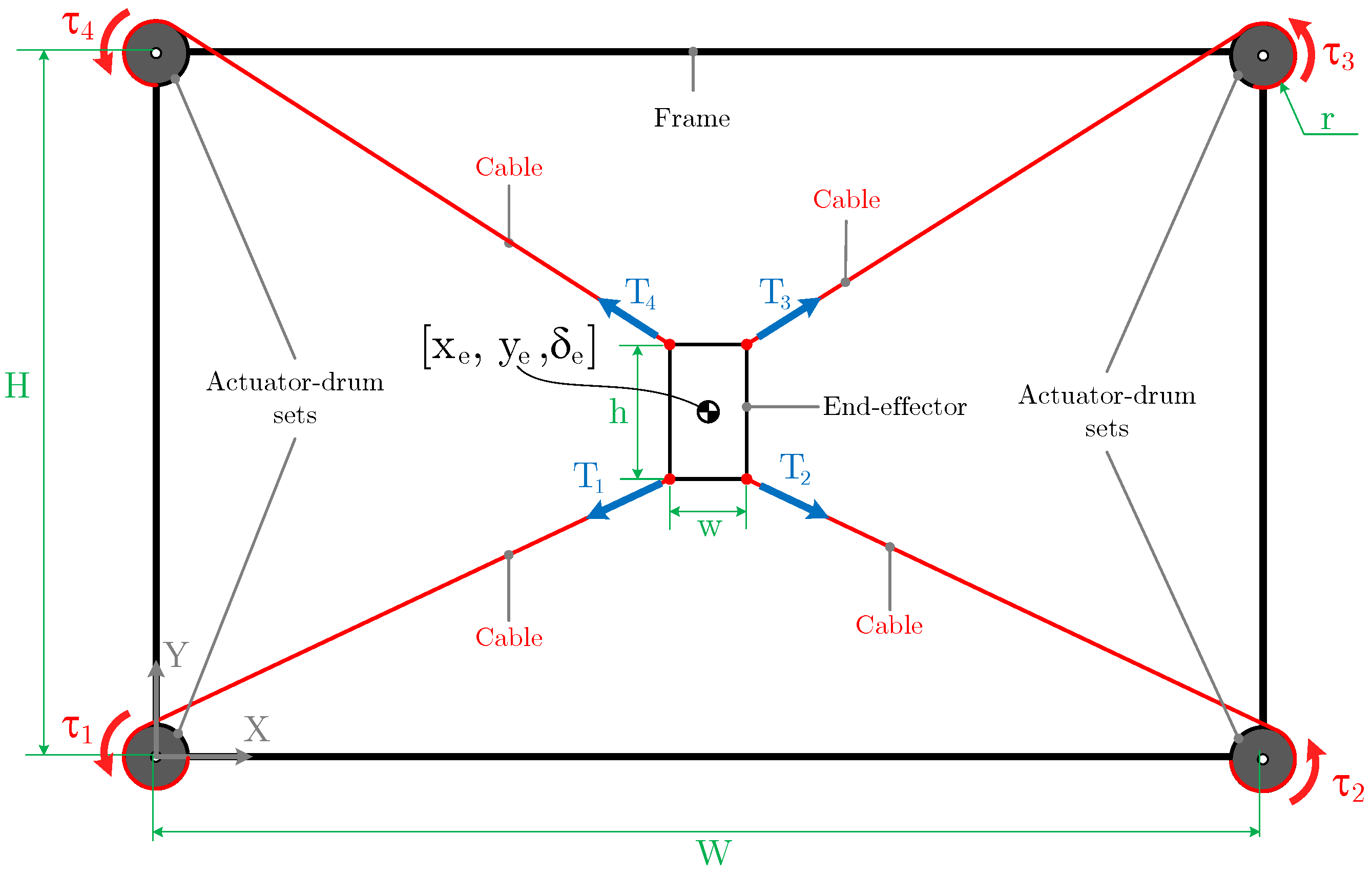
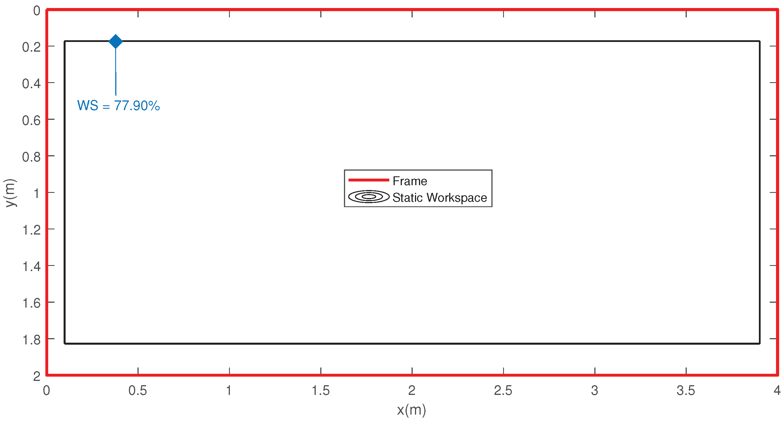
- H and W are the height and width of the frame, respectively.
- h and w are the height and width of the end-effector, respectively.
- for the tension of the cables.
- for the torques exerted by each motor.
- r the effective radius of the drums.
- the coordinates of the end-effector.
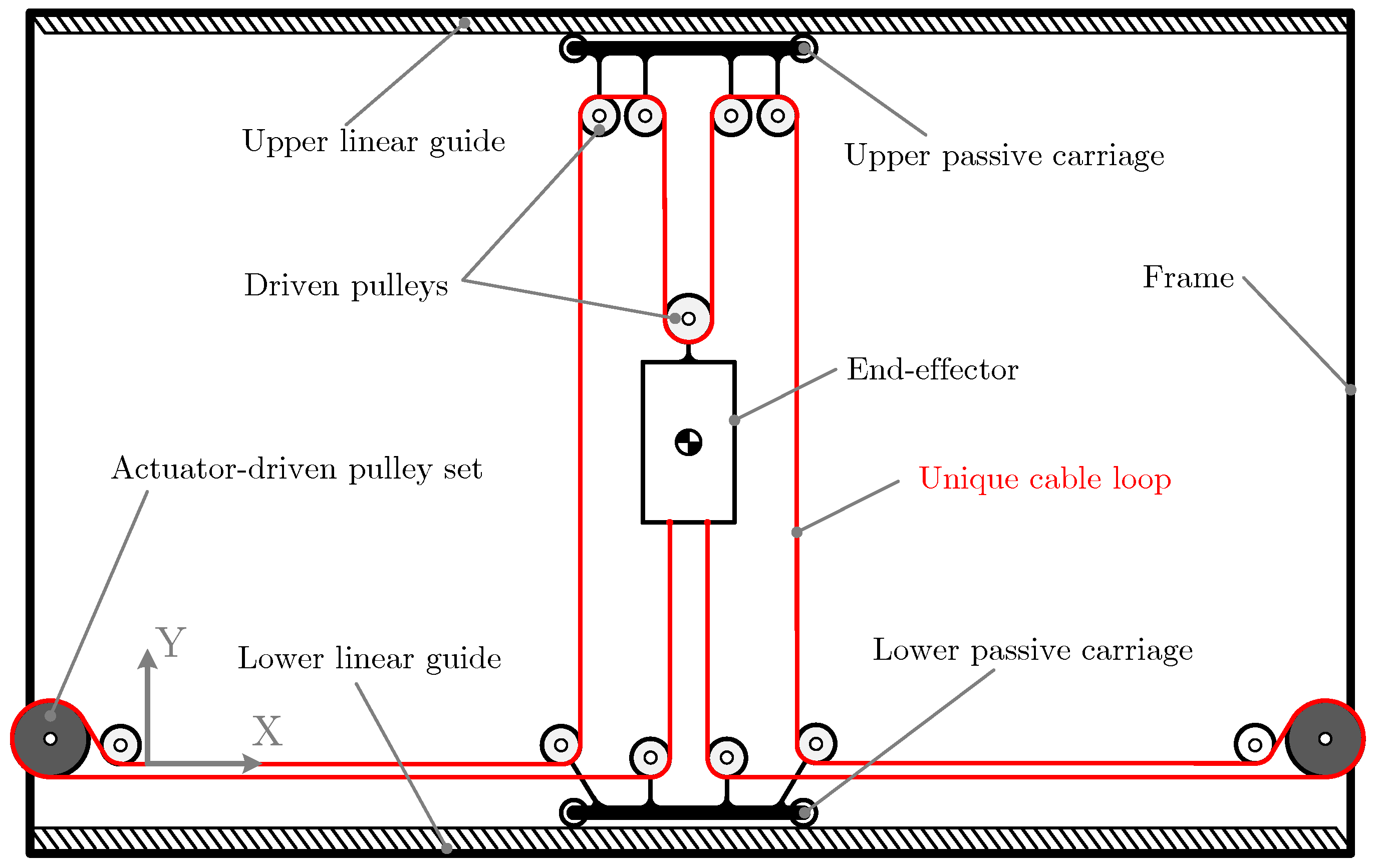
2.2. Novel single cable loop CDPR
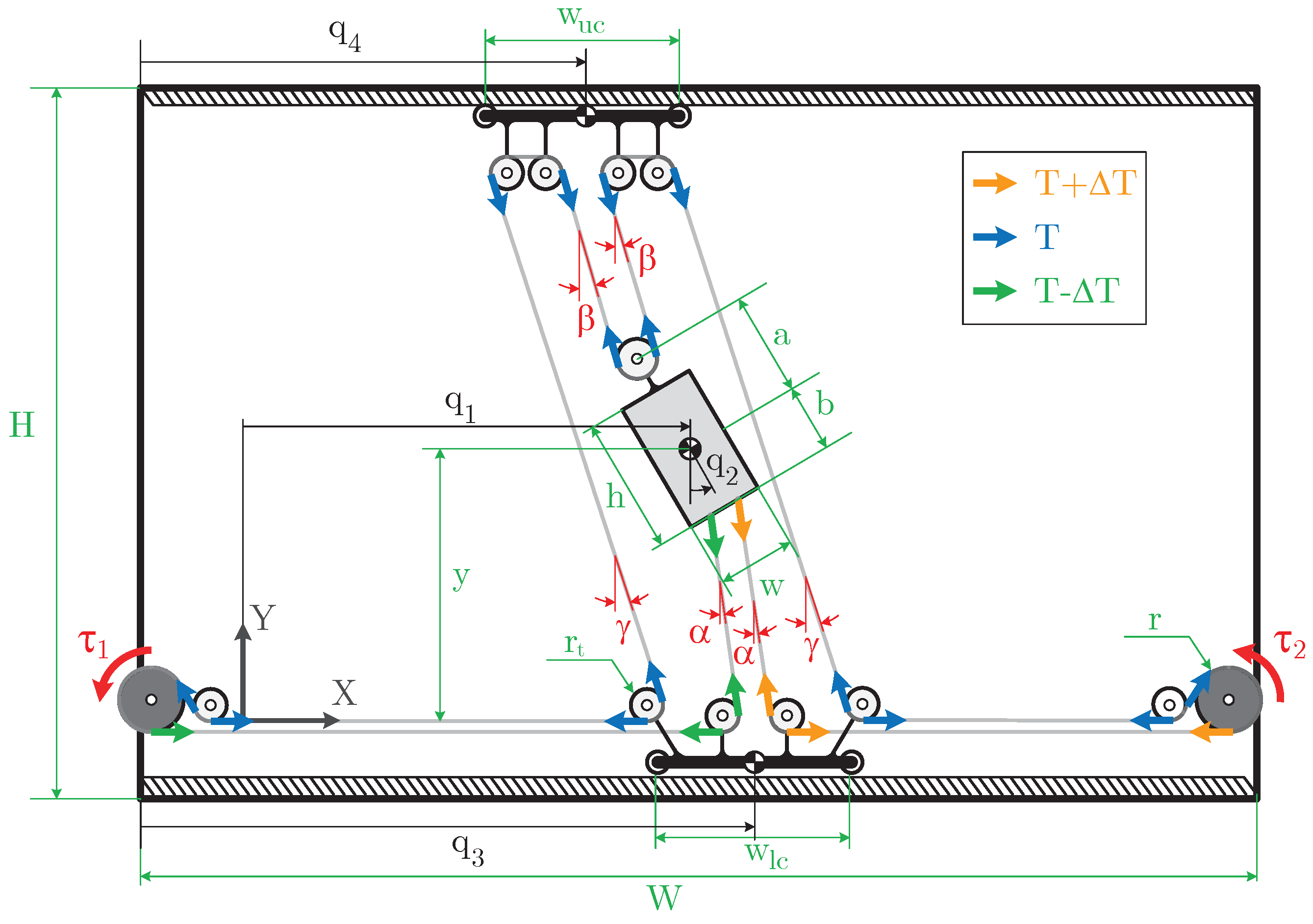
2.3. Nomenclature
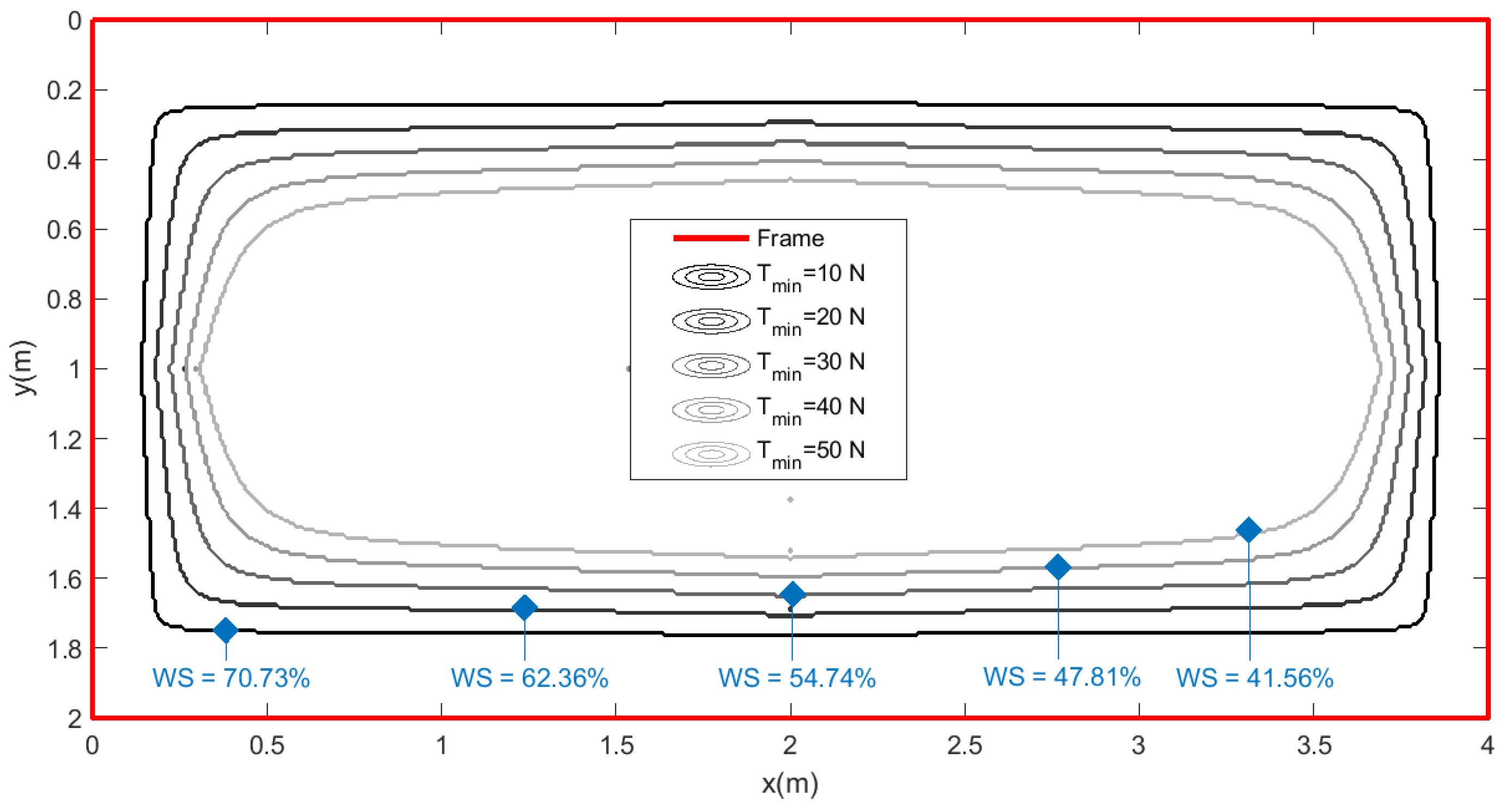
2.4. Workspace gain
3. Mathematical Model
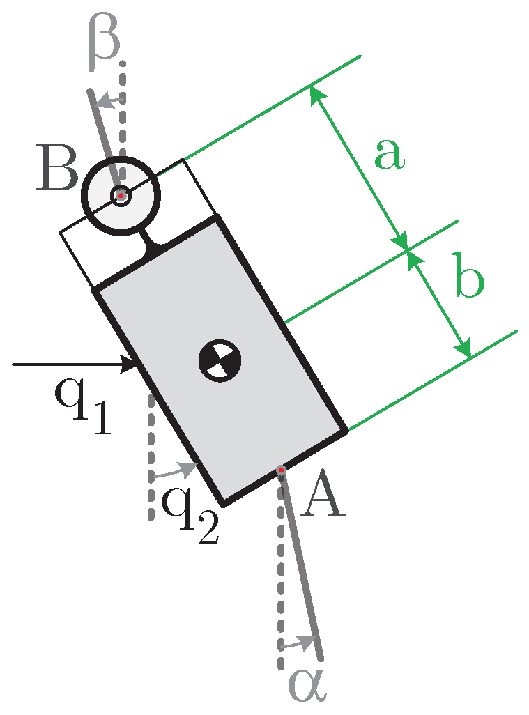
3.1. Kinematic Model
3.2. Dynamic Model
4. Experimental Platform Description
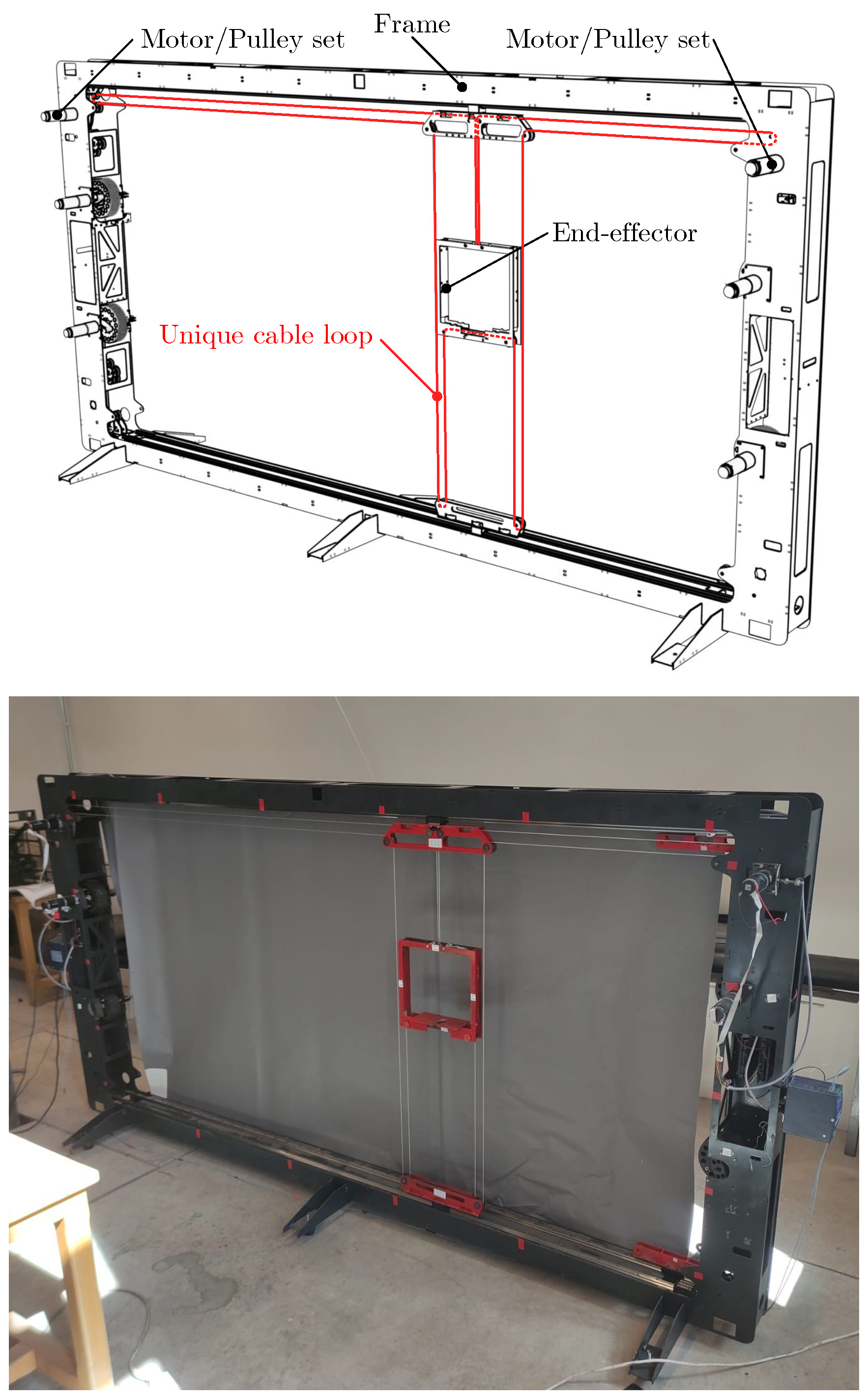
4.1. Robot description
| Frame | |
| Width, W (mm) | 2224 |
| Height, H (mm) | 1112 |
| End-effector | |
| Width, w (mm) | 287 |
| Height, h (mm) | 281 |
| Mass, (Kg) | 2.1 |
| Rotational Inertia, (Kg · m ) | |
| Cable | |
| Diameter, d (mm) | 2 |
| Young’s module, E (GPa) | 2.0912 |
| Passive Carriages | |
| Width, (mm) | 287 |
| Mass, (Kg) | 1.2 |
| Motor/Pulley sets | |
| Rotational Inertia, J (Kg · m ) | |
| Viscous friction coefficient, b (Nms) | 0.2 |
| Effective radius, r (mm) | 7.3 |
4.2. Computer vision system

5. Model identification and validation
5.1. Parameters identification
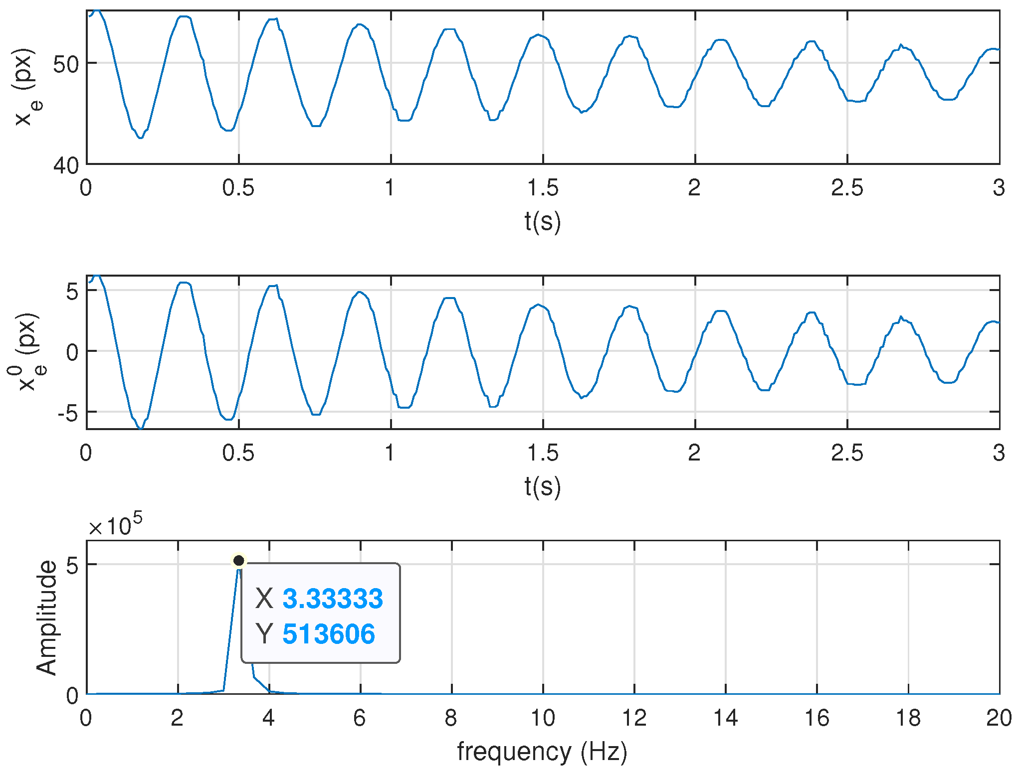
5.2. Frequency characterisation

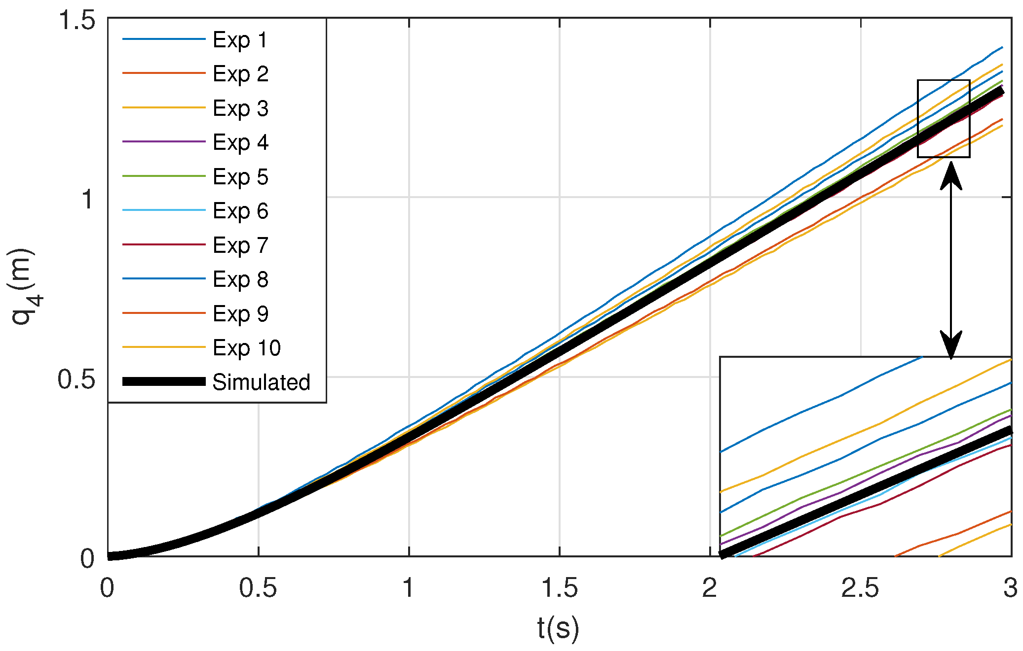
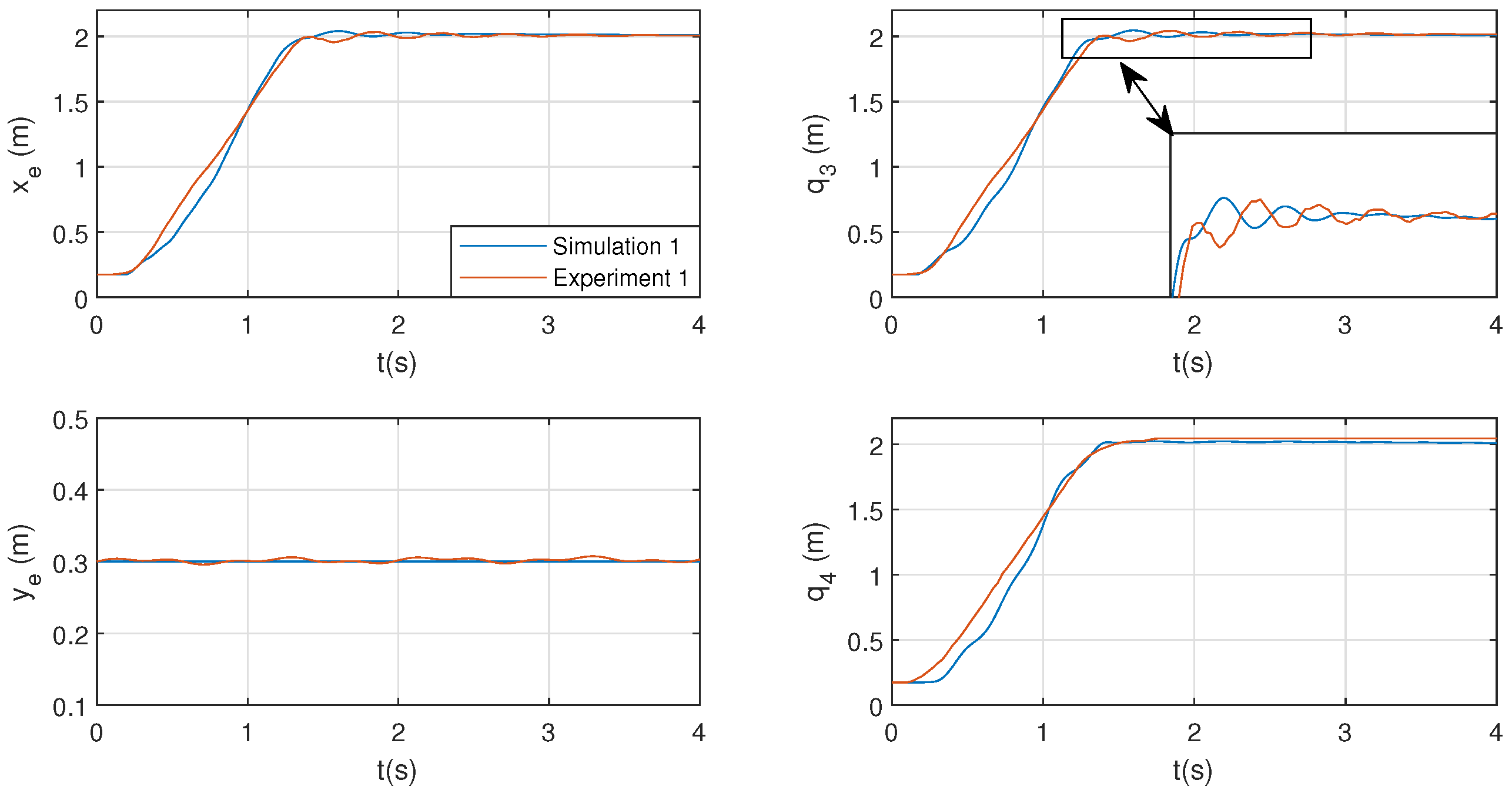
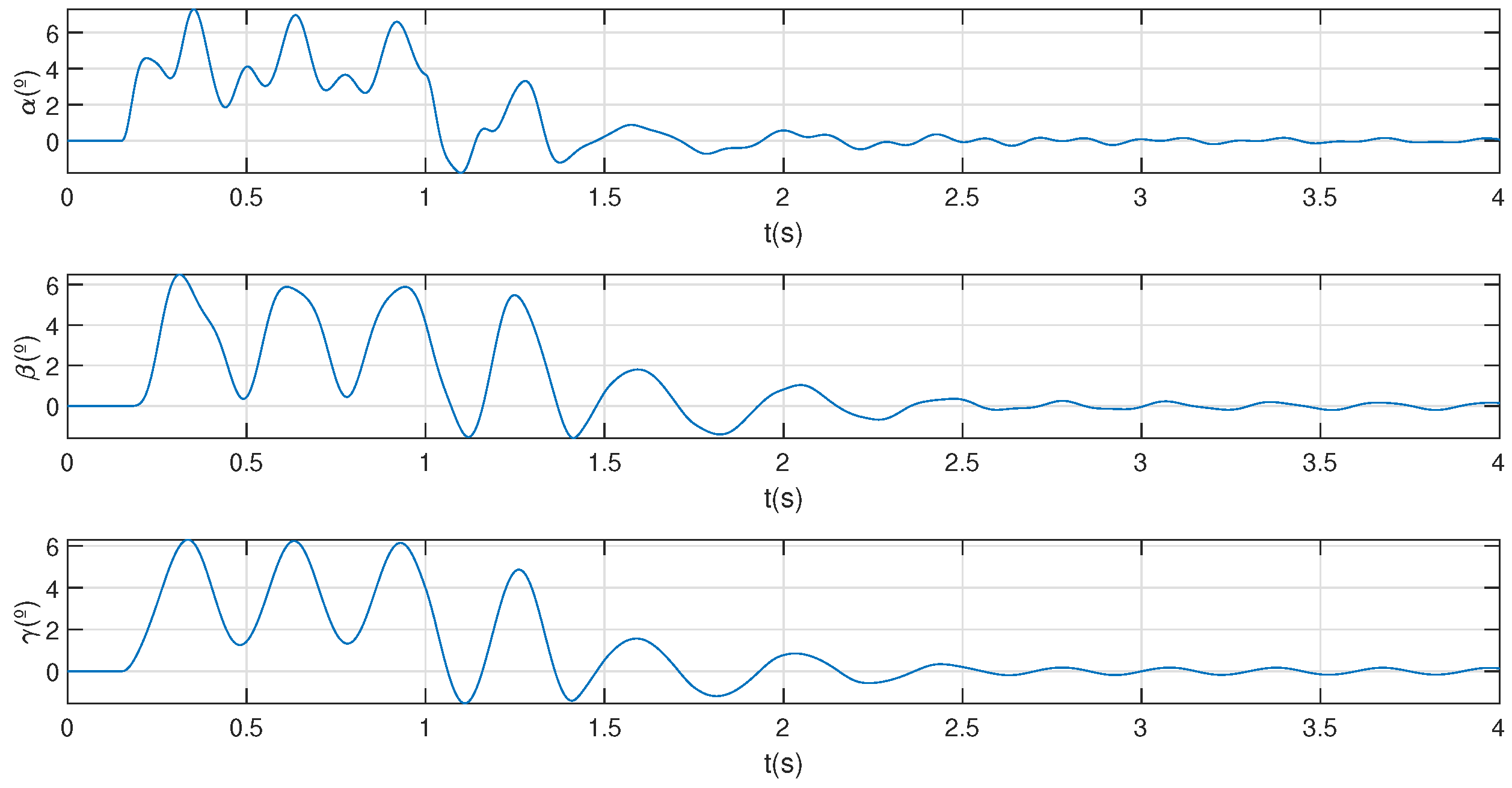
5.3. Model validation
| Experiment | End-effector position | Input torques |
| m | Nm | |
| 1 | ||
| 2 | ||
| 3 | ||
| 4 |
6. Kinematic control
6.1. Control scheme

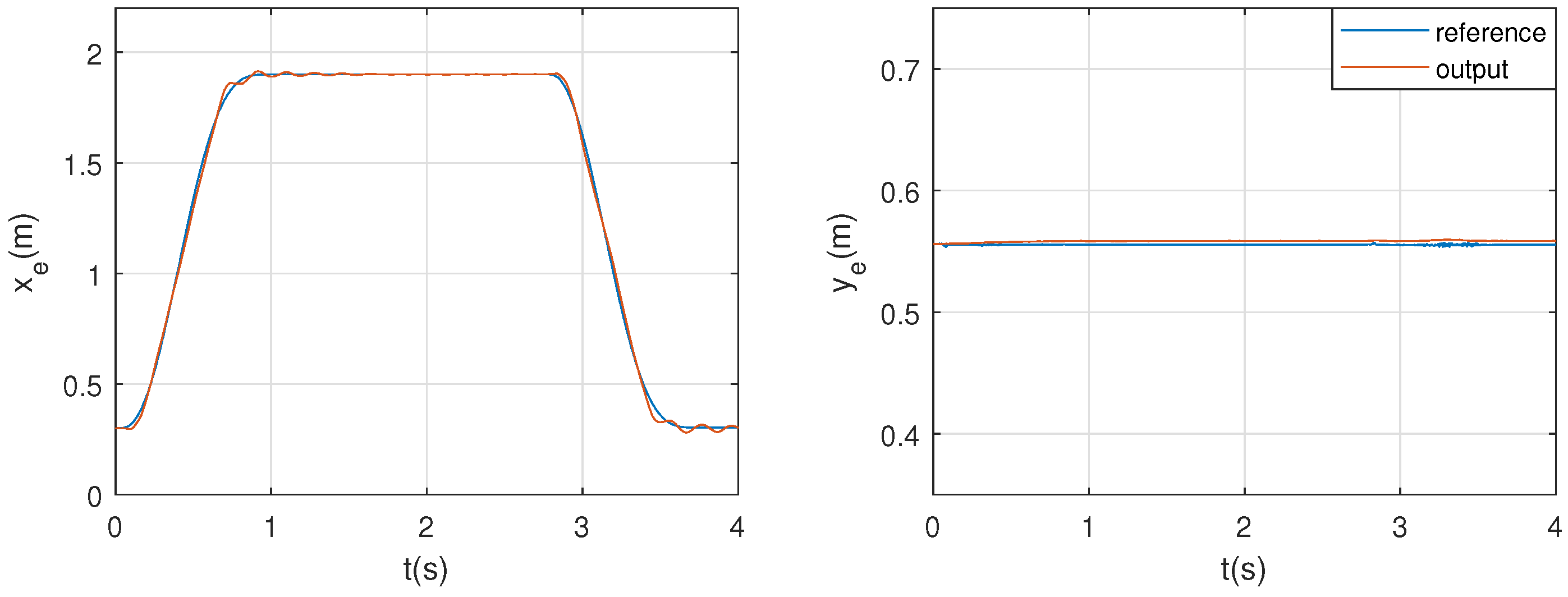
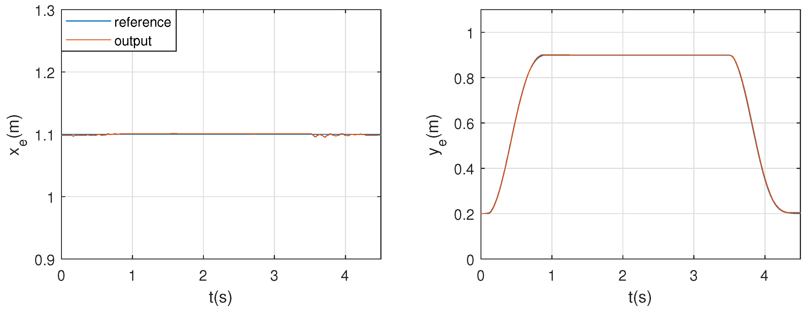
6.2. Position control results
| Trajectory | Initial pose | Intermediate pose | Final pose | Trajectory time |
| m | (s) | |||
| Horizontal | 4 | |||
| Vertical | 4.5 | |||

7. Conclusions
Author Contributions
Funding
Conflicts of Interest
Abbreviations
| CDPR | Cable-Driven Parallel Robot |
| sCDPR | Single Cable Cable-Driven Parallel Robot |
| DOF | Degree-of-freedom |
| WFW | Wrench-feasible workspace |
| FFT | Fast Fourier Transform |
| PD | Proportional-Derivative |
References
- Gouttefarde, M.; Bruckmann, T. Cable-driven parallel robots, 2022.
- Verhoeven, R. Analysis of the workspace of tendon based Stewart platforms. PhD thesis, Duisburg, Essen, Univ., Diss., 2004, 2006.
- Tho, T.P.; Thinh, N.T. An Overview of Cable-Driven Parallel Robots: Workspace, Tension Distribution, and Cable Sagging. Mathematical Problems in Engineering 2022, 2022. [Google Scholar] [CrossRef]
- Zi, B.; Duan, B.; Du, J.; Bao, H. Dynamic modeling and active control of a cable-suspended parallel robot. Mechatronics 2008, 18, 1–12. [Google Scholar] [CrossRef]
- Pott, A. Dynamics. In Cable-Driven Parallel Robots. Springer Tracts in Advanced Robotics; Springer International Publishing: Cham, 2018; pp. 229–254. [Google Scholar]
- Qian, S.; Zi, B.; Shang, W.W.; Xu, Q.S. A review on cable-driven parallel robots. Chinese Journal of Mechanical Engineering 2018, 31, 1–11. [Google Scholar] [CrossRef]
- Pott, A.; Pott, A. Geometric and Static Foundations. Cable-Driven Parallel Robots: Theory and Application 2018, pp. 45–117.
- Ming, A. Study on multiple degree-of-freedom positioning mechanism using wires (part 1). Int. J. Japan Soc. Precis. Eng. 1994, 28, 131–138. [Google Scholar]
- Lv, W.; Tao, L.; Ji, Z. Sliding mode control of cable-driven redundancy parallel robot with 6 DOF based on cable-length sensor feedback. Mathematical Problems in Engineering 2017, 2017. [Google Scholar] [CrossRef]
- Pott, A.; Pott, A. Workspace. Cable-Driven Parallel Robots: Theory and Application 2018, pp. 157–227.
- Gagliardini, L.; Caro, S.; Gouttefarde, M.; Girin, A. Discrete reconfiguration planning for cable-driven parallel robots. Mechanism and Machine Theory 2016, 100, 313–337. [Google Scholar] [CrossRef]
- Youssef, K.; Otis, M.J.D. Reconfigurable fully constrained cable driven parallel mechanism for avoiding interference between cables. Mechanism and Machine Theory 2020, 148, 103781. [Google Scholar] [CrossRef]
- An, H.; Yuan, H.; Tang, K.; Xu, W.; Wang, X. A Novel Cable-Driven Parallel Robot With Movable Anchor Points Capable for Obstacle Environments. IEEE/ASME Transactions on Mechatronics 2022, 27, 5472–5483. [Google Scholar] [CrossRef]
- Tan, H.; Nurahmi, L.; Pramujati, B.; Caro, S. On the reconfiguration of cable-driven parallel robots with multiple mobile cranes. 2020 5th International Conference on Robotics and Automation Engineering (ICRAE). IEEE, 2020, pp. 126–130.
- Barbazza, L.; Oscari, F.; Minto, S.; Rosati, G. Trajectory planning of a suspended cable driven parallel robot with reconfigurable end effector. Robotics and Computer-Integrated Manufacturing 2017, 48, 1–11. [Google Scholar] [CrossRef]
- Rodriguez-Barroso, A.; Saltaren, R.; Portilla, G.A.; Cely, J.S.; Carpio, M. Cable-driven parallel robot with reconfigurable end effector controlled with a compliant actuator. Sensors 2018, 18, 2765. [Google Scholar] [CrossRef] [PubMed]
- Castillo-Garcia, F.J.; Rubio-Gómez, G.; Juárez, S.; Rodríguez-Rosa, D.; Bravo, E.; Ottaviano, E.; Gonzalez-Rodriguez, A. Addition of passive-carriage for increasing workspace of cable robots: automated inspection of surfaces of civil infrastructures. Smart Structures and Systems, An International Journal 2021, 27, 387–396. [Google Scholar]
- Martin-Parra, A.; Juarez-Perez, S.; Gonzalez-Rodriguez, A.; Gonzalez-Rodriguez, A.G.; Lopez-Diaz, A.I.; Rubio-Gomez, G. A novel design for fully constrained planar Cable-Driven Parallel Robots to increase their wrench-feasible workspace. Mechanism and Machine Theory 2023, 180, 105159. [Google Scholar] [CrossRef]
- Ottaviano, E.; Arena, A.; Gattulli, V. Geometrically exact three-dimensional modeling of cable-driven parallel manipulators for end-effector positioning. Mechanism and Machine Theory 2021, 155, 104102. [Google Scholar] [CrossRef]
- Pott, A. Cable-Driven Parallel Robots; Vol. 1, Springer Science & Business Media, 2018.
- Yuan, H.; Courteille, E.; Deblaise, D. Static and dynamic stiffness analyses of cable-driven parallel robots with non-negligible cable mass and elasticity. Mechanism and Machine Theory 2015, 85, 64–81. [Google Scholar] [CrossRef]
- Abdolshah, S.; Zanotto, D.; Rosati, G.; Agrawal, S.K. Optimizing stiffness and dexterity of planar adaptive cable-driven parallel robots. Journal of Mechanisms and Robotics 2017, 9, 031004. [Google Scholar] [CrossRef]
- Tang, J.; Zhang, Y.; Huang, F.; Li, J.; Chen, Z.; Song, W.; Zhu, S.; Gu, J. Design and kinematic control of the cable-driven hyper-redundant manipulator for potential underwater applications. Applied Sciences 2019, 9, 1142. [Google Scholar] [CrossRef]
| 1 |
Disclaimer/Publisher’s Note: The statements, opinions and data contained in all publications are solely those of the individual author(s) and contributor(s) and not of MDPI and/or the editor(s). MDPI and/or the editor(s) disclaim responsibility for any injury to people or property resulting from any ideas, methods, instructions or products referred to in the content. |
© 2023 by the authors. Licensee MDPI, Basel, Switzerland. This article is an open access article distributed under the terms and conditions of the Creative Commons Attribution (CC BY) license (http://creativecommons.org/licenses/by/4.0/).


