Submitted:
13 April 2023
Posted:
14 April 2023
You are already at the latest version
Abstract
Keywords:
1. Introduction
- extremely low amount of fuel (as compared to fossil fuel power plants), which offers the possibility to store the fuel for many years of operation in advance, thus being independent from unstable political situations across the world,
- extremely low amount of waste (as compared to fossil fuel power plants),
- stable electrical energy generation (also heat generation if cogeneration is considered),
- extremely low usage of land (especially as compared to solar, wind and water power plants).
- zirconium alloys having hexagonal close packed (HCP) lattice. They are used for fuel cladding and thus are subjected to highest radiation. On the other hand, they have to survive only during the time between subsequent fuel replacements (typically around 6 years),
- austenitic stainless steels (ASS) having face centered cubic (FCC) lattice. They are used for reactor vessel internals, which fullfill many functions such as supporting the core, control rod assemblies, core support structure and reactor pressure vessel (RPV) surveilance capsules [3]. As they are inside the RPV, they are subjected to considerable neutron fluxes,
- ferritic steels of body centered cubic (BCC) lattice, such as e. g. US A508C1 or A533B, French 16MnD5, Russian 15Cr2MoVA and Chinese A508-3 steels, are used to build reactor pressure vessel. As the vessel is typically very large and has very thick walls, it is in principle the only part that cannot be replaced. Thus, its lifetime determines the service lifetime of the whole NPP.
- safety and reliability,
- sustainability,
- useful reactor life,
- proliferation-resistance,
- profitability.
- longer operation times,
- higher radiation doses,
- higher operating temperatures (especially in the case of VHTR),
- more chemically aggressive environments.
2. Irradiation-induced effects
3. Modelling irradiation effects
4. Nanoindentation
5. Conclusions
- Massive construction of new nuclear power plants is an essential requirement for meeting the CO reduction goals [1].
- Accounting for the effect of irradiation on mechanical properties in crystal plasticity theory started about 15 years ago and is still an area of active research.
- In particular, there is no consensus among different authors on whether various contributions to the CRSS should be superposed linearly or quadratically.
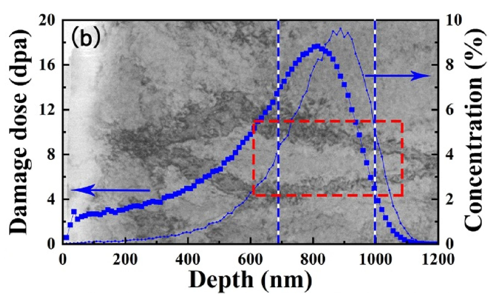
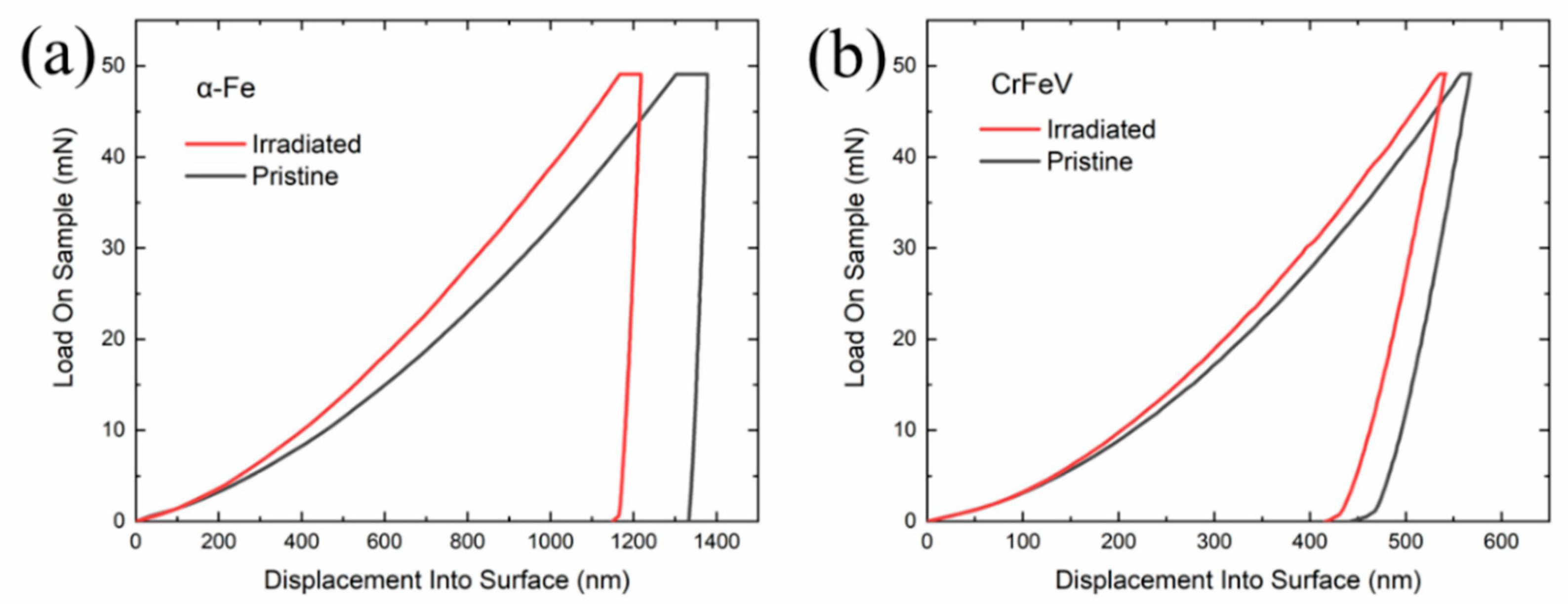
- Ion implantation is a cheap alternative to neutron irradiation but in order to measure the change in mechanical properties due to ion irradaition instrumented nanoindentation testing combined with CPFEM modelling is indispensable.
- One should account for ion penetration depth, size effects and indenter tip imperfection while performing CPFEM simulations of nanoindentation.
Funding
Data Availability Statement
Conflicts of Interest
Abbreviations
| NPP | nuclear power plant |
| PWR | pressurized water reactor |
| HCP | hexagonal close packed |
| ASS | austenitic stainless steels |
| FCC | face centered cubic |
| RPV | reactor pressure vessel |
| BCC | body centered cubic |
| DBTT | ductile to brittle transition temperature |
| Gen-IV | generation IV |
| GIF | Generation-IV International Forum |
| VHTR | very high temperature gas-cooled reactor |
| GFR | gas-cooled fast reactor |
| SFR | sodium-cooled fast reactor |
| LFR | lead-cooled fast reactor |
| MSR | molten salt reactor |
| SCWR | super-critical water-cooled reactor |
| FM | ferritic-martensitic |
| ODS | oxide dispersion strenghtened |
| PKA | primary knock-on atom |
| SFT | stacking fault tetrahedron |
| DL | dislocation loop |
| SRC | solute rich cluster |
| DBH | dispersed barrier hardening |
| dpa | displacement per atom |
| PCP | phenomenological crystal plasticity |
| DDCP | dislocation density based crystal plasticity |
| CRSS | critical resolved shear stress |
| RSS | resolved shear stress |
| IGSCC | intergranular stress corrosion cracking |
| CPFEM | crystal plasticity finite element method |
| FFT | fast Fourier transform |
| EVPSC | elastic-viscoplastic self-consistent |
| BZ | Berveiller and Zaoui |
| SC | self-consistent |
References
- Goldstein, J.; Qvist, S. A bright future: How some countries have solved climate change and the rest can follow; PublicAffairs, 2019.
- Fernández-Arias, P.; Vergara, D.; Orosa, J.A. A Global Review of PWR Nuclear Power Plants. Applied Sciences 2020, 10. [Google Scholar] [CrossRef]
- El Shawish, S.; Vincent, P.G.; Moulinec, H.; Cizelj, L.; Gélébart, L. Full-field polycrystal plasticity simulations of neutron-irradiated austenitic stainless steel: A comparison between FE and FFT-based approaches. J. Nucl. Mater. 2020, 529, 151927. [Google Scholar] [CrossRef]
- Chakraborty, P.; Biner, S.B. Crystal plasticity modeling of irradiation effects on flow stress in pure-iron and iron-copper alloys. Mechanics of Materials 2016, 101, 71–80. [Google Scholar] [CrossRef]
- Murty, K.L.; Charit, I. Structural materials for Gen-IV nuclear reactors: Challenges and opportunities. J. Nucl. Mater. 2008, 383, 189–195. [Google Scholar] [CrossRef]
- Abram, T.; Ion, S. Generation-IV nuclear power: A review of the state of the science. Energy Policy 2008, 36, 4323–4330. [Google Scholar] [CrossRef]
- Yvon, P.; Le Flem, M.; Cabet, C.; Seran, J.L. Structural materials for next generation nuclear systems: Challenges and the path forward. Nucl. Eng. Des. 2015, 294, 161–169. [Google Scholar] [CrossRef]
- Frelek-Kozak, M.; Kurpaska. ; Mulewska, K.; Zieliński, M.; Diduszko, R.; Kosińska, A.; Kalita, D.; Chromiński, W.; Turek, M.; Kaszyca, K.; et al. Mechanical behavior of ion-irradiated ODS RAF steels strengthened with different types of refractory oxides. Applied Surface Science 2023, 610, 155465. [Google Scholar] [CrossRef]
- Das, S.; Yu, H.; Mizohata, K.; Tarleton, E.; Hofmann, F. Modified deformation behaviour of self-ion irradiated tungsten: a combined nano-indentation, HR-EBSD and crystal plasticity study. International Journal of Plasticity 2020, 135, 102817. [Google Scholar] [CrossRef]
- El-Atwani, O.; Li, N.; Li, M.; Devaraj, A.; Baldwin, J.; Schneider, M.; Sobieraj, D.; Wróbel, J.; Nguyen-Manh, D.; Maloy, S.; et al. Outstanding radiation resistance of tungsten-based high-entropy alloys. Science advances 2019, 5, eaav2002. [Google Scholar] [CrossRef]
- Wang, Y.; Sun, X.; Zhao, J. A mechanism-based quantitative multi-scale framework for investigating irradiation hardening of tungsten at low temperature. Mater. Sci. Eng. A 2020, 774, 138941. [Google Scholar] [CrossRef]
- Garner, F.; Hamilton, M.; Panayotou, N.; Johnson, G. The microstructural origins of yield strength changes in AISI 316 during fission or fusion irradiation. Journal of Nuclear Materials 1981, 104, 803–807. [Google Scholar] [CrossRef]
- Odette, G.; Lucas, G. Recent progress in understanding reactor pressure vessel steel embrittlement. Radiation effects and defects in solids 1998, 144, 189–231. [Google Scholar] [CrossRef]
- Zinkle, S.; Maziasz, P.; Stoller, R. Dose dependence of the microstructural evolution in neutron-irradiated austenitic stainless steel. Journal of Nuclear materials 1993, 206, 266–286. [Google Scholar] [CrossRef]
- Zhang, H.; Long, B.; Dai, Y. Metallography studies and hardness measurements on ferritic/martensitic steels irradiated in STIP. Journal of Nuclear Materials 2008, 377, 122–131, Spalla- tion Materials Technology. [Google Scholar] [CrossRef]
- English, C.; Hyde, J. Radiation damage of reactor pressure vessel steels 2012.
- Slugeň, V.; Sojak, S.; Egger, W.; Krsjak, V.; Simeg Veternikova, J.; Petriska, M. Radiation damage of reactor pressure vessel steels studied by positron annihilation spectroscopy—A Review. Metals 2020, 10, 1378. [Google Scholar] [CrossRef]
- Monnet, G. Multiscale modeling of irradiation hardening: Application to important nuclear materials. J. Nucl. Mater. 2018, 508, 609–627. [Google Scholar] [CrossRef]
- Krishna, S.; Zamiri, A.; De, S. Dislocation and defect density-based micromechanical modeling of the mechanical behavior of FCC metals under neutron irradiation. Philos. Mag. 2010, 90, 4013–4025. [Google Scholar] [CrossRef]
- Patra, A.; McDowell, D. Crystal plasticity-based constitutive modelling of irradiated BCC structures. Philos. Mag. 2012, 92, 861–887. [Google Scholar] [CrossRef]
- Patra, A.; Tomé, C.; Golubov, S. Crystal plasticity modeling of irradiation growth in Zircaloy-2. Philos. Mag. 2017, 97, 2018–2051. [Google Scholar] [CrossRef]
- Xiao, X.; Terentyev, D.; Yu, L.; Bakaev, A.; Jin, Z.; Duan, H. Investigation of the thermo-mechanical behavior of neutron-irradiated Fe-Cr alloys by self-consistent plasticity theory. J. Nucl. Mater. 2016, 477, 123–133. [Google Scholar] [CrossRef]
- Chakraborty, P.; Biner, S.; Zhang, Y.; Spencer, B. Crystal plasticity model of reactor pressure vessel embrittlement in Grizzly. Technical report, Idaho National Lab.(INL), Idaho Falls, ID (United States), 2015.
- Seeger, A. On the theory of radiation damage and radiation hardening. In Proceedings of the Proceedings of the 2nd UN International Conference on Peaceful Uses of Atomic Energy, 1958, Vol. 6, p. 250.
- Roldán, M.; Sánchez, F.J.; Fernández, P.; Ortiz, C.J.; Gómez-Herrero, A.; Rey, D.J. Dislocation Loop Generation Differences between Thin Films and Bulk in EFDA Pure Iron under Self-Ion Irradiation at 20 MeV. Metals 2021, 11. [Google Scholar] [CrossRef]
- Patra, A.; McDowell, D. A void nucleation and growth based damage framework to model failure initiation ahead of a sharp notch in irradiated BCC materials. J. Mech. Phys. Solids 2015, 74, 111–135. [Google Scholar] [CrossRef]
- Weeks, J.; Czajkowski, C.; Tichler, P. Effects of high thermal and high fast fluences on the mechanical properties of type 6061 aluminum on the HFBR. In Proceedings of the Effects of Radiation on Materials: 14th International Symposium (Volume II). ASTM International; 1990. [Google Scholar]
- Griffiths, M. Effect of Neutron Irradiation on the Mechanical Properties, Swelling and Creep of Austenitic Stainless Steels. Materials 2021, 14. [Google Scholar] [CrossRef] [PubMed]
- Bergner, F.; Hernández-Mayoral, M.; Heintze, C.; Konstantinović, M.J.; Malerba, L.; Pareige, C. TEM Observation of Loops Decorating Dislocations and Resulting Source Hardening of Neutron-Irradiated Fe-Cr Alloys. Metals 2020, 10. [Google Scholar] [CrossRef]
- Zhang, F.; Boatner, L.; Zhang, Y.; Chen, D.; Wang, Y.; Wang, L. Swelling and Helium Bubble Morphology in a Cryogenically Treated FeCrNi Alloy with Martensitic Transformation and Reversion after Helium Implantation. Materials 2019, 12. [Google Scholar] [CrossRef]
- Kinchin, G.H.; Pease, R.S. The displacement of atoms in solids by radiation. Reports on progress in physics 1955, 18, 1. [Google Scholar] [CrossRef]
- Was, G.S. Fundamentals of radiation materials science: metals and alloys; Springer, 2017.
- Ziegler, J.F.; Ziegler, M.; Biersack, J. SRIM – The stopping and range of ions in matter (2010). Nuclear Instruments and Methods in Physics Research Section B: Beam Interactions with Materials and Atoms 2010, 268, 1818–1823, 19th International Conference on Ion Beam Analysis. [Google Scholar] [CrossRef]
- Crocombette, Jean-Paul. ; Van Wambeke, Christian. Quick calculation of damage for ion irradiation: implementation in Iradina and comparisons to SRIM. EPJ Nuclear Sci. Technol. 2019, 5, 7. [Google Scholar] [CrossRef]
- Perzyna, P. Theory of viscoplasticity of irradiated materials. Archives of Mechanics 1974, 26, 81–93. [Google Scholar]
- Arsenlis, A.; Wirth, B.; Rhee, M. Dislocation density-based constitutive model for the mechanical behaviour of irradiated Cu. Philos. Mag. 2004, 84, 3617–3635. [Google Scholar] [CrossRef]
- Skoczeń, B.; Ustrzycka, A. Kinetics of evolution of radiation induced micro-damage in ductile materials subjected to time-dependent stresses. Int. J. Plast. 2016, 80, 86–110. [Google Scholar] [CrossRef]
- Ryś, M.; Skoczeń, B. Coupled constitutive model of damage affected two-phase continuum. Mech. Mater. 2017, 115, 1–15. [Google Scholar] [CrossRef]
- Ustrzycka, A.; Skoczeń, B.; Nowak, M.; Kurpaska, .; Wyszkowska, E.; Jagielski, J. Elastic–plastic-damage model of nano-indentation of the ion-irradiated 6061 aluminium alloy. Int. J. Damage Mech. 2020, p. 1056789520906209.
- Nowak, M.; Mulewska, K.; Azarov, A.; Ustrzycka, A.; et al. A peridynamic elasto-plastic damage model for ion-irradiated materials. International Journal of Mechanical Sciences 2023, 237, 107806. [Google Scholar] [CrossRef]
- Deo, C.; Tomé, C.; Lebensohn, R.; Maloy, S. Modeling and simulation of irradiation hardening in structural ferritic steels for advanced nuclear reactors. J. Nucl. Mater. 2008, 377, 136–140. [Google Scholar] [CrossRef]
- Onimus, F.; Béchade, J.L. A polycrystalline modeling of the mechanical behavior of neutron irradiated zirconium alloys. J. Nucl. Mater. 2009, 384, 163–174. [Google Scholar] [CrossRef]
- Erinosho, T.; Dunne, F. Strain localization and failure in irradiated zircaloy with crystal plasticity. Int. J. Plast. 2015, 71, 170–194. [Google Scholar] [CrossRef]
- Onimus, F.; Gelebart, L.; Brenner, R. Polycrystalline simulations of in-reactor deformation of recrystallized Zircaloy-4 tubes: Fast Fourier Transform computations and mean-field self-consistent model. International Journal of Plasticity 2022, 153, 103272. [Google Scholar] [CrossRef]
- Vincent, L.; Libert, M.; Marini, B.; Rey, C. Towards a modelling of RPV steel brittle fracture using crystal plasticity computations on polycrystalline aggregates. J. Nucl. Mater. 2010, 406, 91–96. [Google Scholar] [CrossRef]
- Asaro, R.J.; Needleman, A. Texture Development and Strain Hardening in Rate Dependent Polycrystals. Acta Metall. 1985, 33, 923–953. [Google Scholar] [CrossRef]
- Frydrych, K.; Kowalczyk-Gajewska, K. A three-scale crystal plasticity model accounting for grain refinement in FCC metals subjected to severe plastic deformations. Mater. Sci. Eng. A 2016, 658, 490–502. [Google Scholar] [CrossRef]
- Frydrych, K. Simulations of Grain Refinement in Various Steels Using the Three-Scale Crystal Plasticity Model. Metall. Mater. Trans. A 2019, 50, 4913–4919. [Google Scholar] [CrossRef]
- Girard, G.; Frydrych, K.; Kowalczyk-Gajewska, K.; Martiny, M.; Mercier, S. Cyclic response of electrodeposited copper films. Experiments versus elastic-viscoplastic mean-field approach predictions. Mech. Mater. 2021, 153, 1–17. [Google Scholar] [CrossRef]
- Frydrych, K.; Dominguez, J.; Alava, M.; Papanikolaou, S. Multiscale nanoindentation modeling of concentrated solid solutions: A continuum plasticity model. Mechanics of Materials 2023, 181, 104644. [Google Scholar] [CrossRef]
- Kothari, M.; Anand, L. Elasto-viscoplastic constitutive equations for polycrystalline metals: Application to tantalum. J. Mech. Phys. Solids 1998, 46, 51–83. [Google Scholar] [CrossRef]
- Kocks, U.F.; Argon, A.S.; Ashby, M.F. Thermodynamics and kinetics of slip. Progress in Materials Science 1975, 19. [Google Scholar]
- Orowan, E. Problems of plastic gliding. Proc. Phys. Soc. 1940, 52, 8. [Google Scholar] [CrossRef]
- Krishna, S.; De, S. A temperature and rate-dependent micromechanical model of molybdenum under neutron irradiation. Mech. Mater. 2011, 43, 99–110. [Google Scholar] [CrossRef]
- Han, X. Modeling of cavity swelling-induced embrittlement in irradiated austenitic stainless steels; Modelisation de la fragilisation due au gonflement dans les aciers inoxydables austenitiques irradies. PhD thesis, Ecole Nationale Superieure des Mines de Paris Univ., Paris, France, 2012.
- Tanguy, B.; Han, X.; Besson, J.; Forest, S.; Robertson, C.; Rupin, N. Dislocations and irradiation defects-based micromechanical modelling for neutron irradiated austenitic stainless steels. In Proceedings of the International Symposium on Plasticity; 2013; pp. 3–8. [Google Scholar]
- El Shawish, S.; Cizelj, L.; Tanguy, B.; Han, X.; Hure, J. Extended crystal plasticity finite element approach for neutron irradiated austenitic stainless steels. In Proceedings of the 23rd Int. Conf. Nuclear Energy for New Europe; 2014. [Google Scholar]
- El Shawish, S.; Cizelj, L.; Tanguy, B.; Han, X.; Hure, J. Macroscopic Validation of the Micromechanical Model for Neutron-Irradiated Stainless Steel. In Proceedings of the 25th Int. Conf. Nuclear Energy for New Europe; 2016. [Google Scholar]
- Hure, J.; El Shawish, S.; Cizelj, L.; Tanguy, B. Intergranular stress distributions in polycrystalline aggregates of irradiated stainless steel. J. Nucl. Mater. 2016, 476, 231–242. [Google Scholar] [CrossRef]
- Ling, C.; Tanguy, B.; Besson, J.; Forest, S.; Latourte, F. Void growth and coalescence in triaxial stress fields in irradiated FCC single crystals. J. Nucl. Mater. 2017, 492, 157–170. [Google Scholar] [CrossRef]
- Vincent, P.G.; Moulinec, H.; Joëssel, L.; Idiart, M.I.; Gărăjeu, M. Porous polycrystal plasticity modeling of neutron-irradiated austenitic stainless steels. J. Nucl. Mater. 2020, p. 15246.
- Patra, A.; McDowell, D. Continuum modeling of localized deformation in irradiated BCC materials. J. Nucl. Mater. 2013, 432, 414–427. [Google Scholar] [CrossRef]
- Barton, N.; Arsenlis, A.; Marian, J. A polycrystal plasticity model of strain localization in irradiated iron. J. Mech. Phys. Solids 2013, 61, 341–351. [Google Scholar] [CrossRef]
- Xiao, X.; Song, D.; Xue, J.; Chu, H.; Duan, H. A size-dependent tensorial plasticity model for FCC single crystal with irradiation. Int. J. Plast. 2015, 65, 152–167. [Google Scholar] [CrossRef]
- Xiao, X.; Song, D.; Xue, J.; Chu, H.; Duan, H. A self-consistent plasticity theory for modeling the thermo-mechanical properties of irradiated FCC metallic polycrystals. J. Mech. Phys. Solids 2015, 78, 1–16. [Google Scholar] [CrossRef]
- Sabar, H.; Berveiller, M.; Favier, V.; Berbenni, S. A new class of micro-micro models for elastic-viscoplastic heterogeneous materials. Int. J. Solids Struct. 2002, 39, 3257–3276. [Google Scholar] [CrossRef]
- Xiao, X.; Terentyev, D.; Yu, L.; Song, D.; Bakaev, A.; Duan, H. Modelling irradiation-induced softening in BCC iron by crystal plasticity approach. J. Nucl. Mater. 2015, 466, 312–315. [Google Scholar] [CrossRef]
- Song, D.; Xiao, X.; Xue, J.; Chu, H.; Duan, H. Mechanical properties of irradiated multi-phase polycrystalline BCC materials. Acta Mechanica Sinica 2015, 31, 191–204. [Google Scholar] [CrossRef]
- Nie, J.; Liu, Y.; Xie, Q.; Liu, Z. Study on the irradiation effect of mechanical properties of RPV steels using crystal plasticity model. Nucl. Eng. Technol. 2019, 51, 501–509. [Google Scholar] [CrossRef]
- Nie, J.; Liu, Y.; Lin, P.; Xie, Q.; Liu, Z. A crystal plasticity model with irradiation effect for the mechanical behavior of FCC metals. Acta Mechanica Solida Sinica 2019, 32, 675–687. [Google Scholar] [CrossRef]
- Monnet, G.; Mai, C. Prediction of irradiation hardening in austenitic stainless steels: Analytical and crystal plasticity studies. J. Nucl. Mater. 2019, 518, 316–325. [Google Scholar] [CrossRef]
- Berveiller, M.; Zaoui, A. An extension of the self-consistent scheme to the plastically flowing polycrystals. J. Mech. Phys. Solids 1978, 26, 325–344. [Google Scholar] [CrossRef]
- Monnet, G.; Vincent, L.; Gélébart, L. Multiscale modeling of crystal plasticity in Reactor Pressure Vessel steels: Prediction of irradiation hardening. J. Nucl. Mater. 2019, 514, 128–138. [Google Scholar] [CrossRef]
- Patra, A.; McDowell, D. Crystal plasticity investigation of the microstructural factors influencing dislocation channeling in a model irradiated BCC material. Acta Mater. 2016, 110, 364–376. [Google Scholar] [CrossRef]
- Singh, K.; Robertson, C.; Bhaduri, A. Brittle fracture model parameter estimation for irradiated BCC material through dislocation based crystal plasticity model. Frat. ed Integrità Strutt. 2019, 13, 319–330. [Google Scholar] [CrossRef]
- Lebensohn, R.A.; Tomé, C.N. A self-consistent anisotropic approach for the simulation of plastic deformation and texture development of polycrystals: Application to zirconium alloys. Acta Metall. Mater. 1993, 41, 2611–2624. [Google Scholar] [CrossRef]
- Hosemann, P.; Vieh, C.; Greco, R.; Kabra, S.; Valdez, J.; Cappiello, M.; Maloy, S. Nanoindentation on ion irradiated steels. J. Nucl. Mater. 2009, 389, 239–247. [Google Scholar] [CrossRef]
- Hosemann, P.; Kiener, D.; Wang, Y.; Maloy, S.A. Issues to consider using nano indentation on shallow ion beam irradiated materials. J. Nucl. Mater. 2012, 425, 136–139. [Google Scholar] [CrossRef]
- Kucharski, S.; Jarząbek, D. Depth dependence of nanoindentation pile-up patterns in copper single crystals. Metall. Mater. Trans. A 2014, 45, 4997–5008. [Google Scholar] [CrossRef]
- Zaborowska, A.; Kurpaska. ; Wyszkowska, E.; Clozel, M.; Vanazzi, M.; Di Fonzo, F.; Turek, M.; Jóźwik, I.; Kosińska, A.; Jagielski, J. Influence of ion irradiation on the nanomechanical properties of thin alumina coatings deposited on 316L SS by PLD. Surface and Coatings Technology 2020, 386, 125491. [Google Scholar] [CrossRef]
- Clozel, M.; Kurpaska, L.; Jóźwik, I.; Jagielski, J.; Turek, M.; Diduszko, R.; Wyszkowska, E. Nanomechanical properties of low-energy Fe-ion implanted Eurofer97 and pure Fe. Surface and Coatings Technology 2020, 393, 125833. [Google Scholar] [CrossRef]
- Mulewska, K.; Rovaris, F.; Dominguez-Gutierrez, F.; Huo, W.; Kalita, D.; Jozwik, I.; Papanikolaou, S.; Alava, M.; Kurpaska, L.; Jagielski, J. Self-ion irradiation effects on nanoindentation-induced plasticity of crystalline iron: A joint experimental and computational study. Nuclear Instruments and Methods in Physics Research Section B: Beam Interactions with Materials and Atoms 2023, 539, 55–61. [Google Scholar] [CrossRef]
- Huang, W.; Sun, M.; Wen, W.; Yang, J.; Xie, Z.; Liu, R.; Wang, X.; Wu, X.; Fang, Q.; Liu, C. Strain Profile in the Subsurface of He-Ion-Irradiated Tungsten Accessed by S-GIXRD. Crystals 2022, 12. [Google Scholar] [CrossRef]
- Su, Y.; Xia, S.; Huang, J.; Liu, Q.; Liu, H.; Wang, C.; Wang, Y. Irradiation Behaviors in BCC Multi-Component Alloys with Different Lattice Distortions. Metals 2021, 11. [Google Scholar] [CrossRef]
- Kucharski, S.; Stupkiewicz, S.; Petryk, H. Surface Pile-Up Patterns in Indentation Testing of Cu Single Crystals. Exper. Mech. 2014, 54, 957–969. [Google Scholar] [CrossRef]
- Petryk, H.; Stupkiewicz, S.; Kucharski, S. On direct estimation of hardening exponent in crystal plasticity from the spherical indentation test. Int. J. Solids Struct. 2017, 112, 209–221. [Google Scholar] [CrossRef]
- Chakraborty, A.; Eisenlohr, P. Evaluation of an inverse methodology for estimating constitutive parameters in face-centered cubic materials from single crystal indentations. European Journal of Mechanics - A/Solids 2017, 66, 114–124. [Google Scholar] [CrossRef]
- Frydrych, K. Crystal plasticity finite element simulations of the indentation test. Comput. Methods Mater. Sci. 2019, 19, 41–49. [Google Scholar] [CrossRef]
- Ryś, M.; Stupkiewicz, S.; Petryk, H. Micropolar regularization of crystal plasticity with the gradient-enhanced incremental hardening law. Int. J. Plast. 2022. [Google Scholar] [CrossRef]
- Frydrych, K.; Papanikolaou, S. Unambiguous Identification of Crystal Plasticity Parameters from Spherical Indentation. Crystals 2022, 12, 1341. [Google Scholar] [CrossRef]
- Wang, Q.; Cochrane, C.; Skippon, T.; Wang, Z.; Abdolvand, H.; Daymond, M.R. Orientation-dependent irradiation hardening in pure Zr studied by nanoindentation, electron microscopies, and crystal plasticity finite element modeling. Int. J. Plast. 2019, 124, 133–154. [Google Scholar] [CrossRef]
- Xiao, X.; Chen, L.; Yu, L.; Duan, H. Modelling nano-indentation of ion-irradiated FCC single crystals by strain-gradient crystal plasticity theory. Int. J. Plast. 2019, 116, 216–231. [Google Scholar] [CrossRef]
- Nie, J.; Lin, P.; Liu, Y.; Zhang, H.; Wang, X. Simulation of the irradiation effect on hardness of Chinese HTGR A508-3 steels with CPFEM. Nucl. Eng. Technol. 2019, 51, 1970–1977. [Google Scholar] [CrossRef]
- Shi, J.; Liu, G.; Wu, K.; Yu, P.; Zhu, H.; Zhao, G.; Shen, Y. Experiments and/or crystal plasticity finite element modeling of the mechanical properties of pristine and irradiated tungsten single crystal. International Journal of Plasticity 2022, 154, 103293. [Google Scholar] [CrossRef]
- Xiao, X.; Li, S.; Yu, L. Effect of irradiation damage and indenter radius on pop-in and indentation stress-strain relations: Crystal plasticity finite element simulation. Int. J. Mech. Sci. 2021, 199, 106430. [Google Scholar] [CrossRef]
- Petryk, H.; Stupkiewicz, S. A minimal gradient-enhancement of the classical continuum theory of crystal plasticity. Part I: The hardening law. Arch. Mech. 2016, 68, 459–485. [Google Scholar]
- Stupkiewicz, S.; Petryk, H. A minimal gradient-enhancement of the classical continuum theory of crystal plasticity. Part II: Size effects. Arch. Mech. 2016, 68, 487–513. [Google Scholar]
- Lewandowski, M.; Stupkiewicz, S. Size effects in wedge indentation predicted by a gradient-enhanced crystal-plasticity model. Int. J. Plast. 2018. [Google Scholar] [CrossRef]
- Torres-Torres, D.; Muñoz-Saldaña, J.; Gutierrez-Ladron-de Guevara, L.; Hurtado-Macías, A.; Swain, M. Geometry and bluntness tip effects on elastic–plastic behaviour during nanoindentation of fused silica: experimental and FE simulation. Model. Simul. Mater. Sci. Eng. 2010, 18, 075006. [Google Scholar] [CrossRef]
- Krier, J.; Breuils, J.; Jacomine, L.; Pelletier, H. Introduction of the real tip defect of Berkovich indenter to reproduce with FEM nanoindentation test at shallow penetration depth. J. Mater. Res. 2012, 27, 28–38. [Google Scholar] [CrossRef]
- Čech, J.; Haušild, P.; Kovářík, O.; Materna, A. Examination of Berkovich indenter tip bluntness. Materials & Design 2016, 109, 347–353. [Google Scholar]
- Kovář, J.; Fuis, V.; Tomáštík, J. Influencing the indentation curves by the bluntness of the Berkovich indenter at the FEM modelling 2020.
- Sanchez-Camargo, C.M.; Hor, A.; Mabru, C. A robust inverse analysis method for elastoplastic behavior identification using the true geometry modeling of Berkovich indenter. Int. J. Mech. Sci. 2020, 171, 105370. [Google Scholar] [CrossRef]
- Frydrych, K. The influence of the Berkovich tip defect on the results of the nanoindentation simulations. In preparation 2023. [Google Scholar]
| 1 | The pressurized water reactors (PWRs, cf. [2]) are considered here, as they are the most commonly operated NPPs. |

Disclaimer/Publisher’s Note: The statements, opinions and data contained in all publications are solely those of the individual author(s) and contributor(s) and not of MDPI and/or the editor(s). MDPI and/or the editor(s) disclaim responsibility for any injury to people or property resulting from any ideas, methods, instructions or products referred to in the content. |
© 2023 by the authors. Licensee MDPI, Basel, Switzerland. This article is an open access article distributed under the terms and conditions of the Creative Commons Attribution (CC BY) license (http://creativecommons.org/licenses/by/4.0/).


