Preprint
Article

Effect of Injection Strategy on the Flow Structure and Performance of Water Ramjet Engine using Magnesium Powder

Altmetrics

Downloads

136

Views

50

Comments

0

Submitted:

14 April 2023

Posted:

17 April 2023

You are already at the latest version

Alerts
Abstract
Different inlet structures have a significant impact on the internal flow characteristics of a solid-magnesium powder water ramjet engine. Based on the magnesium-water reaction model, a computational fluid dynamics (CFD) method is applied to establish a numerical simulation method for the internal flow field of the engine, and the internal flow characteristics of the engine under different inlet structure conditions are studied. The simulation results show that high-temperature gas can effectively promote the ignition of magnesium powder at the top of the combustion chamber, while accelerating the evaporation of the first inlet water and increasing the combustion rate of magnesium powder. The secondary inlet has the most significant effect on the temperature inside the combustion chamber. When the secondary inlet flow rate increases towards the top of the combustion chamber, it increases the amount of heat absorbed by the evaporating water at the top of the chamber, thereby reducing the temperature at the top of the combustion chamber. However, when the flow rate is low, it results in insufficient oxidizer at the top of the combustion chamber, which is unfavorable for the combustion of magnesium powder.
Keywords: 
Subject: Engineering  -   Aerospace Engineering

1. Introduction

Metal/water reaction ramjet engine is a new type of underwater propulsion device that uses high-energy reactive metals (aluminum, magnesium) as fuel and external seawater as oxidant and main working fluid. Due to the high volumetric heating value of metal fuel and the fact that ramjet engines do not require oxidants to be carried, they have a high energy density and specific impulse [1,2,3]. In addition, ramjet engines have the advantages of simple structure and high reliability, making them an ideal ultra-high-speed underwater weapon propulsion device that can meet the requirements of high speed and long range [4,5,6].
In recent years, scholars at home and abroad have conducted a large amount of research on ramjet engines, from basic principle demonstration to specific performance parameter analysis and comparison, laying the foundation for further tackling the technical difficulties of ramjet engine technology. Among the many ramjet engine schemes, powder water ramjet, with its excellent energy density and flexible energy management characteristics, is an important development trend for future ramjet engines.
In the working process of the powder-based water ramjet engine, the metal fuel enters the engine in the form of particles with low initial temperature, which makes efficient combustion difficult [7,8]. Referring to the design method of boron-based powder fuel ramjet engine, a solid-powder water ramjet engine is introduced, which uses high-temperature combustion gas to quickly preheat and raise the temperature of the powder[9], shorten the ignition time of the metal fuel, and use high-temperature combustion gas to promote water droplet evaporation and enhance the reaction between metal and water inside the engine [10]. In the working process of the engine, the powder fuel is first mixed and heated with the combustion gas, and then the molten metal fuel is mixed and burned with atomized water [11,12,13]. This process involves multiple complex physical processes, such as preheating and heating of powder fuel, evaporation of water droplets, and mixing and combustion of molten metal and water vapor, which are coupled and have a significant impact on the internal flow field of the engine [14,15]. In this paper, numerical simulation is used to describe the internal flow field of the solid-magnesium powder water ramjet engine and explore the influence of inlet forms on the internal flow field of the engine.

2. Physical Model and Calculation Method

2.1. Physical Model

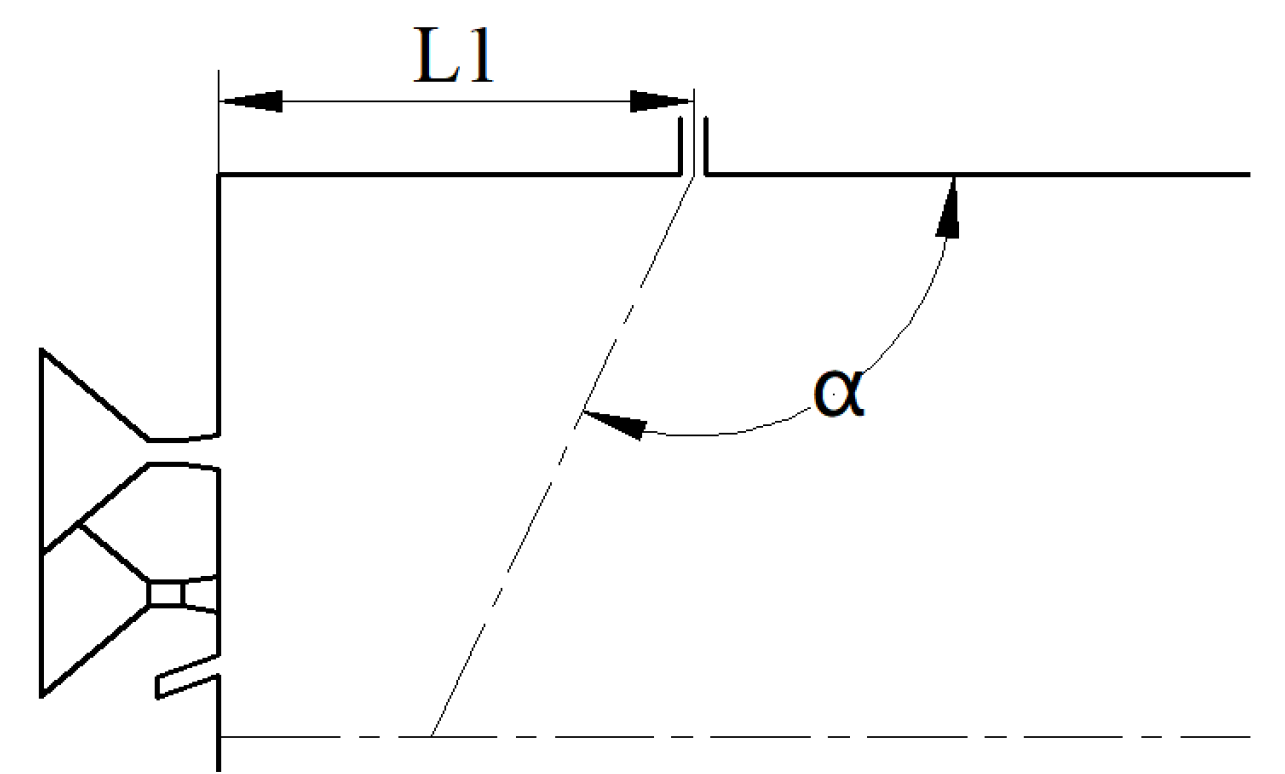
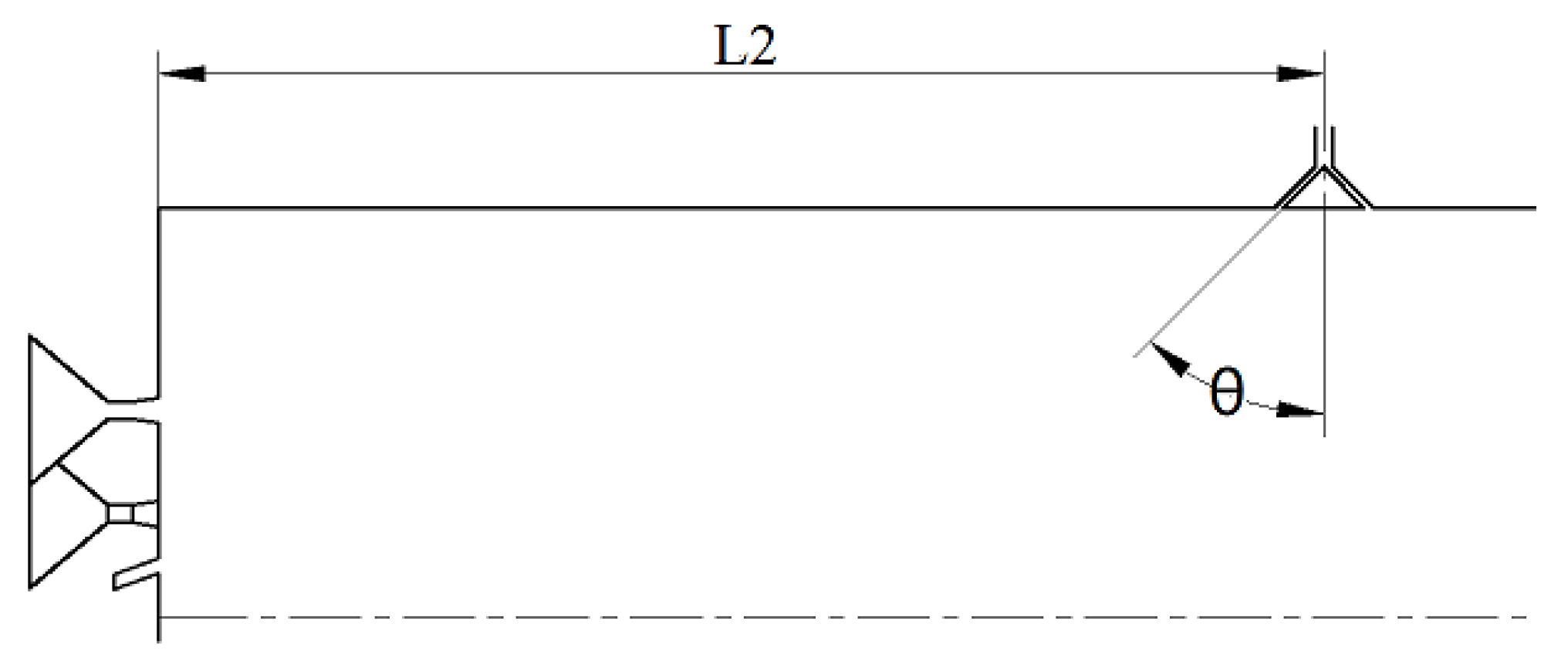
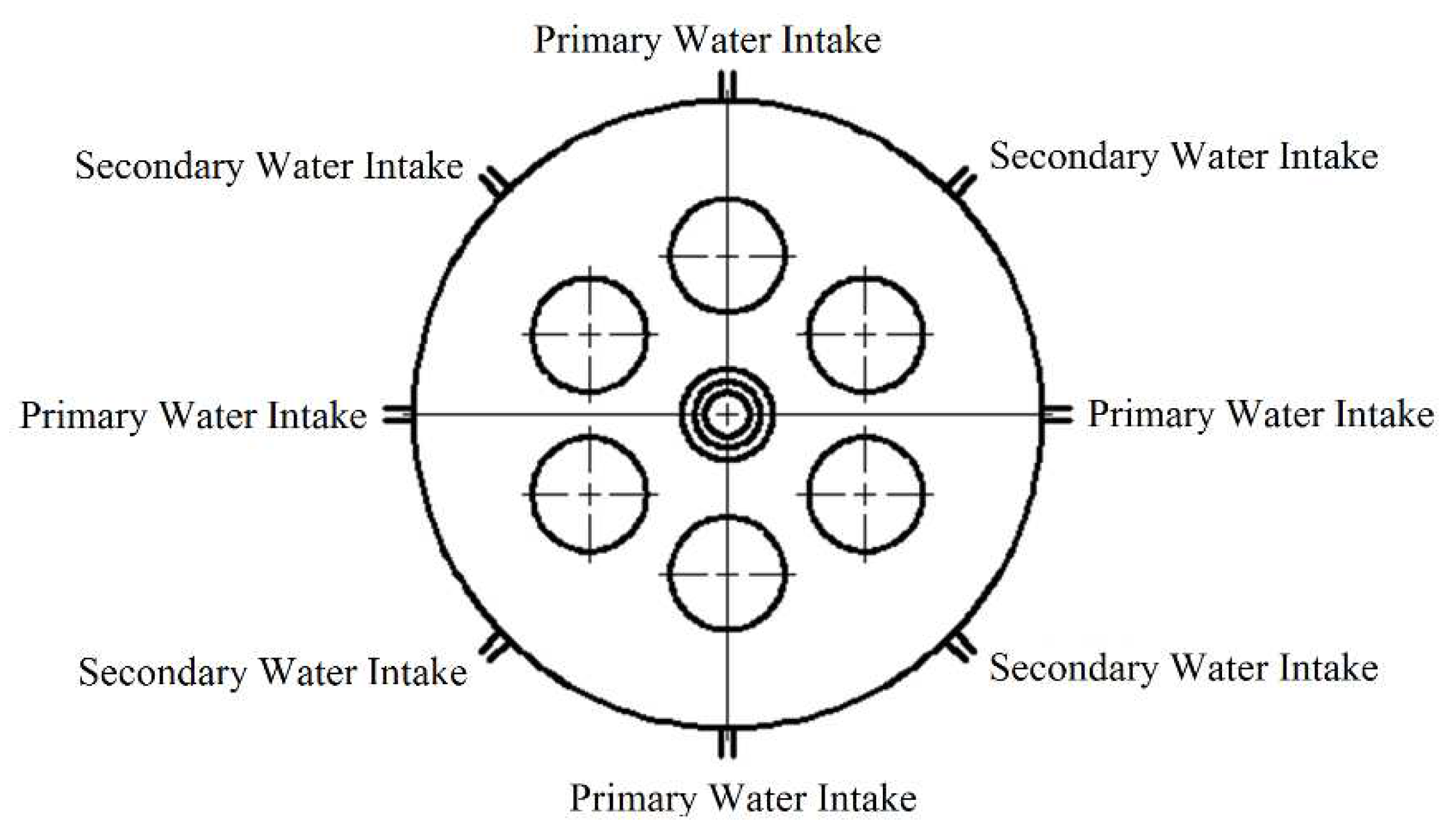
The schematic diagram of the water-driven engine combustion chamber to be analyzed is shown in Figure 1. The center of the engine head is the entrance for the powder, which is carried into the combustion chamber by the fluidized gas. The powder injector cone angle is 30°. There are also six evenly distributed ignition gas inlets at the top of the engine, which are high-temperature gas inlets. The combustion chamber has a diameter of 146 mm, and the replenishing chamber has a diameter of 108 mm. The length of the combustion chamber is 268 mm, and the length of the replenishing chamber is 450 mm. The throat diameter of the nozzle is 37.2 mm, and the nozzle outlet diameter is 74.2 mm. The water droplets are injected into the combustion chamber twice, with the first injection distance from the combustion chamber head being L1 mm and the second injection distance being L2 mm. Both injection ports are evenly distributed at four points and arranged in a 45° staggered layout (as shown in Figure 2). The first injection is a straight injection, with an injection angle of α° (as shown in Figure 3), and the second injection is a radial injection, with a cone angle of θ° (as shown in Figure 4). During engine operation, the high-temperature gas produced by the gas generator flows downstream after mixing with the high-temperature gas inlet. The water droplets are injected into the combustion chamber near the wall and mix with the mixture of high-temperature gas and magnesium particles, and the gas-solid two-phase flow mixes and burns. Magnesium reacts with water vapor produced by the evaporation of water, and further evaporates water droplets. The gas-solid two-phase products are ejected from the nozzle, generating thrust.

2.2. Basic assumptions

Due to the extremely complex flow structure of the water jet engine combustion chamber, the combustion flow is a three-dimensional two-phase turbulent combustion, and it is difficult to simulate all chemical reactions and consider all flow factors. In order to simplify the analysis, the following assumptions are adopted in the numerical calculation:
(1) The flow is a three-dimensional quasi-steady flow;
(2) The gas is an ideal gas, satisfying the ideal gas state equation, p=ρRT;
(3) A rebound model is used for the droplets on the solid wall, with a radial rebound coefficient of 0.7 and a tangential rebound coefficient of 0.6;
(4) In the calculation of the discrete trajectory of the movement, only the effect of the gas-phase drag force on the particles is considered, and the influence of other forces such as gravity and lift is ignored.

2.3. Governing Equations

The governing equations for the mass, momentum, energy, species transport, and k-ε turbulence model, as well as the transport equation for each species in Cartesian coordinate system, can be expressed in the following general form:
t ( ρ ϕ ) + t ( ρ u ) + t ( ρ v ) + t ( ρ w ) x ( Γ ϕ ϕ x ) y ( Γ ϕ ϕ y ) z ( Γ ϕ ϕ x ) = S ϕ
where ϕ represents the flow variable, Γ ϕ is the effective transport coefficient of variable ϕ , and S ϕ is the source term.

2.4. Magnesium-Water Reaction Model

Due to the high melting point of magnesium oxide at 3125K, magnesium oxide exists in solid phase in the combustion chamber of the water-jet propulsion engine. During the combustion process, flames emerge from surface cracks, and an oxide layer always exists on the surface of magnesium to protect it. To simplify the magnesium-water combustion model, after the temperature of magnesium reaches the ignition temperature, the oxide layer on the surface rapidly breaks, and the oxide layer combines with the magnesium oxide generated during combustion, and stays on the magnesium droplet in a unified form of a spherical cap. Magnesium exposed to the combustion chamber environment burns with water vapor through a diffusion-controlled gas-phase combustion process. The model uses the modified D2 law to describe the mass change of droplets, which is expressed as:
d m p d t = 4 π λ g r p C g ln [ 1 + C g ( T T b o i l ) q i l + h f g ]
where m p is the droplet mass, λ g and C g are the thermal conductivity and specific heat of the environment atmosphere, r p is the droplet radius, T and T b o i l are the environmental temperature and boiling point temperature, h f g is the latent heat of magnesium evaporation; and q i l is the heat absorbed by unit mass of fuel from the initial temperature to the surface temperature during combustion.

2.5. Boundary Conditions

In the calculation, the no-slip adiabatic wall condition is adopted, and the pressure and mass fraction gradients of each component are set to zero. The gas inlet flow rate of the engine is 0.2 kg/s, and the total temperature is 3000 K. The gas phase mass fraction in the combustion gas is 72%, with the main components being H2O, CO, and CO2, with mass fractions of 0.39, 0.11, and 0.50. The solid phase occupies 28%, mainly consisting of magnesium oxide. The magnesium powder flow rate is 0.8 kg/s, with a particle size of 10 μm, and the fluidizing gas flow rate is 0.04 kg/s. The total water flow rate is 2.4 kg/s, and the water droplet diameter is 500 μm. The initial temperature of both the magnesium powder and water droplets is 300 K.

2.6. Model Validation

The established calculation method is validated against experimental data using the engine configuration referred to in the literature. The engine inlet water flow rate is 60 g/s, and the water-to-fuel ratio is 0.77. The comparison between the calculated engine parameters and experimental data is shown in Table 1. It can be seen from the table that the error between the simulation results and experimental data is less than 10%, which meets the project index requirements.

3. Results and Discussion

3.1. Effect of Water Injection Position

By changing the positions of the primary and secondary water injections, the mixing of water and high-temperature gases and the evaporation rate of water in the engine can be affected. Therefore, it is necessary to study the effect of water injection position. In the simulation, the flow rate of the primary water injection is 0.4 kg/s, and the angle is 90°, while the flow rate of the secondary water injection is 2 kg/s and the half cone angle is 45°. The simulation conditions and results are shown in Table 2. The results show that changing the position of the primary water injection has a small influence on the flow field inside the engine, and there is no significant difference in the engine's pressure and the temperature at the entrance of the afterburner. However, there is still an optimal water injection position, and moving the primary water injection closer or further away from the head of the combustion chamber will result in a slight reduction in engine performance. The distance of the secondary water injection has a more significant effect on the engines performance, and the engines performance improves as the position of the secondary water injection is reduced.
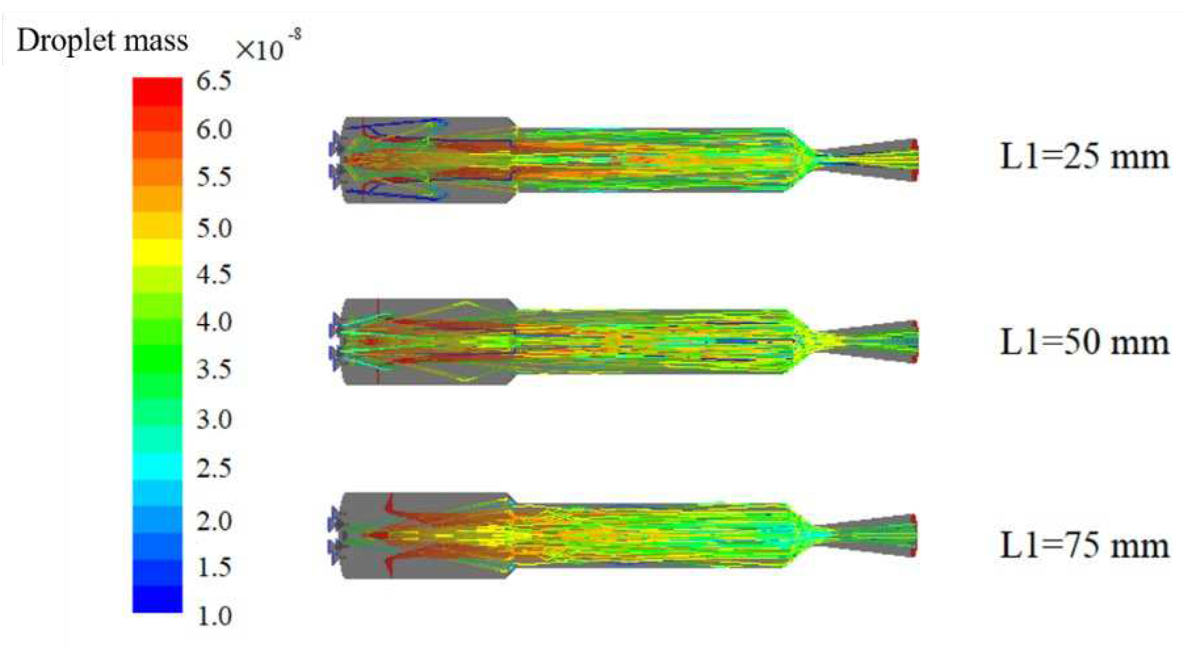
Figure 5 shows the variation of water droplet mass along the trajectory under different positions of the first water injection. It is observed that as the first injection position moves backward, the number of water droplets entering the head region of the combustion chamber decreases significantly, with a similar droplet vaporization rate, and most of them are still ejected from the nozzle in liquid form. As the gas flow is obstructive, a high velocity generates a recirculation zone at the head of the combustion chamber, which entrains some water droplets into the recirculation zone. The closer the first injection position is to the head of the combustion chamber, the more water droplets enter the recirculation zone, leading to intense mixing between the water droplets and the high-temperature gas and resulting in significant water evaporation at the head of the combustion chamber.
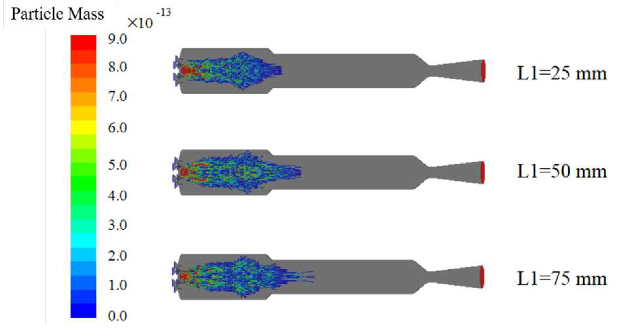
Figure 6 shows the variation of magnesium particle mass along the trajectory under different locations of the primary water injection. Due to the small particle size of the injected magnesium, it can be fully consumed near the entrance of the secondary combustion chamber.
As the position of the primary injection moves forward, higher concentrations of water vapor appear in the head region of the combustion chamber, promoting the reaction between magnesium and water and increasing the reaction rate. A higher reaction rate leads to a significant exothermic process in the head region of the combustion chamber, which increases the temperature of the magnesium particles and thus promotes their consumption.
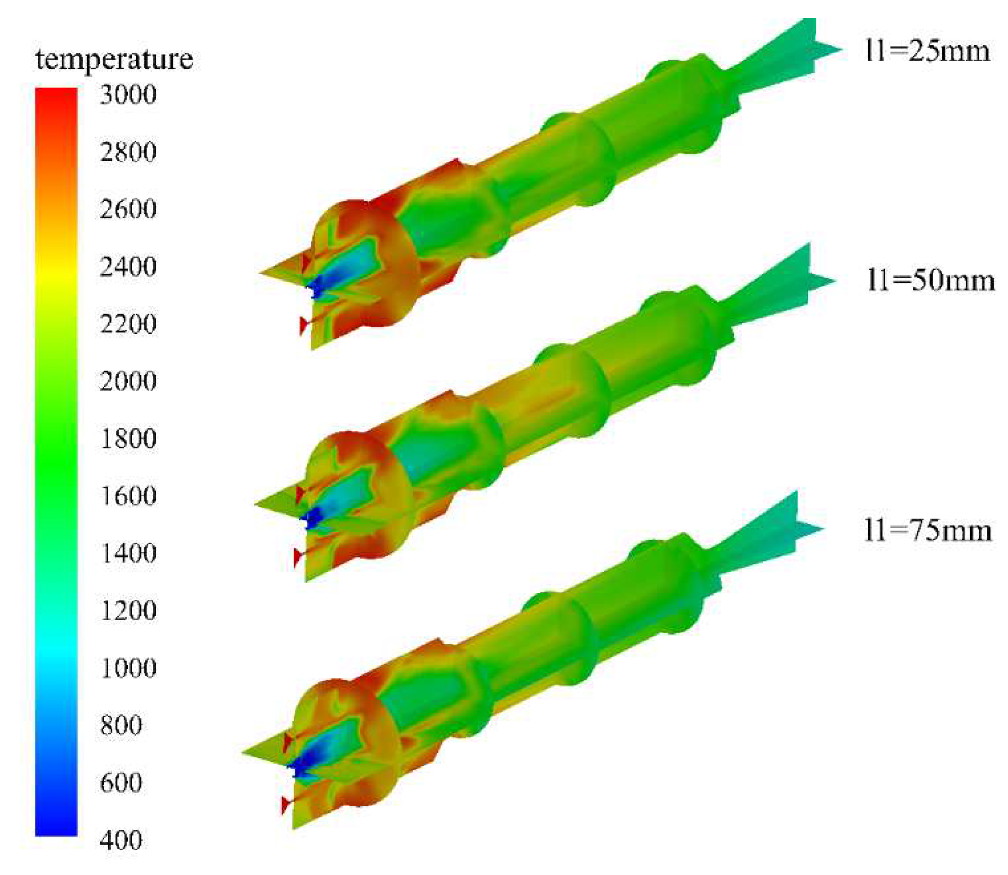
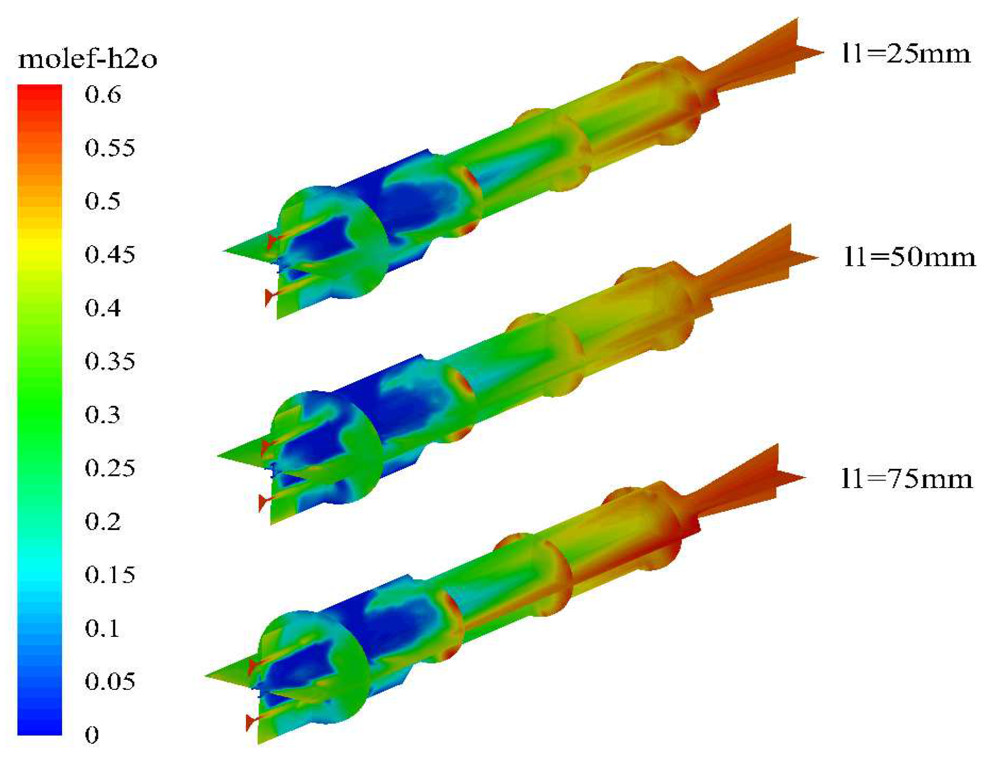
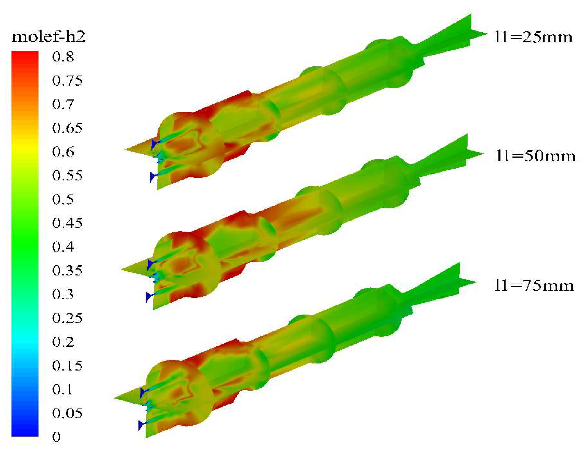
Figure 7, Figure 8 and Figure 9 show the temperature and molar fraction of water vapor and hydrogen gas under different water injection conditions. The high-temperature region inside the engine is mainly concentrated in the head area of the combustion chamber, where the downstream of the water injection port has a higher temperature. As the powders are entrained into the chamber by the ambient gas at room temperature, there exists a relatively low-temperature zone in the central region of the head of the combustion chamber. With the water injection port moving forward, the position of the magnesium-water reaction will be closer to the head of the combustion chamber, resulting in a rapid increase in the temperature of the fluidized gas. Similarly, a relatively low-temperature region exists in the central area of the aft part of the combustion chamber, mainly due to the large amount of secondary water injection, which absorbs heat through high-temperature evaporation. As a significant amount of magnesium has been consumed in the head of the combustion chamber, the remaining magnesium content is reduced, resulting in a lower heat release from the magnesium-water reaction compared to the heat absorbed by the evaporation of water. Therefore, this region experiences a temperature drop.
The contour maps of water vapor concentration distribution indicate that there are still large areas of low concentration in the combustion chamber, while the concentration of water vapor continues to increase in the post-combustion chamber. This is mainly due to the large amount of magnesium particles evaporating in the head of the combustion chamber, which react with water vapor and are completely consumed. However, magnesium particles are almost completely consumed in the combustion chamber, and there is a relatively high temperature at the inlet of the post-combustion chamber, causing a large amount of unevaporated water to begin evaporating in the post-combustion chamber, thereby increasing the mole fraction of water in the post-combustion chamber. The distribution characteristics of the mole fraction of hydrogen gas are opposite to those of water. Since hydrogen gas is the only gaseous product generated by the reaction between magnesium and water, this further indicates that the magnesium-water reaction mainly occurs in the combustion chamber. In the post-combustion chamber, as magnesium is completely consumed, only water evaporates, and as the content of water vapor increases, the mole fraction of hydrogen gas in the post-combustion chamber begins to gradually decrease.
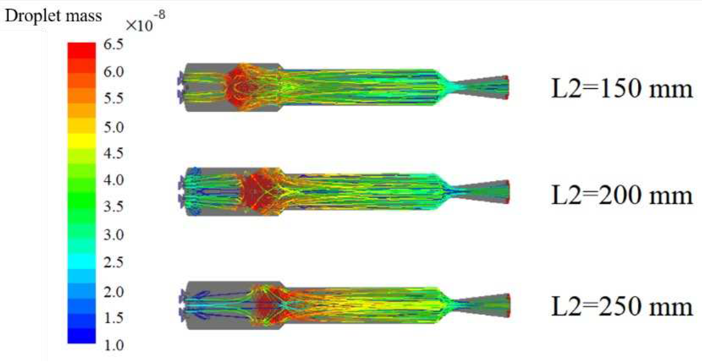
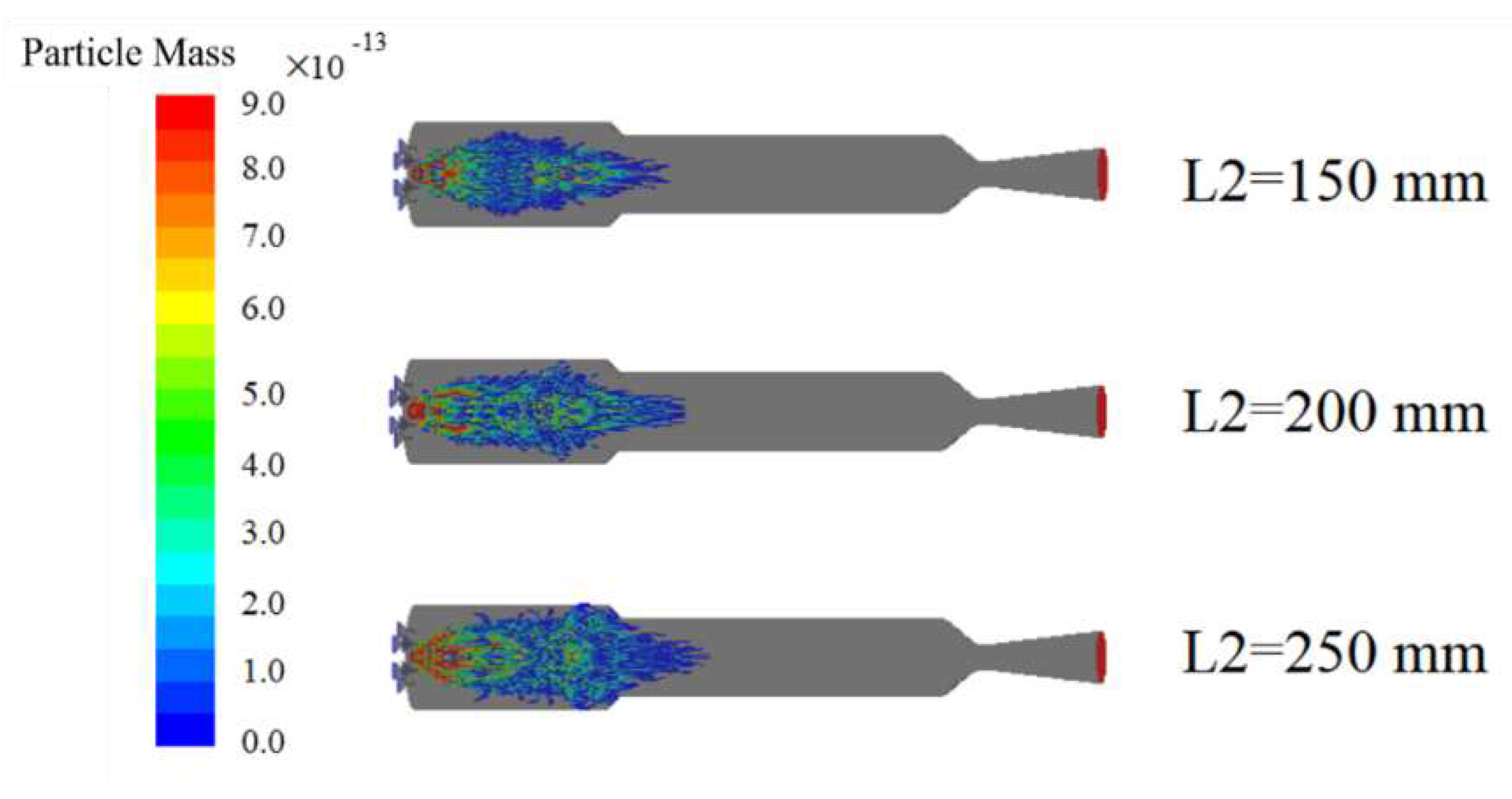
Figure 10 and Figure 11 show the variation of water droplet and magnesium particle mass along the trajectory under different conditions of the secondary air inlet distance. Due to the expansion angle of the secondary air inlet, a certain amount of water droplets enter the head area of the combustion chamber. As the head distance decreases, the residence time of water droplets in the head region increases, leading to an increase in the consumption rate of water in the head of the combustion chamber with an increase in L2. However, when L2 is greater than 200 mm, the amount of water droplets diffusing to the head of the combustion chamber is significantly reduced due to the influence of airflow. Additionally, when the secondary air inlet distance is large, the residence time of water droplets spraying downstream in the afterburning chamber is shortened, leading to a reduced phase change rate of water, decreased working fluid output, and reduced engine performance. Although the consumption rate of magnesium is reduced when L2=250 mm due to the lower water content diffusing to the head of the combustion chamber, complete consumption of magnesium can still occur in the upstream area of the afterburning chamber.
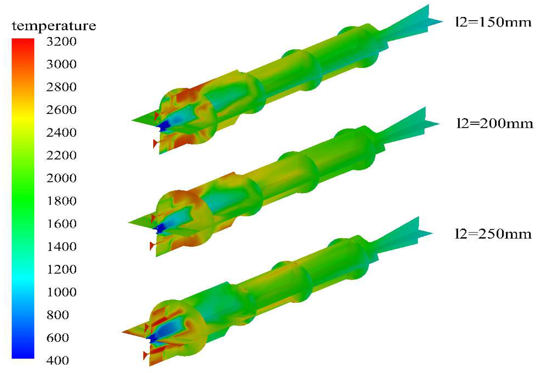
The temperature, water vapor and hydrogen mole fraction under different conditions of secondary water injection are shown in Figure 12, Figure 13 and Figure 14. The high temperature zone in the engine is mainly concentrated in the head area of the combustion chamber, and the high temperature zone decreases first and then increases with the increase of the secondary water injection distance. When the secondary water injection distance is short, although a large amount of water diffuses to the head of the combustion chamber, the short residence time does not cause significant evaporation cooling. In addition, the water vapor provided by the secondary water injection can promote the magnesium-water reaction and increase the temperature in the head area of the combustion chamber. However, when the secondary water injection distance is too large, although less water is provided, the evaporation cooling phenomenon of the head water droplets is slowed down, and the water droplets entering the head of the combustion chamber can stay for a long time, providing water vapor to promote the magnesium-water reaction and increase the temperature.
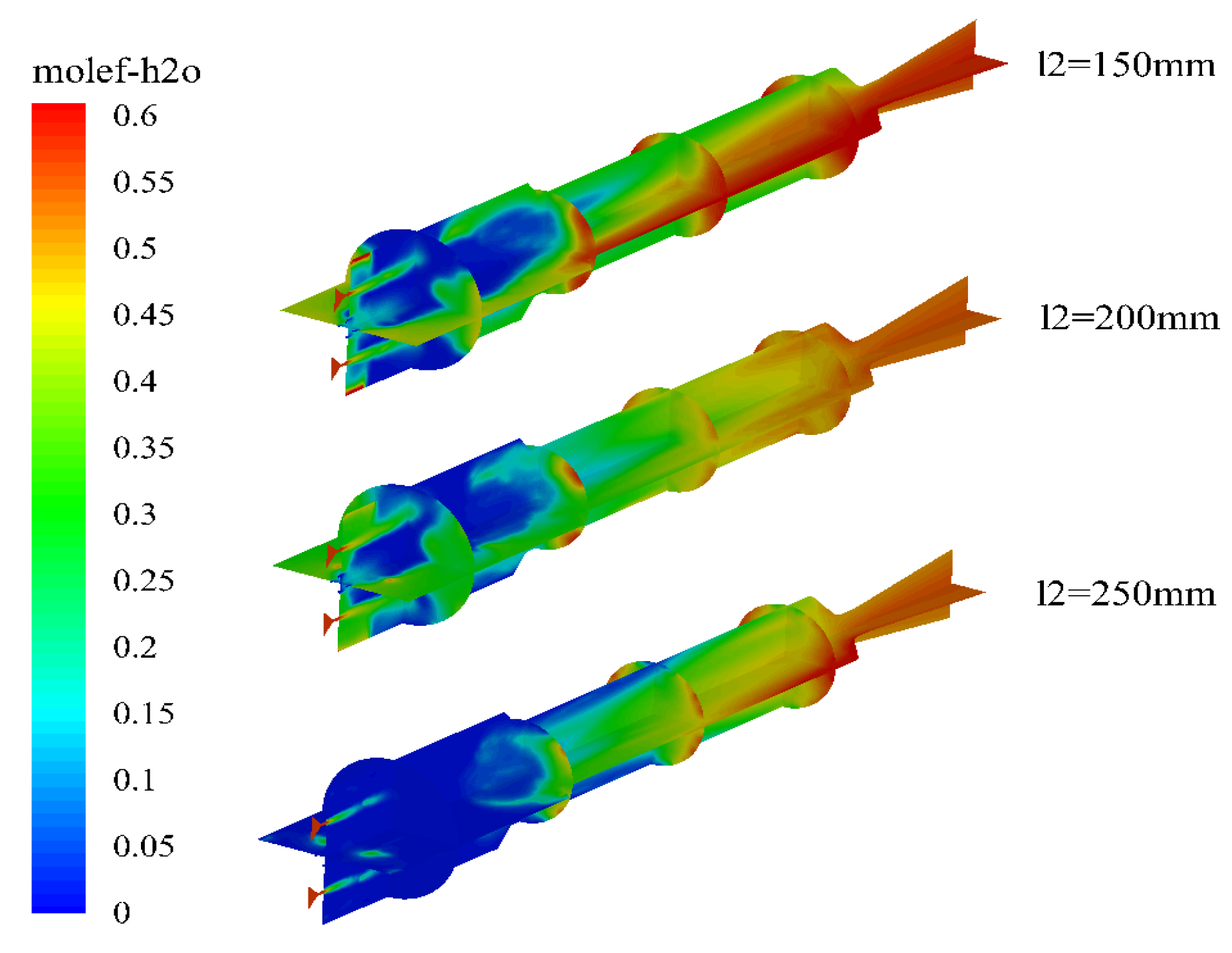
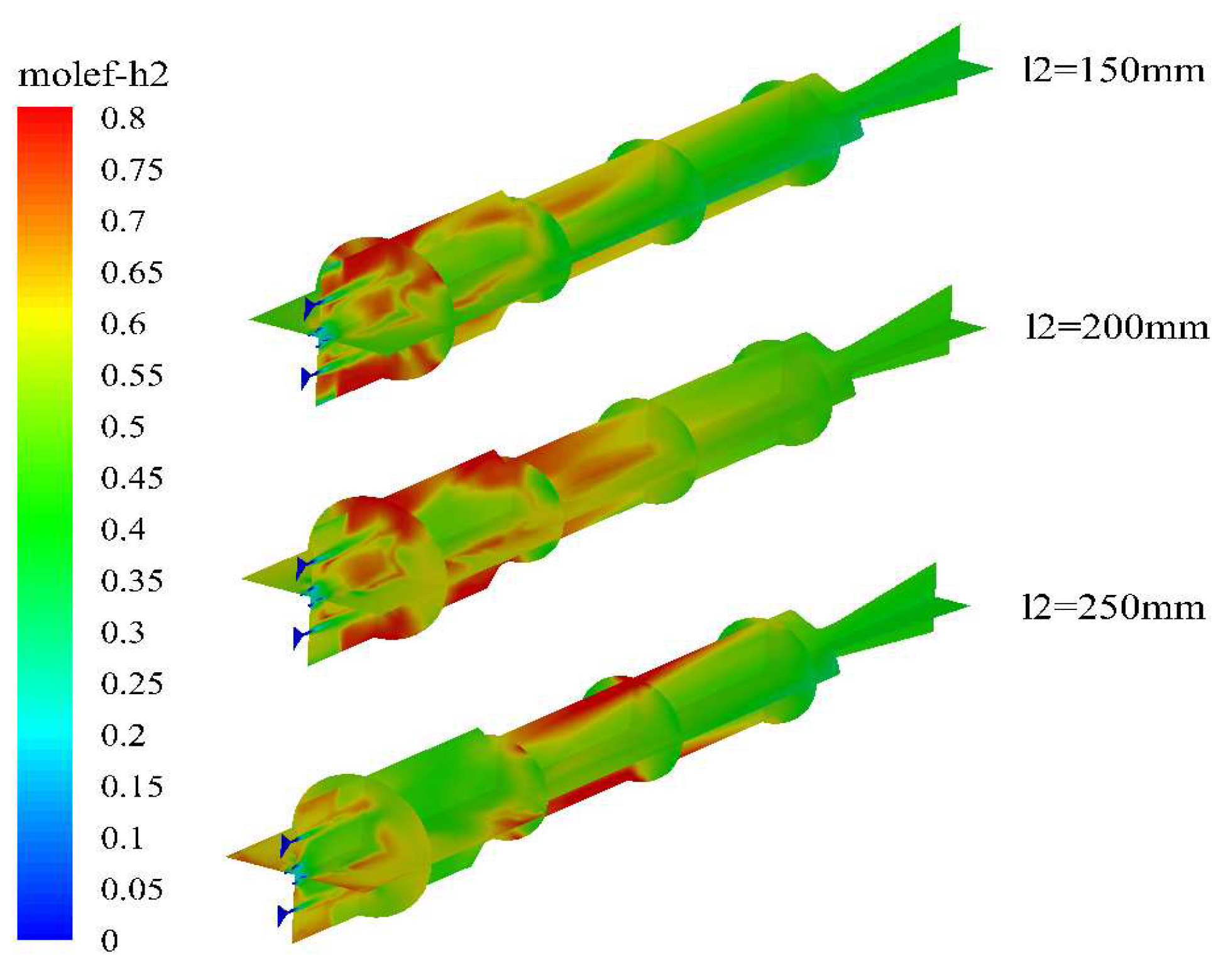
By comparing the molar fractions of water vapor in the combustion chamber under different secondary injection positions, it can be observed that as the secondary injection distance increases, the water vapor content in the combustion chamber decreases significantly. When L2 is 250 mm, the water content in the combustion chamber is almost zero, indicating that the head region of the combustion chamber is in lean combustion. The distribution map of hydrogen molar fraction shows that when L2 is less than 200 mm, there is a high concentration region of hydrogen in the combustion chamber. However, when L2 is 250 mm, this region has moved to the upstream region of the reheat chamber, indicating that excessively large secondary injection distances can result in incomplete combustion of magnesium water in the combustion chamber.

3.2. The law of the influence of the angle of primary water intake

By changing the angle of the first water injection, the mixing effect of water and high-temperature gas is also affected, and the evaporation rate of water inside the engine is changed. Therefore, it is necessary to study the impact of the first water injection angle. In the calculation process, the first water injection flow rate is 0.4 kg/s, L1=50 mm, the second water injection flow rate is 2 kg/s, L2=200 mm, and the half cone angle is 45°. The calculated conditions and results are shown in Table 3. The results show that changing the first water injection angle has a small impact on the flow field inside the engine, and there is no significant difference in engine pressure and temperature at the entrance of the combustor. However, there is still an optimal first water injection angle. Although the impact of the first water injection angle on engine performance is small, it has a significant impact on the temperature at the entrance of the engine's combustion chamber. This is mainly because the water injection angle affects the location of the magnesium-water reaction in the combustion chamber, which in turn changes the temperature at the entrance of the combustor.
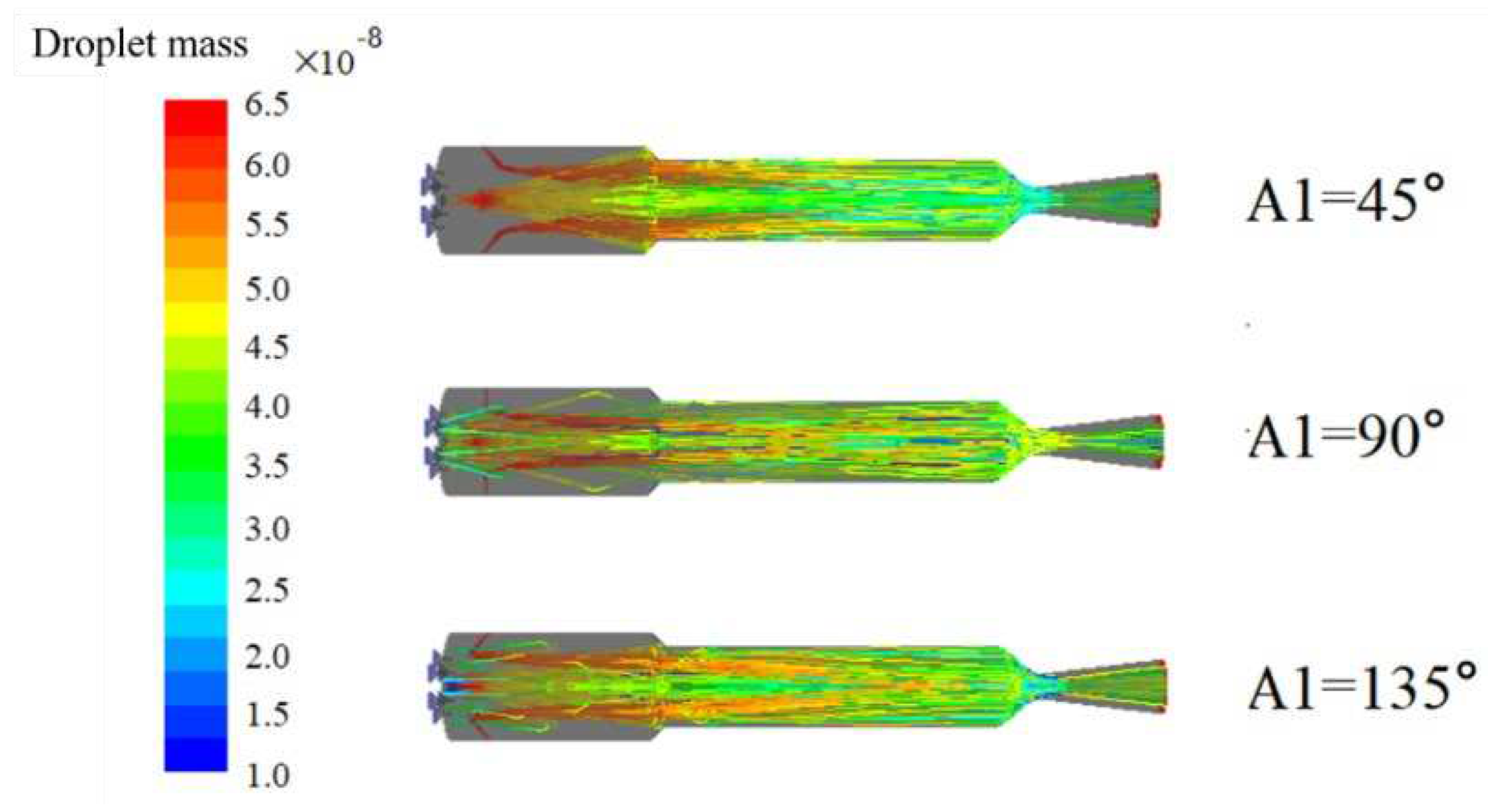
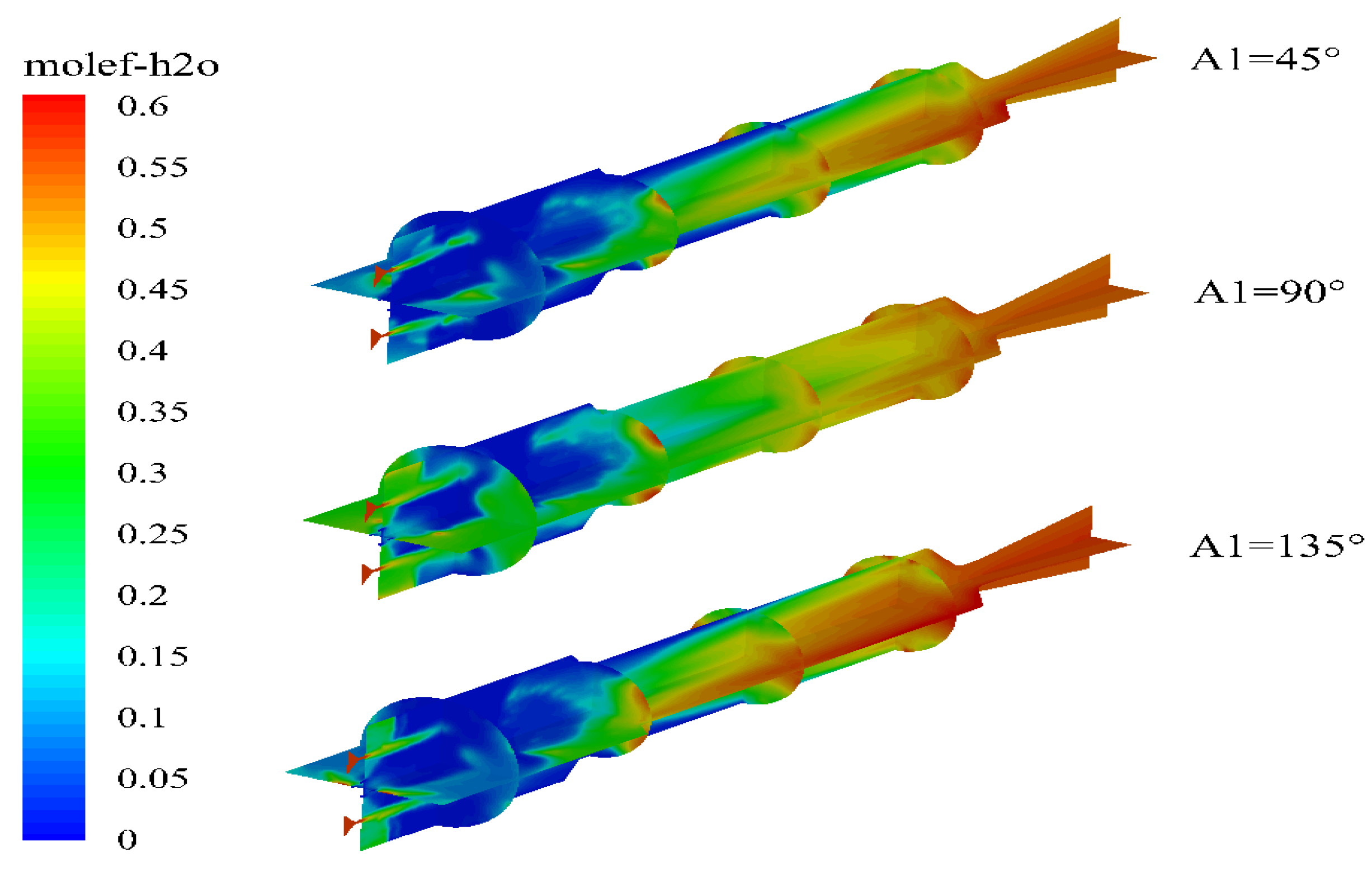
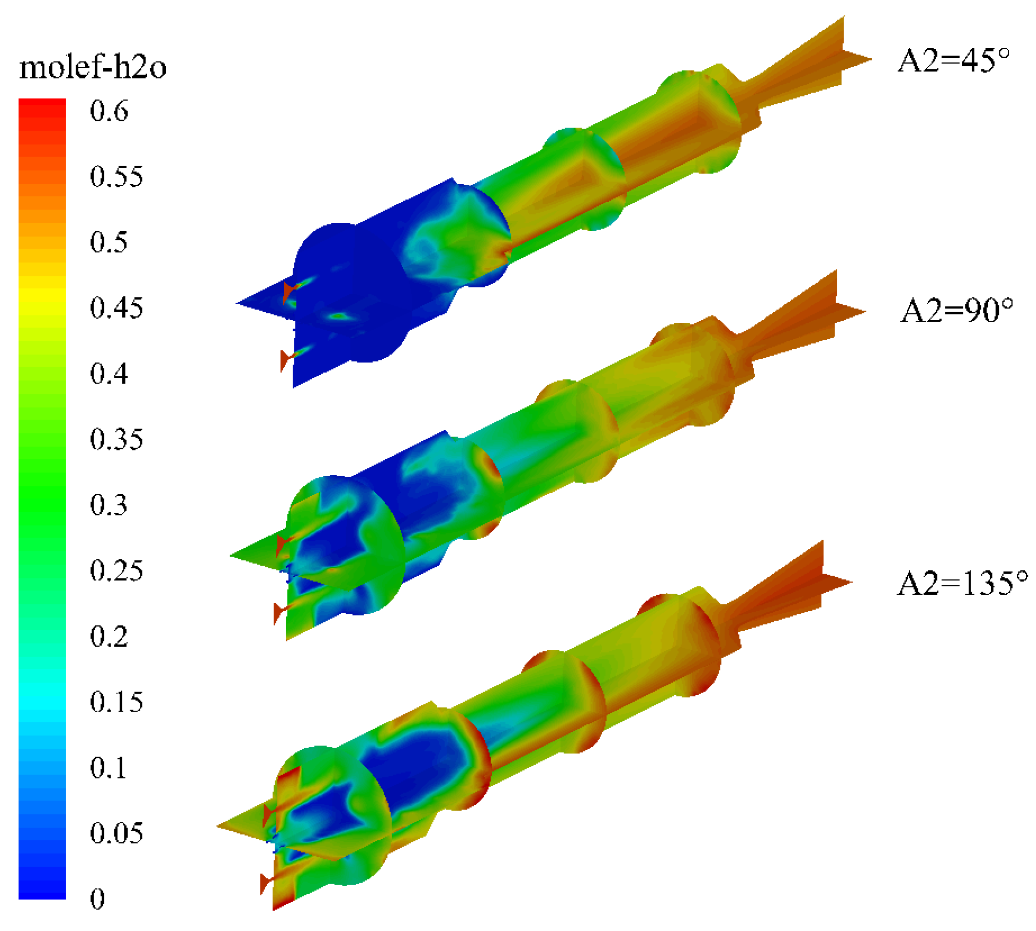
Figure 15 shows the mass of water droplets along their trajectories in the combustion chamber under different angles of primary injection. The results indicate that the flow behavior of water droplets in the combustion chamber varies significantly with changes in the injection angle. When the injection angle A1 is less than 90°, all of the water droplets from the primary injection flow downstream towards the exit of the combustion chamber. However, as the injection angle increases, some water droplets begin to flow towards the head of the combustion chamber. Figure 16 presents the distribution of water vapor mole fraction in the engine under different angles of primary injection. It is observed that both too large and too small injection angles lead to a decrease in water vapor content at the head of the combustion chamber. In the case of small injection angles, this is mainly due to the flow direction of the water droplets. For larger injection angles, a large number of water droplets are trapped in the head of the combustion chamber, which increases the amount of water but also leads to a decrease in the temperature of the combustion chamber due to the endothermic process of water evaporation. Consequently, the rate of water evaporation is reduced, leading to lower water concentration in the combustion chamber.
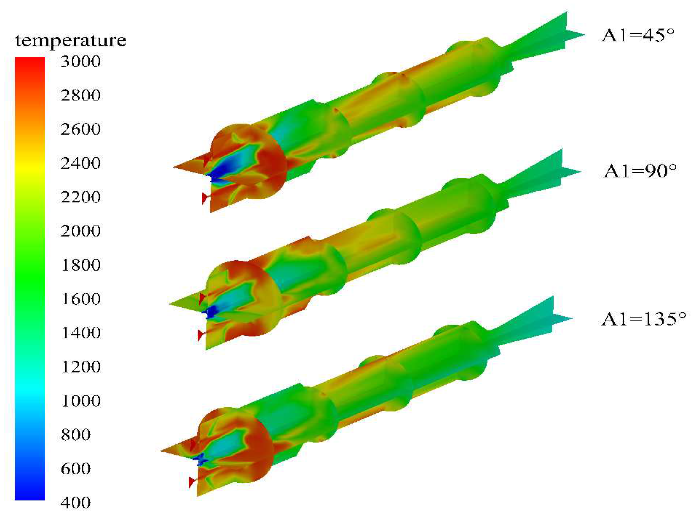
Figure 17 shows the temperature distribution in the engine for different first injection angles. It can be observed that the temperature distribution in the head region of the combustion chamber is roughly equivalent for all cases. However, when the first injection angle is 90°, the water spreads uniformly before and after the injection, resulting in simultaneous occurrence of magnesium-water reactions and water evaporation, leading to uniform temperature distribution. For excessively small or large first injection angles, there are significant high-temperature zones in the reheat chamber, indicating poor mixing of magnesium in the combustion chamber and incomplete combustion.

3.3. Effect of Second Inlet Expansion Angle

By changing the expansion angle of the second inlet, the diffusion of the water spray towards the head of the combustion chamber and the water-to-fuel ratio at the head of the combustion chamber are influenced, which, in turn, affects the engine performance. In the calculation process, the flow rate of the first inlet is 0.4 kg/s, L1=50 mm, and the first inlet angle is 90°. The flow rate of the second inlet is 2 kg/s, L2=200 mm. The calculation conditions and results are shown in Table 4. The results show that changing the half-cone angle of the second inlet has a significant effect on the inlet temperature of the engines afterburner chamber. The larger the cone angle, the more intense the water diffuses towards the head of the combustion chamber, which increases the heat absorbed by water evaporation and, in turn, decreases the inlet temperature of the afterburner chamber.
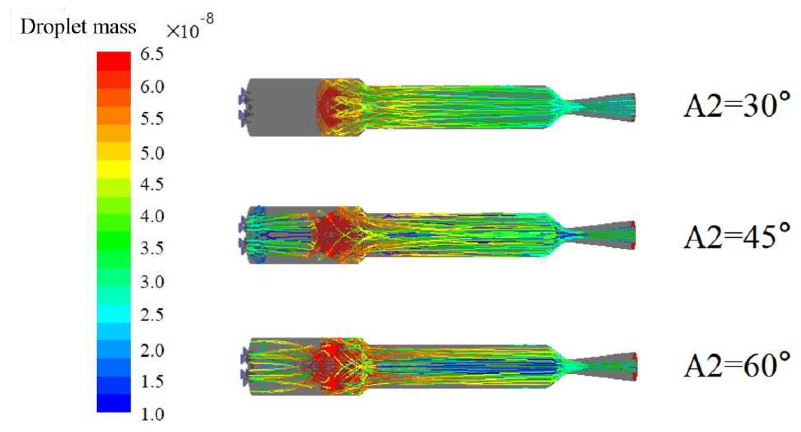
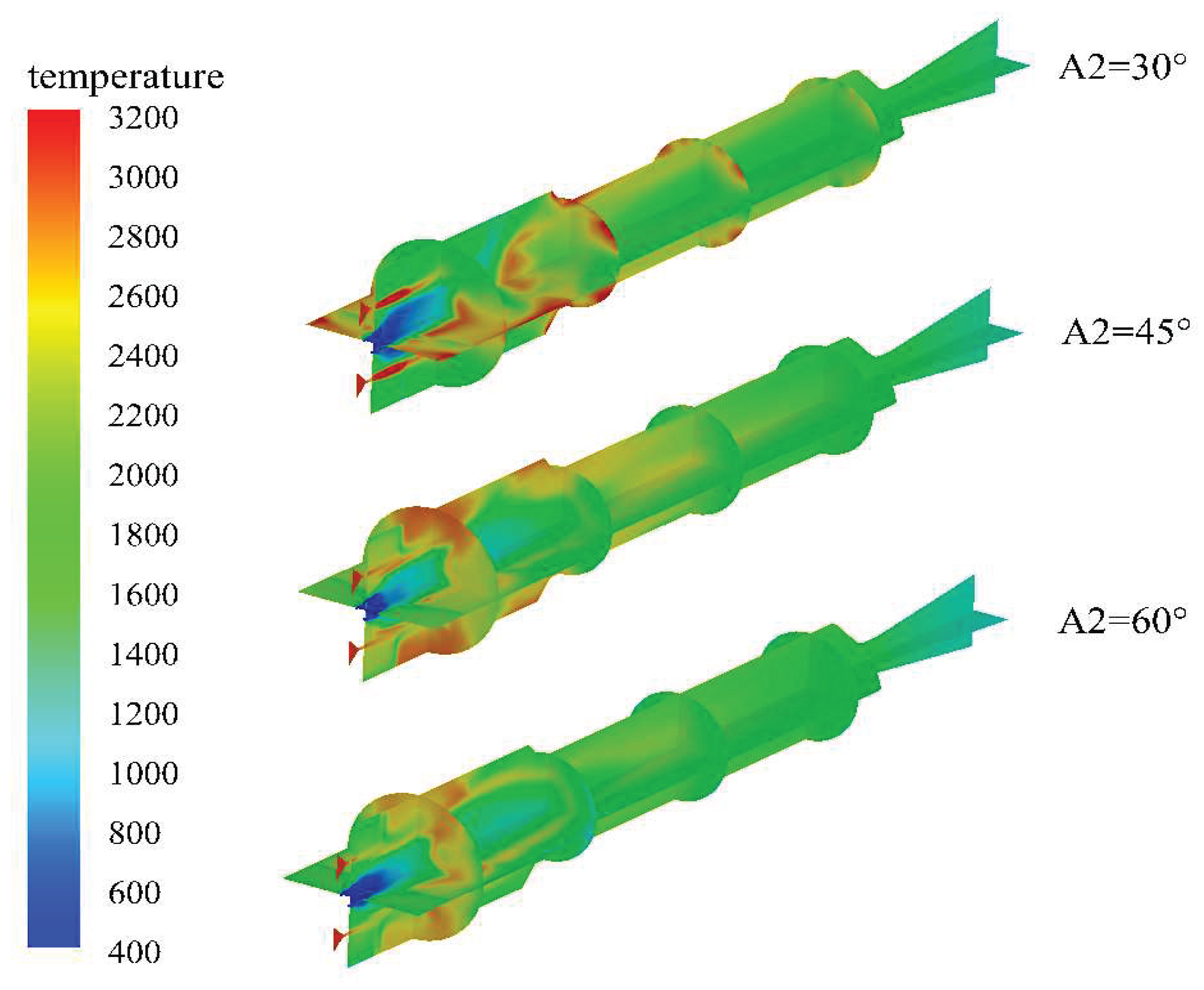
Figure 18 and Figure 19 show the variation of water droplet mass along the trajectory and the distribution of water vapor mole fraction inside the engine, respectively, under different half cone angles of the secondary injection. It can be observed that as the half cone angle of the secondary injection increases, the amount of water droplet spreading towards the head of the combustion chamber increases, but the evaporation rate at the head of the chamber decreases. This is mainly due to the fact that with the increase of the angle, the water droplets are subjected to an increase in velocity component in the axial direction, and they possess higher momentum, which reduces their residence time at the head. In addition, the increase in water amount raises the heat absorption of evaporation, leading to a decrease in temperature at the head of the combustion chamber, which also slows down the evaporation rate of water droplets in the head region.
Figure 20 shows the temperature distribution inside the engine under different half-cone angles of secondary injection. It can be observed that at smaller half-cone angles, the gas injection temperature is higher, indicating a better mixing effect between gas and magnesium powder. In the head region of the combustion chamber, there are mainly three processes: magnesium-water reaction, water evaporation, and magnesium powder gasification. Due to the low water flow rate of primary injection, there is a lean combustion in the head region. However, after mixing with the secondary injection, the high-temperature gas containing magnesium in the gas phase efficiently mixes with the secondary injection. The magnesium-water reaction proceeds rapidly in the gas phase and forms a high-temperature region at the entrance of the combustion chamber. Meanwhile, this high-temperature region allows the secondary injection to obtain a higher initial temperature before entering the combustion chamber, significantly increasing the water vapor concentration in the combustion chamber. This is also beneficial for improving the engine performance.

4. Conclusion

In this study, the influence of different water injection schemes on the performance of a solid-magnesium powder water-jet engine was investigated. The following conclusions were drawn:
(1) The high temperature gas in the combustion chamber contains a large amount of water vapor, which can promote the vigorous combustion of magnesium powder in the head of the combustion chamber, releasing a large amount of heat and promoting the evaporation of the primary water injection.
(2) An excessively large distance of the primary water injection can result in a lack of oxidant in the head of the combustion chamber, significantly reducing the temperature of the head of the combustion chamber. Conversely, an excessively small distance of the primary water injection can result in the presence of a high-temperature region in the head of the combustion chamber due to vigorous reaction, which is not conducive to engine thermal protection.
(3) The structure of the secondary water injection has a significant influence on the heat release characteristics of the magnesium powder. A small diffusion of the secondary water injection towards the head of the combustion chamber can result in a lean combustion in the head of the combustion chamber, while a larger diffusion can result in a reduction in the temperature of the head of the combustion chamber.
Overall, this study provides important insights into the performance optimization of solid-magnesium powder water-jet engines, which could potentially lead to improved engine efficiency and durability.

Acknowledgments

This work was financially supported by the China Postdoctoral Science Foundation (Grant No. 2019TQ0246, 2019M663734), the National Science Basic Research Program of Shaanxi (Program No. 2022JM-231).

Conflicts of Interest

The authors declare that there is no conflict of interest.

References

  1. Tahsini A M, Ebrahimi M. Increasing Isp by injecting water into combustion chamber of an underwater SRM [C]. AIAA 2006-4959.
  2. SUN Zhiyue, DENG Fei, ZHANG Bo. Working characteristics of inlet channel of metal/water ramjet engine[J]. Computer Simulation 2011, 28, 28–31.
  3. Greiner, L. Selection of High Preformance Propellants for Torpedoes [J]. ARS J. 1960, 1161–1163. [Google Scholar] [CrossRef]
  4. Stinbring D R, Cook R B, Dzielski J E, et al. High-Speed Supercavitating Vehicles [C]. AIAA 2006-6441.
  5. Bucher P, Yetter R A, Dryer F L, et al. PLIF species and ratiometric temperature measurements of aluminum particle combustion in O2, CO2 and N2O oxidizers, and comparison with model calculations [J]. Symposium (International) on Combustion 1998, 27, 2421–2429. [Google Scholar] [CrossRef]
  6. Dreizin E, L. On the mechanism of asymmetric aluminum particle combustion [J]. Combustion and Flame 1999, 117, 841–850. [Google Scholar] [CrossRef]
  7. Bucher P, Yetter R A, Dryer F L, et al. Flames structure measurement of single, isolated aluminum particles burning in air [J]. Symposium (International) on Combustion 1996, 26, 1899–1908. [Google Scholar] [CrossRef]
  8. Dreizin E, L. Experimental study of stages in aluminum particle combustion in air [J]. Combustion and Flame 1996, 105, 541–556. [Google Scholar] [CrossRef]
  9. Ross H D, Gollahalli S R. Microgravity combustion fire in free fall [J]. Applied Mechanics Reviews 2002, 55, B116. [Google Scholar] [CrossRef]
  10. Beckstead M, W. Correlating aluminum burning times [J]. Combustion Explosion and Shock Waves 2005, 41, 533–546. [Google Scholar] [CrossRef]
  11. Al'tman I S, Vovchuk Y I. Thermal regime of the vapor-state combustion of a magnesium particle [J]. Combustion, Explosion, and Shock Waves 2000, 36, 227–229. [Google Scholar] [CrossRef]
  12. Florko A V, Zolotko A N, Kaminskaya N V, et al. Spectral investigation of the combustion of magnesium particles [J]. Combustion, Explosion and Shock Waves 1982, 18, 17–22. [Google Scholar]
  13. Dreizin E L, Hoffmann V K. Experiments on magnesium aerosol combustion in microgravity [J]. Combustion and Flame 2000, 122, 20–29. [Google Scholar] [CrossRef]
  14. Dreizin E L, Berman C H. Condensed-phase modifications in magnesium particle combustion in air [J]. Combustion and Flame 2000, 122, 30–42. [Google Scholar] [CrossRef]
  15. Prachukho V P, Ozerov E S, Yurinov A A. Burning of magnesium particles in water vapor [J]. Combustion, Explosion and Shock Waves 1971, 7, 232–236. [Google Scholar]
Figure 1. Structure diagram of refueling chamber (mm).
Preprints 71042 g001
Figure 2. Layout of the circumferential position of the inlet channel.
Preprints 71042 g002
Figure 3. Schematic diagram of the angle of primary water intake.
Preprints 71042 g003
Figure 4. Schematic diagram of the angle of the secondary inlet cone.
Preprints 71042 g004
Figure 5. The mass of water droplets changes with the trajectory under different inlet distances.
Preprints 71042 g005
Figure 6. Variation of magnesium particle mass with trajectory under different inlet distances.
Preprints 71042 g006
Figure 7. Temperature distribution in the engine under different primary water inlet distances.
Preprints 71042 g007
Figure 8. Distribution of molar fraction of water vapor in engine under different primary water inlet distances.
Preprints 71042 g008
Figure 9. Distribution of hydrogen molar fraction in engine under different primary water inlet distances.
Preprints 71042 g009
Figure 10. Variation of water droplet mass with trajectory under different inlet distances.
Preprints 71042 g010
Figure 11. Variation of magnesium particle mass with trajectory under different primary water inlet distances.
Preprints 71042 g011
Figure 12. Temperature distribution in the engine under different secondary water inlet distances.
Preprints 71042 g012
Figure 13. Distribution of molar fraction of water vapor in engine under different secondary water inlet distances.
Preprints 71042 g013
Figure 14. Distribution of hydrogen molar fraction in engine under different secondary inlet distances.
Preprints 71042 g014
Figure 15. Variation of water droplet mass with trajectory under different inlet angle conditions.
Preprints 71042 g015
Figure 16. Distribution of molar fraction of water vapor in engine under different primary water intake angles.
Preprints 71042 g016
Figure 17. Cloud map of temperature distribution in the engine under different primary water inlet angles.
Preprints 71042 g017
Figure 18. Variation of water droplet mass with trajectory under different secondary inlet half-cone angle conditions.
Preprints 71042 g018
Figure 19. Distribution of molar fraction of water vapor in engine under different secondary water inlet half-cone angle conditions.
Preprints 71042 g019
Figure 20. Temperature distribution cloud in the engine under different secondary water inlet half-cone angles.
Preprints 71042 g020
Table 1. Comparison between experimental and numerical simulation.
Parameter Experimental numerical simulation
Combustion chamber pressure / MPa 1.52 1.50
Combustion chamber temperature / K / 1114
Characteristic velocity / m/s 864.3 847.6
Combustion efficiency /% 68.7 67.4
Table 2. Engine flow field and performance parameters under different water inlet positions.
Working conditions L1
mm
L2
mm
inlet temperature of the make-up chamber / K Pressure / MPa Characteristic velocity / m/s
1 25 200 2639.1 2.53 2644.7
2 50 200 2589.9 2.55 2665.5
3 75 200 2601.3 2.54 2658.2
4 50 150 2369.2 2.56 2678.0
5 50 250 2060.4 2.50 2611.4
Table 3. Engine flow field and performance parameters under different primary water inlet angles.
Working conditions A1 inlet temperature of the make-up chamber / K Pressure / MPa Characteristic velocity / m/s
1 45 1761.6 2.53 2646.7
2 90 2589.9 2.55 2665.5
3 135 2225.2 2.54 2658.2
Table 4. Engine flow field and performance parameters under different secondary water inlet expansion angles.
Working conditions A2 inlet temperature of the make-up chamber / K Pressure / MPa Characteristic velocity / m/s
1 30 3103.2 2.56 2674.8
2 45 2589.9 2.55 2665.5
3 60 1971.0 2.54 2660.3
Disclaimer/Publisher’s Note: The statements, opinions and data contained in all publications are solely those of the individual author(s) and contributor(s) and not of MDPI and/or the editor(s). MDPI and/or the editor(s) disclaim responsibility for any injury to people or property resulting from any ideas, methods, instructions or products referred to in the content.
Copyright: This open access article is published under a Creative Commons CC BY 4.0 license, which permit the free download, distribution, and reuse, provided that the author and preprint are cited in any reuse.
Prerpints.org logo

Preprints.org is a free preprint server supported by MDPI in Basel, Switzerland.

Subscribe

© 2024 MDPI (Basel, Switzerland) unless otherwise stated