1. Introduction
The term bio-fouling means that undesirable phenomenon which leads to the growth of marine micro-organisms on all those surfaces immersed in the sea, from boats to oil platforms, to submarine pipes, etc. [
1,
2,
3]. The biofouling phenomenon of surfaces immersed in sea water begins with the adhesion of small bacterial species (microfouling) which grow forming a biofilm caused both by the multiplication of bacterial cells and by the synthesis of extracellular polymeric substances thanks to the presence of specific soluble organic substances in an aqueous environment (macrofouling) [
4].
The progressive depositing of marine micro-organisms creates an economic and environmental problem if specific antifouling paints are used which contain biocides which are not environmentally friendly and therefore harmful to marine ecosystems [
5,
6].
Other problems for the marine environment are related to the higher fuel consumption in the boats with higher marine organism adhesion to maintain their speed of movement compared to the boats without fouling [
7].
The biocides on the market are very effective because they effectively hinder the proliferation of the marine organisms in question, but at the same time they also indirectly destroy all the other marine organisms, with serious environmental damage [
8,
9].
The coatings with biocides of the "underground" parts, i.e. immersed in the sea, of the naval industry are typically based on silicone, polyurethane, epoxy resin, etc. [
10,
11,
12,
13]. The coatings, both with antifouling action (AF) and fouling release action (FR) must be perfectly adherent to the metal support of the boats, they must resist over time, and capable of eliminate the problem of the encrusting organism [
14].
As known, in 2011 the International Maritime Organization (IMO) published the resolution MEPC.207 (62) that are Biofouling Guidelines to control and to manage the ships biofouling [
15]. Legislation has banned highly effective antifouling paints based on metallic biocides, such as tributyltin and other organotin compounds with the prospect of a "greener" alternative biocide. Anyway, Russell G. Uc-Peraza et al. highlighted in 2022 how, despite the efforts of the IMO to ban the use of TBT-based antifouling paints and the Rotterdam Convention to ban trade in tributyltin (TBT), the situation persists and appears to have widened [
16].
Several studies have been published in literature with the aim to produce new ecofriendly coatings with chemical green features and appreciable physic-mechanical performances [
16,
17,
18,
19,
20,
21].
Among the allowed materials, nanocomposites based on Cu/TiO
2 and Ag/TiO
2 oxides have been already studied for their antifouling properties, namely their ability of a surface to resist the adhesion and growth of marine organisms, such as algae, barnacles, and mussels, which can affect the performance of marine structures, ships, and underwater pipelines [
22,
23,
24,
25,
26].
Recently, some of our research group have highlighted the antifouling and antimicrobial activity of Ag, Cu and Fe nanoparticles supported on silica and titania [
27]. We have reported that the selection of silica and titania as carriers of active nanoparticles is based on their adjustable surface properties, such as high specific surface area and hydrophobic/hydrophilic balance, in addition to their intrinsic parameters like high thermal stability, chemical stability, and biological stability.
Then, we have deposited Cu and Ag nanoparticles over commercial silica, titania, and mixed silica-titania powders and we have investigated their antifouling properties and preliminary rheological features [
22]. The titania-based coatings showed better adhesion and workability than silica-based coatings, and the addition of fillers increased the resin viscosity. The eco-toxicity of the powders was tested using a Microtox luminescence test excluding the release of toxic substances. The microbiological activity was studied with tests on bacterial growth of various species. The Cu/TiO
2 powder exhibited the best performance in inhibiting bacteria proliferation. This was attributed to the presence of well-dispersed CuO species in a synergistic interaction with titania.
The present work constitutes a scientific investigation completion of the previous work of our research group on the same innovative materials above discussed [
22]. Here we studied the adhesive and rheological characteristics of nanomaterials based on Cu and Ag as antifouling fillers on commercial silica and titania oxides.
The chemical, physical and mechanical characterization made it possible to select the best composition of the material among those studied.
Thus, the optimal filler dispersed in a commercially available thermosetting silicone matrix could represent an innovative environmental friendly antifouling material to replace commonly commercially available not-ecofriendly antifouling paints.
2. Materials and Methods
2.1. Antifouling filler preparation and characterization
According to our recently published study [
22], silver- and copper-based antifouling fillers were easily prepared by following the wetness impregnation method. The bare supports, commercial silica and titania oxides, were impregnated with proper amount of aqueous solutions of Cu(NO
3)
2·2.5H
2O and AgNO
3 precursors, in order to obtain Cu loading of 5wt% or Cu and Ag loadings of 2.5wt%. The resulting powders were dried at 120 °C overnight and finally calcined at 500 °C for 2 h with heating ramp of 5 °C/min. The commercial silica was purchased from Merck (amorphous silica gel 60). All the other chemicals were purchased from Sigma-Aldrich. The so prepared fillers were characterized by means of X-ray diffraction measurements, X-ray photoelectron spectroscopy, temperature-programmed reduction (H
2-TPR) under earlier described experimental conditions [
22]. According to the labels previously used, the materials were labelled SMx (x= 1,5,6,7). The chemical composition in terms of Cu and Ag weight % (wt%) and atomic % (at%) is detailed in
Table 1.
Specific surface area (SSA), pore volume and mean pore diameter of the materials were determined by N2 physisorption analysis at −196 °C using a TriStar II 3020 analyzer (Micromeritics, United States). Prior to the analysis, the samples were outgassed at 200 °C under vacuum for 2 h.
The Brunauer−Emmett−Teller (BET) method was used to calculate the SSA. The Barrett−Joyner−Halenda (BJH) method was applied to the desorption branch to calculate the mesoporous pore volume and the average pore diameter.
Scanning electron microscopy (SEM) was performed by using a FEI Quanta 200 ESEM microscope, operating at 20 kV on specimens upon which a thin layer of gold had been evaporated. An electron microprobe used in an energy dispersive mode (EDX) was employed to detect and quantify the actual content of silver and copper present in the various antifouling fillers prepared.
2.2. Antifouling coating preparation
The SMx (x= 1,5,6,7) synthetic antifouling fillers were individually mechanically dispersed within a commercial resin based on silicone and biocide free (Hempel’s Silic One, HEMPEL S.R.L Genova, Italy top-coat, blu -color) [
28].
A shipbuilding steel plate (DH34 steel, 150 mm x 75 mm, 5 mm thickness) usually used in offshore and marine constructions, supplied by Fincantieri S.p.a., was pre-treated with a white color layer of primer Hempel’s Light Primer, HEMPEL S.R.L Genova, Italy ~116 μm thick) and a second yellow-color layer of tie-coat (Hempel’s Silic One, HEMPEL S.R.L Genova, Italy ~180 μm thick), before the deposition of the third blue topcoat layer with the various synthetic antifouling fillers (see
Figure 1a).
2.3. Coatings characterization
A digital thickness gauge (SAMA Tools-SA8850, SAMA Italia, Viareggio, Italy) was used for measuring the thickness of antifouling coatings on rectangular steel specimen. A map was drawn on specimen, covered with the antifouling coating, which identifies a grid of 84 (14 x 6) points. Thickness measurements were made by placing the probe perpendicular to the specimen at each point of the resulting grid and calculating, after, the mean values of all measurements.
The optical microscope used for the observation and study of the morphology of the coatings in question is the Hirox digital microscope mod. KH8700 (Hirox, Tokyo, Japan) mounting a 103 MX(G)-5040Z lens at room temperature. It is equipped with special optics and with the possibility of mapping and measuring xyz (3D).
A rotational rheometer (MC-502, Anton Paar, Graz, Austria) was utilized to analyze the flow behavior of antifouling coatings at different temperature. Measurements for this work were carried out by using the plate-plate geometry. Static viscosity tests with varying temperature (-25°C/+ 100°C) were carried out with this rheometer. Each viscosity test was performed at ambient temperature of 25°C within the shear rate of 0.1 s-1 to 1000 s-1. Amplitude Sweep Stability test as a function of deformation (stress) was conducted at 1 Hz from 1 Pa to 100000 Pa of stress. This test allowed to calculate LVR (Linear Viscoelastic Region). The Temperature Sweep Test (frequency of 1 Hz) was performed by varying the temperature from 25° to 100°C, in an initial time interval of 1 minute and final time of 10 minutes, 1.3 Pa (linear viscoelastic region (LVR) obtained in the previous test).
The cross-cut test has been performed to evaluate the adhesion of coating films to metallic DH36 steel substrate by using a commercial Cross Hatch Adhesion Tester (SAMA Tools SADT502-5, SAMA Italia, Viareggio, Italy) according to ASTM D3359e2 “Standard Test Method for Measuring Adhesion by Tape Test”. A grid incision was made (horizontally and vertically spaced 2 mm in both cases) in a test area of approximately 10 x 10 cm. Subsequently a 3M adhesive tape is stuck onto the cutting grid and removed with an even peeling movement. The test is evaluated by comparing the sectional grid image with the reference images from ISO 2409:2013. Depending on the condition of the damage, a cross-cut parameter from 0 (very good adhesive strength) to 5 (very poor adhesive strength) is assigned according to the number of squares that have flaked off and the appearance.
The pull-off test has been done with a LLOYD LR10K Universal Dynamometer machine (Ametek-Lloyd Instruments Ltd, Fareham Hampshire, UK) with a load cell 10KN, pre-load 1.00 N, Speed 1mm/min). A steel metal dolly was attached perpendicularly on a DH36 steel metal sheet (80x10 mm, thickness 5 mm) according with ASTM D4541-02 (or ISO4624:2016). Mechanical values are the result of the average calculated on 6 specimens for each type of topcoat analyzed.
Prism 8.0.2 statistical software (GraphPad, Inc, La Jolla, CA, USA) was used for the statistical analysis. Data are reported as mean ± SD ( ± Standard Deviation) at a significance level of p < 0.05. The D’Agostino & Pearson test was used for normality test of data, and Brown-Forsythe test for homogeneity of the variance test. Since all data used in this study satisfied these two tests, one-way analysis of variance (ANOVA) with Bonferroni’s post-hoc test was performed to evaluate the statistical significance of the differences between the groups (significance level: 0.05).
3. Results
3.1. Evaluation of the morphological properties of the SM powders.
Table 2 and
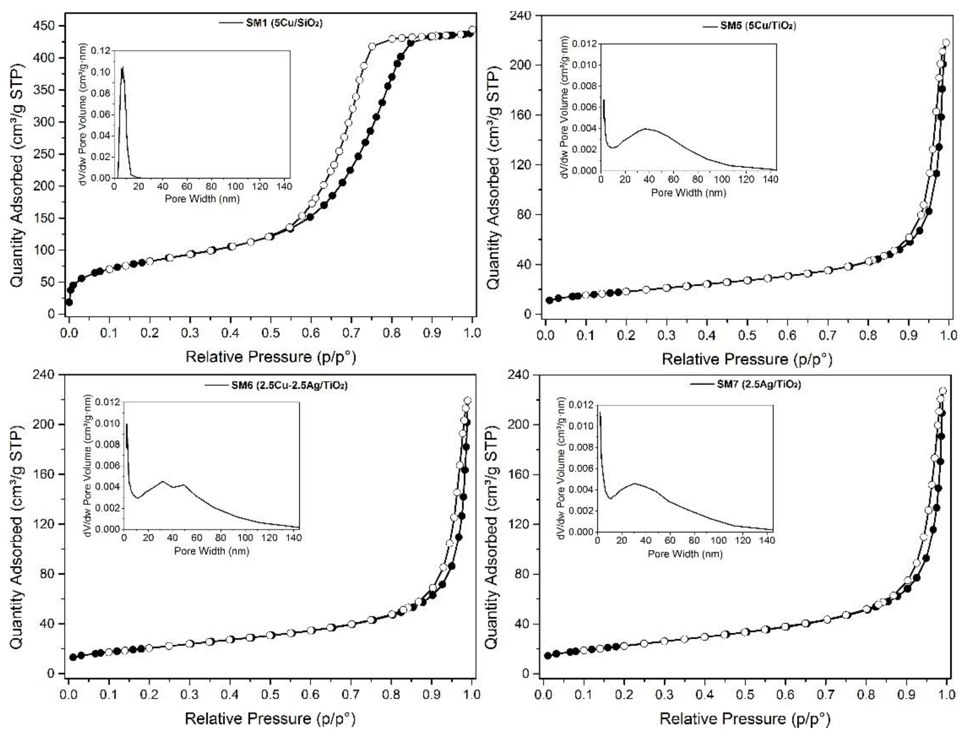
Table 2 show the isotherm profiles, pore size distribution, specific surface area (SA) and pore volume values. The isotherms are type IV, according to IUPAC classification, with hysteresis typical of mesoporous materials, especially for the silica-based ones.
5Cu/SiO2 (SM1) displays a specific surface area of 300 m2g-1, pore volume of 0.68 cm3g1, and a relatively narrow pore size distribution centered at 6.9 nm. Moreover, Cu, Ag, and Cu-Ag/TiO2 (SM5-7) exhibited lower (specific surface areas (45–48 m2g-1) and pore volume values around 0.47 cm3g-1.
The morphology of the antifouling fillers was studied by SEM pictures.
Figure 3 reports some SEM pictures of the SM1 sample. This material consists of large agglomerates (sizes between 40-100 mm) of nanoparticles (20-40 nm) of SiO
2 on the surface of which there are islands of agglomerates of large crystals (see figure 2-panel A) rich in copper as evidenced by EDX investigation. These crystals are probably constituted by copper oxide. Consequently, the composition of this material is very inhomogeneous, although the average content of Cu measured by the EDX resulted only slightly higher than the nominal value listed in
Table 1.
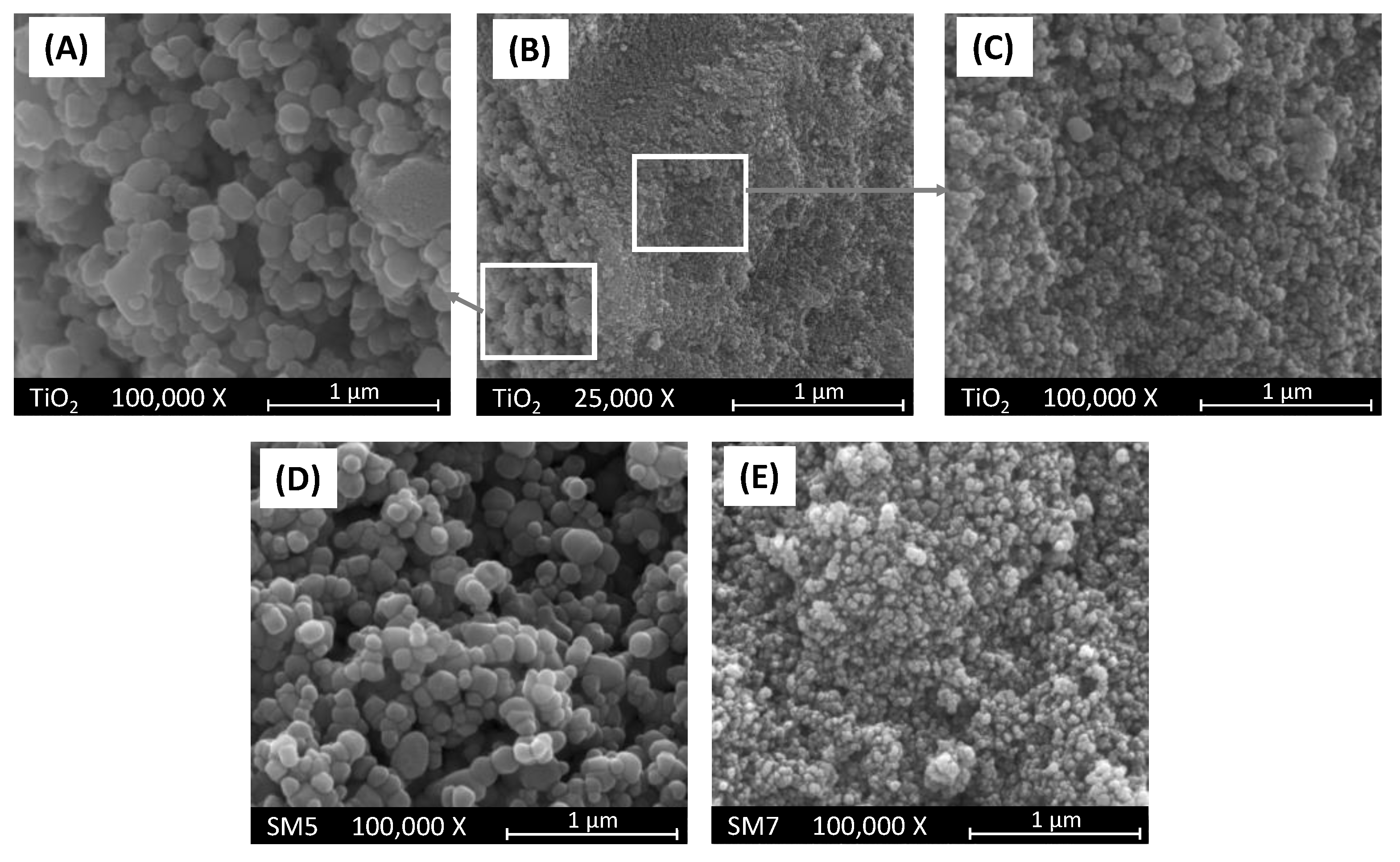
In panels (A), (B) and (C) of
Figure 4 are reported three pictures of the bare TiO
2 sample used as support of SM5 and SM7 materials which pictures are reported in the same
Figure 4 in panels (D) and (E), respectively. As it is possible to observe, the bare TiO
2 sample is constituted of agglomerates of nanoparticles with different sizes from ca. 20 to ca. 200 nm (see panels A and C). Interestingly, SM5 and SM7 samples obtained by loading TiO
2 with Cu and Ag, respectively, show the same morphology of bare TiO
2 as evidenced by the pictures reported in panels (D) and (E) of
Figure 4.
The EDX analysis indicates that, only in the case of SM7 sample, silver is uniformly deposited onto the surface of TiO
2, and its amount is practically equal to the nominal one. On the other hand, the distribution of copper onto the TiO
2 surface in the SM5 sample appears not uniform resulting, moreover, the average content of copper slightly higher with respect to the nominal value reported in
Table 1. As far as the SM6 sample is concerned, the SEM pictures not reported for the sake of brevity, indicate that the morphology of this material is also in this case very similar to that of the bare TiO
2 support but the distribution of Cu and Ag onto the TiO
2 surface is not uniform although their average content is very close to the nominal one (see
Table 1).
3.2. Evaluation of the adhesion power and rheological features of the coatings
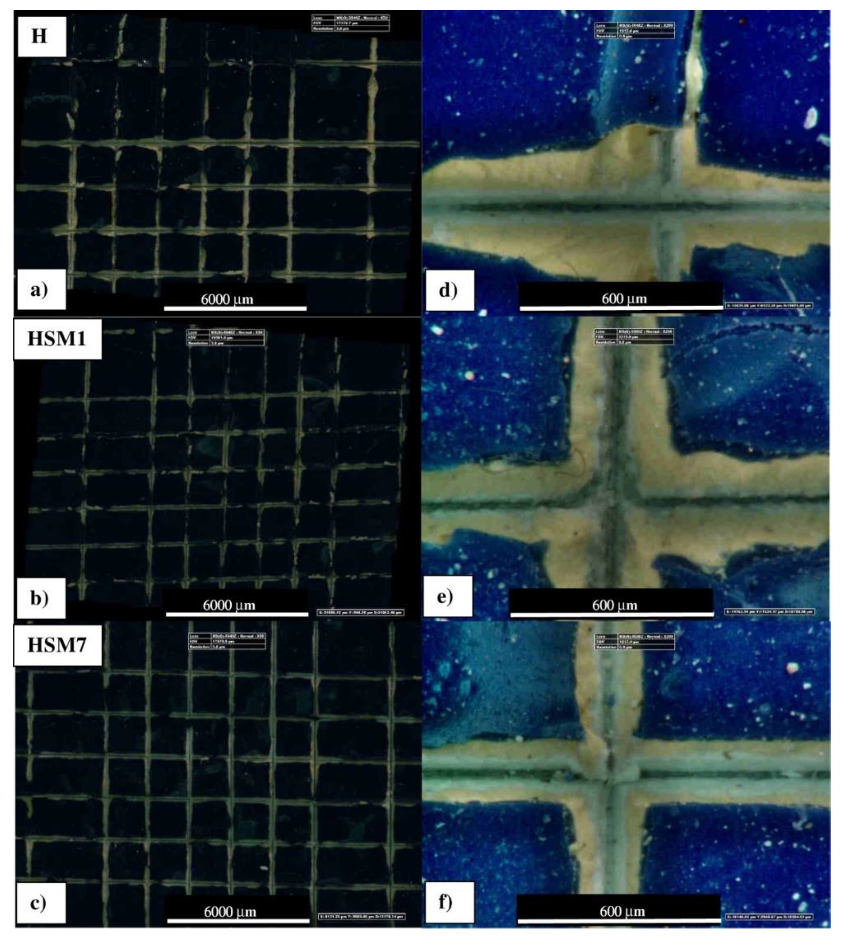
The evaluation of the adhesive properties of the coatings was carried out through two types of mechanical crosscut and pull-off tests. As we are going to see, both tests showed that the coatings we made in the laboratory (by mixing the antifouling fillers with the commercial silicone resin, H) gave an improvement in terms of adhesive properties. About the cross-cut test (shown in
Figure 5), we can see that the edges of the cuts are not completely flat because in some parts the squares of the lattice are detached. Commercial refence sample is close to HSM1 but it is different in adhesion compared to the HSM7 coating. After the incision of the cutting edge, large lateral portions around the points of passage of the blade are visibly detached in the commercial sample H (
Figure 5 a,d) . Likewise sample H, in sample HSM 1 portions of paint are detached along the edges, although to a slightly lesser extent (
Figure 5 b,e). The HSM7 specimen appears to have sharper cutting areas, with more limited portions of edge detachment than the other coatings discussed above (
Figure 5 c,f). However, this characterization technique does not allow for an accurate evaluation that a mechanical test such as the pull-off, discussed below, can give.
In accordance with the reference standards, all the samples had an adhesion evaluated as 3B (specifically for the ASTM D 3359-09e2) and ISO-2 (specifically for the ISO 2409:2007) [
29]. This uniquely high scratch resistance proves a satisfactory adhesion level of these coatings: we can define level 3B/2 as "sufficient" considering the ASTM/ISO scale from 1B/5 to 5B/0 in progressive terms of very poor, poor, sufficient, good, very good adhesion [
30].
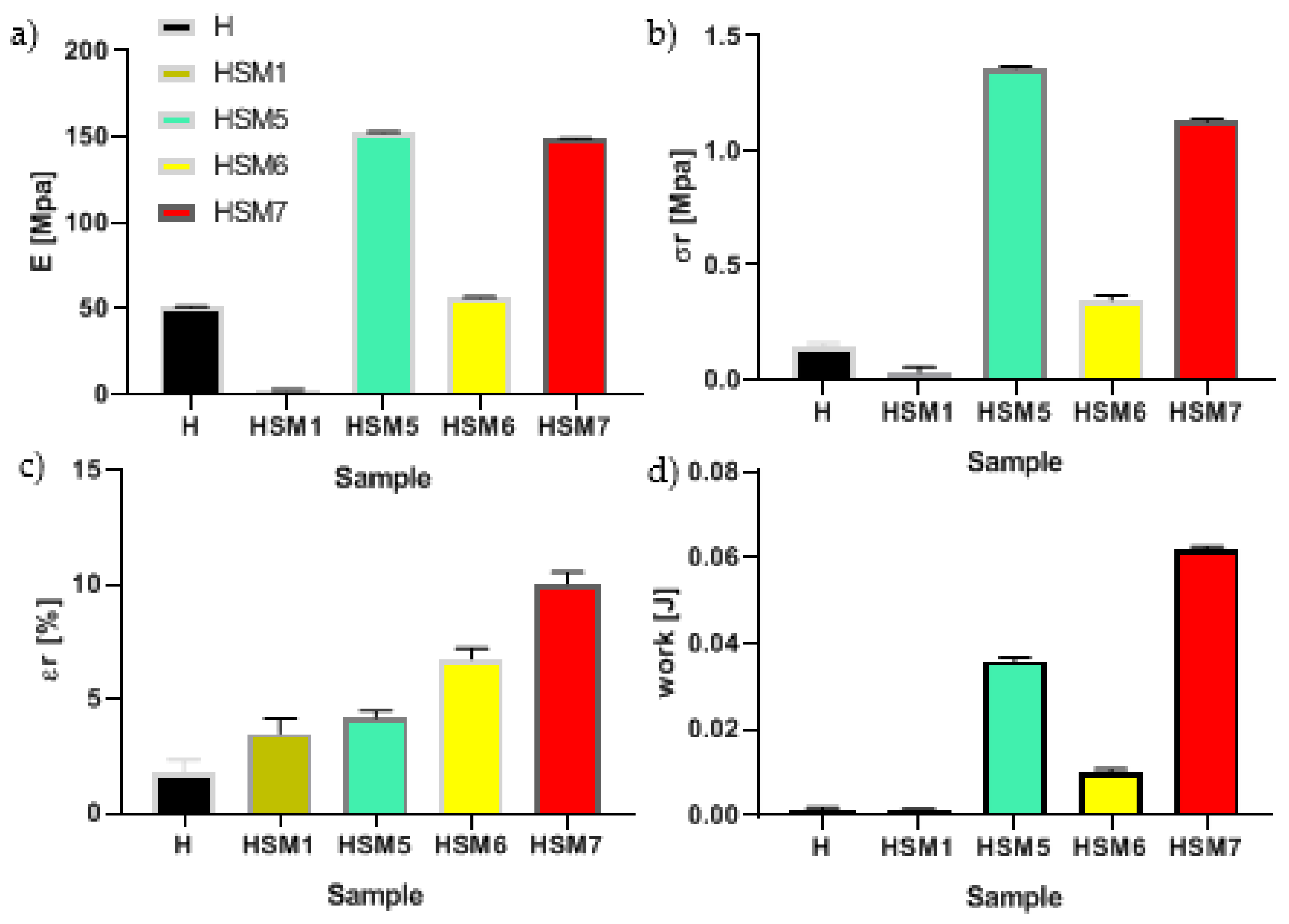
The pull off test result is resumed in
Figure 6. We can see that all the coatings based on titania (HSM5, HSM6, HSM7) exhibit better adhesion power that pure resin, H (p < 0.0001). In detail, the stiffness of pure resin is ~50 MPa, its tensile strength is ~0.15 MPa, the elongation at break is ~1.8% and the work at break is 1.3 10
-3 J. The HSM5 and HSM7 coating obtained the best values, especially in terms of strength (σ
r) and toughness (W
r), among all those analyzed (p < 0.0001). The HSM1 coating, which contains silica, on the other hand, gave the worst results in terms of adhesion. Its stiffness, mechanical strength and ductility are inferior to all coatings, including the commercial silicone one.
For this reason, our attention was focused on the HSM5 and HSM7 samples which showed quite similar properties to each other. In particular, the stiffness and mechanical strength and the modulus are ~1.3 MPa and ~150 MPa, respectively (p < 0.0001). The pull off strength of our eco-friendly coatings HSM5 and HSM7 is close to that of silane -based coatings with anticorrosive properties prepared by Arabpour at al., that is 1.25 ± 0.07 MPa [
2,
31].
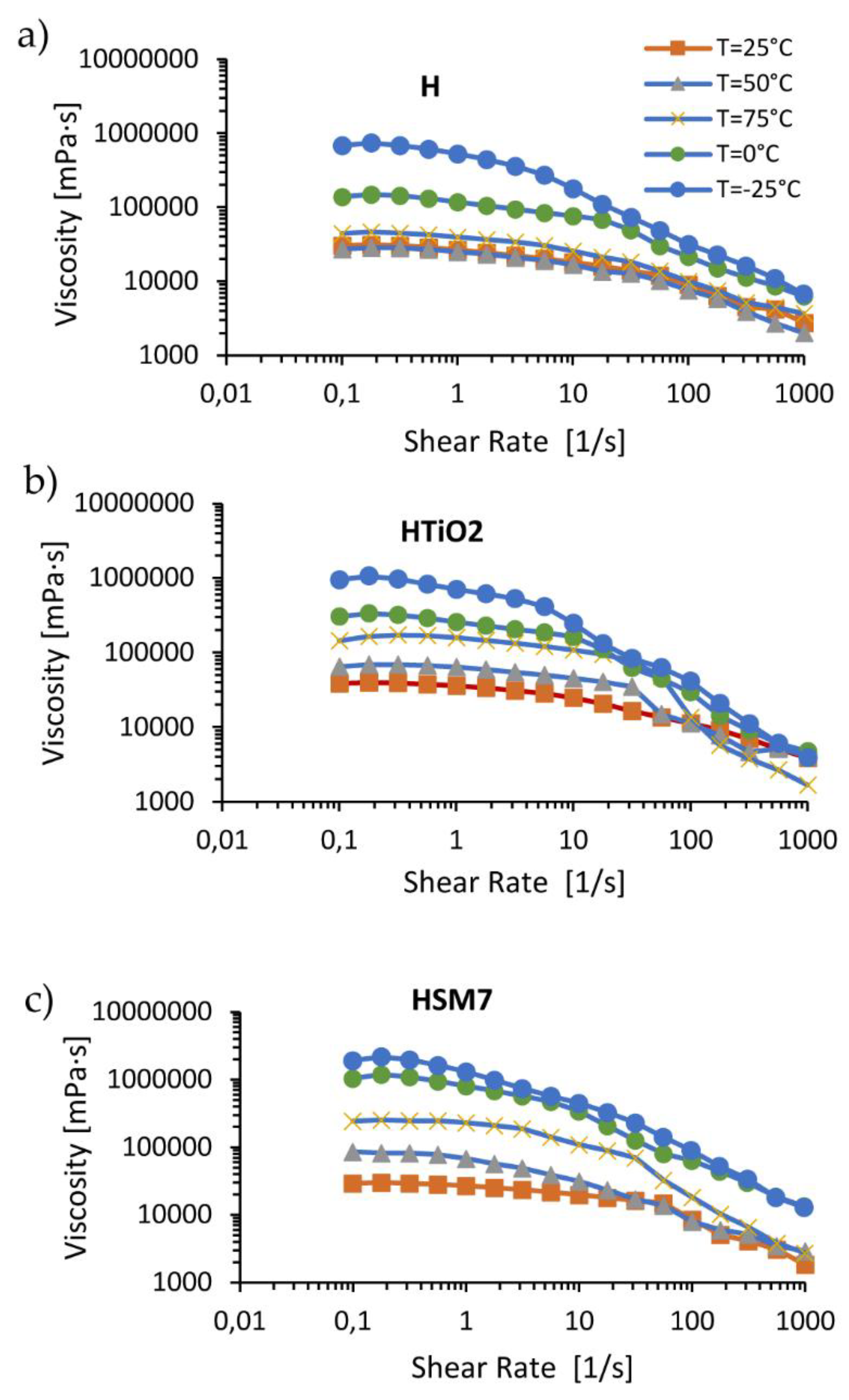
Since TiO2 is present in both the above-mentioned coatings, the subsequent in-depth rheological analyzes were carried out in pure resin (H), in H+TiO2 (or HTiO2), and in H+TiO2+Ag (HSM7). The aim was to understand if their adhesive power is linked to the presence of titania or to the presence of the metal deposited on titania (as in HSM7 sample).
In
Figure 7 we observe the flow curves as the temperature varies (range from -25 to +75 ° C). The flow curves relating to pure resin H, don’t vary much at temperatures in the range 25-50-75 ° C, remaining below 40,000 MPa*s. Instead, the temperature lowering to 0 ° C and to -25 ° C causes an increase in viscosity and the decrease in the extent of the curve at constant viscosity due to the ideal or Newtonian behavior, as expected.
The addition of titania, and of titania with metal (H+TiO2 and HMS7 samples, respectively), changes the rheological behavior of the coatings. The filler seems to act like a catalyzer of the chemical resin’s crosslinking reaction because the viscosity grows even more in the order: H < H+TiO
2 < H+TiO
2+Ag. This finding agrees with the TiO
2 ability in generating hydroxyl radicals that, reacting with the silicone resin molecules, catalyses the crosslinks between the resin chains [
32]. Moreover, metal species enhancing the photocatalytic activity of titania can enhance the crosslinking process [
33].
In
Table 3 the viscosity trend is numerically detailed: the viscosity of the coatings grows decreasing the temperature and vice versa, according to the Williams-Landel-Ferry or WLF-equation [
34]. This effect is quantitatively similar in all the coatings: the viscosity of pure H resin at -25°C (6.86 *10
5 mPa*sec) decreases up to 0.44 *10
5 mPa*sec at +75°C (93.6%). Similarly, the viscosity of HMS7 at -25°C (19.1 *10
5 mPa*sec) decreases up to 2.44 *10
5 mPa*sec at +75°C (-87.2%).
The addition of TiO
2 and even more the addition of TiO
2+Ag improves the coating’s viscosity. At the lowest temperature of -25°C, the viscosity of pure H coating grows from the value of 6.86 *10
5 mPa*sec, up to 19.1 *10
5 mPa*sec in H+TiO
2+Ag ( +178%). At the highest temperature of +75°C, the viscosity of pure H coating improves from the value of 0.44 *10
5 mPa*sec, up to 2.44 *10
5 mPa*sec in H+TiO
2+Ag (+454%). This notable raise in viscosity, despite the temperature being the highest of all those studied, ie 75 degrees centigrade, is justifiable considering the hypothesis that the presence of the filler can facilitate the cross-linking of the resin. It is in fact known that as the degree of crosslinking increases, the structural complexity of the macromolecule rises and therefore the difficulty of sliding of the coating increases, represented by a higher viscosity [
34].
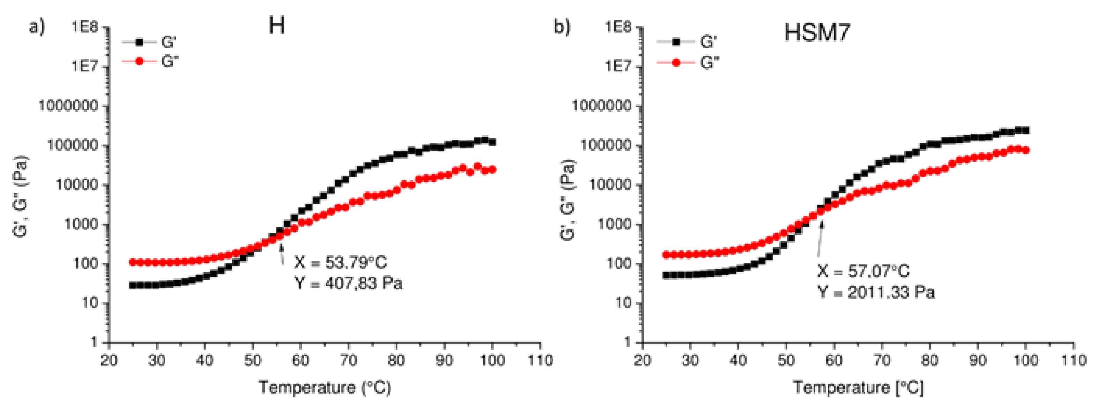
Finally, in
Figure 8 we observe the conservative modulus (G’) and of the viscosity modulus (G’’) as a function of temperature: their crossing point defines the crosslinking of the material. The cross-over point occurs at lower temperature in pure resin H than in HSM7 from 53.79 °C (
Figure 8a), to 57.07 °C (
Figure 8b). This confirms a higher degree of crosslinking in the HSM7 coating compared to the pure resin, as discussed above. The greater degree of cross-linking gives a better compactness and completeness to the coating with a consequent better adhesion to the substrate.
5. Conclusions
In the present work, we have focused on the application of selected "environmentally friendly" nanomaterials as antifouling fillers with different chemical composition, based on Cu and Ag on commercial silica and titania oxides to create new materials able to replace the currently existing antifouling commercially non-ecological paints.
The texture properties of the formulations were analyzed together with a SEM morphological investigation. The results suggested that the innovative antifouling powders act actively thanks to the nanometric size of the particles and the homogeneous dispersion of the metal on the substrate. However, the simultaneous presence of two metal species on the same support limits their dispersion at the nanometric level and therefore the formation of homogeneous compounds. The adhesion mechanical and rheological characterization tests indicated that the adhesion strength to the tie-coat layer improves compared to the pure resin after the addition of TiO2 and Ag. The presence of the antifouling filler facilitates the achievement of a higher degree of crosslinking of the pure resin, and therefore a better compactness and completeness of the coating. This leads to a consequent better degree of adhesion to the tie-coat and therefore to the steel support used for the construction of the boats.
Despite the potential of these oxides as antifouling materials, there is still a need for further research to optimize their properties and to better understand their mechanism of action against marine fouling organisms. Further research could also explore the potential of these oxides as part of a multi-component antifouling system, in combination with other materials and strategies, to optimize the optimal filler’s composition. To obtain this goal, more deep study about the biological long-term features is needed.
Author Contributions
Conceptualization, C.S., A.V. and L.F.L.; methodology, C.S., L.F.L.,C.C., G.M., and A.V.; validation, C.S., L.F.L., and A.V.; formal analysis, C.S., C.C., G.M., and A.V.; investigation, C.S., L.F.L.,C.C., G.M., and A.V.; data curation, C.S., L.F.L.,C.C., G.M., and A.V.; writing—original draft preparation, L.F.L., G.M., and A.V.; writing—review and editing, C.S., L.F.L., and A.V.; visualization, C.S., L.F.L.,C.C., G.M., and A.V.; supervision, L.F.L., and A.V.; project administration, L.F.L., and A.V.; funding acquisition, L.F.L., and A.V.; All authors have read and agreed to the published version of the manuscript.
Funding
This work was financially supported by the Project: “SI-MARE” (Soluzioni Innovative per Mezzi navali ad Alto Risparmio Energetico” PO FESR 201412020, n. 08ME7219090182, CUPG48I18001090007).
Data Availability Statement
The data presented in this study are available on request from the corresponding author.
Acknowledgments
This work was financially supported by the Project: “SI-MARE” (Soluzioni Innovative per Mezzi navali ad Alto Risparmio Energetico” PO FESR 201412020, n. 08ME7219090182, CUP G48I18001090007). C. Calabrese gratefully acknowledges the financial support of the Project “SI-MARE”.
Conflicts of Interest
The authors declare no conflict of interest.
References
- Callow, J.A.; Callow, M.E. Trends in the development of environmentally friendly fouling-resistant marine coatings. Nat. Commun. 2011, 2, 244. [Google Scholar] [CrossRef] [PubMed]
- Pistone, A.; Scolaro, C.; Visco, A. Mechanical properties of protective coatings against marine fouling: A review. Polymers 2021, 13, 173. [Google Scholar] [CrossRef]
- Nurioglu, A.G.; Esteves, A.C.C.; De With, G. Non-toxic, non-biocide-release antifouling coatings based on molecular structure design for marine applications. J. Mater. Chem. B 2015, 3, 6547–6570. [Google Scholar] [CrossRef] [PubMed]
- Pandit, S.; Sarode, S.; Sargunaraj, F.; Chandrasekhar, K. Bacterial-Mediated Biofouling: Fundamentals and Control Techniques. In Biotechnological Applications of Quorum Sensing Inhibitor; Kalia, V., Ed.; Springer: Singapore, 2018; pp. 263–284. [Google Scholar] [CrossRef]
- Baker, T.J.; Tyler, C.R.; Galloway, T.S. Impacts of metal and metal oxide nanoparticles on marine organisms. Environ. Pollut. 2014, 186, 257–271. [Google Scholar] [CrossRef] [PubMed]
- Champ, M.A. Economic and environmental impacts on ports and harbors from the convention to ban harmful marine anti-fouling systems. Mar. Pollut. Bull. 2003, 46, 935–940. [Google Scholar] [CrossRef] [PubMed]
- Jägerbrand, A.K.; Brutemark, A.; Barthel Svedén, J.; Gren, I.-M. A review on the environmental impacts of shipping on aquatic and nearshore ecosystems. Sci. Total Environ. 2019, 695, 133637. [Google Scholar] [CrossRef] [PubMed]
- Bellas, J. Comparative toxicity of alternative antifouling biocides on embryos and larvae of marine invertebrates. Sci. Total Environ. 2006, 367, 573–585. [Google Scholar] [CrossRef] [PubMed]
- Qian, P.Y.; Lau, S.C.K.; Dahms, H.U.; Lewin, R. Microbial adhesion is a sticky problem. Science 1984, 224, 375–378. [Google Scholar]
- Dobretsov, S.; Thomason, J.C. The development of marine biofilms on two commercial non-biocidal coatings: A comparison between silicone and fluoropolymer technologies. J. Bioadhesion Biofilm Res. 2011, 27, 869–880. [Google Scholar] [CrossRef]
- Sun, X.; Chen, R.; Gao, X.; Liu, Q.; Liu, J.; Zhang, H.; Yu, J.; Liu, P.; Takahashi, K.; Wang, J. Fabrication of epoxy modified polysiloxane with enhanced mechanical properties for marine antifouling application. Eur. Polym. J. 2019, 117, 77–85. [Google Scholar] [CrossRef]
- Hu, P.; Xie, Q.; Ma, C.; Zhang, G. Silicone-based fouling-release coatings for marine antifouling. Langmuir 2020, 36, 2170–2183. [Google Scholar] [CrossRef] [PubMed]
- Pistone, A.; Visco, A.M.; Galtieri, G.; Iannazzo, D.; Marino-Merlo, F.; Urzì, C.; De Leo, F. Polyester resin and carbon nanotubes based nanocomposite as new-generation coating to prevent biofilm formation. Int. J. Polym. Anal. Charact. 2016, 21, 327–336. [Google Scholar] [CrossRef]
- Yebra, D.M.; Kiil, S.; Dam-Johansen, K. Antifouling technology- past, present and future steps towards efficient and environmentally friendly antifouling coatings. Prog. Org. Coat. 2004, 50, 75–104. [Google Scholar] [CrossRef]
- IMO - International marine organization: BIOFOULING. Available online: https://www.imo.org/en/OurWork/Environment/Pages/Biofouling.aspx (accessed on 6 March 2023).
- Russell, G. Uc-Peraza, Ítalo B. Castro, Gilberto Fillmann, An absurd scenario in 2021: Banned TBT-based antifouling products still available on the market. Science of The Total Environment 2022, 805. [Google Scholar] [CrossRef]
- Iannazzo, D.; Pistone, A.; Visco, A.; Galtieri, G.; Giofre, S.; Romeo, R.; Romeo, G.; Cappello, S.; Bonsignore, M.; Denaro, R.; et al. 1,2,3-Triazole/MWCNT Conjugates as filler for gelcoat nanocomposites: New active antibiofouling coatings for marine application. Mater. Res. Express 2015, 2, 11. [Google Scholar] [CrossRef]
- Pistone, A.; Scolaro, C.; Celesti, C.; Visco, A. Study of Protective Layers Based on Crosslinked Glutaraldehyde/3-aminopropyltriethoxysilane. Polymers 2022, 14, 801. [Google Scholar] [CrossRef]
- Scurria, A.; Scolaro, C.; Sfameni, S.; Di Carlo, G.; Pagliaro, M.; Visco, A.; Ciriminna, R. Towards AquaSun practical utilization: Strong adhesion and lack of ecotoxicity of solar-driven antifouling sol-gel coating. Prog Org. Coat. 2022, 165, 106771. [Google Scholar] [CrossRef]
- Sfameni, S.; Rando, G.; Marchetta, A.; Scolaro, C.; Cappello, S.; Urzì, C.; Visco, A.; Plutino, M.R. Development of Eco-Friendly Hydrophobic and Fouling-Release Coatings for Blue-Growth Environmental Applications: Synthesis, Mechanical Characterization and Biological Activity. Gels 2022, 8, 528. [Google Scholar] [CrossRef]
- Sfameni, S.; Rando, G.; Galletta, M.; Ielo, I.; Brucale, M.; De Leo, F.; Cardiano, P.; Cappello, S.; Visco, A.; Trovato, V.; Urzì, C.; Plutino, M.R. Design and Development of Fluorinated and Biocide-Free Sol–Gel Based Hybrid Functional Coatings for Anti-Biofouling/Foul-Release Activity. Gels 2022, 8, 538. [Google Scholar] [CrossRef]
- Calabrese, C.; La Parola, V.; Cappello, S.; Visco, A.; Scolaro, C.; Liotta, L.F. Antifouling Systems Based on Copper and Silver Nanoparticles Supported on Silica, Titania, and Silica/Titania Mixed Oxides. Nanomaterials 2022, 12, 2371. [Google Scholar] [CrossRef]
- Pascariu, P.; Cojocaru, C.; Samoila, P.; Airinei, A.; Olaru, N.; Rotaru, A.; Romanitan, C.; Tudoran, L.B; Suche, M. , Cu/TiO2 composite nanofibers with improved photocatalytic performance under UV and UV–visible light irradiation. Surfaces and Interfaces 2022, 28, 101644. [Google Scholar] [CrossRef]
- Zhou, J.L.; Shi, D.C.; Jia, C.C. Robust nanoporous Cu/TiO2 ceramic filter membrane with promoted bactericidal function. Sci. China Technol. Sci. 2022, 65, 2687–2694. [Google Scholar] [CrossRef]
- Ruffolo, S.A; Macchia, A.; La Russa,M. F.; Mazza, L.; Urzì, C.: De Leo,F.; Barberio, M.; Crisci, G.M., Marine Antifouling for Underwater Archaeological Sites: TiO2 and Ag-Doped TiO2. Hindawi Publishing Corporation, International Journal of Photoenergy 2013, 23, 6. [Google Scholar] [CrossRef]
- Guo, X.; Pan, G.; Fang, L.; Liu,Y. ; Rui, Z., Z-Scheme CuOx/Ag/TiO2 Heterojunction as Promising Photoinduced Anticorrosion and Antifouling Integrated Coating in Seawater. Molecules 2023, 28, 456. [Google Scholar] [CrossRef]
- Calabrese, C.; La Parola, V.; Testa, M.L.; Liotta, L.F. Antifouling and antimicrobial activity of Ag, Cu and Fe nanoparticles supported on silica and titania. Inorg. Chim. Acta 2022, 529, 120636. [Google Scholar] [CrossRef]
- Hempel’s Silic One. Available online: https://www.hempel.com/products/hempels-silic-one-77450 (accessed on 11 June 2022).
- ASTM D3359-09e2, Standard Test Methods for Measuring Adhesion by Tape Test. Available online: https://www.astm.org/d3359-09e02.html (accessed on 6 March 2023).
- ISO 2409:2007, Paints and varnishes — Cross-cut test. Available online: https://www.iso.org/standard/37487.html (accessed on 6 March 2023).
- Arabpour, A.; Shockravi, A.; Rezania, H.; Farahati, R. Investigation of anticorrosive properties of novel silane-functionalized polyamide/GO nanocomposite as steel coatings. Surf. Interfaces 2020, 18, 100453. [Google Scholar] [CrossRef]
- He, X.; Wu, M.; Ao, Z.; Lai, B.; Zhou, Y.; An, T.; Wang, S. ; Metal–organic frameworks derived C/TiO2 for visible light photocatalysis: Simple synthesis and contribution of carbon species. Journal of Hazardous Materials 2021, 403, 124048. [Google Scholar] [CrossRef]
- Kim, J.K.; Metcalfe, I.S. ; Investigation of the generation of hydroxyl radicals and their oxidative role in the presence of heterogeneous copper catalysts. Chemosphere 2007 69, 689–696. [CrossRef]
- Bruckner, S. ; Allegra,G.; Pegoraro, M.; La Mantia F.P.; Scienza e tecnologia dei materiali polimerici, Edises Ed., Napoli, Italy, 2020. 8879. [Google Scholar]
Figure 1.
scheme of layers deposited on the DH36 steel (a); image of the painted steel samples for the mechanical adhesion tests (b); image of the experimental set-up for the pull-off test (c).
Figure 1.
scheme of layers deposited on the DH36 steel (a); image of the painted steel samples for the mechanical adhesion tests (b); image of the experimental set-up for the pull-off test (c).
Figure 2.
N2-adsorption/desorption isotherms of SM1, SM5, SM6 and SM7. Pore size distribution (inset).
Figure 2.
N2-adsorption/desorption isotherms of SM1, SM5, SM6 and SM7. Pore size distribution (inset).
Figure 3.
SEM pictures of SM1 sample at two different magnifications. Pictures (A) and (C) report enlargements of the two areas evidenced in picture (B).
Figure 3.
SEM pictures of SM1 sample at two different magnifications. Pictures (A) and (C) report enlargements of the two areas evidenced in picture (B).
Figure 4.
SEM pictures of (A–C) bare TiO2 at two different magnifications, (D) SM5 and (C) SM7 samples. Pictures (A) and (C) report enlargements of the two areas evidenced in picture (B).
Figure 4.
SEM pictures of (A–C) bare TiO2 at two different magnifications, (D) SM5 and (C) SM7 samples. Pictures (A) and (C) report enlargements of the two areas evidenced in picture (B).
Figure 5.
Optical microscope images of the adhesion cross-cut test of commercial topcoat H, HSM1 and HSM7 with 50x magnification (a,b,c, respectively), 200× (d,e,f respectively).
Figure 5.
Optical microscope images of the adhesion cross-cut test of commercial topcoat H, HSM1 and HSM7 with 50x magnification (a,b,c, respectively), 200× (d,e,f respectively).
Figure 6.
Mechanical parameters of pull-off test of commercial tie coat H and of HSM(x) topcoats: Young’s modulus E (a), the stress at break, σr (b); the deformation at break, εr (c) and the work at break, Wr (d).
Figure 6.
Mechanical parameters of pull-off test of commercial tie coat H and of HSM(x) topcoats: Young’s modulus E (a), the stress at break, σr (b); the deformation at break, εr (c) and the work at break, Wr (d).
Figure 7.
Flow curves (left column) and loss/conservative modulus at different temperatures (right column) of H (a), HTiO2 (b) and HSM7(c).
Figure 7.
Flow curves (left column) and loss/conservative modulus at different temperatures (right column) of H (a), HTiO2 (b) and HSM7(c).
Figure 8.
Conservative (G’) and loss modulus (G’’) at different temperatures of pure resin, H (a), and of H+TiO2+Ag (HSM7) (b).
Figure 8.
Conservative (G’) and loss modulus (G’’) at different temperatures of pure resin, H (a), and of H+TiO2+Ag (HSM7) (b).
Table 1.
Label and chemical composition (nominal and actual) of the prepared fillers.
Table 1.
Label and chemical composition (nominal and actual) of the prepared fillers.
| . |
Chemical composition |
| Sample (code) |
Nominal
(wt%) |
Nominal
(at%) |
*Actual
(at%) |
| Cu/SiO2 (SM1) |
Cu (5.0) |
4.7 |
6.4 |
| Cu/TiO2 (SM5) |
Cu (5.0) |
6.2 |
10 |
| Cu-Ag/TiO2 (SM6) |
Cu (2.5)-Ag (2.5) |
Cu (3.1)-Ag (1.9) |
Cu (3.6)-Ag (1.6) |
| Ag/TiO2 (SM7) |
Ag (2.5) |
1.9 |
1.9 |
Table 2.
Textural properties of samples from N2-adsorption/desorption data.
Table 2.
Textural properties of samples from N2-adsorption/desorption data.
| Sample (code) |
SABet
|
Pore Volume
(BJH method)
|
Pore width
(BJH method)
|
| |
m2/g |
cm3/g |
nm |
| Cu/SiO2 (SM1) |
300 |
0.68 |
6.9 |
| Cu/TiO2 (SM5) |
45 |
0.45 |
35 |
| Cu-Ag/TiO2 (SM6) |
46 |
0.47 |
40 |
| Ag/TiO2 (SM7) |
47 |
0.48 |
35 |
Table 3.
Viscosity of the reference resin H at different temperatures before and after the addition of fillers at 1 wt% (TiO2 and TiO2+Ag) at shear rate of 1 sec-1.
Table 3.
Viscosity of the reference resin H at different temperatures before and after the addition of fillers at 1 wt% (TiO2 and TiO2+Ag) at shear rate of 1 sec-1.
| Sample |
→ |
H+TIO2
|
H+TiO2+Ag (HSM7) |
| T (°C) |
η (mPa.sec) E+05
|
| -25 |
6.86 |
9.42 |
19.1 |
| 0 |
1.38 |
3.05 |
10.4 |
| 25 |
0.30 |
0.38 |
0.39 |
| 50 |
0.27 |
0.65 |
0.86 |
| 75 |
0.44 |
1.44 |
2.44 |
|
Disclaimer/Publisher’s Note: The statements, opinions and data contained in all publications are solely those of the individual author(s) and contributor(s) and not of MDPI and/or the editor(s). MDPI and/or the editor(s) disclaim responsibility for any injury to people or property resulting from any ideas, methods, instructions or products referred to in the content. |
© 2023 by the authors. Licensee MDPI, Basel, Switzerland. This article is an open access article distributed under the terms and conditions of the Creative Commons Attribution (CC BY) license (https://creativecommons.org/licenses/by/4.0/).

