1. Introduction
45 steel shaft parts are extensively utilized in the military, aerospace, power, and shipbuilding sectors because of their ability to load bearing and transfer torque while machinery is in operation. High-speed rotation, extreme friction, and prolonged corrosion make these components fragile and prone to failure [
1,
2]. Consequently, the service life of components may be effectively increased by producing wear-resistant and corrosion-resistant coatings on the surfaces of parts during production. There is great potential for extreme high-speed laser cladding technology to displace hard chromium plating and green manufacturing due to its high cladding efficiency, high powder utilization rate, small heat-affected zone, low dilution rate, and pollution-free manufacturing process [
3,
4,
5]. Powder particles are melted above the melt pool by optimizing the coupling of process parameters, causing the substrate and cladding materials to combine and solidify in the molten state, resulting in a metallurgical bond coating, and thereby preparing high-performance coatings in a cost-effective and time-efficient manner [
6,
7]. However, due to the late start of extreme high-speed laser cladding technology, the research is still in the exploration stage of process parameters, improving coating performance, and promoting technology, and it relies primarily on experimental experience and the trial-and-error method to optimize the process parameters and improve the coating quality [
8,
9,
10]. By combining simulation and experimentation, the time needed to perfect the laser cladding coating technique can be reduced [
11].
Progress has been achieved in the study of the numerical simulation and technology of ultra-high-speed laser cladding by researchers both at home and abroad. Experimental comparisons of the organizational performance of conventional laser cladding and ultra-high-speed laser cladding conducted by Li et al. [
12] revealed that the latter had a finer and more uniform coating organization. Comparative experiments conducted by Wang et al. [
13] on conventional laser cladding and ultra-high speed laser cladding of iron-based amorphous coatings revealed that the latter have superior performance thanks to their fine microstructure and hardness of more than 1300 HV in terms of wear and corrosion resistance. Preparing an ultra-high-speed laser-clad M2 alloy coatings, Zheng et al. [
14] investigated the influence of process parameters on the creation of the clad layer and characterized the coating in terms of its shape, microhardness, and wear resistance. The impact of powder particle size and bonding rate on coating quality was investigated by Lou et al. [
15], who looked at the morphology of the coating's organization when applied using low-power ultra-high-speed laser cladding. To better understand why laser melting speeds affect mechanical properties, Ding et al. [
16] compared the microstructure of Inconel 625 coatings produced using ultra-high speed laser melting and conventional laser melting. They found that increasing the laser melting speed and converting coarse columnar crystals into fine dendrites improved the coatings' hardness, wear resistance, and corrosion resistance. Li et al. [
17,
18] established a combined heat source model based on the finite element method, studied the temperature distribution of the ultra-high-speed laser-clad AISI 4140 melt pool, and used this model to investigate the impact of laser power and cladding speed on the resulting temperature field and stress field. In conclusion, there has been a great deal of study on the process optimization and coating quality assessment of ultra-high-speed laser cladding, but only a smattering of studies on the temperature development law and residual stress of coating under such conditions.
This work established a finite element model of laser single-track fusing thermal coupling at extreme high speed and utilized that model to investigate the impact of changing process parameters on the cathodic protection of 431 stainless steel. After determining the ideal process parameters, numerical calculation and temperature field verification are carried out. Future research into coatings cracking and the optimization of the extreme high-speed laser fusing process can be built on the solid foundation laid out in this paper, which predicts the residuals of the fused coating and examines the impact of temperature gradient and cooling rate on the coatings' microstructure during the process.
2. Materials and Methods
In this experiment, 45 steel was employed as the base material with a φ40 mm steel shaft, and 431 stainless steel powder with a particle size of 50–150 μm was used as the cladding material. The chemical compositions of the cladding powder and the base material are listed in
Table 1.
Extreme high-speed laser cladding experiments were performed utilizing the entire suite of machinery from China Machinery Institute of Advanced Materials Co., Ltd. The laser beam spot diameter was 1 mm, and the highest power was 3300 W, with the powder being fed in a coaxial fashion. Extreme high speed laser cladding's single-channel forming size was primarily considered by analyzing the effects of laser power, cladding speed, and powder feeding speed using the single-factor experiment method, which took into account previous process experiments, theoretical research, and industrial application practice. Parameters used in the experiment are listed in
Table 2. When doing a numerical simulation computation, the optimal process experiment technique is employed to choose which parameters to use.
In order to acquire a metallographic sample that is perpendicular to the cladding speed direction, a sample was taken from the cladding layer and processed using line cutting. The sample was then implanted, polished, and corroded in 4% ethanol and FeCl
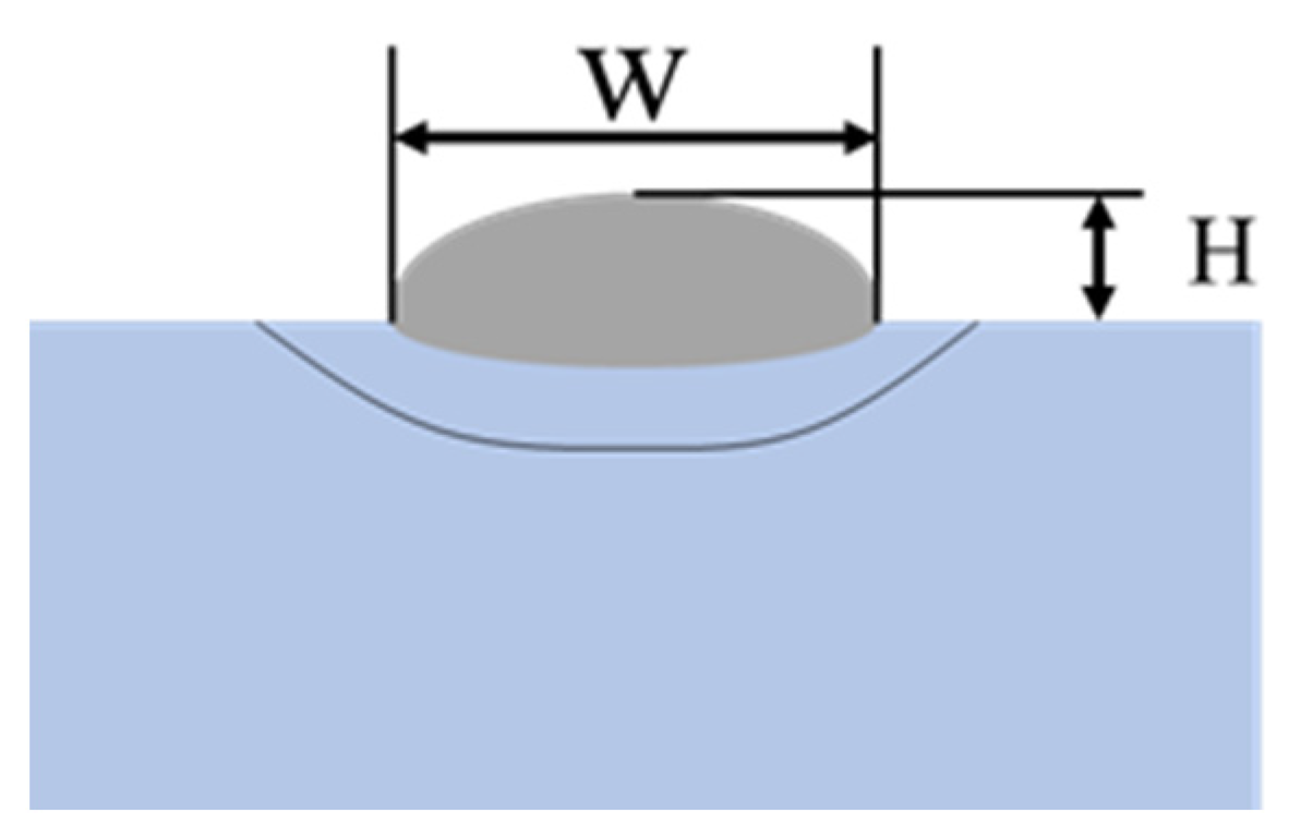
3+HCl aqueous solutions, respectively. Using an optical microscope, we studied the morphology of the microstructure and determined the width W and height H of the single-track coating cross-section, as shown in
Figure 1.
3. Finite element simulation
3.1. The control equation and boundary conditions
Extreme high-speed laser cladding is a rapid-heating and rapid-cooling technique that involves intricate heat and mass transport processes. Because heat conduction occurs mostly inside a material and because material properties vary greatly with temperature, the heat transfer process is very nonlinear, and its control equation is [
19,
20]:
where ρ is the material density; c is the material's specific heat; T is the temperature; t is the heat transfer time; λ is the material's thermal conductivity; and Q is the internal heat source, including phase change latent heat and heat source load's heat generation, where ρ, c, and λ are all functions of temperature.
In the laser cladding process, thermal radiation and thermal convection are the main heat transfer boundary conditions, and the boundary condition equation is as follows [
18,
19]:
where λ is the material thermal conductivity; T is the temperature; T
0 is the initial ambient temperature; h is the convection heat transfer coefficient; T
s is the material surface temperature; σ is the Stefan-Boltzmann constant; ε is the material surface radiation coefficient; and A is the material surface absorption coefficient for laser energy.
3.2. Heat source model
Laser cladding involves melting material above the substrate with a high-energy laser beam, and then applying some of that energy to the substrate to create a metallurgical bond layer. Accuracy of findings from numerical simulations is heavily influenced by the energy distribution. Since the laser energy distribution features in the cladding process include both a high-order Gaussian distribution and a variable-density distribution, a combined heat source model is employed for modeling. The powder material is subjected mostly to the high-order Gaussian energy distribution, whereas the substrate material is subjected primarily to the variable-density heat source model [
20,
21]. Energy is distributed according to a high-order Gaussian as seen below:
where P is the laser power; η is the utilization efficiency of the laser energy;
ξ1 is the proportion of energy allocated to the high-order Gaussian heat source, which is 0.8; r is the distance from the center of the laser beam; R is the radius of the laser beam; and n is the order of the heat source.
A variable-density heat source is used to simulate the heating of the substrate, and the energy distribution is as follows [
21]:
where P is the laser power; η is the utilization rate of laser energy; ξ
2 is the energy ratio allocated to the variable-density heat source, taken as 0.2; R is the distance from the center of the laser beam; r is the radius of the laser beam; a1 is an empirical parameter, taken as 1.6; and h
0 is the depth of laser heating on the substrate.
3.3 Finite Element Model
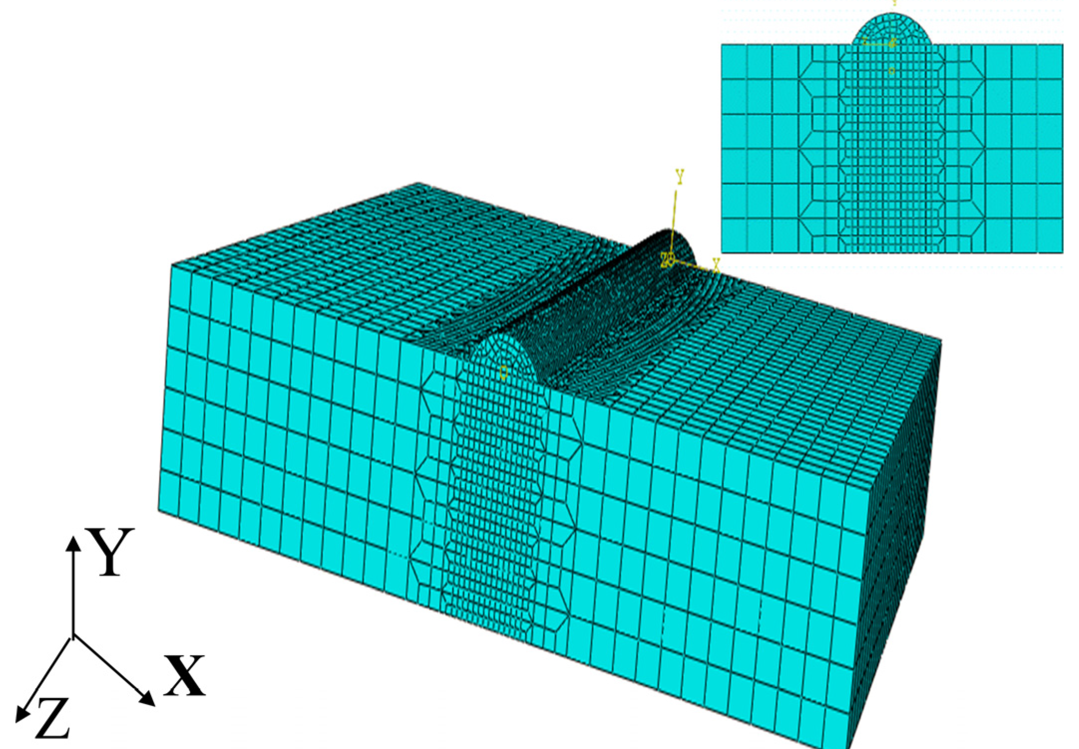
Abaqus software was used to create a geometric model based on the actual procedure of 431 stainless steel coating on the surface of 45 steel shaft parts; the finite element model and mesh division are displayed in
Figure 1; the substrate was sized at 10 mm×10 mm× 3 mm, and the coatings had height and width parameters of 0.2 mm and 1 mm, respectively. The mesh was fine-tuned close to the coating layer, with a minimum mesh size of 0.05 mm, and coarsened further from the coating layer, with a maximum mesh size of 0.3 mm, to improve computation accuracy and efficiency. Grids were numbered 59760, and nodes added up to 252367 in total. First, the temperature field was calculated, then the node temperature was used as a load in a stress field calculation, and finally, the residual stress distribution was obtained through a numerical calculation simulation process that used a sequentially coupled method. After a DC3D8 linear heat conduction tetrahedral element was utilized to calculate the temperature field, a C3D8R linear hexahedral element was employed to analyze the stress field. Living and dead element technology was used in the model, and the coatings were already in place. Coaxial powder feeding characteristics were more accurately simulated by progressively adding the coating to the heating calculation model as the heat source was shifted. To accomplish the goal of simultaneous material addition and heat source loading, the Fortran language is used to create a subroutine for the heat source, and the "Model Change" is used to put the subroutine into action.
Figure 2.
Finite element model and mesh division.
Figure 2.
Finite element model and mesh division.
3.4. Material Parameter Model
Parameters like density, specific heat, thermal conductivity, Poisson's ratio, Young's modulus, yield strength, etc. are essential to analyzing the thermal coupling of ultra-high-speed laser cladding. Calculations and interpolation using the JmatPro calculation program, based on the material composition in
Table 1, may provide the high-temperature physical properties of the material.
Table 3 and
Table 4 display the obtained data.
4. Results and Discussion
4.1 The Influence of Process Parameters on the Macro-shape of the Coating Layer
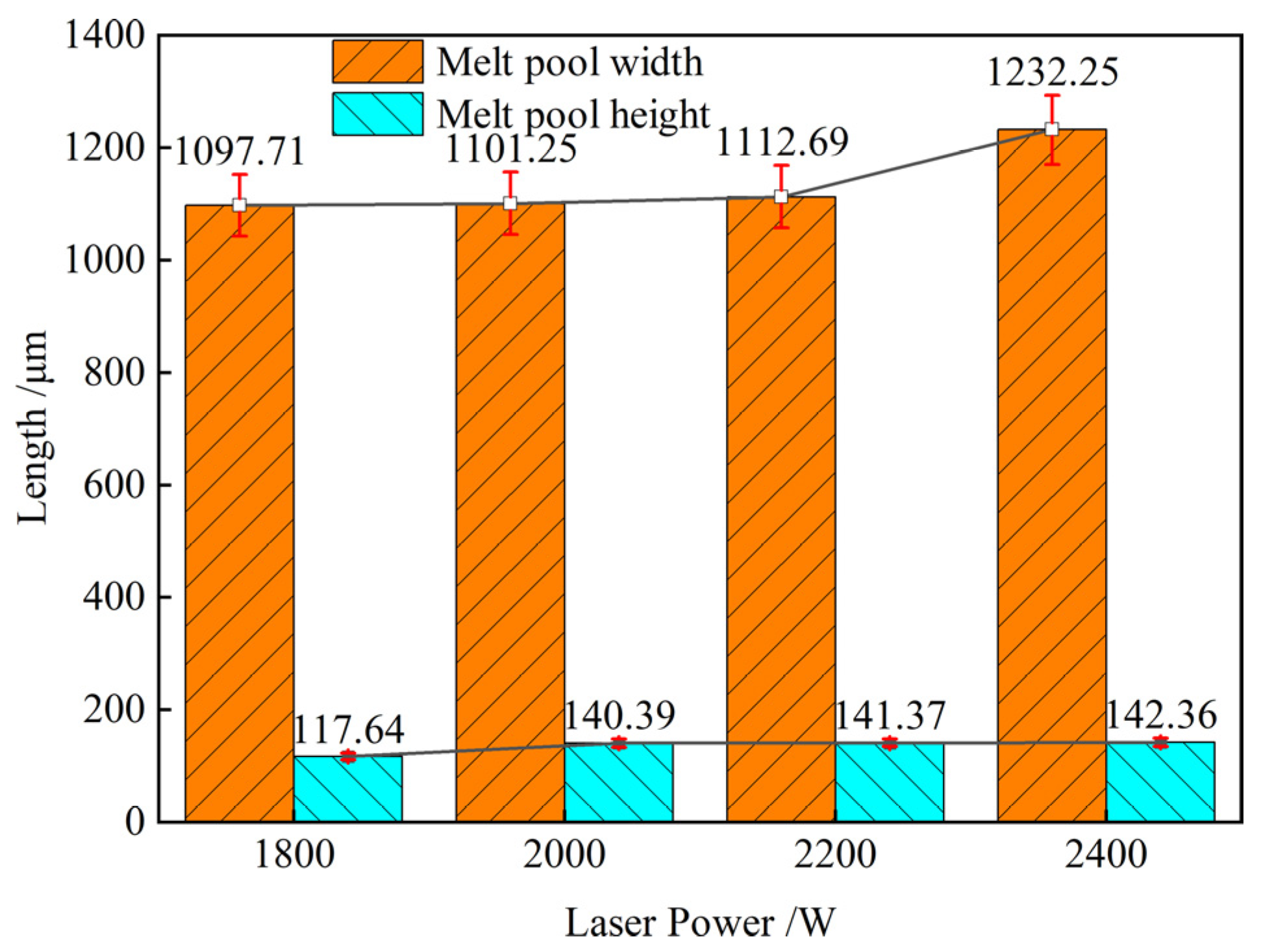
Figure 3 shows how laser power from 1800 to 2400 W affected coating section size at 20 m/min melting and 20.32 g/min powder feeding.
Figure 3 indicates that laser power increased coating section width and height. Laser power increased from 1800 to 2400 W, making the coating 12.3% wider and 21.0% higher. Even when the powder feeding rate and melting rate stay unchanged, the melt pool becomes wider and higher as the laser power increases, the laser energy density rises, and more materials are melted. The curve's basic form shows that the melt pool's height and width react more strongly to laser power at low and high laser powers, respectively. Thus, the width and height of the melt pool grow with laser intensity, with the latter being more evident.
The coating single-channel cross-sectional size and melting rate were investigated in the research shown in
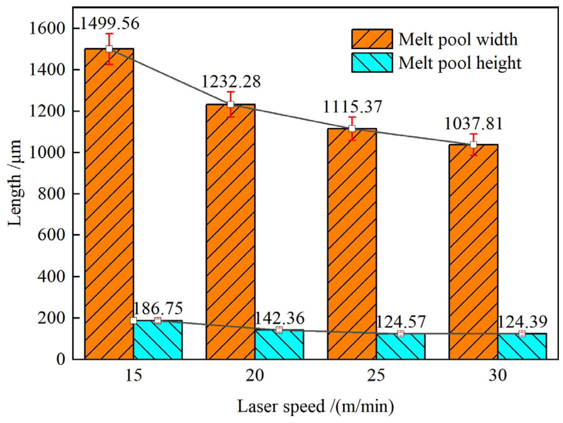
Figure 4; the powder feeding rate was held unchanged at 20.32 g/min, and the laser power was set at 2400 W.
Figure 4 shows that when the melting rate was raised from 15 to 30 m/min, both the width and height of the coating dropped. The reduction in width was 33.4%, and the fall in height was 30.8%. Powder particles and substrates spend less time under the laser's irradiation when the melting rate is increased, resulting in less energy being absorbed per unit time of the material, less material being melted, and the molten pool becoming unstable, resulting in a reduction in breadth and height. When both the powder feeding rate and the laser power are held constant, this holds true. As the trend changes, it becomes clear that the melting rate is increasing, which might result in a significant reduction in the cross section's width and height.
As can be seen in
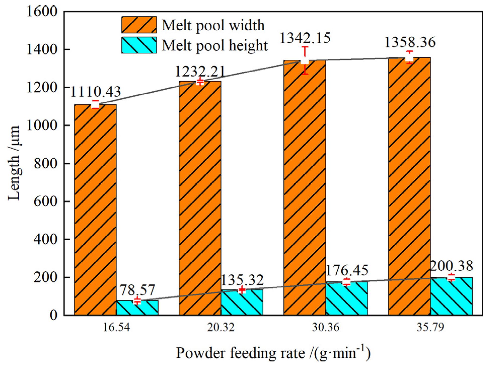
Figure 5, the effect of powder feed rate on coating section size was investigated while maintaining a constant laser power of 2400 W and fusion rate of 20 m/min.
Figure 5 demonstrates that the fusion layer grows in both height and breadth when the powder feed rate is increased. When the powder feed rate was raised from 16.54 g/min to 35.79 g/min, the coating grew in breadth by 22.34% and in height by 155.03%. Increases in powder feed rate result in more powder being melted in the same amount of time, but this results in less energy being absorbed by the substrate, a cooler molten pool, and weaker bonds.
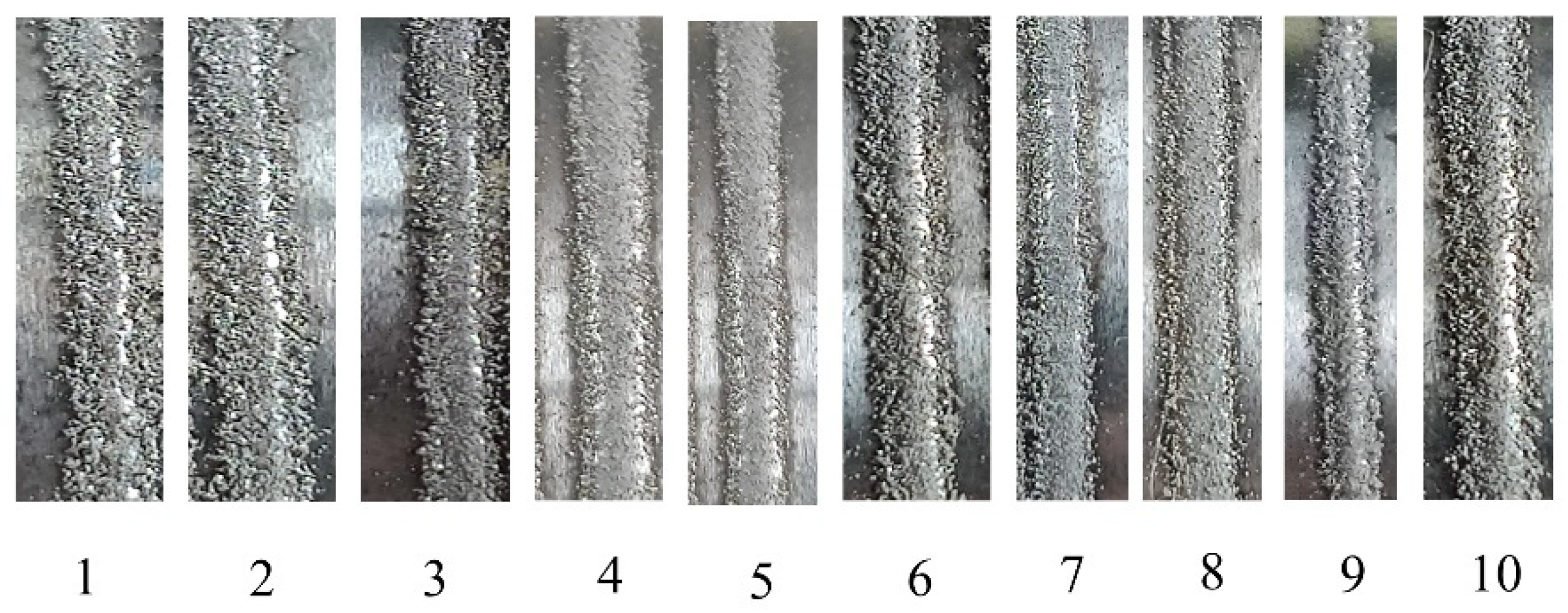
Figure 6 shows the unpolished surface of the molten coatings, which was observed during temperature and stress field investigations to establish ideal processing parameters. If you look at
Figure 6, you'll see that samples No. 1 and No. 2 have a lot of unmelted powder particles at the coating's edge due to weak laser power, and the stable melt pool is not formed; samples No. 3 can form a temperature melt pool, but the coating sticky powder phenomenon is serious; samples No. 4 and No. 5 have a good surface condition; samples No. 6, No. 7, and No. 8 can form a temperature melt pool, but the sticky powder phenomenon is serious; and many others. After considering surface condition analysis, melting rate, laser power, and melting section size, Sample No. 4's process parameters were selected for a numerical simulation study.
4.2. Temperature Field Numerical Simulation and Verification
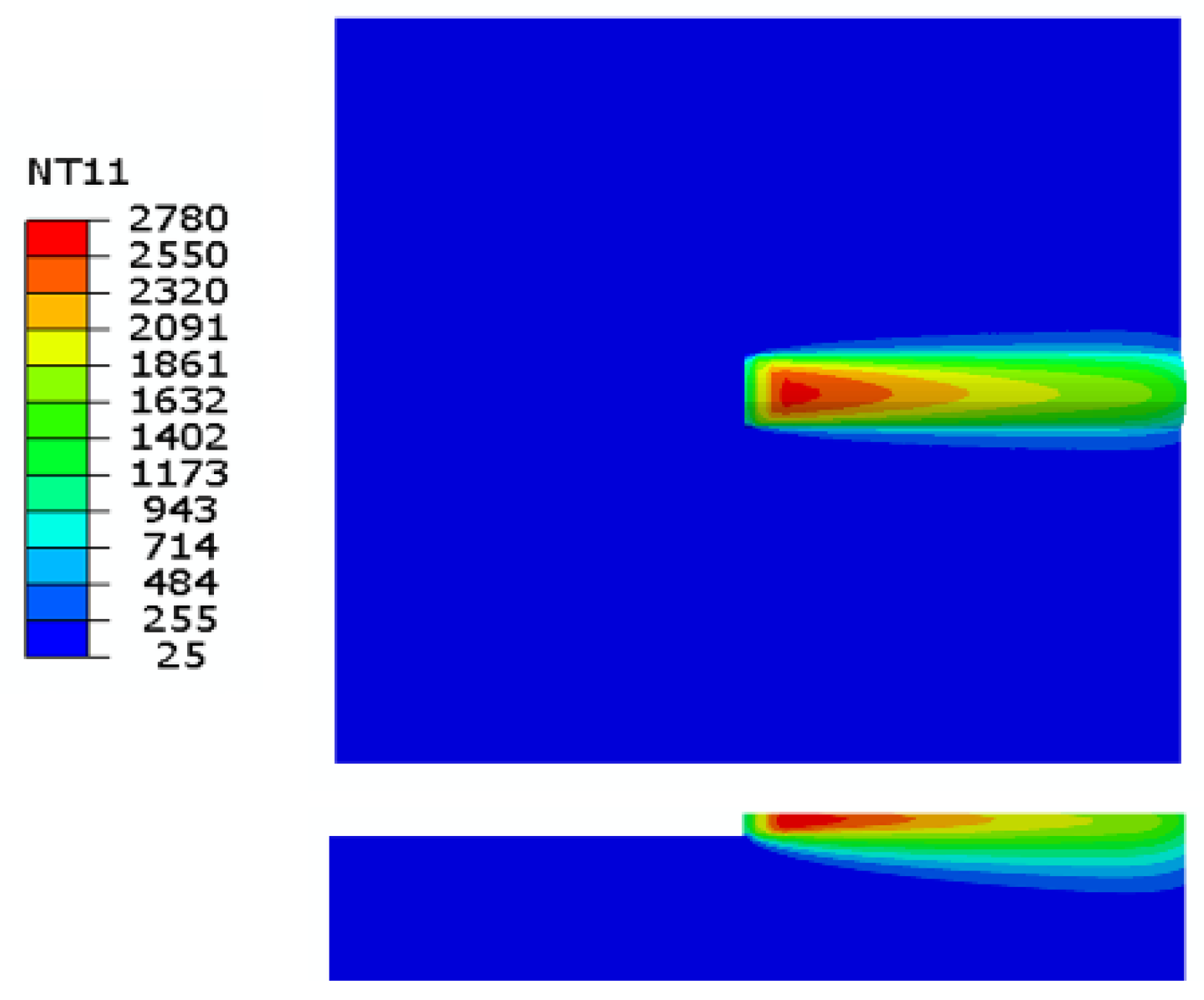
The melting time was 0.03 s, and the other process was cooling. Based on the findings of the process experiment, the parameter of sample No. 4 was chosen as the numerical simulation parameter, with a total calculation time of 600 s. The temperature field distribution was halted for analysis at t = 0.015 s to produce a more uniform molten pool dispersion.
Figure 7 depicts the temperature distribution in progress during ultra-fast laser melting. The maximum melting temperature was 2780 °C, with a tiny heat-affected zone forming where the molten layer bonded to the substrate at temperatures close to its melting point. A long molten pool was created as a consequence of the high melting rate, with a big temperature gradient in the front half of the pool and a tiny temperature gradient in the back, giving the pool an oval shape.
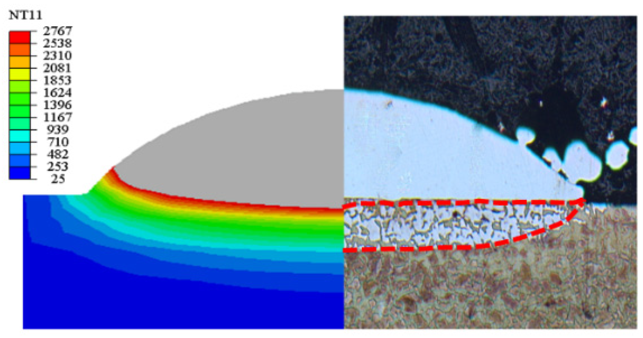
Figure 8 shows a comparison between the transverse section of an experimental molten layer and the numerical simulation molten pool section. The results show that the size of the numerical simulation molten pool is in good agreement with the actual melting size, that the heat-affected zone is in good agreement with the numerical simulation results, that the dilution rate is low, and that the statistical error is less than 6.42%.
4.3. The influence of cooling rate and temperature gradient on coating structure
To study melting and solidification heat transfer processes,
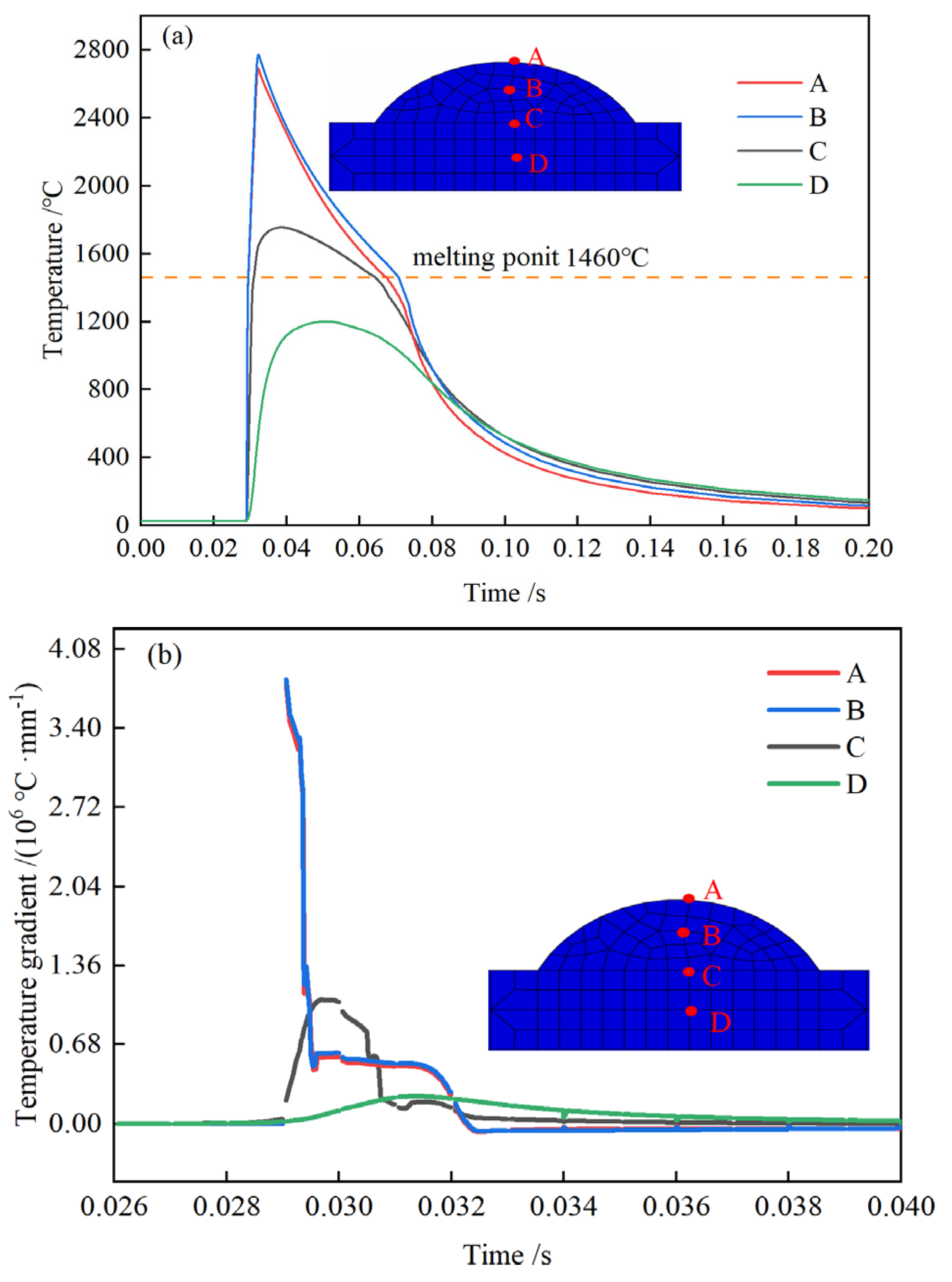
Figure 9 plots the thermal cycling curve and heating-cooling curve with four points in the direction of the molten pool section depth. From
Figure 9, we can deduce that the maximum cooling rate occurs between points A and B at the top of the molten pool, where the temperature is approximately 2780 °C and the cooling rate is approximately 3.8×10
6 °C/s; that the maximum temperature occurs between points C and D at the interface between the substrate and the molten layer, where the temperature is approximately 1753 °C and the cooling rate is approximately 8×10
5 °C/s; and that the maximum temperature occurs Intense convective heat transfer happens at the molten pool's surface, and heat accumulates in it, so the highest cooling rate is at the surface and the maximum temperature is within. Due to the exceptionally quick melting rate, the powder and substrate absorb less energy per unit time.
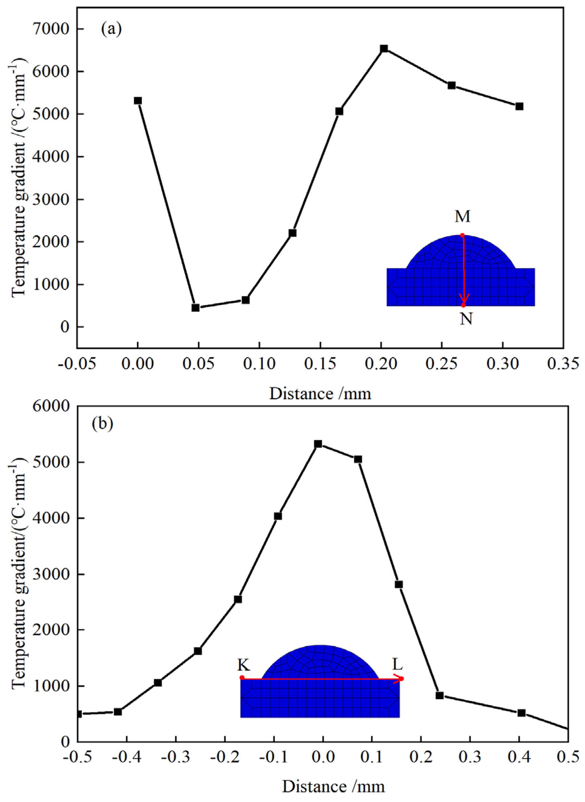
Figure 10(a) shows the temperature gradient from the molten pool's top, at 5231 °C /mm, to the bonding location between the coating and the substrate, at 6545 °C/mm, to the depths, at 457 °C/mm. The study demonstrates that the temperature difference is high because the molten pool's top is in contact with the air, its bottom is in contact with the base material, both of which are in contact with the overcooled item, and the pool itself has collected heat. The molten pool's temperature gradient is almost consistent over its width, as seen in
Figure 10 (b). At the edge of the molten layer and substrate combination, the heat absorbed by the material is low and the heat dissipation is serious, so the temperature gradient is low, about 500 °C/mm. At the center, due to the large heat input and the substrate material's lower temperature, the temperature gradient is high, up to 5321 °C /mm.
The cladding layer is cooled by a mixture of heat conduction from the substrate and air dispersion during the whole ultra-high speed laser cladding process. Both the solidification rate R
c and the temperature gradient G
n inside the cladding layer have an impact on its microstructure. A flat crystal structure forms with a high G
n/R
c ratio. When the ratio of G
n to Rc decreases, dendritic growth occurs [
22,
23].
Figure 11 depicts the microstructure of the single-track coating from top to bottom. The coating has three distinct layers: a layer of fine dendrites at the joint of the substrate, from which dendrites grow vertically at the top; a layer of dendrites that grow in the heat dissipation direction at the center; and a layer of small, uniform dendrites with random growth direction at the bottom. The inspection of
Figure 10 and
Figure 9 reveals that the convective heat transfer phenomena is clear and the heat loss is substantial owing to direct contact with air at the top, resulting in a quick reduction in temperature and a random distribution of grains throughout development.
4.4. Stress Field Simulation Analysis and Prediction
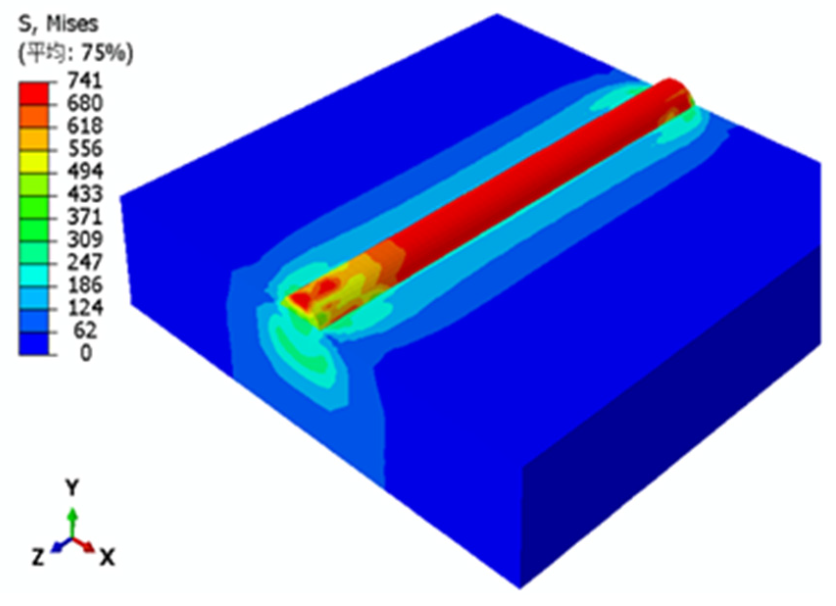
The residual stress distribution cloud map in
Figure 12 is obtained by first obtaining the results of a numerical simulation of the temperature field, then modifying the type of calculation unit, then loading the model with the results of the numerical simulation of the temperature field, and finally imposing boundary conditions on the stress field.
Figure 12 shows that the coating's residual stress is concentrated in the fusion coating region, with a maximum value of 741 MPa. This value is higher than the matrix's yield strength at the fusion layer and matrix bonding position, resulting in plastic deformation of the matrix. Cracking in fusion coatings is significantly affected by residual stress [
24,
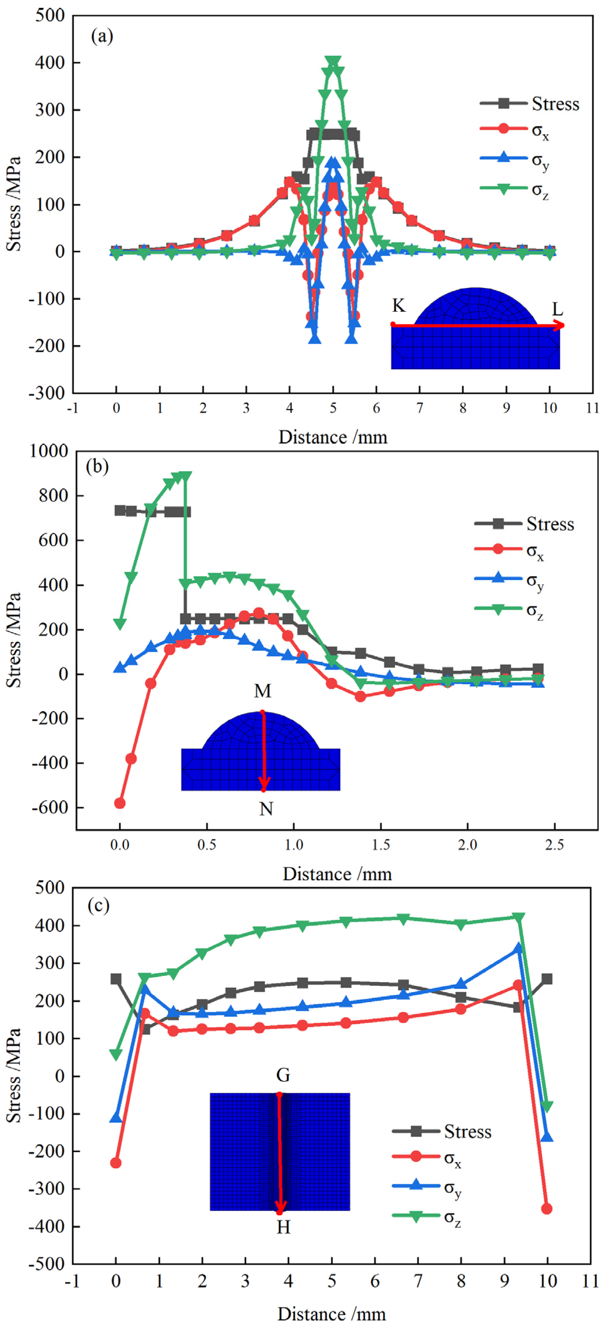
25]. As a result, we chose to examine the coating section pathways KL and MN, as well as the coating surface path GH.
Figure 13(a) depicts the residual stress curve along the KL-coated section route. Stress values on the coating are relatively large, with the tensile stress reaching a maximum of 406 MPa in the z-direction and the residual stress in the x-direction and y-direction changing from tensile stress to compressive stress along the KL path (as seen in
Figure 13 (a)). The stress in the melted layer region is relatively large, and the stress away from the melted layer is relatively small because of the extremely short action time of the laser in the melted layer region and the high cooling rate, which causes a relatively high temperature gradient at the symmetrical center of the melted layer and the material shrinkage phenomenon. A substantial residual stress is present in the coating bonding zone because of the substantial thermal expansion coefficient difference between the melted material and the substrate, as well as the uneven shrinkage.
The residual stress curve on the MN coating section route is shown in
Figure 13 (b).
Figure 13(b) shows that the cladding layer has a high residual stress throughout, with the highest residual stress of 741 MPa occurring at the interface between the cladding layer and the substrate. Maximum x-direction stress occurs at the cladding layer's top, whereas y-direction stress is often less intense and z-direction stress is greatest at the cladding layer's contact with the substrate. The coating's temperature differential is greatest at the cladding/substrate contact, and a substantial tensile tension is created when the melt pool rapidly cools and solidifies.
The coating's surface route GH is shown as a residual stress curve (
Figure 13(c)).
Figure 13(c) shows that the melt pool flows steadily throughout the cladding process, showing that the residual stress may be managed. This is shown by the fact that the stress and primary stress of the cladding surface fluctuate within a given range. In conjunction with
Figure 12(a), we can see that the surface residual stress is similar to that at the substrate/substrate interface (210 MPa), indicating no tendency of cracking in the coatings; however, the large residual stress in the z direction will increase the tendency of coating cracking.
5. Conclusions
(1) Abaqus finite element software was used to create a numerical model for ultra-fast laser cladding based on a composite heat source and the live-dead cell approach. Analysis of the effects of laser power and cladding speed on cladding section size and surface morphology was performed after a 431 stainless steel coating was clad onto a 45 steel shaft. Laser power of 2400 W, cladding speed of 20 m/min, and powder feeding rate of 20.32 g/min were chosen as the ideal process parameters for numerical simulation computation. The maximum temperature of the melt pool was calculated to be 2780 °C using this parameter and was found by a temperature field calculation. The numerical model was shown to be accurate since the predicted size and heat effect zone of the melt pool were in good agreement with the experimental data.
(2) To examine the cladding section's microstructure, a numerical simulation of temperature gradient and cooling rate was performed. The microstructure of the clad layer varied depending on its location: at the top, the cooling rate was highest, the temperature gradient was largest, and the clad layer's dendrite crystals were chaotic and fine; in the middle, the cooling rate was highest, the temperature gradient was smaller, and the clad layer's dendrite crystals were coarse and long.
(3) Cladding layer residual stress curve analysis was also performed. There was a lot of tension at the coating-substrate interface, more tension on the clad layer's surface than in its interior, and a lot of tension in the coating itself. The clad layer's residual stress mostly originated in the laser's scanning direction.
Author Contributions
Conceptualization, L.N. and M.W.; methodology, L.N. and X.W.; software, X.W. and L.N.; validation, L.N. and Y.X.; investigation, L.N.; resources, M.W.; data curation, L.N.; writing—original draft preparation, L.N.; writing—review and editing, X.W. and X.G.; supervision, M.W.; project administration, M.W.; funding acquisition, M.W. All authors have read and agreed to the published version of the manuscript.
Funding
The authors acknowledge funding support from the National Natural Science Foundation of China, under grant number 51975240.
Institutional Review Board Statement
Not applicable.
Informed Consent Statement
Not applicable.
Acknowledgments
All data are available from the corresponding author upon reasonable request.
Conflicts of Interest
The authors declare no conflict of interest.
References
- Chen, J.; Li, X.; Xue, Y. Friction and Wear Properties of Laser Cladding Fe901 Alloy Coating on 45 Steel Surface. Chin J Lasers 2019, 46. [Google Scholar] [CrossRef]
- Cao, W.; Li, Y.; Wang, Z. Study on Microstructure and Properties of Wear-resistant Coating on 45Steel Surface by Laser Cladding. Applied Laser 2022, 42, 41–47. [Google Scholar]
- Hu, Z.; Li, Y.; Liu, J.; etc. Research Progress of Ultra-High-Speed Laser Cladding Coating Forming and Key Properties. Laser Optoelectron P 2023, 60. [Google Scholar] [CrossRef]
- Koss, S.; Holzer, A.; Megahed, S.; etc. Investigation of the coating of hydrodynamic plain bearing contact surfaces by means of Extreme High-Speed Laser Material Deposition (EHLA). In 19TH DRIVE TRAIN TECHNOLOGY CONFERENCE (ATK 2021), 19th Drive Train Technology Conference (ATK), 2021; Vol. 1097.
- Ge, T.; Chen, L.; Gu, P.; etc. Microstructure and corrosion resistance of TiC/Inconel 625 composite coatings by extreme high speed laser cladding. Opt Laser Technol 2022, 150. [Google Scholar] [CrossRef]
- Schaible, J.; Sayk, L.; Schopphoven, T.; etc. Development of a high-speed laser material deposition process for additive manufacturing. J Laser Appl 2021, 33, 12021. [Google Scholar] [CrossRef]
- Schopphoven, T.; Gasser, A.; Wissenbach, K.; etc. Investigations on ultra-high-speed laser material deposition as alternative for hard chrome plating and thermal spraying. J Laser Appl 2016, 28. [Google Scholar] [CrossRef]
- Ding, Y.; Du, C.; Wang, X.; etc. Microstructure and interfacial metallurgical bonding of 1Cr17Ni2/carbon steel extreme high-speed laser cladding coating. Adv Compos Hybrid Ma 2021, 4, 205–211. [Google Scholar] [CrossRef]
- Shen, F.; Tao, W.; Li, L.; etc. Effect of microstructure on the corrosion resistance of coatings by extreme high speed laser cladding. Appl Surf Sci 2020, 517. [Google Scholar] [CrossRef]
- Hu, Q.; Wang, M.; Chen, Y.; etc. The Effect of MC-Type Carbides on the Microstructure and Wear Behavior of S390 High-Speed Steel Produced via Spark Plasma Sintering. Metals-Basel 2022, 12. [Google Scholar] [CrossRef]
- Dai, D.; Jiang, X.; Cai, J.; etc. Numerical Simulation of Temperature Field and Stress Distribution in Inconel718 Ni Base Alloy Induced by Laser Cladding. Chinese Journal of Lasers 2015, 42, 903001–903005. [Google Scholar]
- Li, L.; Shen, F.; Zhou, Y.; etc. Comparison of Microstructure and Corrosion Resistance of 431 Stainless Steel Coatings Prepared by Extreme High-Speed Laser Cladding and Conventional Laser Cladding. Chin J Lasers 2019, 46. [Google Scholar] [CrossRef]
- Wang, H.; Cheng, Y.; Geng, R.; etc. Comparative study on microstructure and properties of Fe-based amorphous coatings prepared by conventional and high-speed laser cladding. J Alloy Compd 2023, 952, 169842. [Google Scholar] [CrossRef]
- Zheng, H.; Wang, M.; Qiao, P.; etc. M2 Coatings Formed by Extreme High Speed Laser Cladding. Chin Surf. Engineering. 2022, 35, 191–202. [Google Scholar] [CrossRef]
- Lou, L.; Li, C.; Zhang, Y.; etc. Microstructure and surface morphology evolution of FeCr alloy thin coatingss deposited by ultra-high speed laser cladding with low laser power. J Yanshan University 2020, 44, 116–124. [Google Scholar] [CrossRef]
- Ding, Y.H.; Bi, W.Y.; Zhong, C.; etc. A Comparative Study on Microstructure and Properties of Ultra-High-Speed Laser Cladding and Traditional Laser Cladding of Inconel625 Coatings. Materials 2022, 15. [Google Scholar] [CrossRef] [PubMed]
- Li, T.; Zhang, L.; Chen, G.; etc. A combined heat source model for the prediction of residual stress post extreme high-speed laser material deposition. J Manuf Process 2022, 78, 265–277. [Google Scholar] [CrossRef]
- Li, T.; Zhang, L.; Chen, G.; etc. Eigenstrain reconstruction of residual stress and its application in extreme high-speed laser material deposition. J Manuf Process 2023, 85, 1054–1065. [Google Scholar] [CrossRef]
- Guo, W.; Jian, H.; Chai, R.; etc. Numerical Simulation and Verification of Laser Cladding on 27SiMn Steel Surface. Hot Working Technology 2016, 45, 1–6. [Google Scholar]
- Walker, T.R.; Bennett, C.J.; Lee, T.L.; etc. A validated analytical-numerical modelling strategy to predict residual stresses in single-track laser deposited IN718. Int J Mech Sci 2019, 151, 609–621. [Google Scholar] [CrossRef]
- Li, T.C.; Zhang, L.L.; Chen, G.; etc. A combined heat source model for the prediction of residual stress post extreme high-speed laser material deposition. J Manuf Process 2022, 78, 265–277. [Google Scholar] [CrossRef]
- DebRoy, T.; Wei, H.L.; Zuback, J.S.; etc. Additive manufacturing of metallic components – Process, structure and properties. Prog Mater Sci 2018, 92, 112–224. [Google Scholar] [CrossRef]
- Raghavan, A.; Wei, H.L.; Palmer, T.A.; etc. Heat transfer and fluid flow in additive manufacturing. J Laser Appl 2013, 25. [Google Scholar] [CrossRef]
- Xie, L.; Shi, W.; Wu, T.; etc. Numerical Simulation of Temperature Field and Stress Field of Laser Cladding on Curved Substrate Workpiece. Surface Technology 2022, 51, 296–303, 325. [Google Scholar]
- Zhang, T.; Zhang, Q.; Yao, B.; etc. Numerical Simulation of Temperature Field and Stress Field of Ni-Based Laser Cladding Layer on TC4 Surface. Laser Optoelectron P 2021, 58. [Google Scholar] [CrossRef]
|
Disclaimer/Publisher’s Note: The statements, opinions and data contained in all publications are solely those of the individual author(s) and contributor(s) and not of MDPI and/or the editor(s). MDPI and/or the editor(s) disclaim responsibility for any injury to people or property resulting from any ideas, methods, instructions or products referred to in the content. |
© 2023 by the authors. Licensee MDPI, Basel, Switzerland. This article is an open access article distributed under the terms and conditions of the Creative Commons Attribution (CC BY) license (http://creativecommons.org/licenses/by/4.0/).
