Submitted:
21 April 2023
Posted:
21 April 2023
You are already at the latest version
Abstract
Keywords:
1. Introduction
2. Proposed NdFeB Magnet Configuration
2.1. Proposed Magnet Design Approach
2.2. Step-Skewed Rotor
3. Characteristic Comparison of Voltage and Torque
3.1. Cogging Torque Minimization with Step-Skew
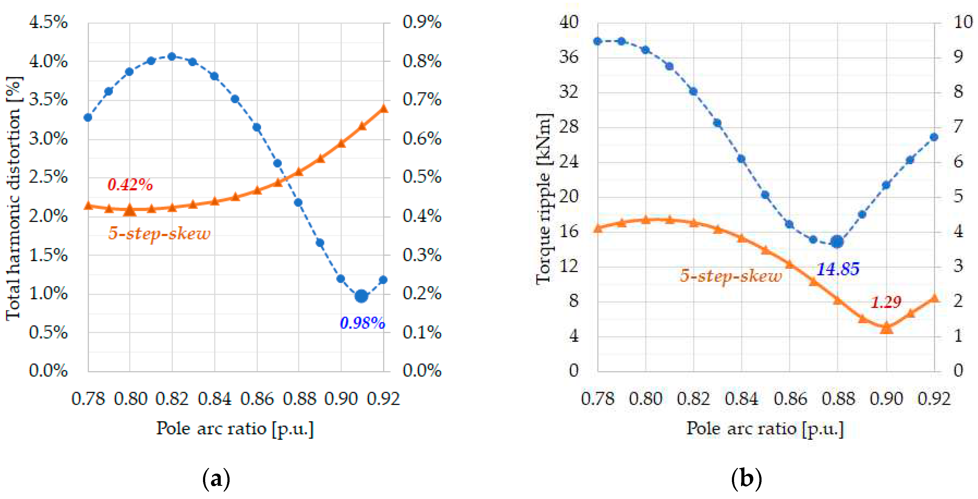
3.2. Harmonic Minimization in Voltage and Torque Ripple
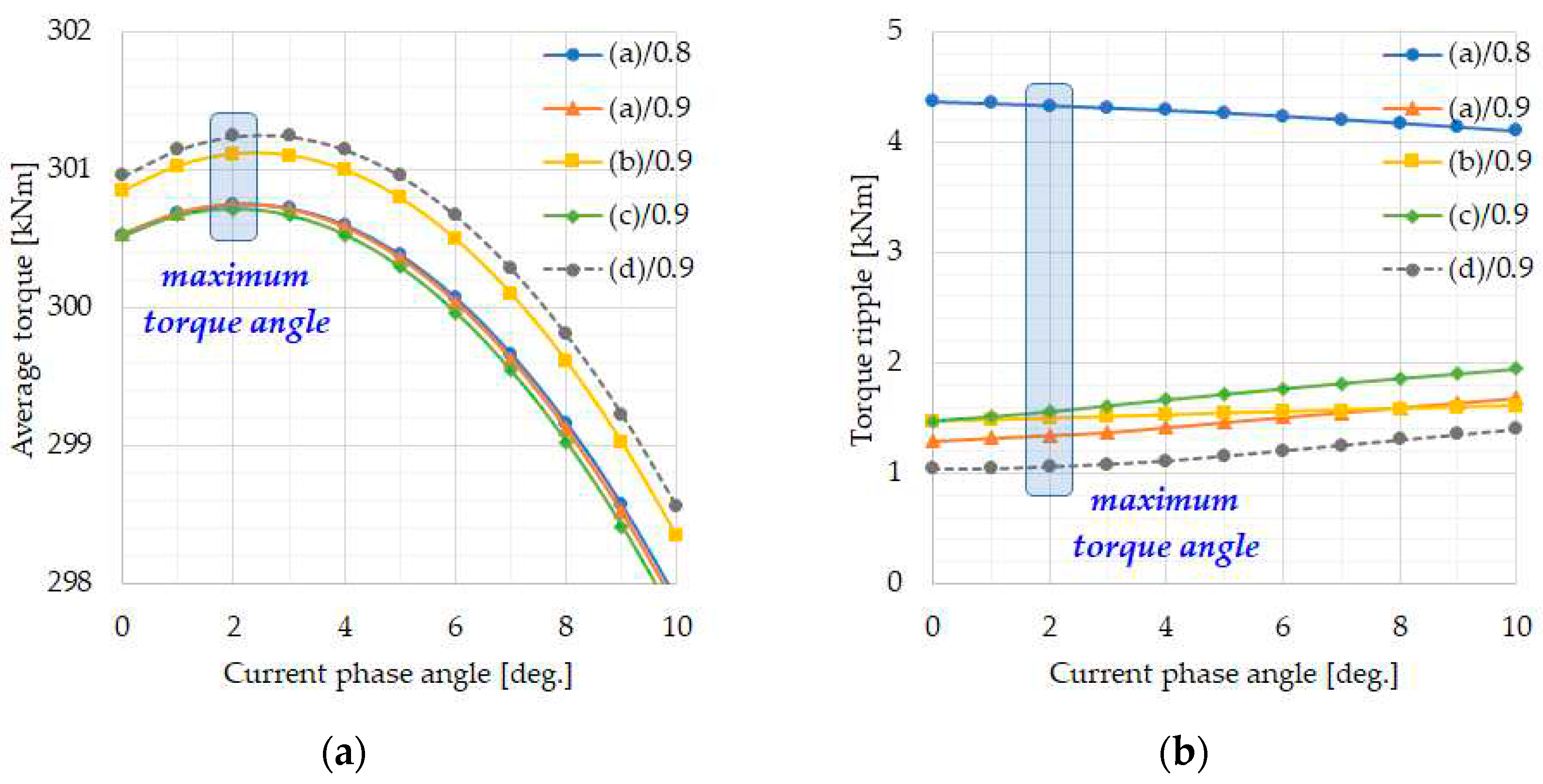
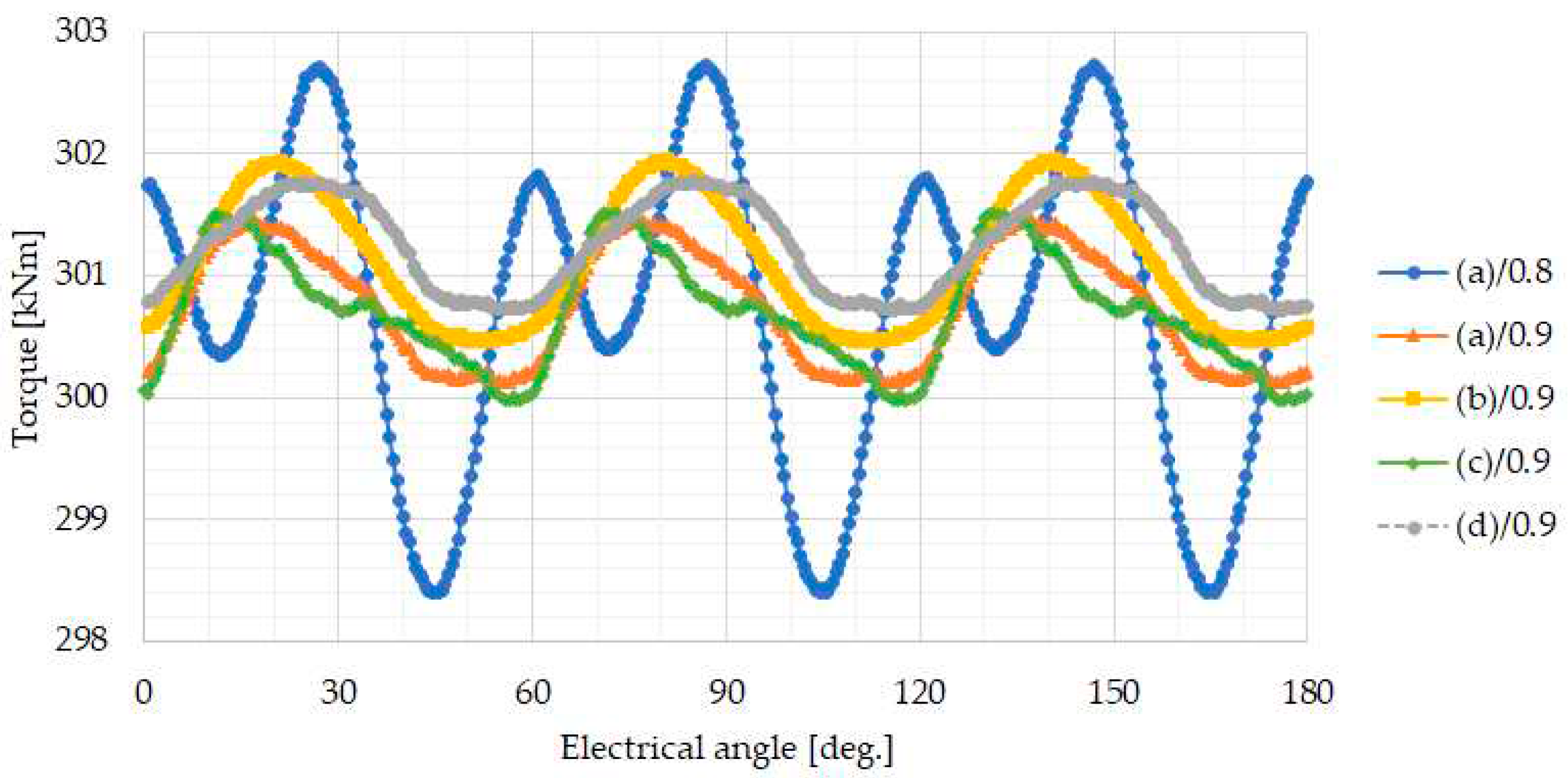
3.3. Characteristic Comparison of Four Different Magnet Designs
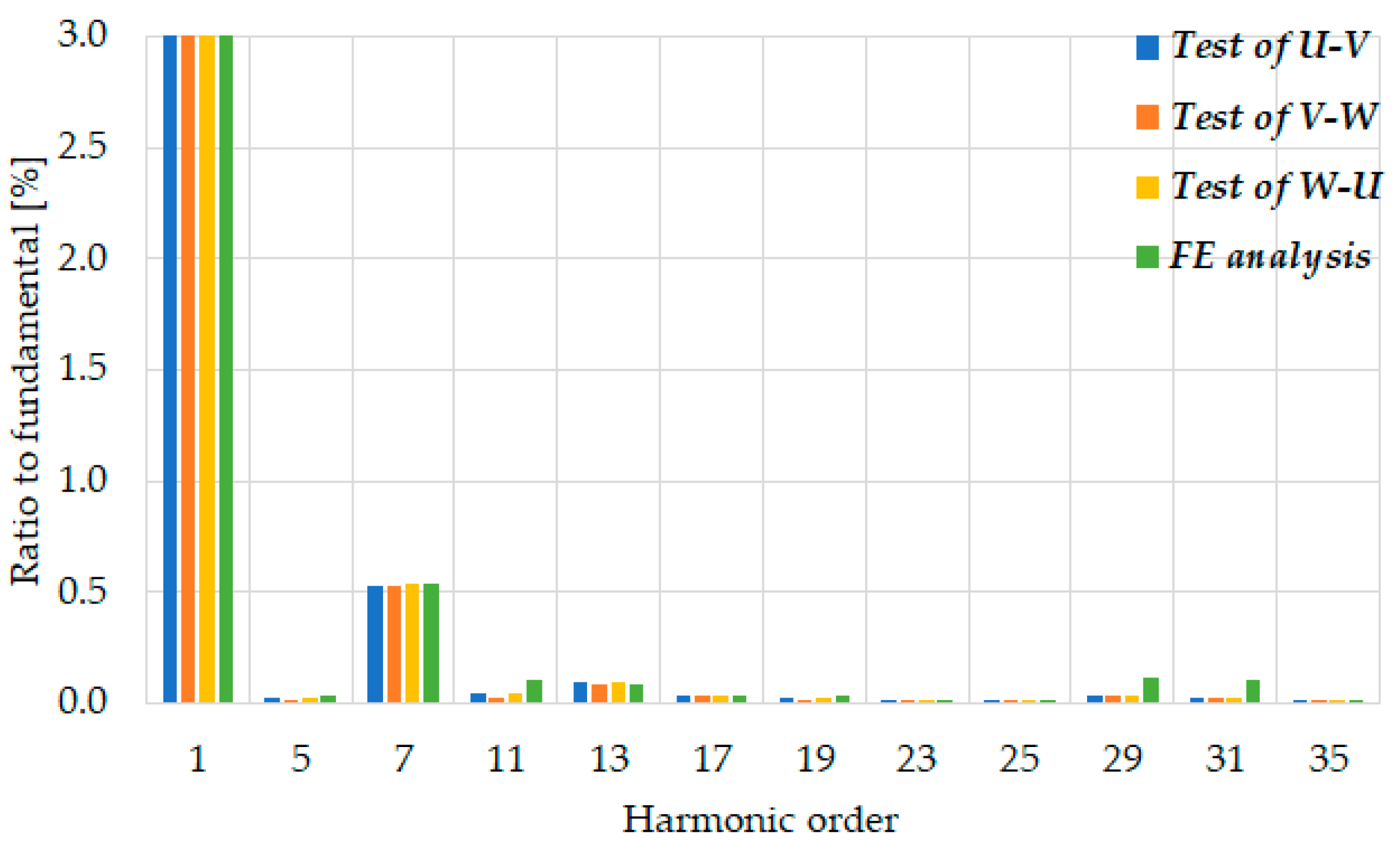
4. Model Validation of Finite Element Method
5. Conclusions
References
- Zhu, Z.Q.; Shen, Y. Investigation of permanent magnet brushless machines having unequal-magnet height pole. IEEE Trans. Magn. 2012, 48, 4815-4830. [CrossRef]
- Zhu, Z.Q.; Howe, D. Halbach permanent magnet machines and applications: a review. IEE Proc.-Elect. Power Appl. 2001, 148, 299-308. [CrossRef]
- Chaithongsuk, S.; Takorabet, N.; Meibody-Tabar, F. On the use of pulse width modulation method for the elimination of flux density harmonics in the air-gap of surface PM motors. IEEE Trans. Magn. 2009, 45, 1736-1739. [CrossRef]
- Li, Y.; Xing, J.; Wang, T.; Lu, Y. Programmable design of magnet shape for permanent-magnet synchronous motors with sinusoidal back EMF waveforms. IEEE Trans. Magn. 2008, 44, 2163-2167. [CrossRef]
- Hsieh, M.F.; Hsu, Y.S. An investigation on influence of magnet arc shaping upon back electromotive force waveforms for design of permanent-magnet brushless motors. IEEE Trans. Magn. 2005, 41, 3949-3951. [CrossRef]
- Zheng, P.; Jing, Z.; Jianqun, H.; Jie, W.; Zhiyuan, Y.; Ranran, L. Optimization of the magnetic pole shape of a permanent-magnet synchronous motor. IEEE Trans. Magn. 2007, 43, 2531-2533. [CrossRef]
- Tavana, N.R.; Shoulaie, A. Analysis and design of magnetic pole shape in linear permanent-magnet machine. IEEE Trans. Magn. 2010, 46, 1000-1006. [CrossRef]
- Laskaris, K.I.; Kladas, A.G. Permanent-magnet shape optimization effects on synchronous motor performance. IEEE Trans. Ind. Elect. 2011, 58, 3776–3783. [CrossRef]
- Zhu, Z.Q.; Wang, K.; Ombach, G. Optimal magnet shaping with third order harmonic for maximum torque in brushless AC machines. IET Int. Conf. Power Elect. 2012, 1-6. [CrossRef]
- Wang, K.; Gu, Z.Y.; Zhu, Z.Q.; Wu, Z.Z. Optimum injected harmonics into magnet shape in multiphase surface-mounted PM machine for maximum output torque. IEEE Trans. Ind. Elect. 2017, 64, 4434-4443. [CrossRef]
- Ree, J.D.L.; Boules, N. Magnet shaping to reduce induced voltage harmonics in PM machines with surface mounted magnets. IEEE Trans. Energy Convers. 1991, 6, 155-161. [CrossRef]
- Dubois, M.R.; Mailloux, G. Analytical calculation of no-load voltage waveforms in machines based on permanent-magnet volume integration. IEEE Trans. Magn. 2008, 44, 581-589. [CrossRef]
- Isfahani, A.H.; Vaez-Zadeh, S.; Rahmanm M.A. Using modular poles for shape optimization of flux density distribution in permanent-magnet machines. IEEE Trans. Magn. 2008, 44, 2009-2015. [CrossRef]
- Hwang, S.; Lieu, D.K. Design techniques for reduction of reluctance torque in brushless permanent magnet motors. IEEE Trans. Magn. 1994, 30, 4287-4289. [CrossRef]
- Islam, M.S.; Shrestha, A.; Islam, M. Performance comparison of step skew in interior and surface-mount permanent magnet machines. IEEE Energy Conves. 2021. [CrossRef]
- Ocak, O.; Aydin, M. An innovative semi-FEA based, variable magnet-step-skew to minimize cogging torque and torque pulsations in permanent magnet synchronous motors, IEEE Access. 2020, 8, 210775-210783. [CrossRef]
- Nam, D.W.; Lee, K.B.; Pyo, H.J.; Jeong, M.J.; Yang, S.H.; Kim, W.H.; Jang, H.K. A study on core skew considering manufacturability of double-layer spoke-type PMSM. Energies. 2021. 14, 610. [CrossRef]
- Jiang, J.W.; Bilgin, B.; Yang, Y.; Sathyan, A.; Dadkhah, H.; Emadi, A. Rotor skew pattern design and optimisation for cogging torque reduction. IET Elect. Syst. Transp. 2016, 6, 126-135. [CrossRef]



| Design Variable | Unit | Specifications |
|---|---|---|
| Rated power | kVA | 2,100 |
| Rated speed | rpm | 65 |
| Number of phases | - | 3 |
| Number of poles | - | 32 |
| Number of slots | - | 192 |
| Stator outer diameter | mm | 2,310 |
| Stator inner diameter | mm | 2,000 |
| Minimum air-gap length | mm | 6 |
| Maximum magnet height | mm | 24 |
| Rotor rim height | mm | 50 |
| Core length except radial ducts | mm | 900 |
| Number of core packet | EA | 20 |
| Core material | - | 50PN400 |
| Skew angle | no. of slot | One slot pitch on rotor |
| Pole Arc Ratio |
Maximum Air-Gap Length |
Remanence of Center Magnet |
Remanence of Edge Magnet |
THD of Induced Voltage |
Torque Ripple |
|---|---|---|---|---|---|
| p.u. | mm | T | T | % | % |
| 0.80 | 7 | 1.267 | 1.000 | 0.34 | 1.18 |
| 8 | 1.297 | 1.000 | 0.33 | 1.10 | |
| 9 | 1.326 | 1.000 | 0.35 | 1.16 | |
| 0.89 | 9 | 1.255 | 1.000 | 0.31 | 0.48 |
| 10 | 1.275 | 1.000 | 0.31 | 0.43 | |
| 11 | 1.294 | 1.000 | 0.34 | 0.42 | |
| 0.90 | 9 | 1.250 | 1.000 | 0.35 | 0.59 |
| 10 | 1.269 | 1.000 | 0.35 | 0.51 | |
| 11 | 1.287 | 1.000 | 0.37 | 0.41 | |
| 12 | 1.305 | 1.000 | 0.40 | 0.35 | |
| 13 | 1.322 | 1.000 | 0.43 | 0.36 |
| Rotor Topology |
Pole Arc Ratio |
Maximum Air-Gap Length |
Remanence of Center Magnet |
THD of Induced Voltage |
Average Torque |
Torque Ripple |
| p.u. | mm | T | % | kNm | % | |
| Conventional bread-loaf magnet | 0.90 | 6 | 1.189 | 0.59 | 300.5 | 0.43 |
| Tapered bread-loaf magnet | 0.90 | 12 | 1.273 | 0.29 | 300.8 | 0.49 |
| Rectangular magnet | 0.90 | 6 | 1.380 | 0.74 | 300.5 | 0.49 |
| Proposed modular pole | 0.89 | 10 | 1.275 | 0.31 | 300.8 | 0.43 |
| 0.90 | 12 | 1.305 | 0.40 | 301.0 | 0.35 |
Disclaimer/Publisher’s Note: The statements, opinions and data contained in all publications are solely those of the individual author(s) and contributor(s) and not of MDPI and/or the editor(s). MDPI and/or the editor(s) disclaim responsibility for any injury to people or property resulting from any ideas, methods, instructions or products referred to in the content. |
© 2023 by the authors. Licensee MDPI, Basel, Switzerland. This article is an open access article distributed under the terms and conditions of the Creative Commons Attribution (CC BY) license (http://creativecommons.org/licenses/by/4.0/).


