1. Introduction
Water is an essential resource in our day-to-day life. As we all know, the Earth surface consists of three parts of water and one part of land and the sweet water is only 3% of the total water quantity [
1]. The water level control in a tank aims at avoiding the waste of the water used for irrigation or for home consumers. This will also contribute to an efficient usage of the resources by reducing the water consumption and, by default, of the energy needed for pumping the water from the source to consumers. The works [
2,
3] present each an automatic system of water level control based on Arduino Uno and 7-segment BCD display. Intelligent control systems for plant cultivation through the control of water pumping devices are presented in the works [
4,
5,
6]. The automatic system for water level adjustment in a tank based on Arduino Uno is simulated by means of the Proteus program in the works [
7,
8]. The water level measurement in a tank is done in the work [
9] by means of discrete elements. The work [
10] presents the usage of the LabVIEW program for controlling the water level in a tank. An automatic control system of the water level in a tank with flexible indicator equipped with a micro controller is presented in the work [
11]. The work [
12] describes a water level automatic control system based on Arduino Uno and a GSM module. In the work [
13] the development board Arduino Uno is used for a pressure measuring system whilst in the work [
14] an automatic system for controlling the water level in a glass house is presented. The work [
15] describes an automatic system for controlling the water level in a tank through a mobile phone and the work [
16] presents the water level measurement in a fountain through Raspberry PI board. A semi-automatic irrigation system based on Arduino is presented in the work [
17]. In the work [
18], the control of the water level in a tank is performed by means of a micro controller and the measured value is transmitted from a distance through radio waves.
1.1. Priority of the Research
The usage of the system IoT (internet of Things) offers many applications nowadays that help with improving the day-to-day life. The work [
19] presents an intelligent system for water quality monitoring through the efficient usage of a IoT. A IoT based infrastructure for intelligent monitoring of the air quality in industrial environments is presented in the work [
20]. A monitoring and control system based on IoT for glass houses is shown in the works [
21,
22]. For this reason I used in this work a IoT system equipped with the development board NodeMCU ESP8266 for monitoring the water level in the tank by collecting the data from the ultrasonic sensor HC-SR04 and their transmission on a Website built on the Thingspeak platform. In this manner the human operator will be able to follow up the water level in the tank at any moment. The Thingspeak platform is a free platform that allows the definition of eight channels for data collection from sensors by means of the circuit NodeMCU ESP8266. Based on this online information about the water level in the tank, the operator will have the possibility to program the water supply for the home consumers or irrigation systems in function of the existing water reserve.
1.2. Contributions to the Work Achievement
The purpose of this work is to present a prototype for controlling and monitoring the water level in a tank by making use of performant equipment at low costs that could allow the usage of artificial intelligence elements such as: implementation of control algorithms of the water level in the tank, online monitoring of the level through Internet and control through the mobile phone of the supply pump. This work presents a prototype that combines three different applications for the water management in a tank, namely:
- -
Water level control in the tank
- -
Monitoring the water level in the tank
- -
Control through the mobile phone of the consumer water supply pump.
For the above three applications programs have been issued in the programming environment Arduino IDE. The main advantage of this prototype consists of the fact that it provides a control at an accuracy of 0,3 cm al of the water level in the tank at a low price of the equipment being used. At the same time, this prototype has a universal character. It does not require any hardware modification in case of usage for other tanks, software changes only in terms of the parameters to be controlled. The disadvantage of this protype is that it requires a powerful Wi-Fi signal for data transmission from the development board NodeMCU ESP8266 to the platform ThingSpeak. The references being quoted in this work do not present an alike prototype for the water management in a tank. This control and monitoring system has, as main purpose, the elimination of the water losses and may be implemented in the irrigation systems or in the water supply systems for home consumers.
2. Materials and Methods
2.1. Description of the Experimental Stand
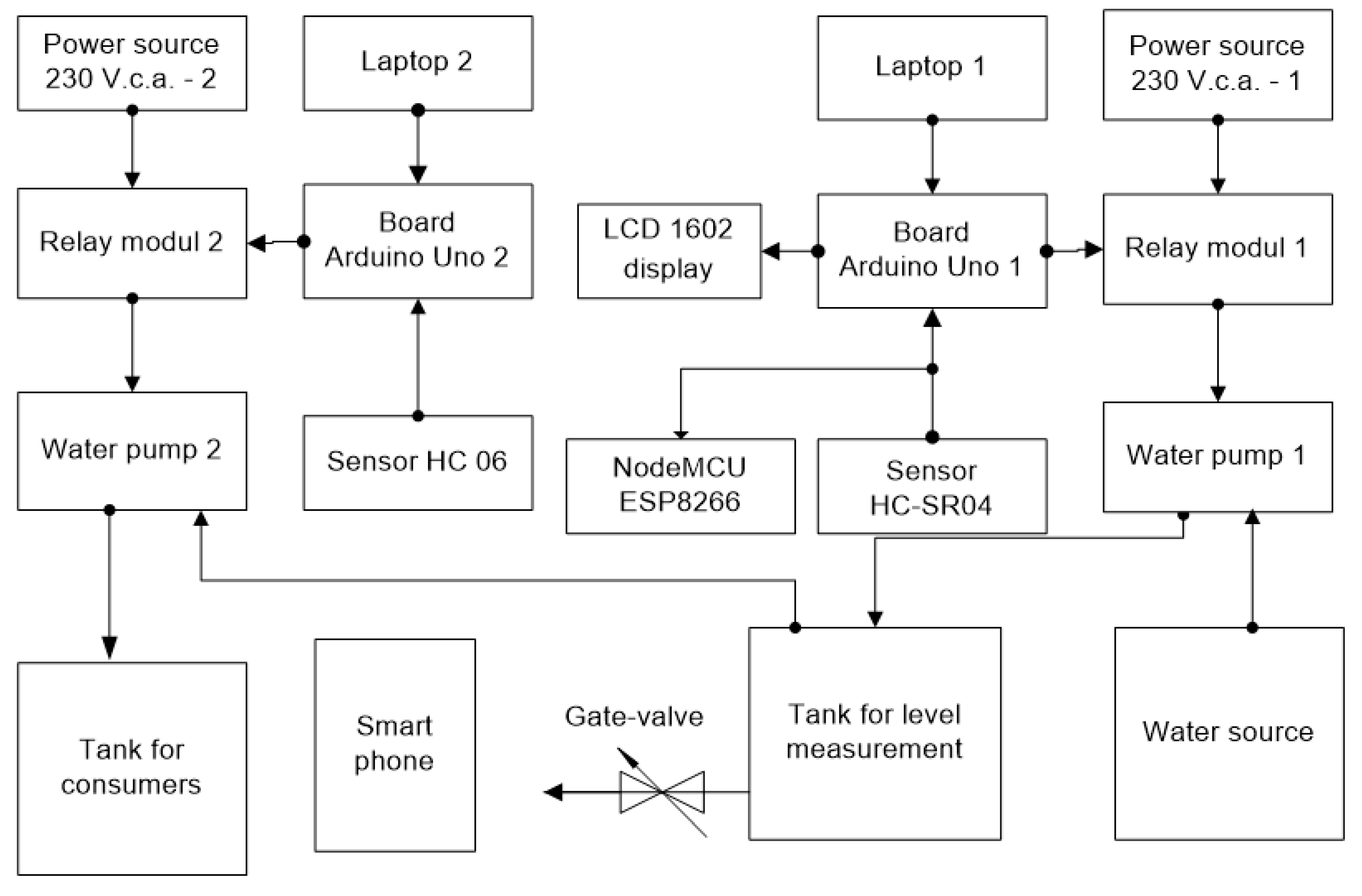
The block diagram of the experimental stand for measuring the water level in a tank is shown in
Figure 1. The experimental stand is composed of the following: - Laptop, 2 pcs; - Development board Arduino Uno, 2 pcs; - Ultrasonic sensor HC-SR04, 1pc; - Relay module, 2 pcs; - Vibrator pump, 2pcs; - Broadboard, 2 pcs; - LCD 1602 display, 1 pc; development board NodeMCU ESP8266, 1 pc - Power source of 230 V a. c.; - Water tank; - Water source, Bluetooth sensor HC-06, 1 pc, Smartphone -1 pc.
2.2. Development Board Arduino Uno
The development board Arduino Uno is built with the microcontroller ATmega328P, [
23]. The works [
24,
25] are presenting the functioning principle of the development board Arduino Uno and the programming mode. The work [
26] describes several applications made with the development board Arduino Uno and the programming techniques of the microcontroller. The supply voltage of the board may vary within (7-12) V d. c. The microcontroller Atmega 328P is supplied at voltage of 5 V d. c. The development board Arduino Uno may be connected to a laptop by means of a USB port. The board Arduino Uno features 6 pins for analogic inputs and 14 pins for digital inputs/outputs. 6 of these pins may be set as outputs for PWM type signals. The microcontroller ATmega 328 has 32 KB of flash memory out of which 0,5 KB are used by bootloader, 2 KB of SRAM memory and 1 KB of EEPROM memory.
2.3. Ultrasonic sensor HCSR04
The work [
27] presents a study of the distance sensor performance. The work [
28] presents a study on the application of the algorithm KF for the ultrasonic sensor HC-SR04 in order to lower the noise. The ultrasonic sensor HC-SR04 is supplied at a voltage of 5 V d. c. and can measure a distance ranging within (2- 400) cm at a resolution of 0,3 cm. The measurement angle of this sensor is 30 degrees. From [
27] shows that this sensor has 4 pins, as follows: VCC, Trig, Echo and GND. The ultrasonic sensor is supplied through the pins VCC and GND at a voltage of 5 V d. c. The sensor sends ultrasounds of 40 kHz frequency from the pin Trig. The ultrasounds are emitted in the air and, if obstacles are met, the signals will return to the module and will be received at the pin Echo. The measured distance will be given by the relation:
where: D – measured distance, t – duration, v – sound speed. Sound speed = 340 m/s. In case of using the sensor for level measurement, the signals sent by the sensor will be reflected by a floater located on the water surface in the tank. The floater will be made of an opaque material of a density much lower than the water density.
2.4. Relay Module
This module includes an electromechanical relay through which the supply of an electrical device at high voltage and intensity rates can be controlled. The relay module is supplied at 5 V d. c. through the pins VCC and GND and the control signal from a digital pin of the development board Arduino Uno is applied to the pin INT. The normally open (ND) contact of the relay will be inserted to the pump supply circuit from a source of 230 V a. c. The pump supply circuit will close when the pin INT will receive a signal of 5 V d. c. from the board Arduino Uno.
2.5. ULKA Vibrating Pump
The vibrating pump ULKA used for water supply of the tank has the following features: Supply voltage = 230 V a. c., Frequency = 50 Hz, Consumption power = 48 W, Maximum pressure = 15 bar, Maximum flow = 650 cc/min.
2.6. LCD 1602 Digital Display
The digital display LCD 1602 is used for displaying texts. Texts made of 32 characters may be displayed, 16 on each one of the two available lines. Each character is, in fact, a matrix of 5x8 points. The LCD 1602 display is connected to the board Arduino Uno by means of the interface I2C.
2.7. NodeMCU ESP8266
NodeMCU ESP8266 is a development board of opensource type. The main role of this development board is to provide stable connections of
Wireless type among multiple devices and even to serve itself as an access point in several cases. The development board NodeMCU ESP8266 can be programmed such as to achieve various tasks that need Internet access and the programming language being used is C/C++. The applications written in C/C++ will be loaded in the flash memory of the device through
Arduino IDE (Integrated Development Environment),[
29]. This board can also be used in applications of the type: application programming interface (
API). An API application can be for a web system, an operation system, a data base system, hardware or software libraries. This
open-source type device allows multiple loadings of the source code. The development board NodeMCU is composed of an integrated circuit ESP8266 Wi-Fi activated. The integrated circuit ESP8266 has been developed by Espressif Systems at low costs and is provided with a TCP/IP protocol. The board NodeMCU ESP8266 is supplied at a voltage of 3.3 V d. c. and has 17 GPIO pins that can be allotted for various peripheral tasks. To the board NodeMCU ESP 8266 will be connected the same ultrasonic sensor used for measuring the water level in the tank through the development board Arduino Uno.
3. Results
3.1. Running of the Experimental Stand for Level Control and Monitoring
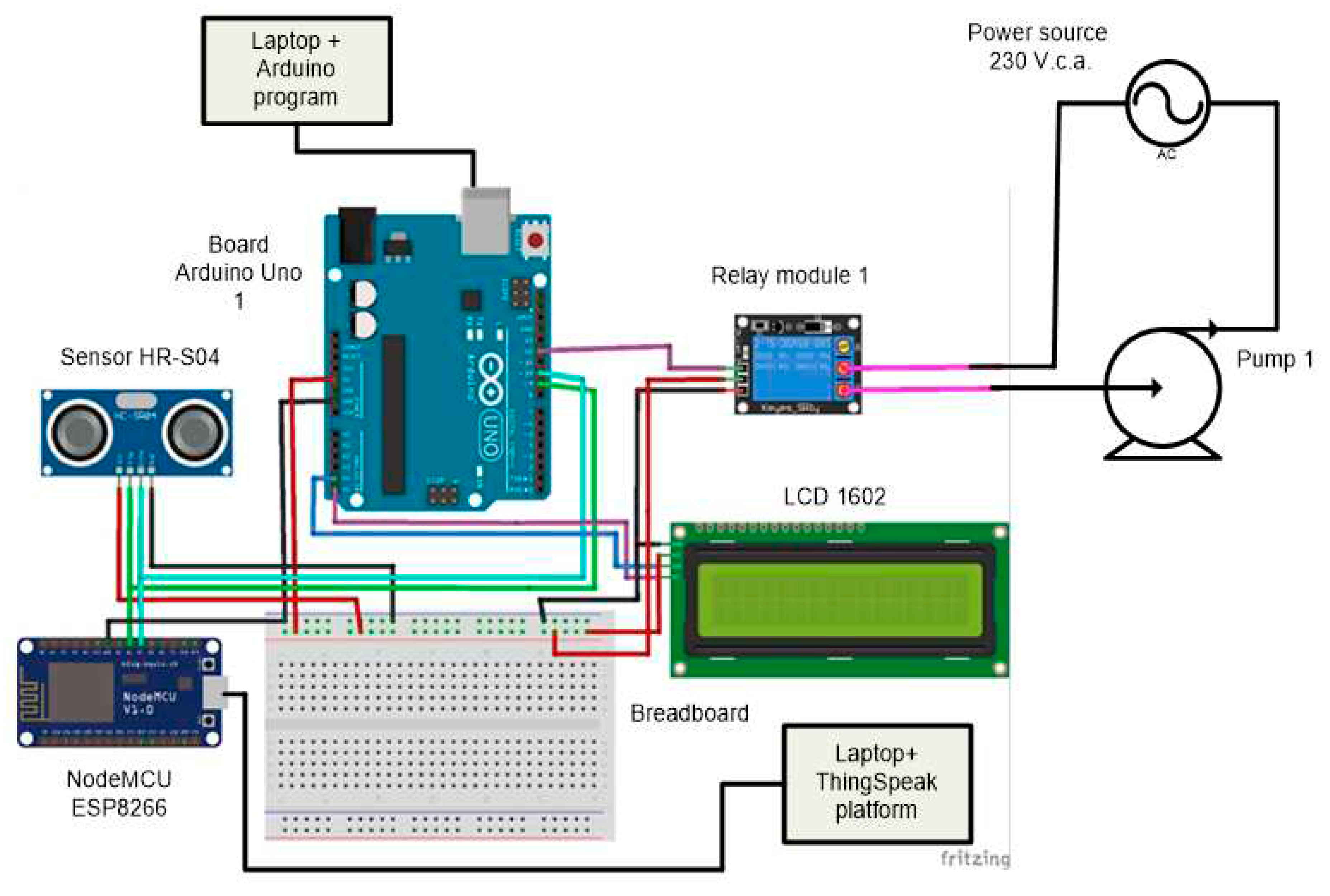
The electric diagram of the experimental stand for the level control and monitoring built in the Electrical Machinery and Drives laboratory of the Engineering Faculty in Bacau is shown in
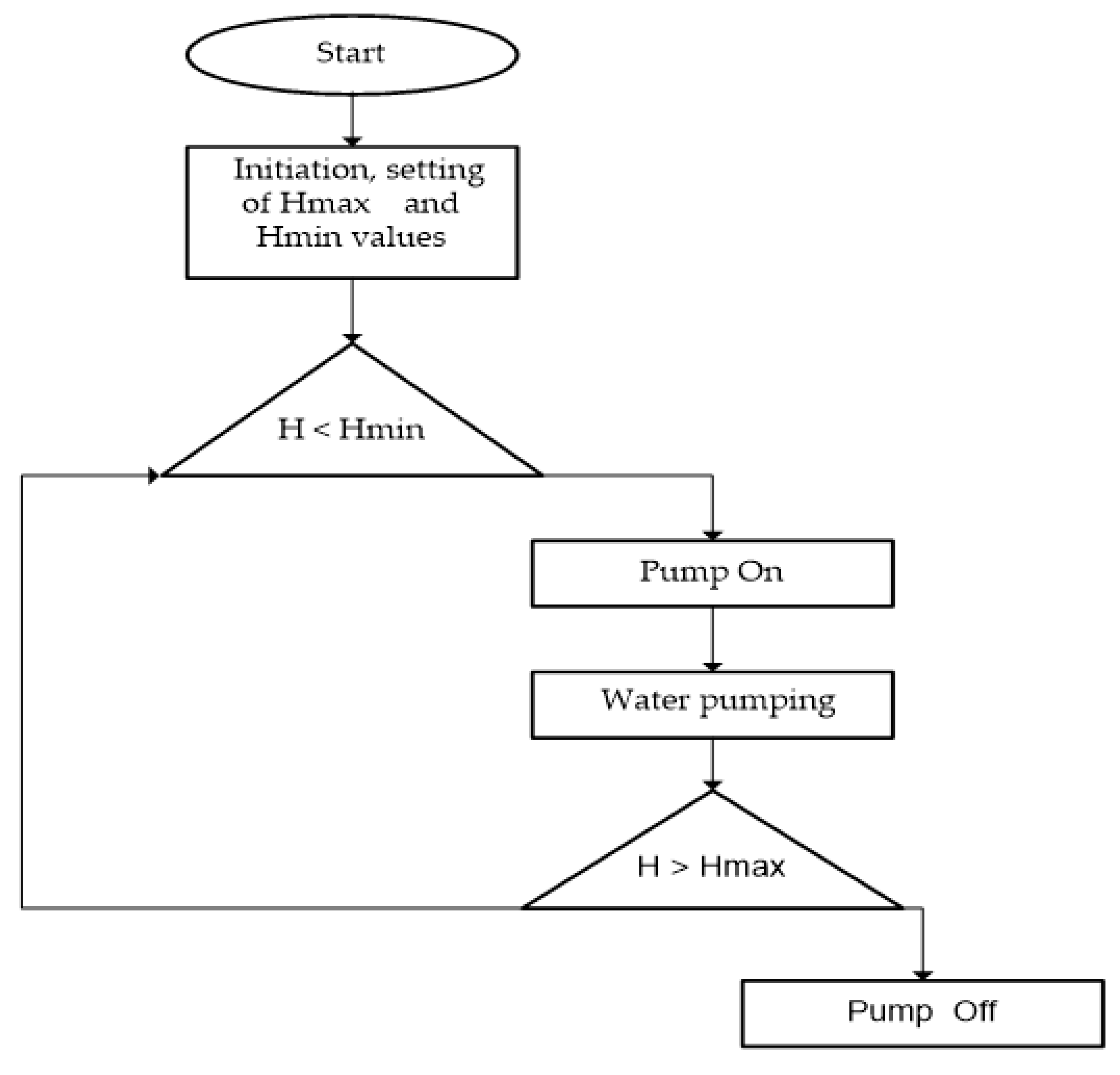
Figure 2. The water level in the tank is measured with the ultrasonic sensor HC-SR04 located on top of the tank. Practically, it measures the distance from the sensor to the floater located above the water in the tank, by means of the program stored in the flash memory of the microcontroller ATmega 328 belonging to the structure of the development board Arduino Uno. The measured value of the water level will be displayed on the LCD 1602 screen. The maximum and minimum values of the water level in the tank are to be settled in function of the tank dimensions and volume of water necessary for consumers. The water level in tank can be controlled by means of the algorithm being presented in the diagram from
Figure 3. If the water level in the tank is lower than Hmax, a command will be issued by the Arduino board to the relay module and the normally open (ND) contact of the relay located in the supply circuit will shut on, the pump will start and water will be pumped from the source to the tank. When the water level in the tank is higher than Hmin, the command issued by the Arduino board to the relay module and the normally open (ND) contact will open and the pump will be stopped. This algorithm will repeat until the running of the program stored in the flash memory of the microcontroller will be stopped.
The information received from the ultrasonic sensor HC-SR04 is also collected by the development board NodeMCU ESP 8266 that will send it to the ThingSpeak through Wi-Fi. By means of a channel of the ThingSpeak platform the variation of the water level in the tank will be displayed in real time. The channel of the ThingSpeak may be set for access in private or public regime. The tank is supplied with water with the help of a pump from a water source, such as a fountain, lake, river etc. The water tank whose level is to be measured has to be located in a high place so that the water to be able to reach the home consumers or the irrigation systems through free falling as well. In the case of this work, a ULKA vibrator pump with the same characteristics as the pump used in the construction of the experimental stand for measuring the water level in the tank was introduced into the water supply circuit of domestic consumers or irrigation systems. This pump is remotely controlled via smart phone.
The reach of the water maximum level in the tank imposed through the program has always led to stopping the pump.
Figure 3.
Control algorithm of the water level in the tank.
Figure 3.
Control algorithm of the water level in the tank.
3.2. Remote Control through the Mobile Phone of the Water Supply Pump
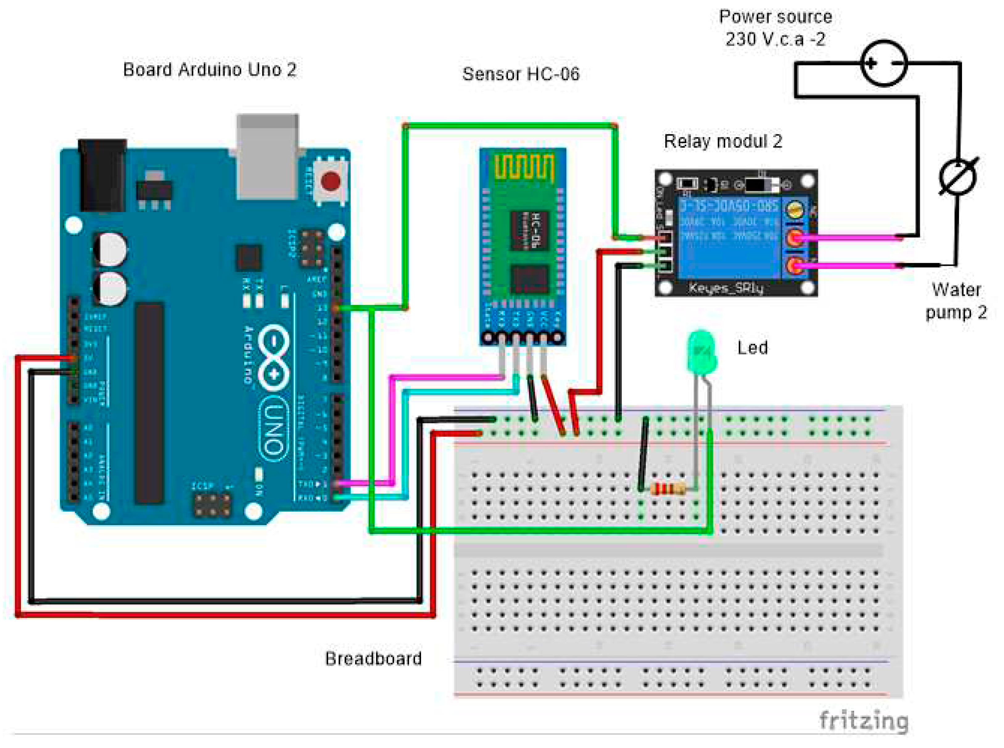
The water in the tank may be used for supplying home consumers or irrigation systems. For controlling the vibrating pump ULKA that equips the water supply circuit, a device has been used that is composed of a development board Arduino Uno, un a Bluetooth sensor HC-06 and a relay module. The electric diagram of the remote control device for the vibrating pump ULKA is shown in
Figure 4. The works [
30,
31] are presenting applications of the bluetooth sensor HC-06 for a smart house or for an irrigation system. The Bluetooth sensor HC-06 has the following features: - provision of wireless data communication within the frequency range 2,402-2,480 GHz. – supply from a power source of 5V d. c. -the pin TXD is intended for data transmission and the RXD pin is for data receival. The remote control by means of the mobile phone through the Arduino Bluetooth Control is downloaded from Google Play. For the application Arduino Bluetooth Control the mobile phone Samsung Galaxy A 12 will be connected in the Switch mode to the device BT04-A corresponding to the Bluetooth module HC-06. For switching ON and OFF the supply of the vibrating pump the commands START and STOP will be issued from the mobile phone. The control signal coming from the mobile phone will be received by the
Bluetooth sensor HC-06 that will control the relay module connected to the development board Arduino Uno. The normally open (ND) contact of the relay will be inserted to the supply circuit of the vibrating pump from the power source of 230 V a. c.
3.3. Experimental Results
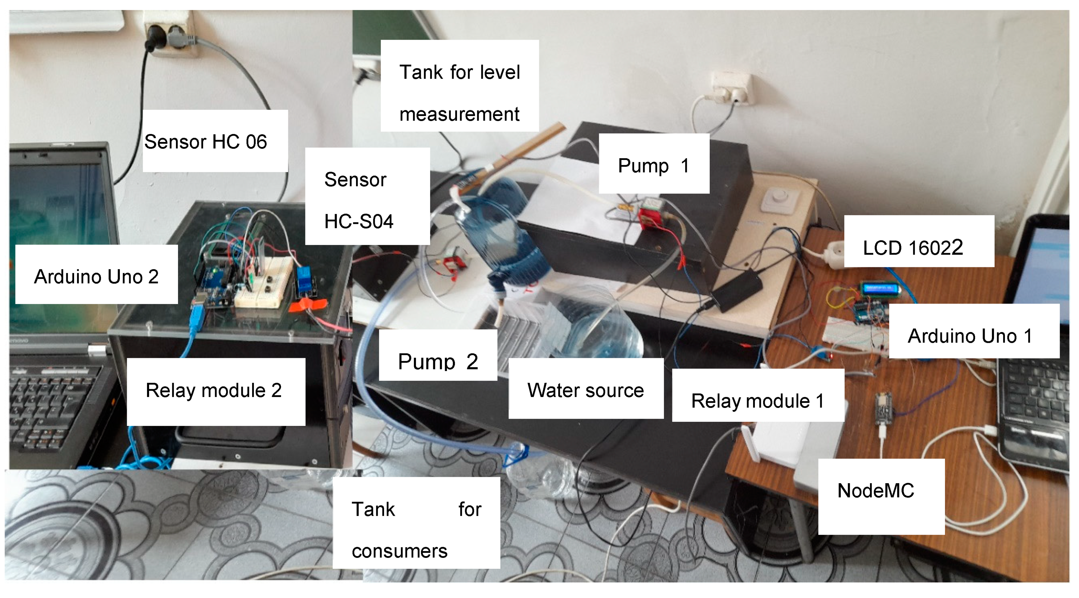
A picture of the experimental stand for controlling and monitoring the water level in the tank is presented in
Figure 5 For building the experimental stand a tank of 2,3 litres volume and 15 cm diameter has been used. The ultrasonic sensor HC-SR04 is fixed above the tank. The maximum limit of the level in the program corresponds to the minimum value - Hmin and the level minimum limit corresponds to the maximum value - Hmax. The pump is started through the normally open (ND) contact of the relay and runs as long as the water level will be within the two limits or lower than the minimum limit (the measured distance from the sensor to the floater will be higher than Hmax) if the water in the tank is used by consumers in a higher quantity, but it will never run if the water level would exceed the maximum limit (the measured distance from the sensor to the floater will be lower than H min). The water volume has been calculated by means of the relation:
With the help of the ultrasonic sensor HC-S04 the distance from the sensor to the floater located at the top water level in the tank is measured. Between the water volume and the distance measured by the sensor there is a proportionality relation because the tank surface remains constant. Further on it has been deemed that the distance measured with the HC-S04 sensor represents in fact the water level in the tank.
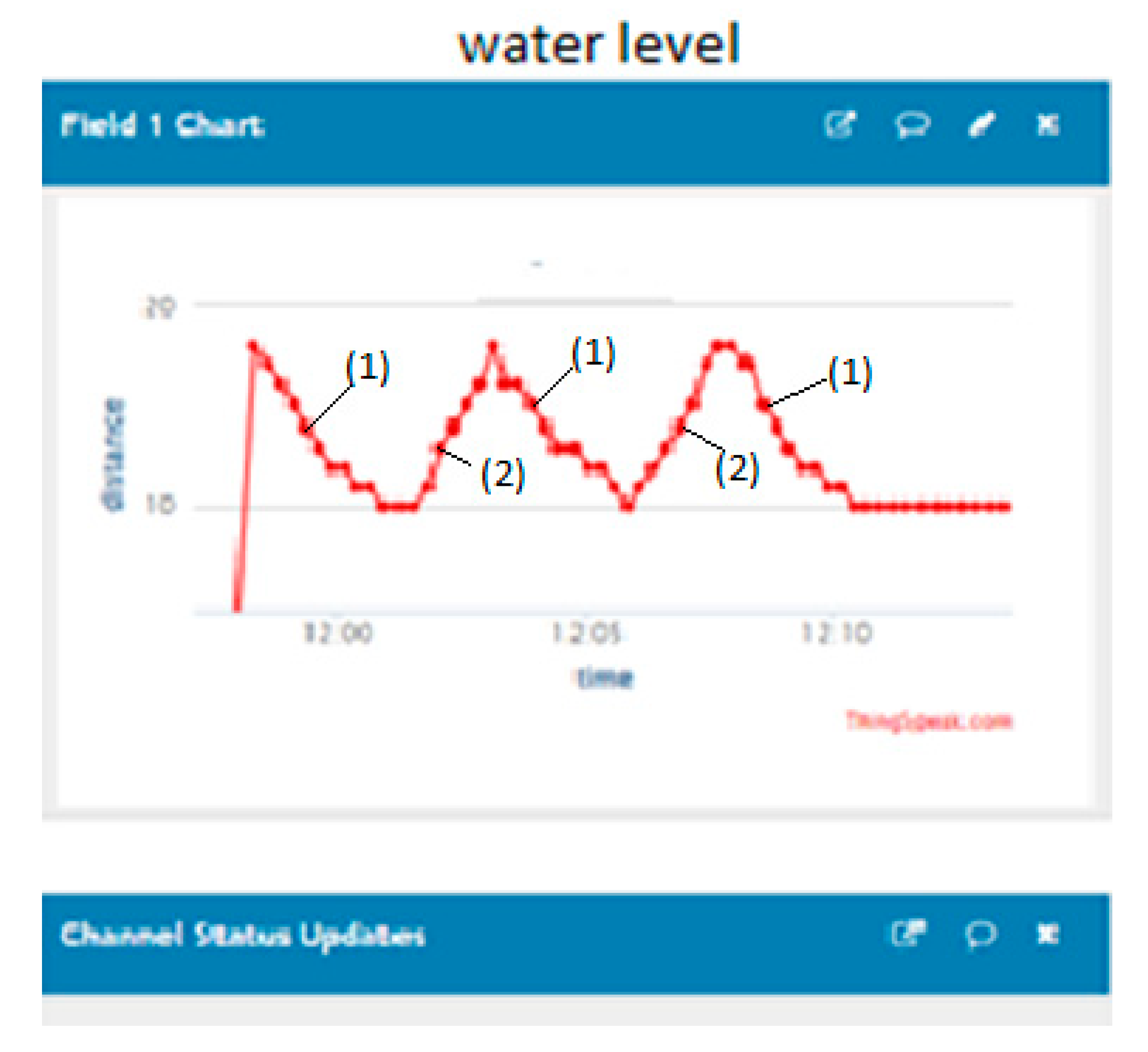
Experimental trials have been performed for three scenarios. In the first scenario the data being sent by the ESP 8266 to the ThingSpeak platform have been recorded at successive filling and emptying operations within the limits established through the program Hmax = 18 cm and Hmin = 10 cm. The distance Hmax corresponds to the minimum level of water in the tank and the distance Hmin corresponds to the maximum water level in the tank. The water level will be minimum when the ultrasonic sensor measures a distance higher than 18 cm and pump 1 startup will be automatically commanded for supplying the tank with water. The water level will be maximum when the ultrasonic sensor measures a distance lower than 10 cm and the pump 1 that supplies the tank will be automatically stopped. At the same time the startup of the pump 2 may be remotely commanded by means of the mobile phone for emptying the tank. The level variation recorded by the circuit ESP 8266 will increase from 10 cm to 18 cm. When the water level reaches the minimum value (i. e. the distance measured from the sensor HC-S04 to the floater will be higher than 18 cm) the pump 2 for emptying the tank will be stopped through the command from the mobile phone and, automatically, the pump 1 for water supplying the tank will start. This cycle may be repeated for an infinite number of times.
Figure 6 represents in real time the variation diagrams of the water level for filling (1) and emptying the tank (2) obtained on the channel 1 of the ThingSpeak platform.
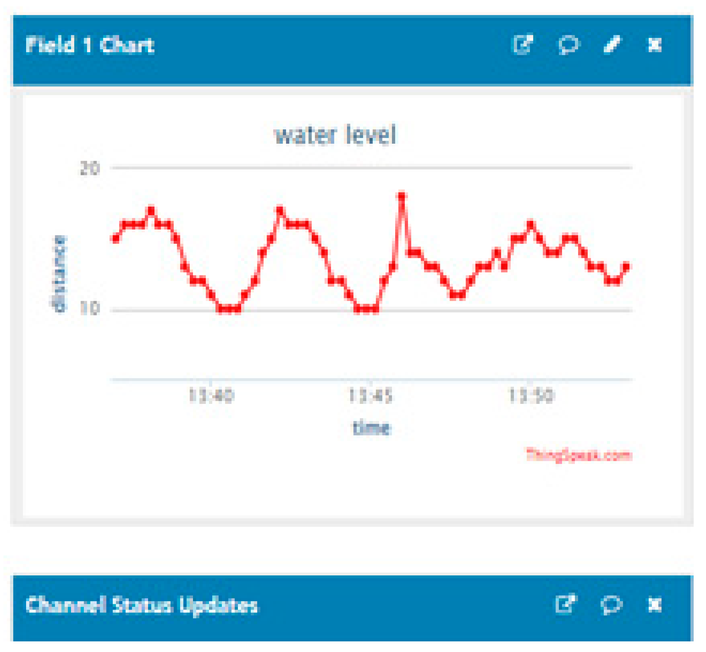
In the second scenario, after two filling and two emptying operations, the emptying pump 2 has been started for a short time before the water level in the tank reaches the maximum value. In this manner, both pumps will be running as shown at
Figure 7.
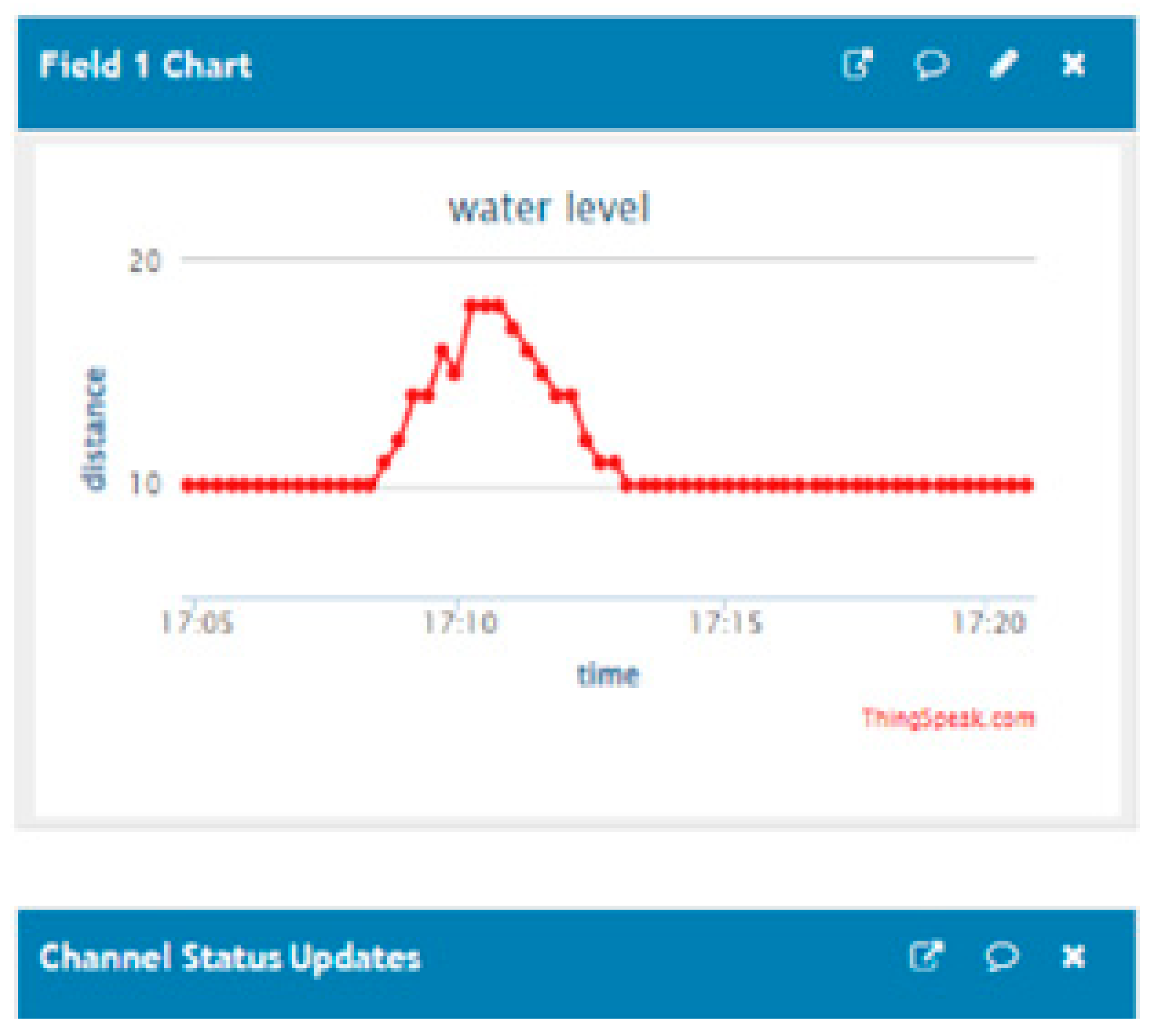
The water level in the tank will be between the two limits settled through the program. In the third scenario it will be verified whether the maximum level of water is provided when there is only one emptying operation for supplying one consumer,
Figure 8.
4. Conclusions
This work is presenting a prototype for controlling and monitoring the water level in a tank, equipped with the development boards Arduino Uno, NodeMCU ESP8266 and the ultrasonic sensor HC-SR04. For the water management in the tank three applications have been issued: - Control of the water level in the tank; - Monitoring the water level in the tank; - Command through the mobile phone of the water supply pump to the consumers. For the three applications the author has elaborated programs in the programming environment Arduino IDE. For controlling the water level in the tank, the author has developed an algorithm that has been implemented and validated on the experimental stand of the Electrical Machinery and Drives laboratory of the Engineering Faculty – Bacau University. Based on the experimental outcomes it has been found out that this prototype for controlling and monitoring the water level in a tank assures the performances required through the designing stage. For monitoring the development board NodeMCU ESP8266 has been used that takes over the information from the ultrasonic sensor HC-SR04 and sends it through Wi-Fi to the platform ThingSpeak. By having this online information on the water level in the tank, the operator has the opportunity to program the water supply for the domestic consumers or irrigation systems in function of the existing water reserve. For the control through the mobile phone of the water supply pump to the consumers another development board Arduino Uno has been used, as well as the bluetooth sensor HC-06. The main advantage of this prototype consists of the fact that it provides the control at an accuracy of 0,3 cm for the water level in the tank, at a low price of the equipment being used. This prototype has also a universal character. The prototype does not require any hardware modification in case of usage for other tanks, but software modifications only of the parameters to be controlled. The disadvantage of this prototype consists of the fact that a powerful Wi-Fi signal is necessary for data transmission from the development board NodeMCU ESP8266 to the ThingSpeak platform. The references being quoted in this work did not present any prototype alike for the water level management in a tank. In perspective, the water level control and monitoring system in a tank can be improved by using several industrial level encoders and regulators.
References
- Available online: https://www.thehealthyjournal.com/faq/is-3-of-earths-water-freshwater.
- Amrit Kumar Panigrahi, Chandan Kumar Singh, Diwesh Kumar, Nemisha Hota Tank Water Level Indicator & Controller Using Arduino. International Journal of Advanced Research in Electrical, Electronics and Instrumentation Engineering 2017, 6,, 1348–1354.
- Pandey, A.; Andhale, G.; Sonawane, A.; Amrutkar, A.; Andhare, T. AUTOMATIC WATER LEVEL INDICATOR AND CONTROLLER USING ARDUINO. International Research Journal of Engineering and Technology (IRJET) 2020, 7, 5342–5346. [Google Scholar]
- Rehman, A. U.; Hussain, M.; Idress, M.; Munawar, A.; Attique, M.; Anwar, F.; Ahmad, M. E-cultivation using the IoT with Adafruit Cloud. International Journal of Advanced and Applied Sciences 2020, 7, 75–82. [Google Scholar]
- Khiareddine, A.; Salah, C. B.; Mimouni, M. F. Control water level of a photovoltaic pumping system. 2013 International Conference on Control, Decision and Information Technologies (CoDIT); IEEE; pp. 435–440. [CrossRef]
- Ammar, A.; Hamraoui, K.; Belguellaoui, M.; Kheldoun, A. Perfor- mance Enhancement of Photovoltaic Water Pumping System Based on BLDC Motor under Partial Shading Condition. Eng. Proc. 2022, 14, 22. [Google Scholar] [CrossRef]
- Navya, M.S.; Nirosha, G.J.; Sangeetha, V. AUTOMATIC WATER CONTROLLER. International Advanced Research Journal in Science, Engineering and Technology 2021, 8. [Google Scholar]
- Eltaieb, A.A.M.; Min, Z.J. Automatic Water Level Control System. International Journal of Science and Research (IJSR) 2015, 4, 1505–1509. [Google Scholar]
- Big-Alabo, A.; Isaac, C. Automatic Water Level Control System Using Discretized Components. J. Appl. Sci. Environ. Manage. 2020, 24, 1781–1785. [Google Scholar] [CrossRef]
- Sarode, S.; Kalwe, C.; Gedam, A.; Bhaisare, N.; Bagal, S. A Review on Arduino Based Automatic Water Pump Level Adjustment and Monitoring System. International Journal for Research in Applied Science & Engineering Technology (IJRASET) 2022, 10, 813–816. [Google Scholar]
- Mallikarjun, H.; Nagaraj, S. N.; Shrikanth, B. J.; Ali, A. S.; Pramod, G. Flexible Automatic Water Level Controller and Indicator. World Journal of Technology, Engineering and Research 2018, 3, 359–366. [Google Scholar]
- Selvan, M.; Roy, A.; Singh, K. P.; Kumar, A. AUTOMATIC WATER LEVEL INDICATOR USING ULTRASONIC SENSOR AND GSM MODULE. IJARIIE 2018, 4, 261–269. [Google Scholar]
- Bruno, F.; De Marchis, M.; Milici, B.; Saccone, D.; Traina, F. A Pressure Monitoring System forWater Distribution Networks Based on Arduino Microcontroller. Water 2021, 13, 2321. [Google Scholar] [CrossRef]
- Hilal, Y. Y.; Khessro, M. K.; van Dam, J.; Mahdi, K. AutomaticWater Control System and Environment Sensors in a Greenhouse. Water 2022, 14, 1166. [Google Scholar] [CrossRef]
- Siregar, C. A.; Mulyadi, D.; Biantoro, A. W.; Sismoro, H.; Irawati, Y. Automation and Control System on Water Level of Reservoir based on Microcontroller and Blynk; IEEE, 2020; pp. 1–4. [Google Scholar]
- Mary, X. A.; Rose, L.; Rajasekaran, K. Continuous and remote monitoring of ground water level measurement in a well. Int. J. Water 2018, 12, 356–369. [Google Scholar] [CrossRef]
- Liyanage, D. K.; Chathuranga, I.; Mori, B. A.; Thilakarathna, M. S. A Simple, Semi-Automated, Gravimetric Method to Simulate Drought Stress on Plants. Agronomy 2022, 12, 349. [Google Scholar] [CrossRef]
- Chinaeke-Ogbuka, I.; Ajibo, A.; Ogbuka, C. A Microcontroller-Based Water Level Indicator using Radio Frequency (RF) Technology and Ultrasonic Sensor. International Journal of Scientific & Engineering Research 2019, 10, 775–779. [Google Scholar]
- Pasika, S.; Gandla, S. T. Smart water quality monitoring system with cost-effective using IoT. Heliyon 2020, 6. [Google Scholar] [CrossRef]
- García, L.; Garcia-Sanchez, A. J.; Asorey-Cacheda, R.; Garcia-Haro, J.; Zúñiga-Cañón, C. L. Smart Air Quality Monitoring IoT-Based Infrastructure for Industrial Environments. Sensors 2022, 22, 9221. [Google Scholar] [CrossRef] [PubMed]
- Khandebharad, R.; Garad, S.; Garad, A.; Moholkar, S.; Daphale, D. IOT-Based Monitoring and Control System for Greenhouses. International Journal of Advanced Research in Science, Communication and Technology (IJARSCT) 2023, 3. [Google Scholar] [CrossRef]
- Wan, Z.; Song, Y.; Cao, Z. Environment Dynamic Monitoring and Remote Control of Greenhouse with ESP8266 NodeMCU. Information Technology, Networking, Electronic and Automation Control Conference (ITNEC 2019); pp. 377–382.
- Available online: https://www.wardsci.com/store/product/23748699/arduino-uno-development-board.
- Ismailov, A. S.; Jo‘Rayev, Z. B. Study of arduino microcontroller board. Science and Education 2022, 3, 172–179. [Google Scholar]
- Louis, L. WORKING PRINCIPLE OF ARDUINO AND USING IT AS A TOOL FOR STUDY AND RESEARCH. International Journal of Control, Automation, Communication and Systems (IJCACS) 2016, 1, 21–29. [Google Scholar] [CrossRef]
- Sulistiyo, E.; Wibawa, S. C.; Meduril, N. R. H.; Ngelambong, A. Design and Verification of Arduino Uno-Based Analog and Digital Trainers as Student Worksheets on Microprocessor and Microcontroller Programming Technique. International Joint Conference on Science and Engineering 2021 (IJCSE 2021); pp. 77–81.
- Abdulkhaleq, N. I.; Hasan, I. J.; Salih, N. A. J. Investigating the resolution ability of the HC-SRO4 ultrasonic sensor. Materials Science and Engineering 2020, 012043. [Google Scholar] [CrossRef]
- Al Tahtawi, A. R. Kalman Filter Algorithm Design for HC-SR04 Ultrasonic Sensor Data Acquisition System. IJITEE 2018, 2, 15–19. [Google Scholar] [CrossRef]
- Available online: https://electropeak.com/learn/nodemcu-esp8266-on-arduino-ide/.
- Adriansyah, A.; Dani, A. W. Design of Smart Home System Using Arduino. Mathematical Statistician and Engineering Applications 2022, 71, 186–191. [Google Scholar] [CrossRef]
- Sri Lakshmi, T.; Sowmya, T.; Pushpa, P. AUTOMATIC BLUETOOTH BASED IRRIGATION SYSTEM. Journal of Engineering Sciences 2020, 11, 33–35. [Google Scholar]
|
Disclaimer/Publisher’s Note: The statements, opinions and data contained in all publications are solely those of the individual author(s) and contributor(s) and not of MDPI and/or the editor(s). MDPI and/or the editor(s) disclaim responsibility for any injury to people or property resulting from any ideas, methods, instructions or products referred to in the content. |
© 2023 by the authors. Licensee MDPI, Basel, Switzerland. This article is an open access article distributed under the terms and conditions of the Creative Commons Attribution (CC BY) license (http://creativecommons.org/licenses/by/4.0/).
