Preprint
Article

Determination Method of Kinetic Parameters of Strength Recovery in Self-Healing Ceramic Composites

Altmetrics

Downloads

136

Views

58

Comments

0

A peer-reviewed article of this preprint also exists.

Submitted:

24 April 2023

Posted:

24 April 2023

You are already at the latest version

Alerts
Abstract
Self-healing ceramic composites are promising smart materials for high-temperature applications. To better understand their behaviors under service conditions, numerous studies have been performed both experimentally and numerically, and kinetics parameters such as activation energy and frequency factor are reported to be indispensable for investigating healing phenomena. Here, we propose a method for determining the kinetic parameters of self-healing ceramic composites based on the oxidation kinetics model of strength recovery. These parameters are determined by an optimization method using experimental strength recovery data under various healing temperatures and times and microstructural features on the fractured surfaces. Alumina and mullite matrix-based self-healing ceramic composites, such as Al2O3/SiC, Al2O3/TiC, Al2O3/Ti2AlC (MAX phase), and mullite/SiC, were selected as target materials. The theoretical strength recovery behaviors of the cracked specimens obtained from the determined kinetic parameters were compared with the experimental results. The determined parameters are within the previously reported range, and the predicted strength recovery behaviors are reasonably agreed with the experimental values. The proposed method can also be applied to other self-healing ceramics with matrices reinforced with different healing agents to evaluate oxidation rate, crack healing rate, and theoretical strength recovery behaviors for designing self-healing materials used in high temperature applications. Furthermore, the healing ability of composites can be fairly discussed regardless of the type of strength recovery test.
Keywords: 
Subject: Engineering  -   Mechanical Engineering

1. Introduction

Self-healing ceramics are expected to be used in high-temperature structural applications with high-levels of safety requirement owing to their unique ability of autonomic healing of surface cracks and their outstanding mechanical properties as a ceramic such as lightness, high thermal resistance, corrosion resistance, wear resistance, and high fracture strength. Therefore, it has attracted more attention of materials researchers to analyze mechanical behaviors during service conditions in detail for developing outstanding candidates of self-healing ceramics used in sophisticated applications [1,2,3,4,5,6,7,8]. Under such circumstances, experimental and numerical investigations have been conducted to analyze the self-healing capability of ceramics and their effects on their mechanical properties.
To the best of author’s knowledge, the earliest work related to the so-called ’healing‘ mechanism reported by Heuer et al. [9] in 1966 was based on confirmation of the effect of annealing on the strength of alumina crystals. Lange et al. [10] analyzed the effect of annealing on crack healing of thermally shocked ZnO and used the term ‘crack-healing’ in 1970. Pioneering work realizing to ‘autonomous’ and ‘full’ recovery of strength has been reported by Ando et al in 1995 [11], in which the oxidation-induced self-healing of crack were proposed in mullite/SiC ceramic composites, subsequently, reported in Si3N4/SiC ceramic composites in 1998 [12] and 1999 [13], respectively. Latterly, inspired by natural self-healing in human body such as bones, extensive studies were performed on different matrix and healing agent (HA)-based composites such as Al2O3/SiC [14,15,16,17], Al2O3/TiC [18], Al2O3/TiC/TiB2 [19], Al2O3 with Ni-based nano composites [20,21,22], Al2O3/SiCw [23], Si3N4/SiC particle [24], Si3N4/SiCw [25], SiC/SiC ceramic [26], SiN/SiC [27], mullite/SiC [28], mullite/SiC/Y2O3 [29], ZrO2/SiC/TiO2 [30], and MAX-phases ceramics [31,32,33,34,35] to demonstrate self-crack healing ability and strength recovery behaviors by adopting different strength testing methods. The self-crack-healing ability of high-temperature structural materials under service conditions is an emerging invention to ensure mechanical reliability and integrity for practical applications. Experimental investigations in the aforementioned studies were conducted through variation of the healing temperature, time, environment (N2, Ar, vacuum, O2-N2 mixed), oxygen partial pressure, volume fraction of HAs (15–30%), particle size of HAs (micro, nano), and indented crack size (40–1200   μ m ); by a crack indentation method (Vickers, Knoop); by healing under no stress and applied stress condition, and via a testing method of healed strength (three-point, four-point bending). However, experimental investigations are expensive, time-consuming, and require sophisticated experimental setups for the analysis of self-healing ceramic materials before and after healing.
Meanwhile, novel numerical analysis schemes need to be developed to analyze the behaviors of self-healing ceramics, considering real conditions in application fields to ensure reliability, mechanical integrity, and safety margins. Numerical analysis using finite element modeling is a suitable option for the frequent study of self-healing ceramic materials. Continuum damage-healing constitutive models used to analyze the damage formation and healing capability of different self-healing materials were developed at different times. Under these circumstances, Ozaki et al. [36] successfully developed constitutive equations based on the isotropic damage model [37] and applied them to alumina matrix–based ceramics within the framework of finite element modeling. Subsequently, they developed an oxidation kinetics-based crack healing model and applied it to alumina/SiC based self-healing composites [38]. More importantly, Osada et al. [39] developed a universal kinetics model for the strength recovery of self-healing ceramics. In this model, microstructural information, crack geometries, volume fraction of HAs, crack propagation direction, and kinetic parameters of HA oxidation were considered. They also proposed a tip-to-mouth crack-gap filling model that can be applied for different matrix-based composites by incorporating different HAs. However, no framework is available to determine the kinetic parameters such as the activation energy (AE) and frequency factor (FF) of HA-oxidation in self-healing ceramic composites. To better understand the self-healing capability under service conditions, the determination of AE and FF is indispensable.
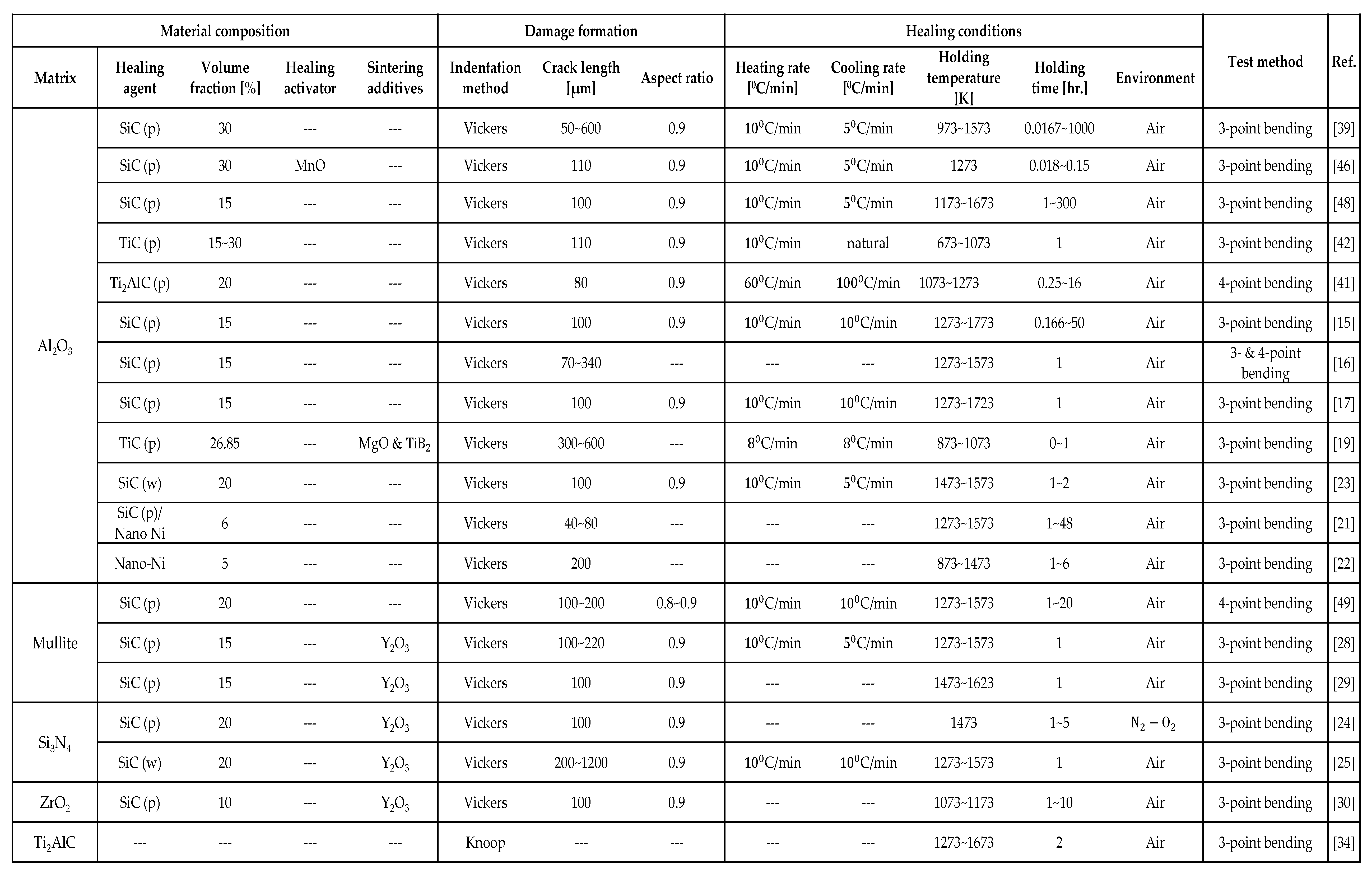
Furthermore, once the AE and FF are determined, they can be applied to finite element analysis as parameters of the damage-healing constitutive model [38]. Furthermore, full experimental dataset of temperature- and time-dependence of minimum healing time for full strength recovery and strength recovery rate required for comparison in healing ability of above healing ceramics was limited in the previous studies, since different researchers tested different materials under various experimental conditions as shown in Table 1. If the framework determining those kinetic parameters from limited experimental data is proposed, it could be very useful for the new material design.
In this study, we propose a novel method to simultaneously determine these kinetic parameters by optimizing a universal kinetics model using experimental data on strength recovery behaviors. This method can predict a suitable range of kinetic parameters for each experimental set of composites by performing multiple analyses of the healing conditions. In addition, the theoretical strength recovery behaviors of several self-healing ceramic composites were predicted using these kinetic parameters, and the effectiveness of the optimized kinetic parameters was confirmed through comparison with previously reported experiments. This study primarily focuses on determining the AE and FF, and the characteristics of the oxidation rate, healing rate, and minimum time required for complete healing of different HAs incorporated with alumina and mullite matrices are discussed. The oxidation and healing rate of HAs with the matrix, which are necessary for the selection of suitable candidates for applications, can be predicted using these parameters.

2. Universal kinetic model of strength recovery

This section describes in detail the volume-gain kinetics model and tip-to-mouth crack-gap filling models for self-healing ceramic materials [39] underlying the parameter determination method.

2.1. Volume-gain kinetics model

The healing mechanisms of self-healing ceramics are explained by an oxidation kinetics-based healing model [39]. This model could be applied to various HAs-based composites. Volume gains due to oxidation-induced reaction leads to weight gain, and the schematic illustration of this phenomenon is presented in Figure 1.
The isothermal weight gain formula can be expressed as a function of healing temperature and time, oxygen partial pressure, kinetics parameters, and features of the fractured surface and HAs. The general formulation of the isothermal weight gain is as follows:
w = k p t H 1 n ,
where k p is the oxidation rate constant, t H is the holding healing time, and n signifies the rate-controlling oxidation mechanism. For oxidation of SiC as HA, n = 2 can be adopted [39]. Meanwhile, n = 2 was also considered for the TiC-HA oxidation. Furthermore, n = 3 is adopted for the oxidation of Ti2AlC MAX-phase healing agent in alumina matrix [35]. The rate constant k p can be formulated by considering the effect of the oxygen partial pressure as follows:
k p = k p o   exp   Q o x R T H P O 2 P O 2 0 m ,
where Q o x and k p o are AE and FF of HA-oxidation, respectively, for the oxidation of HAs; TH is the healing temperature; P O 2 is the oxygen partial pressure; P O 2 0 is the standard oxygen partial pressure; R is the gas constant; m = 0.835 [39] is a temperature-independent constant experimentally determined for the healing reaction in the N2-O2 mixed gas. Hence, the weight gain for HA-oxidations can be described as
w = k p o e x p Q o x R T h P O 2 P O 2 0 m t H 1 n ,    
Furthermore, the volume gain V h during the isothermal oxidation reaction can be converted from the weight gain as follows:
V h = A 0 ρ w = 2 A f v f e ρ k p o e x p Q o x R T h P O 2 P O 2 0 m t H 1 n ,
where A 0 (reactive area fraction) = 2A f v f e , and A is the area of one side of the fractured surfaces. ρ is the weight gain per unit volume gain for HA oxidation. The volume gain owing to the self-healing reaction depends on the free surface of the unreacted HAs on the fractured surfaces. The volume fraction f v of HAs and the crack propagation path determine the actual reactive area fraction of HAs. In general, the volume fraction of HAs, f v , ranging from 0.15 to 0.30 has been used for complete healing of cracks based on a number of experimental analysis reported in [14,15,28,40]. The effective reactive area ratio, f e is considered to be 0.5 when the crack propagates along the interface of the matrix–HAs, as the HAs are located on one side of the fractured surface, as shown in Figure 1. In this study, f e is used as 0.5 for SiC-HAs oxidation with alumina and mullite-based matrix. Furthermore, f e = 1.0 when the crack propagates through the HAs, which is considered for monolithic ceramics mainly consisting of HAs, such as SiC and Ti2AlC. Notably, f e = 0.5 and f e = 1.0 are assumed in the case of TiC and Ti2AlC oxidation respectively, as detected from the scanning electron microscope (SEM) images after cracking, which implies that crack propagate along the interface of the matrix–HAs and through the HAs, respectively [41,42]. Here, the crack propagation path could mainly depend on the differences in fracture strength, toughness, and stiffness between the matrix and HAs, [39].
ρ is the weight gain per unit volume gain for HAs oxidation. For SiC oxidation,
ρ = M S i O 2 M S i C M S i O 2 ρ S i O 2 M S i C ρ S i C ,
where MSiC, MSiO2, ρ S i C , and ρ S i O 2 are the molar mass and molar density of SiC and SiO2, respectively. Furthermore, ρ can also be calculated in the similar manner for TiC and Ti2AlC oxidation by the following general formula:
ρ = i = 1 n i M H P i M H A i = 1 n i M H P i ρ H P i M H A ρ H A ,
where M H P i a n d ρ H P i are the molar mass and molar density of ith healing product (HP), respectively, and M H A a n d   ρ H A are the molar mass and molar density of HAs, respectively. In this study, ρ = 1.4908×10³, 2.9760×10³, and 4.7133×10³ were used for SiC-, TiC- and Ti2AlC-HAs oxidation.
Finally, the volume-gain rate from the oxidation kinetics model is expressed as follows:
V h ˙ = 1 n V h n 1 2 A f v f e ρ n k p  
The initial value of volume gain V h 0 in the numerical analysis is expressed by the following equation:
V h 0 = 2 A f v f e ρ n k p t 0 1 n .
Here, t 0 is the initial time increment. Equations (4), (7), and (8) are useful for determining the healing parameters of different HAs under isothermal and non-isothermal conditions.

2.2. Tip-to-mouth crack-gap filling model

Various experimental studies have been conducted on the self-healing of cracks induced by the Vickers indentation method. Many researchers have revealed that these indented cracks are completely or partially healed with different healing temperatures, times, and other parameters [15,17,23]. The experimental strength of the cracked specimens is recovered through crack-gap filling by the oxidation products from the HAs incorporated within the matrix. Note that crack-gap filling can be modeled theoretically using the tip-to-mouth crack-gap filling model and bridging model [39]. In this study, the tip-to-mouth crack-gap filling model was adopted.
The crack-gap filling ratio R f is an important parameter that determines the level of strength recovery during self-healing and is expressed as follows:
R f = V h V g
Here, V g is the crack-gap volume and is expressed as follows:
V g = π δ m a x 6 ( c 2 a c + 2 a 2 ) ,
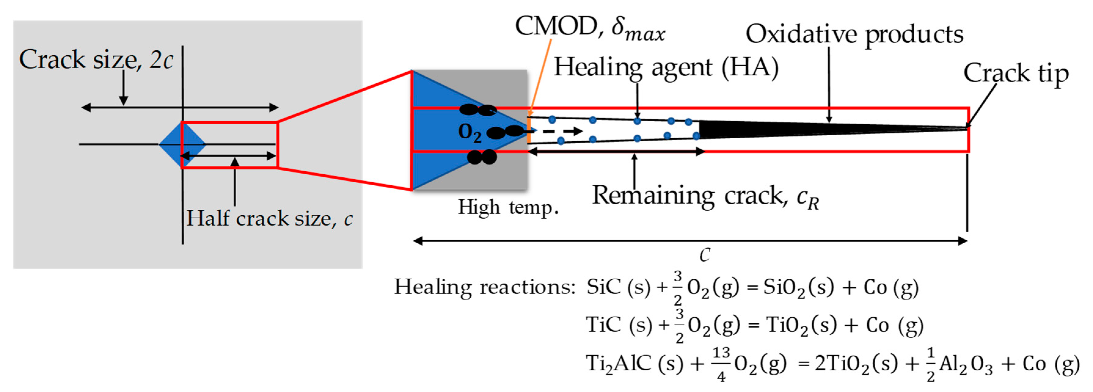
where c is the half-crack length, as shown in Figure 2; a is the crack depth of a median/radial crack introduced by Vickers indentation and is defined by the aspect ratio a / c   = 0.9. δ m a x is the maximum crack mouth opening displacement (CMOD), which is related to the initial CMOD, and it decreases significantly due to annealing. In this study, we adopt the following empirical equations applicable for alumina matrix–based composites [39], to evaluate δ m a x :
δ m a x = δ m a x 0 exp T H T b   q ,
where δ m a x 0 is the initial CMOD before annealing. T b   = 1523 K and q = 9 are the empirical fitting parameters. The empirical relation between δ m a x 0 and half-crack size c is expressed as follows:
δ m a x 0 = 4.06 c
= 4.06 c.
The total crack-gap volume after annealing for a specific crack geometry induced by Vickers indentation can be estimated using Equations (10)–(12). Hence, the filling ratio R f for SiC and TiC HA oxidation when incorporated within alumina matrix–based composites becomes
R f = 2 A f v f e ρ k p o e x p Q o x R T h P O 2 P O 2 0 m t H π δ m a x 6 ( c 2 a c + 2 a 2 ) ,
where one side area of the fractured surface is expressed as A = π 2 ( c 2 a 2 ). As assumed, the oxidation products start filling the crack from the crack tip point to the mouth in the tip-to-mouth filling model. Furthermore, the crack opening displacement increases linearly from the tip to the mouth, as shown in Figure 2. Thus, the crack size evolution in this model is given as follows:
c R = c   ( 1 - R f ) .
It is noteworthy that the strength recovery rate is strongly dependent on the remaining crack size c R .The theoretical strength recovery rate can be estimated based on nonlinear fracture mechanics [23,43,44] as a function of the remaining crack size, fracture toughness, and smooth specimen strength:
σ f = c o s 1 8 c R F 2 σ 0 2 π K I C 2 + 8 c R F 2 σ 0 2 2 σ 0 π ,
where F is a geometric factor that can be estimated using the Newman–Raju equation [45]. For simplicity in calculation, we used the crack size evolution as calculated by Equation (14) and geometric factor estimated by Newman–Raju equation. σ 0 is the strength of smooth specimen. KIC is the mode I fracture toughness of the composite, which can be expressed as follows:
K I C = K + K r e s ,
where K is the stress intensity factor at the crack-tip caused by the external applied stress and K r e s is the stress intensity factor at the crack tip caused by the internal tensile residual stress near the indent. According to Osada et al. [39], K r e s can be approximated using the following empirical equation:
K r e s = 0.4   K   exp T H T c p ,
where T c = 1423 K and p = 11 are the fitting parameters used in this model.
The stress intensity factor due to the residual stress is relaxed significantly by high-temperature healing, which has been followed in this model to predict the theoretical strength recovery behaviors. The remaining crack size c R in the tip-to-mouth filling model is the only indicator of cracked strength recovery in Equation (15). R f < 1 owing to the low temperature or short healing period corresponds to a partial crack healing state. In contrast, w h e n R f = 1 corresponding to a high temperature or long period of healing, then c R   = 0, signifying that complete crack healing leads to full strength recovery at the same level as the strength σ 0 of the smooth specimen.

3. Parameter determination method

3.1. Target composites

In this study, alumina matrix reinforced with SiC, TiC, and T i 2 AlC and mullite reinforced with SiC were used. In these composites, the volume fraction of HAs was designed to be 15–30%, according to the requirement of healing kinetics to achieve strength recovery. The alumina reinforced with 15 and 30 vol.% SiC was referred to as ‘AS15P’ and ‘AS30P’ and mullite reinforced with 20 vol.% SiC was referred to as ‘MS20P’ respectively, and they were treated as SiC-HA-based composites to investigate their oxidation and healing capability.
The alumina reinforced with 15 and 30 vol.% TiC belongs to TiC-HA-based composites that are one of the emerging self-healing ceramic candidates, as they can be used in applications with comparatively lower healing temperatures. We refer to these composites as ‘AT15P’ and ‘AT30P’, respectively. In addition, alumina matrix reinforced with a MAX-phase HA ( T i 2 AlC) is another candidate for autonomous crack healing in high-temperature applications. Notably, MAX-phase ceramics act as both a matrix and healing agent owing to their physio-chemical natures [41]. Alumina reinforced with 20 vol.% T i 2 AlC, referred to as ‘AT20MAX’ belongs to MAX-phase HA-based composite.
The parameter determination method utilizes the strength recovery behaviors corresponding to healing conditions, micro-structural information, crack geometries, and other experimental data. The basic information on the target composites is summarized in Table 1. The experimental healing process comprises of three steps: heating, holding, and cooling. Although the healing temperature and time in the holding stage are crucial for healing and cracked strength recovery, the heating and cooling stages cannot be ignored in the healing behaviors. These stages are strongly reflected stringently to the parameter determination and theoretical strength recovery calculations.

3.2. Parameter optimization

The determination of the kinetic parameters of AE and FF of HAs-oxidation based on optimization is the most significant aspect of this study. The AE and FF are optimized by comparing the experimental and theoretical strength recoveries corresponding to the healing temperature, time, and other features. Here, the theoretical strength recovery calculated using Equation (15) strongly depends on the remaining crack size obtained using the tip-to-mouth crack-gap filling model. Therefore, micro-structural features such as crack geometry and its aspect ratio, size, and vol.% fraction of HAs are used to calculate the theoretical strength recovery.
In the parameter optimization, thousand combinations of AE and FF were automatically varied within the prescribed range with a small interval in the theoretical calculations to reduce the absolute error (error between the experimental and theoretical strength) while keeping the other parameters fixed. Here, the lowest absolute error point between the theoretical and experimental strengths was explored using Equations (18) and (19). In general, the mean relative error and least squares method are commonly used to optimize different scientific parameters by calculating the absolute error.
Firstly, the mean relative error in this study is calculated as follows:
m e a n r e l a t i v e e r r o r = 1 N i = 1 n n j = 1 m m σ exp ( i j ) σ t h ( i j ) σ exp ( i j ) ,
where i = 1 to nn represents different healing temperatures, and j = 1 to mm represents different healing times. σ e x p ( i j ) is the experimental strength corresponding to the healing temperature and time, whereas σ t h ( i j ) is the theoretical strength corresponding to the experimental conditions. N is the total number of healed strength points considered in the optimization. The mean relative error values were plotted in the global and local error curves to explore the optimized points of AE and FF. The proposed method provides the value of AE and FF corresponding to the lowest error is considered the best combination of AE and FF for a target self-healing ceramic composite.
Furthermore, the least squares method was applied to calculate the error to optimize AE and FF. The mean squared error is expressed as follows:
m e a n s q u a r e d e r r o r = 1 N i = 1 n n j = 1 m m σ exp ( i j ) σ t h ( i j ) 2 .
The relative error method and least squares method based on Equations (18) and (19) can be used to explore AE and FF for every ceramic composite, and they output almost the same AE and FF. Therefore, this study reports only the AE and FF values obtained via the relative error method, which are used to calculate the theoretical strength recovery, as shown in the next section. A suitable range of AE and FF values for all composites can be obtained by considering multiple experimental healed strength data points, including completely healed and partially healed strengths.

4. Results

The theoretical strength recovery behaviors shown in this section for all composites used the optimized values of AE and FF. It should be noted that the experimentally healed strength data above the bold blue line in the graphs were not considered in the optimization because the fracture started from outside the healed part in the case of super healing.

4.1. SiC–HA-based alumina and mullite composites

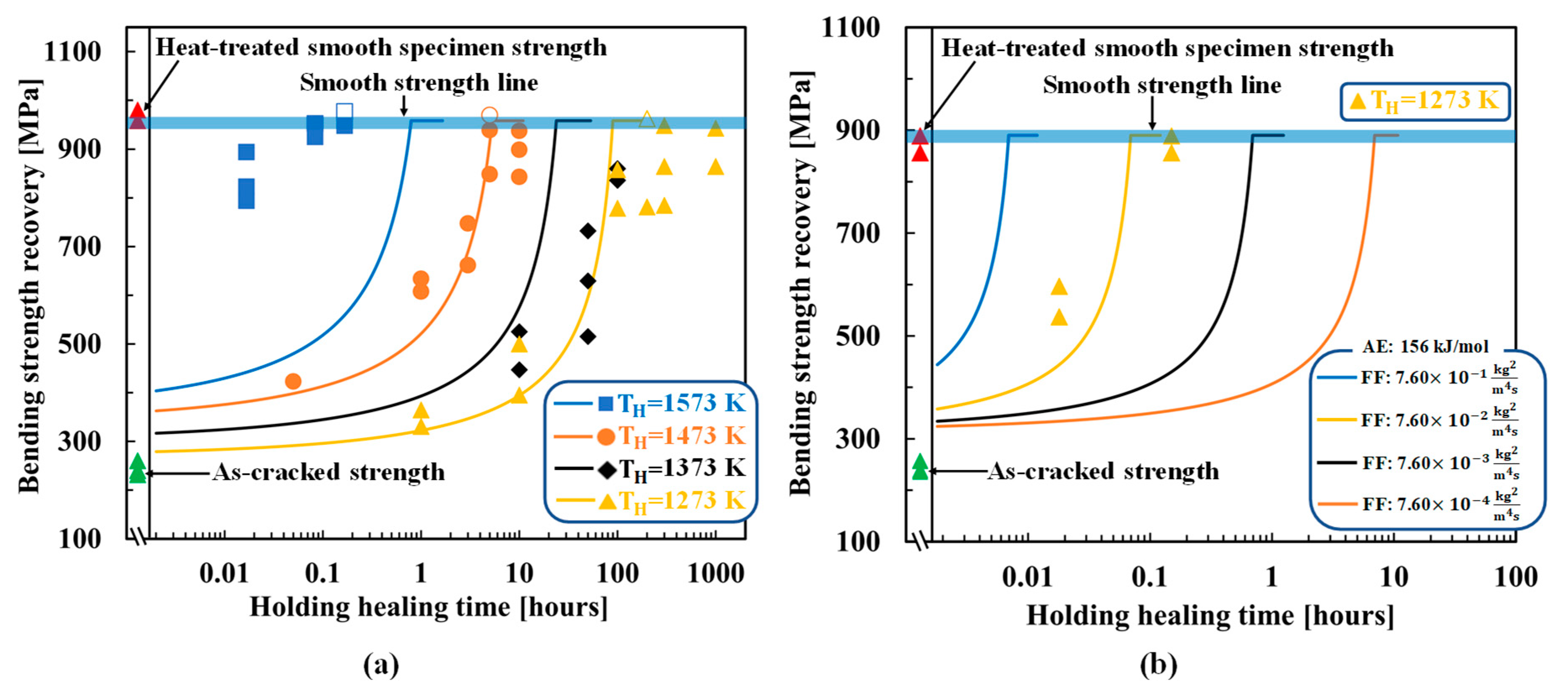
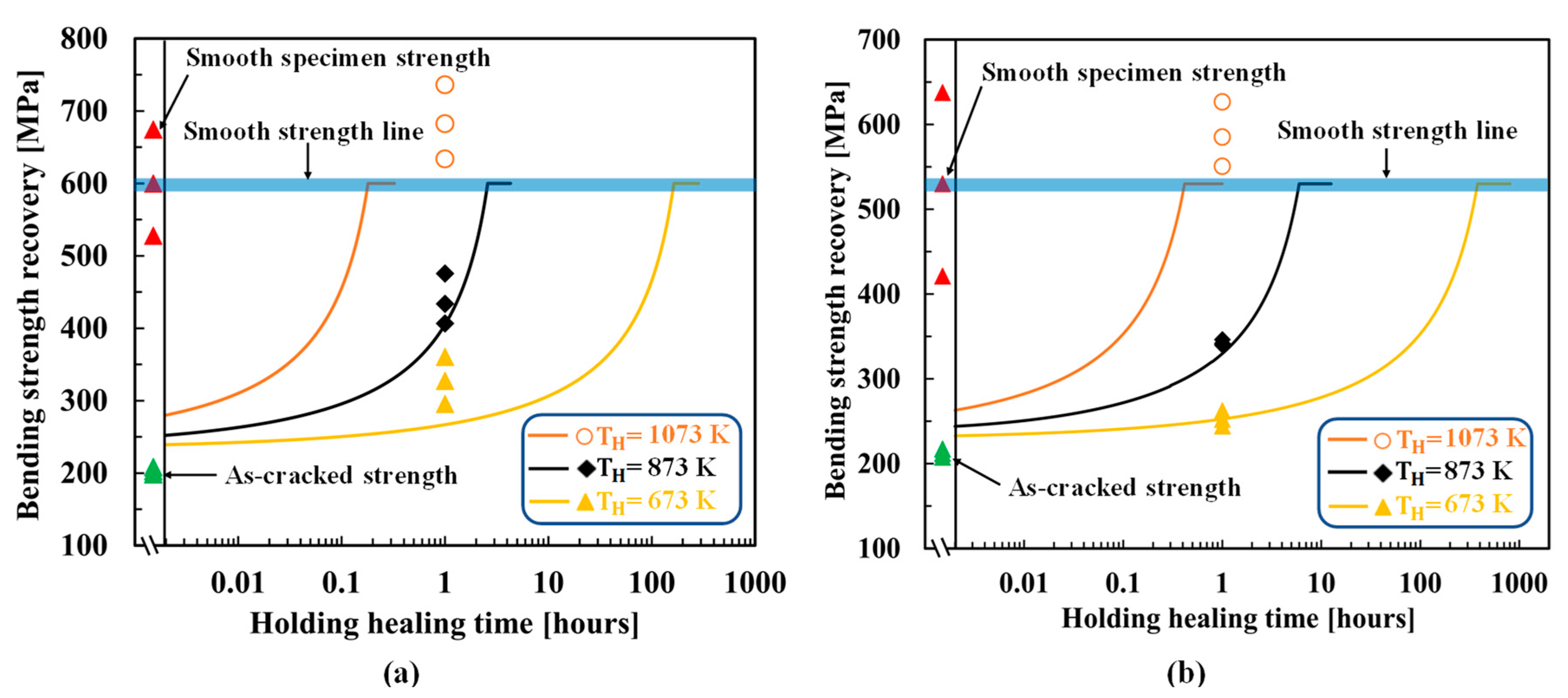
Figure 3a compares the experimental and theoretical (Equation (15)) results for the healing temperature- and time-dependent strength recovery behaviors of AS30P. The figure also shows the experimental as-cracked strength and heat-treated smooth specimen strength. In AS30P, the optimized AE and FF are 136 kJ/mol and 8.90 × 10 6 k g 2 m 4 s , respectively. Because the tip-to-mouth filling model corresponds to the lower strength in healed specimen [39], the strength of smooth specimen represented by blue bold lines is adopted for σ 0 . Theoretical strength calculated from Equation (15) is gradually increased from as-cracked strength with the holding healing time and reaches to strength of smooth specimen, σ 0 , when remaining crack length c R calculated from Equation (14) becomes zero ( R f = 1 ). The holding healing time at which theoretical strength equals to σ 0 is termed as theoretical minimum time for complete healing even after this time, theoretical strength lines (colored smooth lines) remains constant as shown in the figures. The theoretical strength recovery behaviors are in reasonable agreement with the experimental results, except at the high temperature of 1573 K. The error at high temperatures is due to the sensitivity of the initial CMOD to the crack-gap volume calculation in the tip-to-mouth filling model. In addition, the existence of small defects and internal pores around the Vickers cracks was not considered in the theoretical analysis, which is another reason for the difference between the experimental and theoretical cracked-strengths.
Figure 3b shows the optimized results for AS30P with the healing activator. In this composite, a healing activator, 0.2 vol.% MnO is added along with AS30P (referred to as AS30P0.2MnO). The optimized AE and FF are 156 kJ/mol and 7.60 × 10 2 k g 2 m 4 s , respectively. Although the value of AE is almost identical as that of AS30P, this composite recovers the cracked strength owing to the substantially reduced holding healing time even at 1273 K. High FF of 7.60 × 10 2 k g 2 m 4 s causes rapid strength recovery with higher oxidation capability at 1273 K within reasonable holding healing time. To demonstrate the effectiveness of the optimized parameters, three other FF values are considered, assuming the same AE of 156 kJ/mol, to compare with the theoretical behaviors. FF of 7.60 × 10 2 k g 2 m 4 . s confirms a better agreement with the experimental data: approximately six thousand times rapid strength recovery than AS30P without a healing activator, as reported by Osada et al. [46].
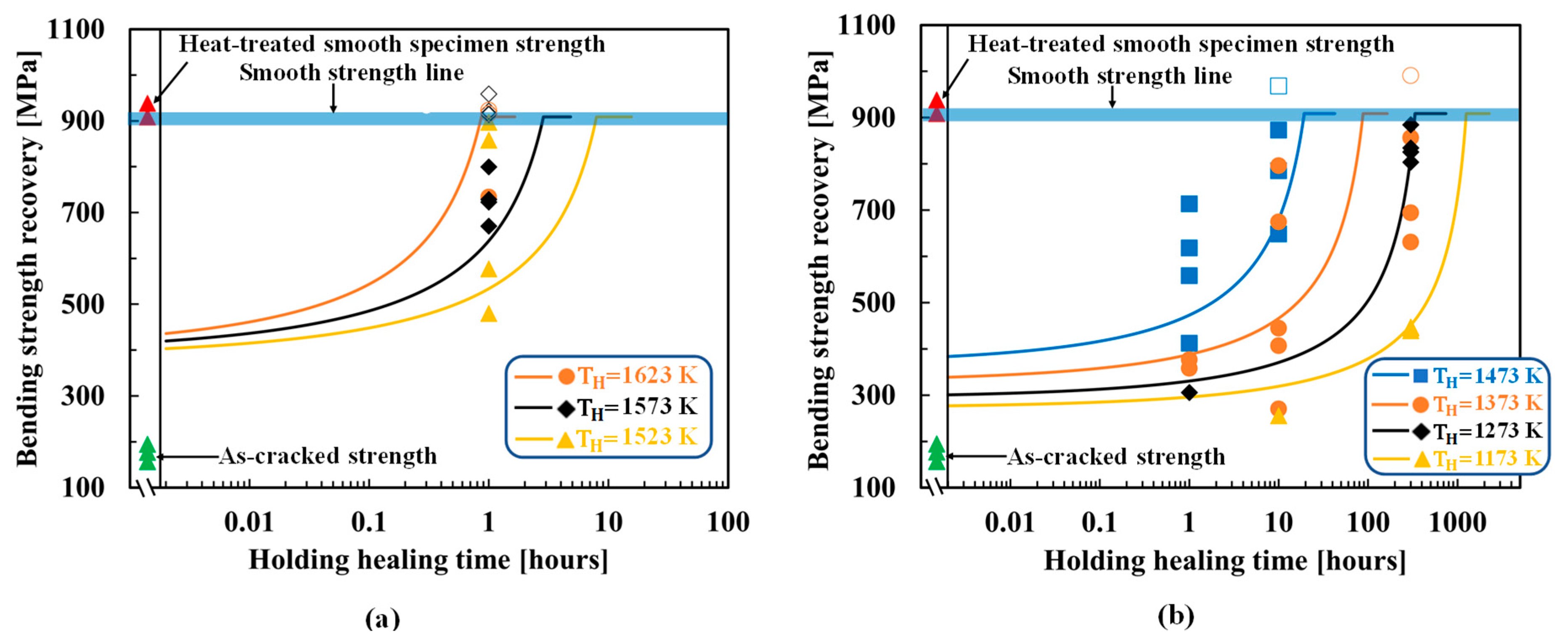
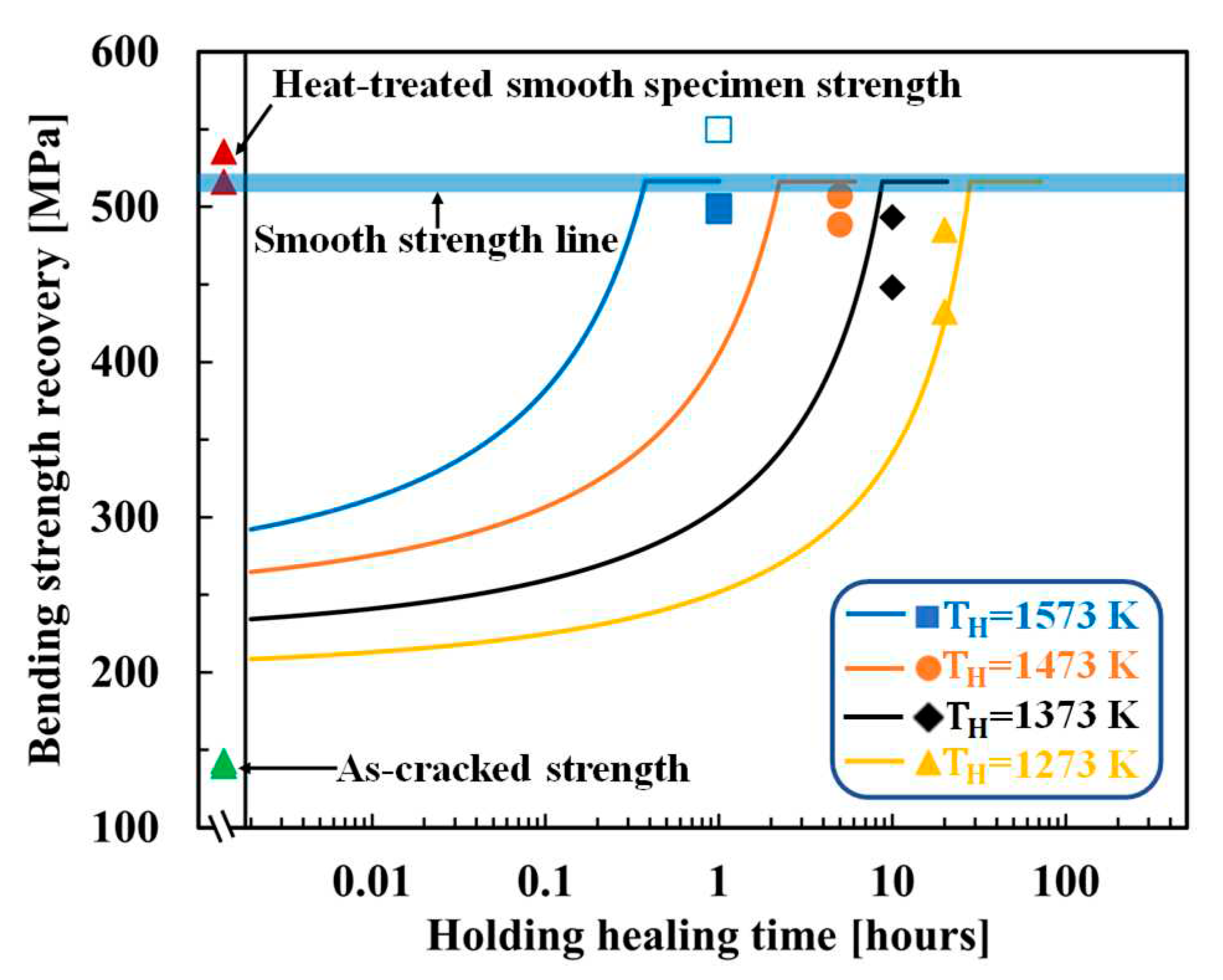
Figure 4 shows the optimized results for AS15P. Here, the healing temperatures of AS15P ranging from 1173 K to 1623 K are separated into two groups, high-temperature (1523–1623 K) and low-temperature (1173–1473 K) groups, to clearly compare the experimental and theoretical strength recovery behaviors. AS15P outputs an AE of 138 kJ/mol and an FF of 9.50 × 10 6 k g 2 m 4 s , which exhibits a reasonable agreement between the experimental and theoretical strength recovery behaviors. The optimized results for MS20P are shown in Figure 5. MS20P outputs an AE of 113 kJ/mol and an FF of 6.0 × 10 6 k g 2 m 4 s , which also shows an agreement between the experimental and theoretical strength recovery behaviors.

4.2. TiC–HA-based alumina composite

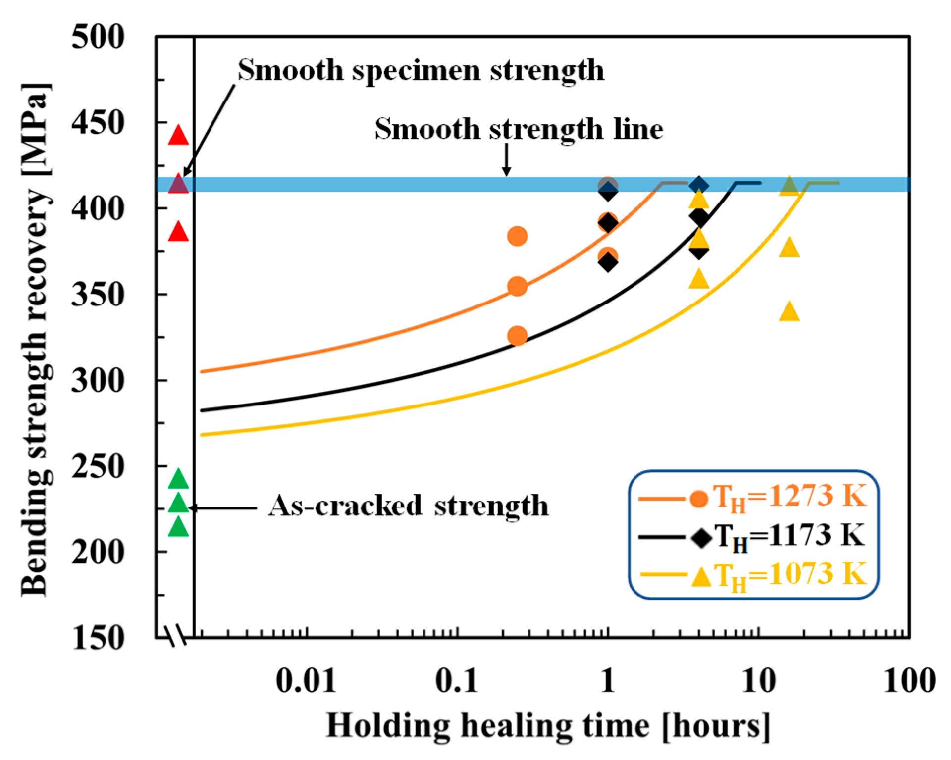
Yoshioka et al. [42] showed that complete strength recovery in TiC-HA-based alumina composites and even more than smooth specimen strength can be achieved at 1073 K/1 hr./air, which signifies that TiC oxidizes at a low AE and high FF compared with SiC. Figure 6 shows the optimized results for AT30P and AT15P. The figure also shows the experimental as-cracked strength and heat-treated smooth specimen strength. Because this composite exhibits a large scatter of strength, the strength of smooth specimen represented by blue bold lines is adopted for σ 0 . TiC exhibits a higher oxidation capability as AT30P and AT15P recover the as-cracked strength to a smooth strength under a lower healing temperature and time, as shown in Figure 6. Here, crack propagation along the matrix–HA interface is considered owing to the confusion regarding the crack propagation direction from the SEM images reported in [42].
Interestingly, AT30P and AT15P output the same AE of 101 kJ/mol and almost the same FF of 5.20 × 10 3 k g 2 m 4 s and 9.0 × 10 3 k g 2 m 4 s , respectively, if cracks propagate along the matrix–HA interface. The optimized parameters exhibited suitable agreement between the experimental and theoretical strength recovery behaviors, as shown in Figure 6.

4.3. MAX-phase HA-based alumina composite

Boatemaa et al. [41] analyzed the autonomous surface crack healing of alumina reinforced with 20 vol.% T i 2 AlC and found the strength to be completely recovered at healing temperatures ranging from 1073 K to 1273 K for time 0.2–16 hr. Figure 7 shows the optimized results for AMAX20P; the figure also shows the experimental as-cracked strength and heat-treated smooth specimen strength. Because this composite also exhibits a large scatter of strength, the strength of smooth specimen represented by blue bold lines is adopted for σ 0 . In this composite, crack propagation through HA was considered for T i 2 AlC oxidation, and reasonable agreement was observed between the experimental and theoretical strength recovery behaviors. AMAX20P outputs an AE of 101 kJ/mol and FF of 1.80 × 10 7 k g 2 m 4 s , if cracks propagate through HA.

5. Discussion

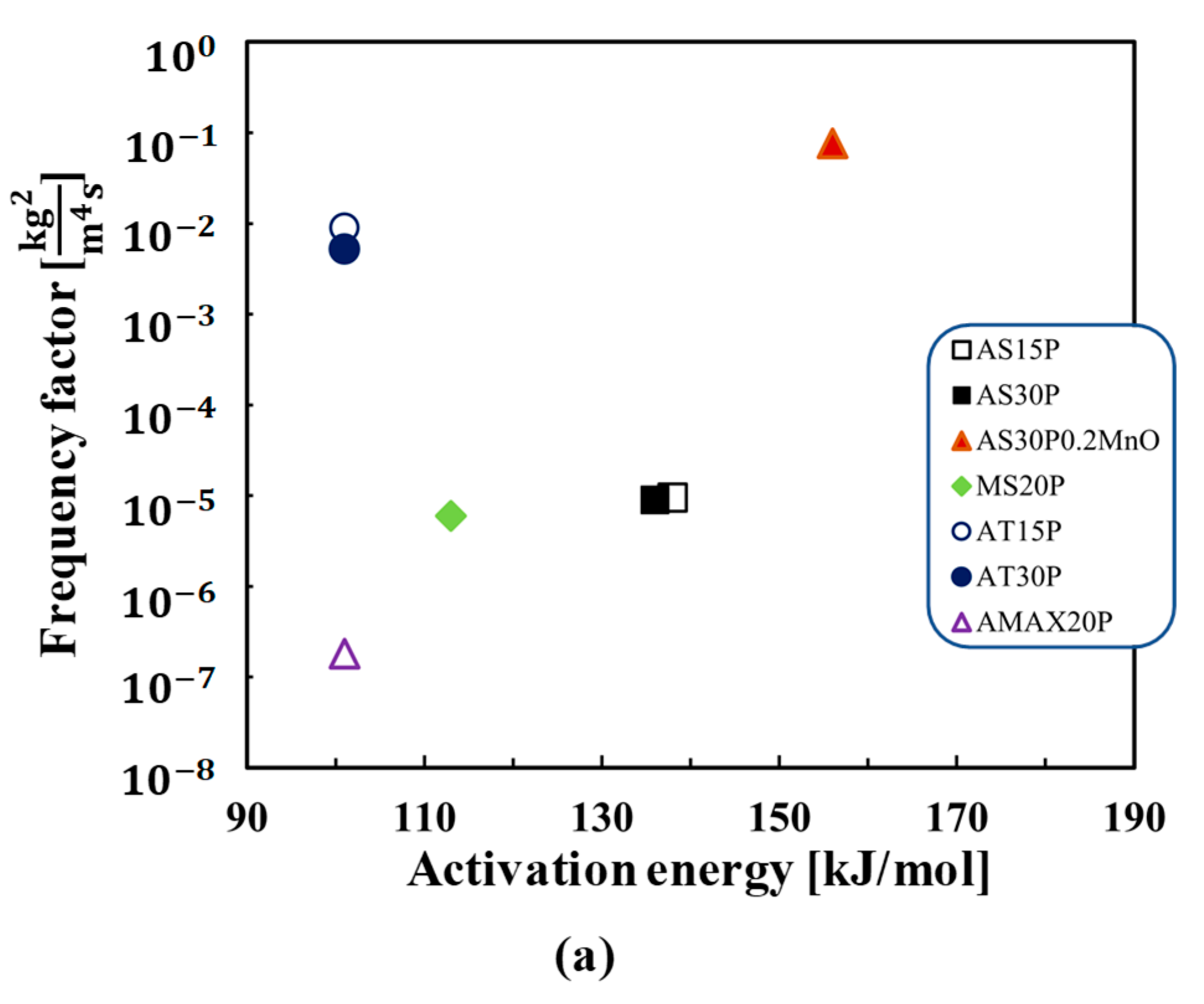
Figure 8a–c summarize the determined AE and FF of HA-oxidation, Arrhenius plot of determined HAs-oxidation rate for the self-healing ceramic composites, and Arrhenius plot of average strength recovery rate, respectively. As shown in Figure 8a, the AE and FF for HA-oxidation determined from AS15P is similar values to those of AS30P, despite different f v of HAs. Further, AE and FF for AT15P also show almost similar values to AT30P. This implies the kinetics model mentioned in Section 2 can accurately describe the effect of f v of HAs on the strength recovery by self-healing. In SiC–HA-based alumina and mullite composites, the AE of SiC oxidation is different in the case of alumina and mullite matrices, despite of the same SiC type-HA. Further, the AS30P0.2MnO show the quite larger values of FF than SiC–HA-based alumina and mullite composites. The TiC–HA-based alumina composite exhibited a lower AE and higher FF than the other composites. Meanwhile, FF of the   T i 2 AlC–HA-based alumina composite is lower than those of the SiC–HA-based alumina, mullite, and TiC–HA-based alumina composites, whereas AE is lower than that of the SiC–HA-based composites.
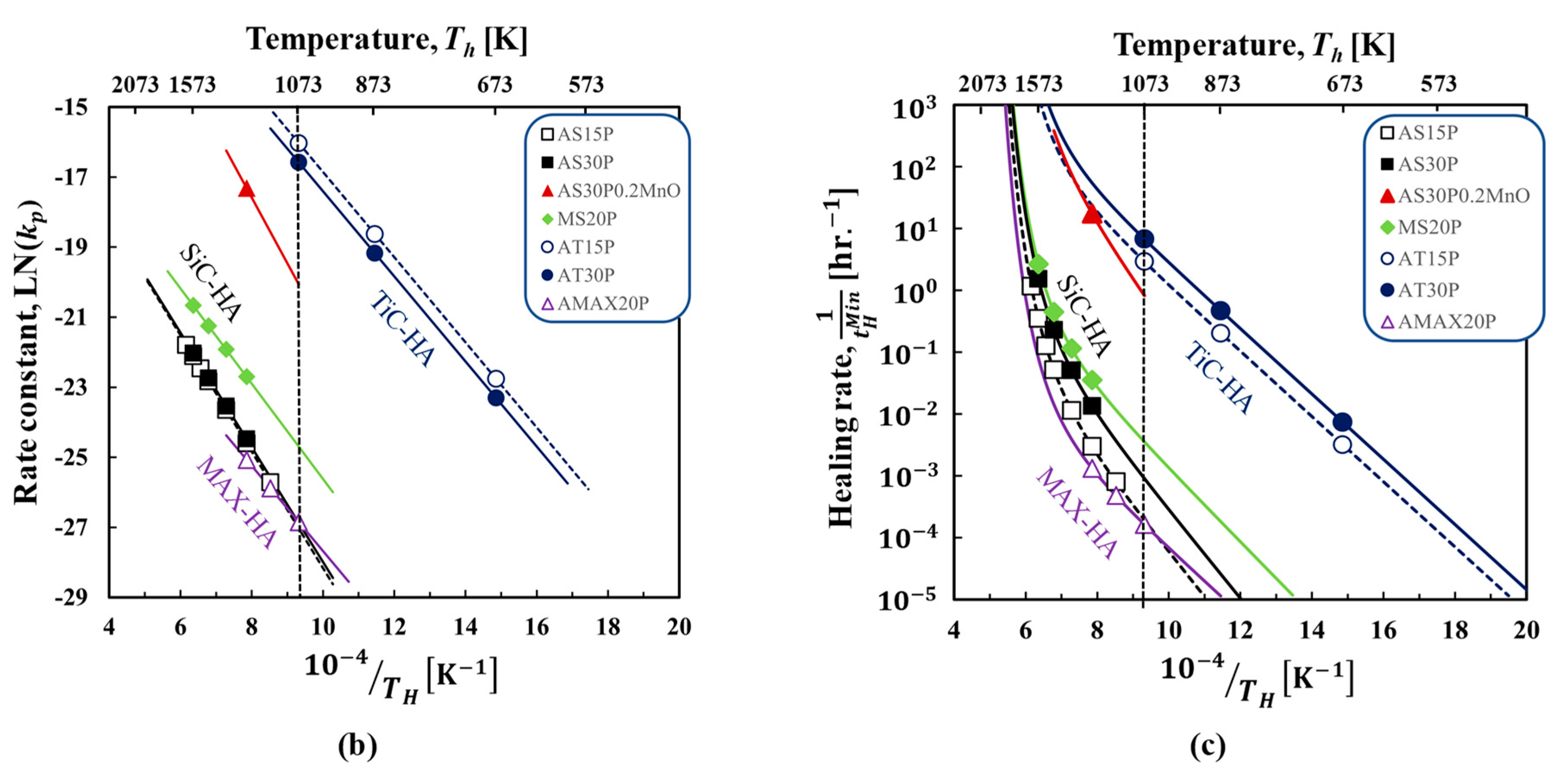
Further, Arrhenius plot of the rate constant kp of HA-oxidation calculated by Equation (2) imputing the determined AE and FF in Figure 8a also shown in Figure 8b. For TiC-, SiC- and MAX-HAs, the linear line can be calculated for k p of HAs-oxidation. The figure clearly shows that the values of k p are in the order of TiC-HA > SiC-HA(MnO) >>SiC-HA(Mullite)> SiC-HA (alumina)~MAX-HA. Further it is worthy to mention that the k p of SiC oxidation is different in the case of alumina and mullite matrices, despite of the same SiC type-HA. Further large values for k p of HA-oxidation can be realized by the MnO healing activator addition. This can be explained by dissolution of matrix or healing activator into SiO2 formed by SiC-HA-oxidation during ‘repair stage’ as reported in [46]. This dissolution during repair stage can decrease the glass transition temperature and viscosity of healing product resulting in rapid diffusion of O2 and volume gain V h   in Equation (4).
As shown in Figure 8c, average strength recovery rate R s ¯ calculated by the Equation (20) [39] using the determined AE and FF in Figure 8a allows to comparison of self-healing ability for all composites under the same damage size (crack size, 2c is 100 μm in Figure 2). This is helpful for self-healing ceramics composites design. Here, average strength recovery rate can be calculated from the minimum time required for complete strength recovery in the case of isothermal oxidation [15] [39] as follows:
R s ¯ = 1 / t H M i n = 2 A f v f e ρ V g 2 k p 0 e x p Q o x R T H P O 2 P O 2 0 m .
As shown in Figure 8c, AT30P and AT15P exhibited higher strength recovery rates than the other composites, resulting in TiC oxidation at low temperatures and less time for complete crack healing and strength recovery (Figure 6). Further it is worthy to mention that that R s ¯ of AS30P0.2MnO is at 1273K is the almost same as that of AT15P, although the values of k p of SiC-HA(MnO) is lower than that of TiC-HA. This is due to the fact that the values of ρ for SiC-HA is smaller than that of TiC-HA, suggesting that the importance of selection of healing products for self-healing ceramics design. Further the data plot shows linear line approximately below 1073 K. Meanwhile, for the SiC type-HA including AS15P, AS30P, MS20P and AS30P0.2MnO, data plots show the nonlinear lines, since the crack closure by residual stress release approximately above 1073 K as described by Equation (11). Further the R s ¯   by SiC types-HA oxidation is in the order of AS30P0.2MnO >> MS20P > AS30P > AS15P, suggesting that the selection of healing activator and matrix together with HA is also important in designing ceramics realizing rapid self-healing of surface crack.
In this way, we demonstrated that the proposed framework allows to discuss the self-healing ability for all composites by using only the limited data set of strength recovery. Notably, the effect of both AE and FF on oxidation rate, volume-gain rate, crack-gap filling, and healing rate corresponding to temperature and time can be reasonably described by the universal kinetics model of strength recovery. Furthermore, the kinetic parameters AE and FF of self-healing ceramic composites, which are necessary for the examination of practical applications, can be determined using the proposed framework.

6. Conclusions

This study proposed a novel framework for determining the kinetics parameters of self-healing ceramic composites using experimental strength recovery data, micro-structural features, and exact experimental conditions by adopting a universal kinetics model of strength recovery [39]. The proposed method can reasonably explore kinetic parameters, and its effectiveness is demonstrated by comparing the experimental and theoretical strength recovery behaviors under several healing conditions. TiC and MAX-phase HAs having higher oxidation capabilities than SiC-HA, even at low temperatures, can be confirmed in terms of AE and FF; both these parameters play significant roles in rapid strength recovery, depending on the temperature conditions and time during service.
Note that the proposed framework based on the universal kinetics model can be applied to estimate the kinetic parameters for not only commonly used HAs, such as SiC, TiC, and Ti2AlC, but also other HAs. Moreover, the obtained parameters can be used for finite element analysis of self-healing under arbitrary environmental conditions [38]. Collectively, the proposed method will be helpful in selecting HA and matrices for the design of next-generation self-healing ceramic composites used in high-temperature applications. To further refine the parameter determination method, the super healing phenomenon and recovery of the fracture toughness of self-healing ceramics owing to healing should be examined in the future.
Author contribution: Mostafizur Rahman proposed the parameter determination method, analyzed the data, and wrote the paper. Maeda Taiyo modified the program. Toshio Osada and Shingo Ozaki conceptualized and designed the study.

Funding

This study was supported by a Grant-in-Aid for Scientific Research [Grant No. (B) 22H01357], the Japan Society for the Promotion of Science (JSPS), Japan.

Institutional Review Board Statement

Not applicable

Informed Consent Statement

Not applicable

Data Availability Statement

Not applicable

Acknowledgments

We would like to thank Editage (www.editage.com) for English language editing.

Conflicts of Interest

The authors declare that they have no known conflicts of interest.

References

  1. Greil, P. Self-Healing Engineering Ceramics with Oxidation-Induced Crack Repair. Adv. Eng. Mater. 2020, 22, 1–8. [Google Scholar] [CrossRef]
  2. Levine, S.R.; Opila, E.J.; Halbig, M.C.; Kiser, J.D.; Singh, M.; Salem, J.A. Evaluation of Ultra-High Temperature Ceramics for Aeropropulsion Use. J. Eur. Ceram. Soc. 2002, 22, 2757–2767. [Google Scholar] [CrossRef]
  3. Padture, N.P. Advanced Structural Ceramics in Aerospace Propulsion. Nat. Mater. 2016, 15, 804–809. [Google Scholar] [CrossRef]
  4. Quinn, G.D.; Morrell, R. Design Data for Engineering Ceramics: A Review of the Flexure Test. J. Am. Ceram. Soc. 1991, 74, 2037–2066. [Google Scholar] [CrossRef]
  5. Purohit, R.; Gupta, N.K.; Purohit, M.R.; Patil, A.; Bharilya, R.K.; Singh, S.K. An Investigation on Manufacturing of Self-Healing Materials. Mater. Today Proc. 2015, 2, 3371–3377. [Google Scholar] [CrossRef]
  6. van der Zwaag, S. An Introduction to Material Design Principles: Damage Prevention versus Damage Management. Springer Ser. Mater. Sci. 2007, 100, 1–18. [Google Scholar]
  7. Huet, R.; Sakona, A.; Kurtz, S.M. Strength and Reliability of Alumina Ceramic Femoral Heads: Review of Design, Testing, and Retrieval Analysis. J. Mech. Behav. Biomed. Mater. 2011, 4, 476–483. [Google Scholar] [CrossRef]
  8. Sitnikov, N.N.; Khabibullina, I.A.; Mashchenko, V.I.; Rizakhanov, R.N. Prospects of Application of Self-Healing Materials and Technologies Based on Them. Inorg. Mater. Appl. Res. 2018, 9, 785–793. [Google Scholar] [CrossRef]
  9. H. Heuer and J. P. Roberts. The Influence of Annealing on the Strength of Corundum Crystals. Proc. Br. Ceram. Soc. 1966, 6, 17–27.
  10. LANGE, F.F.; GUPTA, T.K. Crack Healing by Heat Treatment. J. Am. Ceram. Soc. 1970, 53, 54–55. [Google Scholar] [CrossRef]
  11. Chu, M.C.; Sato, S.; Kobayashi, Y.; Ando, K. DAMAGE HEALING AND STRENGTHENING BEHAVIOUR IN INTELLIGENT MULLITE/SiC CERAMICS. Fatigue Fract. Eng. Mater. Struct. 1995, 18, 1019–1029. [Google Scholar] [CrossRef]
  12. Ando, K.; Ikeda, T.; Sato, S.; Yao, F.; Kobayasi, Y. A Preliminary Study on Crack Healing Behaviour of Si3N4/SiC Composite Ceramics. Fatigue Fract. Eng. Mater. Struct. 1998, 21, 119–122. [Google Scholar] [CrossRef]
  13. K. ANDO, M.C. CHU, F.Y. and S. S. Fatigue Strength of Crack-Healed Si3N4/SiC Composite Ceramics. Fatigue Fract. Eng. Mater. Struct. 1999, 22, 897–903.
  14. Osada, T.; Nakao, W.; Takahashi, K.; Ando, K.; Saito, S. Strength Recovery Behavior of Machined Al2O3/SiC Nano-Composite Ceramics by Crack-Healing. J. Eur. Ceram. Soc. 2007, 27, 3261–3267. [Google Scholar] [CrossRef]
  15. Osada, T.; Nakao, W.; Takahashi, K.; Ando, K. Kinetics of Self-Crack-Healing of Alumina/Silicon Carbide Composite Including Oxygen Partial Pressure Effect. J. Am. Ceram. Soc. 2009, 92, 864–869. [Google Scholar] [CrossRef]
  16. Chlup, Z.; Flasar, P.; Kotoji, A.; Dlouhy, I. Fracture Behaviour of Al2O3/SiC Nanocomposite Ceramics after Crack Healing Treatment. J. Eur. Ceram. Soc. 2008, 28, 1073–1077. [Google Scholar] [CrossRef]
  17. Liu, S.P.; Ando, K. Fatigue Strength Characteristics of Crack-Healing Materials - Al2O3/SiC Composite Ceramics and Monolithic Al2O3. J. Chinese Inst. Eng. Trans. Chinese Inst. Eng. A/Chung-kuo K. Ch’eng Hsuch K’an 2004, 27, 395–404. [Google Scholar] [CrossRef]
  18. Boatemaa, L.; Brouwer, J.C.; van der Zwaag, S.; Sloof, W.G. The Effect of the TiC Particle Size on the Preferred Oxidation Temperature for Self-Healing of Oxide Ceramic Matrix Materials. J. Mater. Sci. 2018, 53, 5973–5986. [Google Scholar] [CrossRef]
  19. Chen, Z.; Ji, L.; Guo, N.; Xu, C.; Zhang, S. Crack Healing and Strength Recovery of Al2O3/TiC/TiB2 Ceramic Tool Materials. Int. J. Refract. Met. Hard Mater. 2020, 87, 105167. [Google Scholar] [CrossRef]
  20. Maruoka, D.; Nanko, M. Recovery of Mechanical Strength by Surface Crack Disappearance via Thermal Oxidation for Nano-Ni/Al2O3 Hybrid Materials. Ceram. Int. 2013, 39, 3221–3229. [Google Scholar] [CrossRef]
  21. Maruoka, D.; Sato, Y.; Nanko, M. Crack-Healing Effectiveness of Nano Ni + SiC Co-Dispersed Alumina Hybrid Materials. Adv. Mater. Res. 2010, 89–91, 365–370. [Google Scholar] [CrossRef]
  22. Salas-Villaseñor, A.L.; Lemus-Ruiz, J.; Nanko, M.; Maruoka, D. Crack Disappearance by High-Temperature Oxidation of Alumina Toughened by Ni Nano-Particles. Adv. Mater. Res. 2009, 68, 34–43. [Google Scholar] [CrossRef]
  23. Nakao, W.; Ono, M.; Lee, S.K.; Takahashi, K.; Ando, K. Critical Crack-Healing Condition for SiC Whisker Reinforced Alumina under Stress. J. Eur. Ceram. Soc. 2005, 25, 3649–3655. [Google Scholar] [CrossRef]
  24. Takahashi, K.; Jung, Y.S.; Nagoshi, Y.; Ando, K. Crack-Healing Behavior of Si3N4/SiC Composite under Stress and Low Oxygen Pressure. Mater. Sci. Eng. A 2010, 527, 3343–3348. [Google Scholar] [CrossRef]
  25. Hu, J.F.; Deng, X.; Xu, T.Z.; Chen, Z. Experimental and Theoretical Investigation on the Effect of Crack Dimension on the Crack-Healing Performance of Si3N4/SiCw Composite Ceramic. Results Phys. 2019, 14, 102411. [Google Scholar] [CrossRef]
  26. Saucedo-Mora, L.; Mostafavi, M.; Khoshkhou, D.; Reinhard, C.; Atwood, R.; Zhao, S.; Connolly, B.; Marrow, T.J. Observation and Simulation of Indentation Damage in a SiC-SiCfibre Ceramic Matrix Composite. Finite Elem. Anal. Des. 2016, 110, 11–19. [Google Scholar] [CrossRef]
  27. Nakatani, M.; Nishimura, J.; Hanaki, S.; Uchida, H. Crack-Healing Behavior Induced by Oxidation in SiN/SiC Nanolaminated Films. Thin Solid Films 2014, 556, 68–73. [Google Scholar] [CrossRef]
  28. Ando, K.; Furusawa, K.; Chu, M.C.; Hanagata, T.; Tuji, K.; Sato, S. Crack-Healing Behavior under Stress of Mullite/Silicon Carbide Ceramics and the Resultant Fatigue Strength. J. Am. Ceram. Soc. 2001, 84, 2073–2078. [Google Scholar] [CrossRef]
  29. Lee, S.K.; Ono, M.; Nakao, W.; Takahashi, K.; Ando, K. Crack-Healing Behaviour of Mullite/SiC/Y2O3 Composites and Its Application to the Structural Integrity of Machined Components. J. Eur. Ceram. Soc. 2005, 25, 3495–3502. [Google Scholar] [CrossRef]
  30. Nam, K.W.; Hwang, J.R. The Crack Healing Behavior of ZrO 2/SiC Composite Ceramics with TiO 2 Additive. J. Mech. Sci. Technol. 2012, 26, 2093–2096. [Google Scholar] [CrossRef]
  31. Song, G.M.; Pei, Y.T.; Sloof, W.G.; Li, S.B.; De Hosson, J.T.M.; van der Zwaag, S. Oxidation-Induced Crack Healing in Ti3AlC2 Ceramics. Scr. Mater. 2008, 58, 13–16. [Google Scholar] [CrossRef]
  32. Sloof, W.G.; Pei, R.; McDonald, S.A.; Fife, J.L.; Shen, L.; Boatemaa, L.; Farle, A.S.; Yan, K.; Zhang, X.; Van Der Zwaag, S.; Lee, P.D.; Withers, P.J. Repeated Crack Healing in MAX-Phase Ceramics Revealed by 4D in Situ Synchrotron X-Ray Tomographic Microscopy. Sci. Rep. 2016, 6, 1–9. [Google Scholar] [CrossRef] [PubMed]
  33. Yang, H.J.; Pei, Y.T.; Rao, J.C.; De Hosson, J.T.M. Self-Healing Performance of Ti 2AlC Ceramic. J. Mater. Chem. 2012, 22, 8304–8313. [Google Scholar] [CrossRef]
  34. Li, S.; Song, G.; Kwakernaak, K.; van der Zwaag, S.; Sloof, W.G. Multiple Crack Healing of a Ti 2AlC Ceramic. J. Eur. Ceram. Soc. 2012, 32, 1813–1820. [Google Scholar] [CrossRef]
  35. Song, G.M.; Schnabel, V.; Kwakernaak, C.; Van Der Zwaag, S.; Schneider, J.M.; Sloof, W.G. High Temperature Oxidation Behaviour of Ti2AlC Ceramic at 1200°C. Mater. High Temp. 2012, 29, 205–209. [Google Scholar] [CrossRef]
  36. Ozaki, S.; Osada, T.; Nakao, W. Finite Element Analysis of the Damage and Healing Behavior of Self-Healing Ceramic Materials. Int. J. Solids Struct. 2016, 100–101, 307–318. [Google Scholar] [CrossRef]
  37. Kurumatani, M.; Terada, K.; Kato, J.; Kyoya, T.; Kashiyama, K. An Isotropic Damage Model Based on Fracture Mechanics for Concrete. Eng. Fract. Mech. 2016, 155, 49–66. [Google Scholar] [CrossRef]
  38. Ozaki, S.; Yamamoto, J.; Kanda, N.; Osada, T. Kinetics-Based Constitutive Model for Self-Healing Ceramics and Its Application to Finite Element Analysis of Alumina/SiC Composites. Open Ceram. 2021, 6, 100135. [Google Scholar] [CrossRef]
  39. Osada, T.; Hara, T.; Mitome, M.; Ozaki, S.; Abe, T.; Kamoda, K.; Ohmura, T. Self-Healing by Design: Universal Kinetic Model of Strength Recovery in Self-Healing Ceramics. Sci. Technol. Adv. Mater. 2020, 21, 593–608. [Google Scholar] [CrossRef]
  40. Nakao, W.; Abe, S. Enhancement of the Self-Healing Ability in Oxidation Induced Self-Healing Ceramic by Modifying the Healing Agent. Smart Mater. Struct. 2012, 21. [Google Scholar] [CrossRef]
  41. Boatemaa, L.; Bosch, M.; Farle, A.S.; Bei, G.P.; van der Zwaag, S.; Sloof, W.G. Autonomous High-Temperature Healing of Surface Cracks in Al2O3 Containing Ti2AlC Particles. J. Am. Ceram. Soc. 2018, 101, 5684–5693. [Google Scholar] [CrossRef]
  42. Yoshioka, S.; Boatemaa, L.; Zwaag, S. van der; Nakao, W.; Sloof, W.G. On the Use of TiC as High-Temperature Healing Particles in Alumina Based Composites. J. Eur. Ceram. Soc. 2016, 36, 4155–4162. [Google Scholar] [CrossRef]
  43. Ando, K.; Shirai, Y.; Nakatani, M.; Kobayashi, Y.; Sato, S. (Crack-Healing + Proof Test): A New Methodology to Guarantee the Structural Integrity of a Ceramics Component. J. Eur. Ceram. Soc. 2002, 22, 121–128. [Google Scholar] [CrossRef]
  44. Ando, K.; Furusawa, K.; Takahashi, K.; Sato, S. Crack-Healing Ability of Structural Ceramics and a New Methodology to Guarantee the Structural Integrity Using the Ability and Proof-Test. J. Eur. Ceram. Soc. 2005, 25, 549–558. [Google Scholar] [CrossRef]
  45. Newman, J.C.; Raju, I.S. An Empirical Stress-Intensity Factor Equation for the Surface Crack. Eng. Fract. Mech. 1981, 15, 185–192. [Google Scholar] [CrossRef]
  46. Osada, T.; Kamoda, K.; Mitome, M.; Hara, T.; Abe, T.; Tamagawa, Y.; Nakao, W.; Ohmura, T. A Novel Design Approach for Self-Crack-Healing Structural Ceramics with 3D Networks of Healing Activator. Sci. Rep. 2017, 7, 1–2. [Google Scholar] [CrossRef]
  47. COSTELLO, J.A.; TRESSLER, R.E. Oxidation Kinetics of Hot-Pressed and Sintered A-SiC. J. Am. Ceram. Soc. 1981, 64, 327–331. [Google Scholar] [CrossRef]
  48. Ando, K.; Kim, B.S.; Chu, M.C.; Saito, S.; Takahashi, K. Crack-Healing and Mechanical Behaviour of Al2O3/SiC Composites at Elevated Temperature. Fatigue Fract. Eng. Mater. Struct. 2004, 27, 533–541. [Google Scholar] [CrossRef]
  49. Ando, K. ;, Min-Cheol Chu, Kiichi Tsuji, T. H.; Yasuyoshi Kobayashi, S.S. Crack Healing Behaviour and High-Temperature Strength of Mullite/SiC Composite Ceramics. J. Eur. Ceram. Soc. 2002, 22, 1313–1319. [Google Scholar]
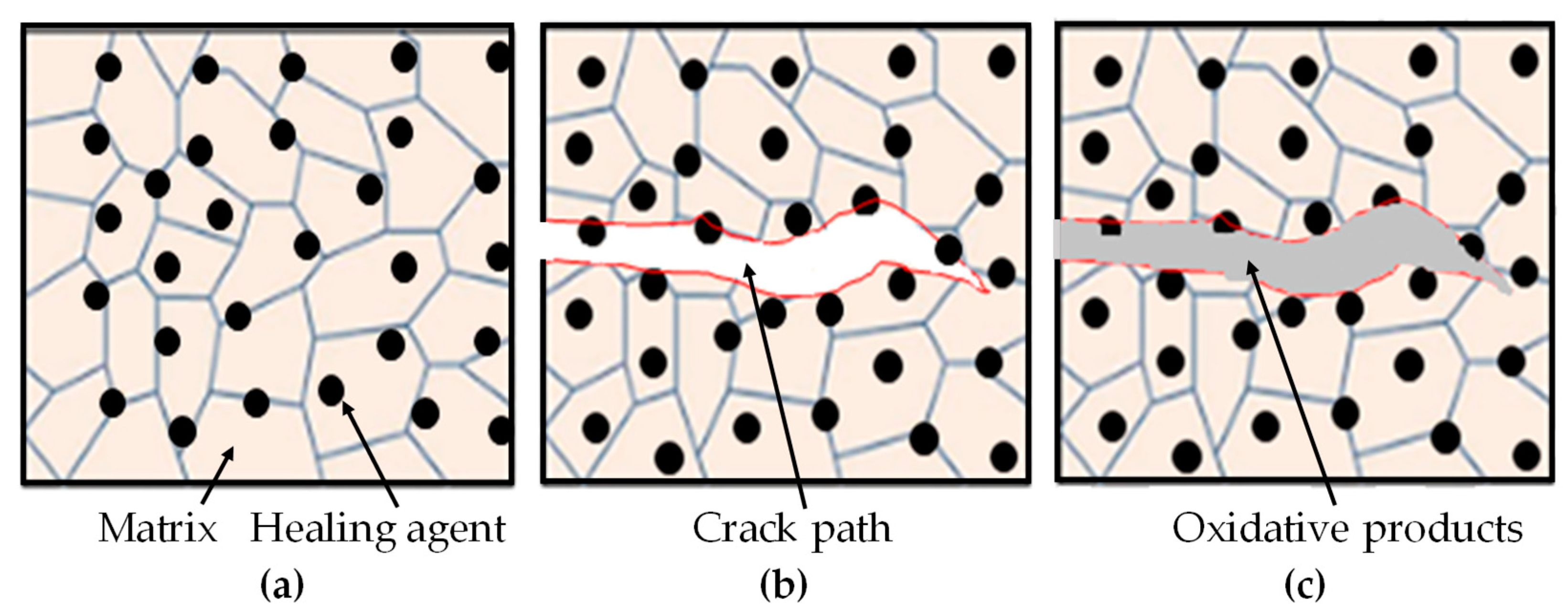
Figure 1. Schematic illustration of crack-gap filling by oxidative products produced from oxidation reaction of HAs incorporated within matrix: (a) HAs are located within the matrix such that micro-size HAs locate on the grain boundary and nano-size HAs on the grain structure; (b) crack initiation, propagation direction both along interface of matrix-HAs and through HAs, this propagation direction depends on mechanical properties between matrix and HAs; (c) crack-gap filling by oxidative products, this filling could be complete or partial depending on healing conditions.
Preprints 71704 g001
Figure 2. Schematic illustration of tip-to-mouth crack-gap filling by oxidation products produced from HAs. SiO2, TiO2, and Al2O3 fill the crack-gap and make a strong bonding with matrix using the heat produced from this exothermic healing reactions. Remaining crack size c R   a s calculated from Equation (14) measures the level of the cracked strength recovery.
Preprints 71704 g002
Figure 3. Comparison of strength recovery behavior between experimental and theoretical results: (a) AS30P [39]; (b) AS30P0.2MnO [46]. Colored smooth lines correspond to theoretical strength recovery using determined AE and FF. Different shaped plots correspond to experimental strength recovery with different holding healing temperature and time. Open plots represent the super healing conditions, are not used to determine AE and FF.
Preprints 71704 g003
Figure 4. Comparison of strength recovery behavior of AS15P [48] between experimental and theoretical results: (a) temperature from 1523 K to 1623 K; (b) temperature from 1173 K to 1473 K. Colored smooth lines correspond to theoretical strength recovery using determined AE and FF. Different shaped plots correspond to experimental strength recovery with different holding healing temperature and time. Open plots represent the super healing conditions, are not used to determine AE and FF.
Preprints 71704 g004
Figure 5. Comparison of strength recovery behavior of MS20P [49] between experimental and theoretical results. Colored smooth lines correspond to theoretical strength recovery using determined AE and FF. Different shaped plots correspond to experimental strength recovery with different holding healing temperature and time. Open plots represent the super healing conditions, are not used to determine AE and FF.
Preprints 71704 g005
Figure 6. Comparison of strength recovery behavior of TiC-HA based alumina composite [42]: (a) AT30P; (b) AT15P. Colored smooth lines correspond to theoretical strength recovery using determined AE and FF from tip-to-mouth filling model. Different shaped plots correspond to experimental strength recovery with different holding healing temperature and rtime. Open plots represent the super healing conditions, are not used to determine AE and FF. Here, middle data is used as strength of smooth specimen, σ 0 . This method can also confirm almost same AE & FF if most upper point is used as smooth specimen strength,   σ 0 .
Preprints 71704 g006
Figure 7. Comparison of strength recovery behavior of AMAX20P [41] between experimental and theoretical results. Colored smooth and dashed lines correspond to theoretical strength recovery using determined AE and FF from tip-to-mouth filling model. Different shaped plots correspond to experimental strength recovery with different holding healing temperature and time. Here, middle data is used as strength of smooth specimen, σ 0 .
Preprints 71704 g007
Figure 8. Summary of determined kinetic parameters of self-healing ceramics composite: (a) determined AE and FF for HA-oxidation (b) Arrhenius plot of oxidation rate; (c) Arrhenius plot of average strength recovery rate. Here, oxidation and healing rate are calculated using determined AE and FF considering the same damage size (2c =100 μm), TH is the holding healing temperature of the composites in details, AS15P 1173 K ~ 1623 K , AS30P 1273 K ~ 1573 K ,   A S 30 P 0.2 M n O ( 1273 K ) MS20P 1273 K ~ 1573 K , AT30P & AT15P 673 K ~ 1073 K , AMAX20P 1073 K ~ 1273 K . The lines are calculated values and plots are the optimization points corresponding to experimental values.
Preprints 71704 g008aPreprints 71704 g008b
Table 1. Different self-healing ceramic composites along with damage formation method, healing conditions, and bending strength test method. Al2O3, Mullite, Si3N4, ZrO2, and Ti2AlC are the matrix of material composition. (p) and (w) represent healing agent’s particle and whisker. Experimental strength recovery behaviors, healing conditions, and micro-structural features on fractured surfaces of AS15P [48], AS30P [39], AS30P0.2MnO [46], MS20P [49], AT15P [42], AT30P [42], AMAX20P [41], and composites are considered for this study.
Preprints 71704 i001
Disclaimer/Publisher’s Note: The statements, opinions and data contained in all publications are solely those of the individual author(s) and contributor(s) and not of MDPI and/or the editor(s). MDPI and/or the editor(s) disclaim responsibility for any injury to people or property resulting from any ideas, methods, instructions or products referred to in the content.
Copyright: This open access article is published under a Creative Commons CC BY 4.0 license, which permit the free download, distribution, and reuse, provided that the author and preprint are cited in any reuse.
Prerpints.org logo

Preprints.org is a free preprint server supported by MDPI in Basel, Switzerland.

Subscribe

© 2024 MDPI (Basel, Switzerland) unless otherwise stated