1. Introduction
Valves and pipes used in offshore plants require high strength and corrosion resistance because they are used in seawater [
1,
2,
3]. Among various materials, super duplex stainless steel (SDSS) is suitable for application in offshore plants [
4,
5,
6]. However, the manufacturing of SDSS is difficult. SDSS is a dual phase stainless steel composed of austenite and ferrite, which causes various issues, such as high temperature cracking due to phase transformation during high temperature forging [
7,
8,
9]. From the high temperature crack analysis, the secondary phase is confirmed to develop within 20 mm of the interior. And the material has broken by the crack.
The large casting of SDSS results in a difference in the volume fraction of austenite, ferrite, and secondary phase (Sigma, Chi, CrN, and Cr
23C
6) owing to the difference in the cooling rate between the inside and outside, causing various issues [
4,
5]. When the secondary phase is precipitated inside, hot temperature cracking occurs, decreasing the corrosion resistance. Although significant research efforts have been devoted to suppress the precipitation of secondary phases, no studies have been conducted on the effects of the secondary phase on solution annealing [
10,
11,
12].
Extensive research on the manufacturing of SDSS for welding and heat treatment has also been conducted. Nilson and Shin studied is the heat treatment effect on the volume fraction of phased and electrochemical properties [
4,
5,
13,
14]. The studies investigated the effect of the equilibrium volume fraction on the electrochemical properties but did not examine the effect of the secondary phase on the solution annealing process. Kose conducted a study on the microstructure and strength of steel after laser welding for advanced pipe manufacture [
6]. Although many studies on SDSS have been conducted, studies on the effect of secondary phase precipitation on solution annealing have not been conducted.
In this study, the change in the solution annealing characteristics with the volume fraction of the secondary phase was electrochemically measured. After heat treatment at 900-1050℃ to precipitate the secondary phase, solution annealing was performed at 1100℃. The microstructure under the heat treatment conditions was analyzed using field emission scanning microscopy (FE-SEM), and the volume fraction of each phase was measured at a magnification of x200. Electron probe micro analysis (EPMA) and X-ray diffraction (XRD) were used to confirm the precipitation of the secondary phase. The electrochemical properties were measured using potentiodynamic polarization and critical pitting temperature (CPT) tests.
2. Experimental
2.1. Materials and heat treatmetn
The SDSS used was SDSS2507, which is commonly used for manufacturing valves and pipes in offshore plants. Its components are listed in
Table 1. After casting, and cooling, the microstructure and composition after heat treatment were examined at four temperature 900-1050℃ (tests were conducted for four temperature; 50℃ increments) in increments of 50℃ to confirm the effect of the secondary phase on the high termperature cracking and corrosion resistance of SDSS2507 [
4,
5]. Cooling method is water quenching, and the cooling rate is 50℃/s.
2.2. Microstructure and volume fraction
For the experiment, the microstructure was polished with diamond paste. After etching for 1min in 5 wt.%KOH electrolyte, it was confirmed using FE-SEM (Hitachi) [
13]. The secondary phase was confirmed using X-ray diffraction (XRD), and the chemical composition was determined via EPMA and EDS after polishing. The chemical composition of nitrogen was calculated according to the maximum solution of ferrite it is impossible to analyze the concentration of quantitatively using EDS [
4,
5,
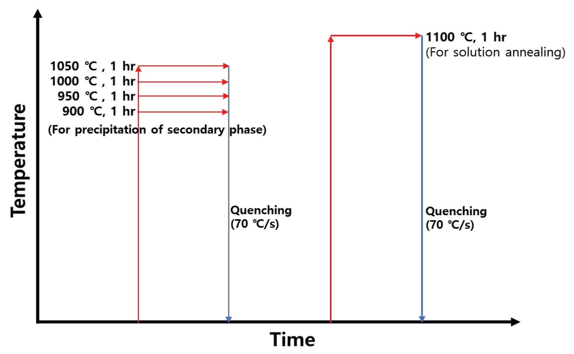
6]. After the secondary phase was precipitated, solution annealing was performed at 1100℃, and the microstructure was confirmed using FE-SEM at a resolution of x200. The heat treatment conditions are shown
Figure 1. The volume fractions of austenite, ferrite, secondary phase was evaluated by etched FE-SEM (x200) image analysis. The reported volume fraction analysis results are averaged from at least five measurements.
2.3. Electrochemical properties
The electrochemical properties were analyzed using potentiodynamic polarization and CPT tests as well as utilizing a potentiometer (Versa STAT, AMETEK, Inc.) and a three-electrode cell. The three-electrode cell comprised a working electrode (WE, specimens), reference electrode (RE, saturated calomel electrode(SCE)), and counter electrode (CE, Pt mesh, 20 x 20 mm2). Dissolved oxygen of electrolyte solution was removerd by bybbling pure N2 gas before test.
Potentiondynamic polarization tests measure the change in the current with potential, which helps to analyze the corrosion behavior. In this study, the material was tested in and electrolyte of 3.5 wt.% NaCl, and the potential was measured from -0.6 to 1.2 V. The scan rate was set to 0.17 mV/s [
4,
5].
The CPT test is used to classify duplex stainless steel grades and identify the temperature at which the passivation layer breaks down in the electrolyte. The electrolyte used for the CPT measurement was 5.85 wt.% NaCl (1mol), and the starting temperature of the test was 1-2℃. The increasing rate of temperature was 1℃/min, and the CPT was conducted at a temperature exceeding 100 ㎂/cm2 for more than 1min.
2.4. Corrosion morphology
The morphologies of the corroded samples wer confirmed after the CPT tests. The corrosion morphology was confirmed ax x1000 magnification using FE-SEM [
14].
3. Results and Discussion
3.1. Microstructure
Although SDSS is composed of austenite and ferrite, the secondary phase is known to precipitate owing to the segregation of Cr at 975℃ [
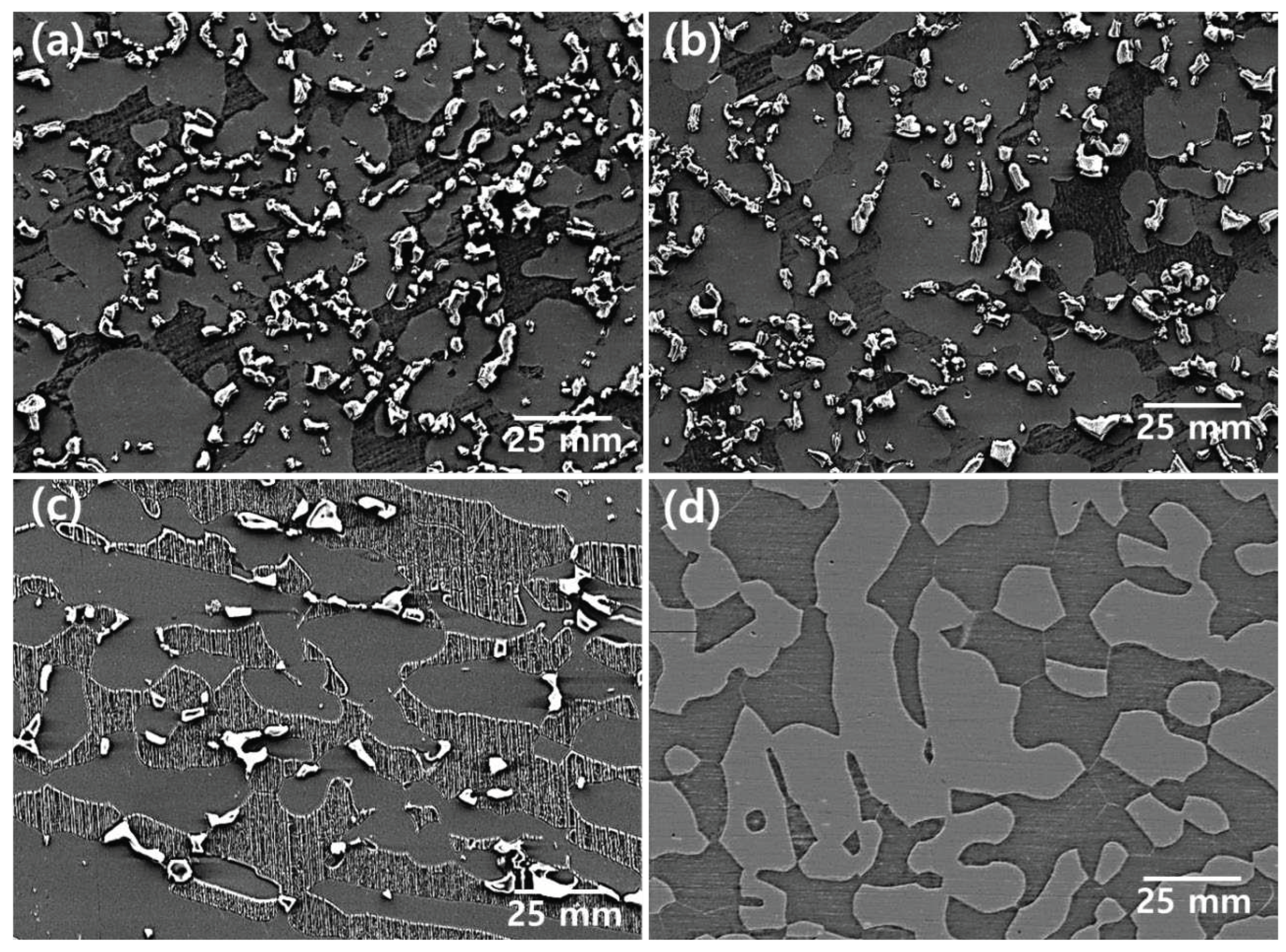
10,
11,
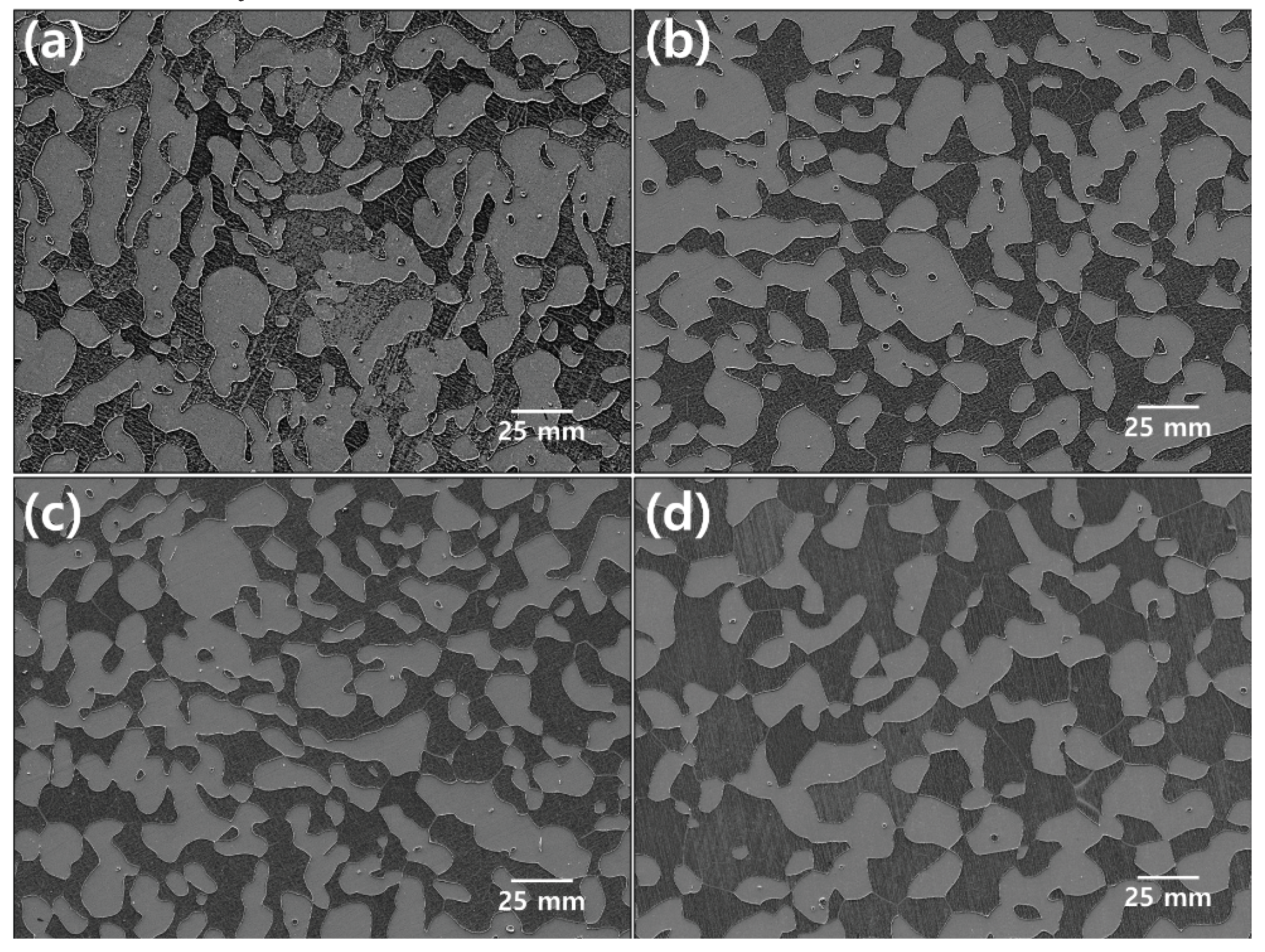
12]. To confirm the secondary phase, heat treatment was performed from 900 to 1050℃. The temperature dependence of the microstructure is shown in
Figure 2 [
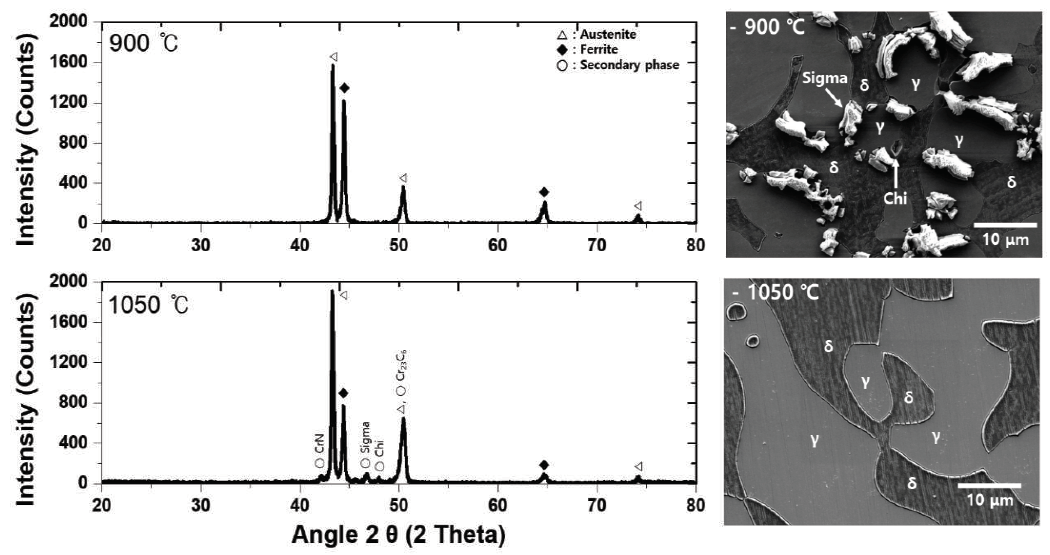
4]. The presence of the secondary phase is confirmed via XRD, as shown in
Figure 3. Most of the secondary phase was identified at 900℃ and formed from 900-1000℃. The secondary phase precipitated at the phase boundary between austenite and ferrite, and EPMA and EDS were used to confirm the chemical composition. The chemical composition of the secondary phase presented in
Figure 4 and
Table 2 indicates that the secondary phase has high Cr and Mo (Sigma) contents and low Cr and Mo contents (Chi) [
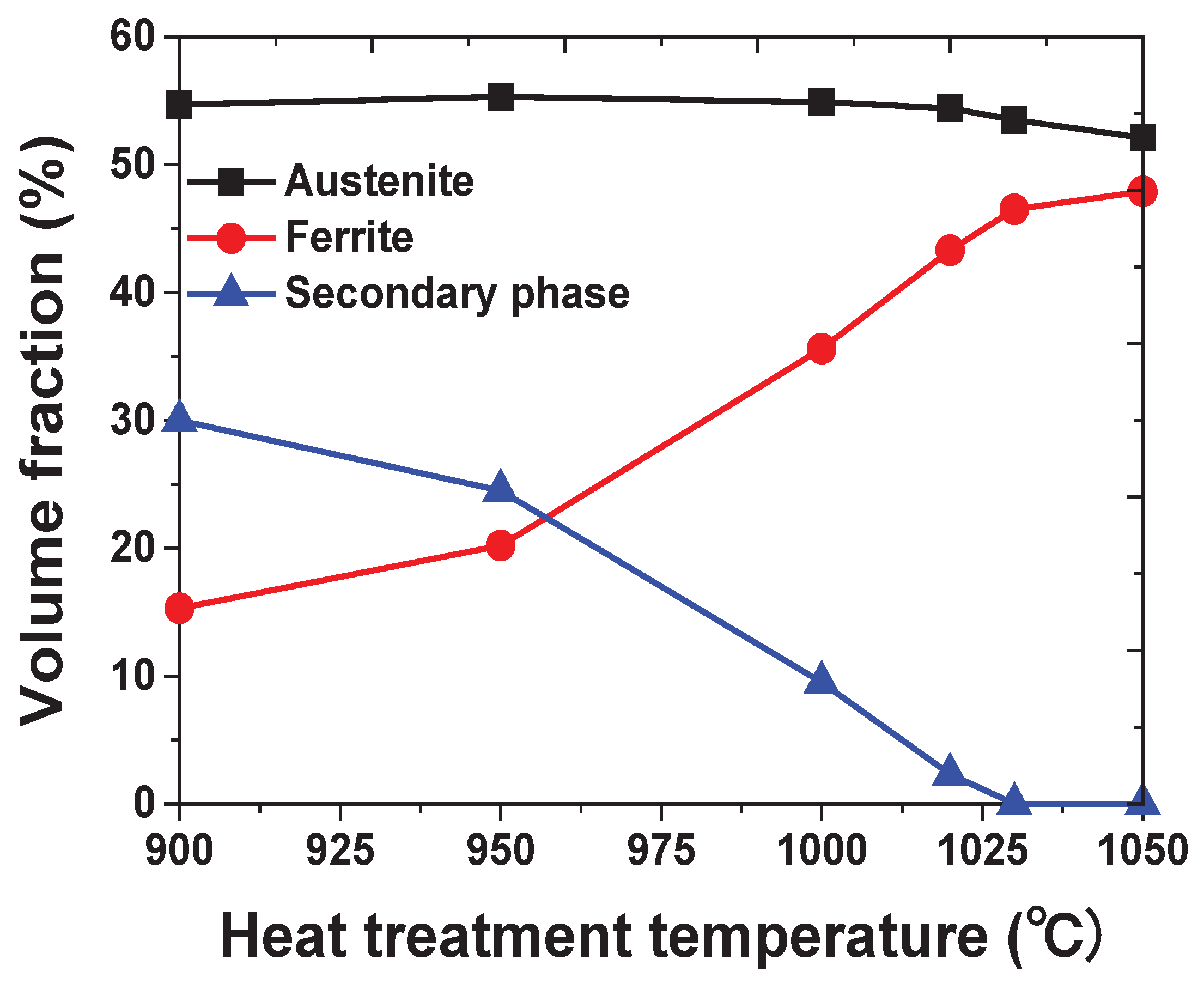
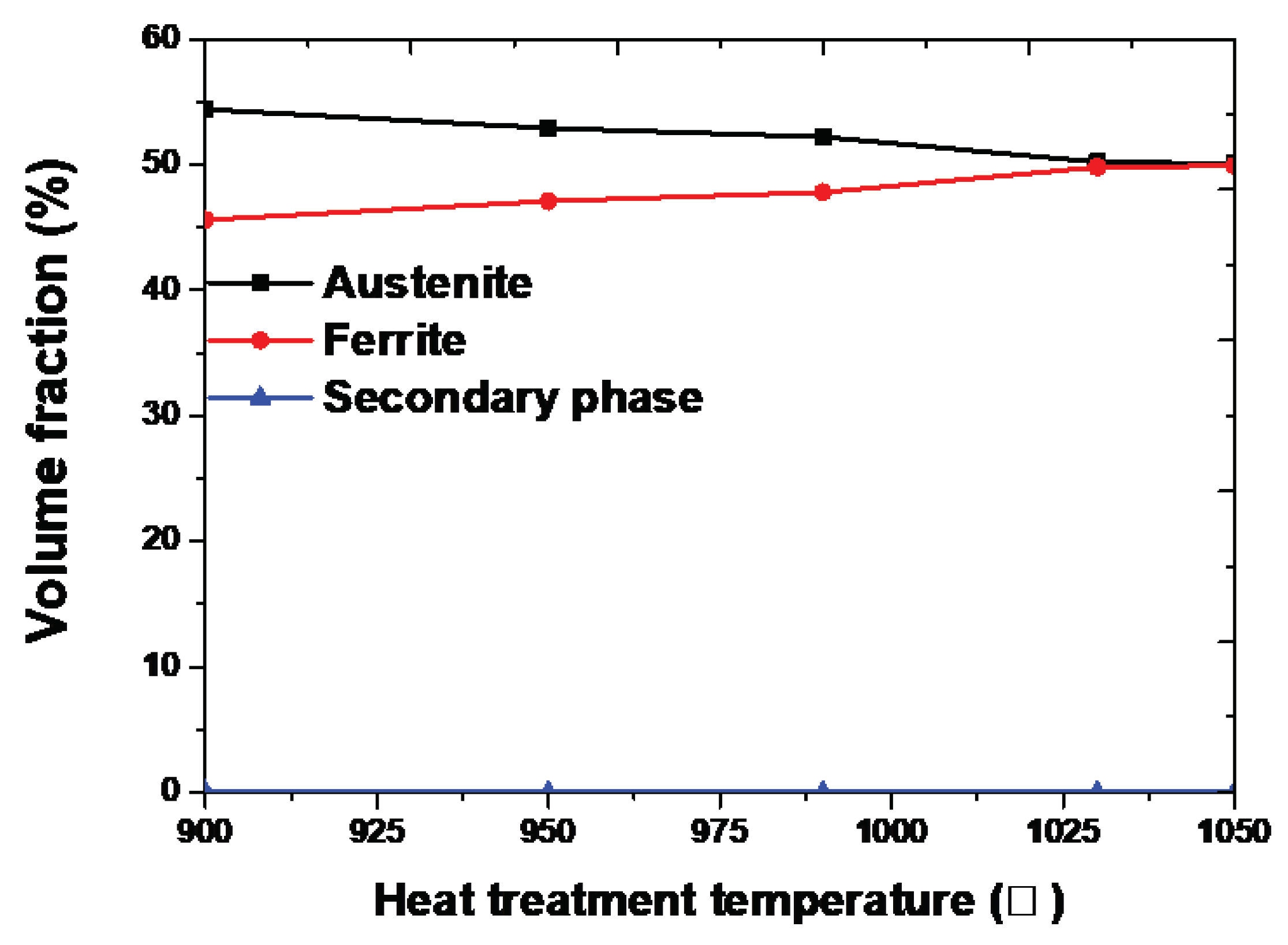
15]. The secondary phase appears as a black and white dot because of the difference in the surface roughness (no etching); the volume fraction of each phase is shown in
Figure 5. The austenite fraction was maintained; however , the ferrite fraction changed based on the fraction of the secondary phase. The Secondayr phase was identified until 1020℃ and could not be identified beyond 1030℃ [
13].
Solution annealing is performed to optimize the corrosion resistance of stainless; for SDSS, this process is generally performed at 1100℃ [
16]. The microstructure and volume fraction after solution annealing are shown in
Figure 7 and
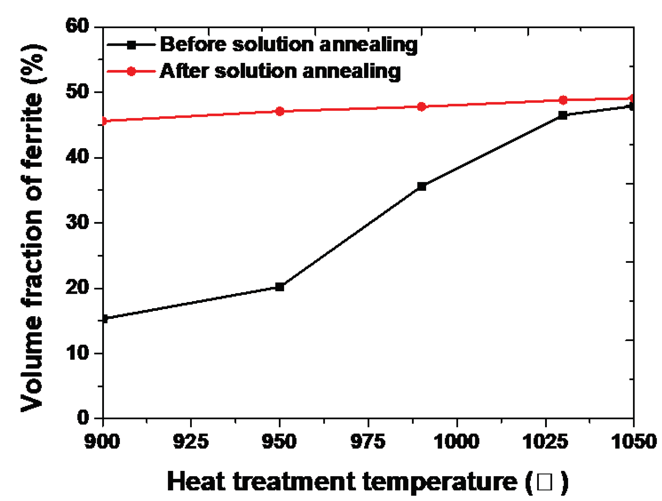
Figure 8, respectively. After solution annealing, the microstructures of the four specimens appear similar; however , differences are observed in the volume fraction. Autenite represents a case of the solution annealing of a specimen with a high volume fraction of the secondary phase [
14]. The secondary phase affected the solution annealing process; this confirmed that the solution of the alloys influenced the volume fraction.
Considering the volume fraction and chemical composition, the secondary phase was formed at the boundary of austenite and transformed into ferrite because of segregation Cr and Mo into ferrite. During solution annealing, the secondary phase transforms into ferrite, as shown
Figure 8. Because high amounts of Cr and Mo in the secondary phase do not dissolve in austenite but readily dissolves in ferrite, the transformation result in ferrite. This difference of volume fraction on austenite and ferrite makes the difference of chemical composition on each phase [
4,
5,
20,
21,
22].
3.2. Electrochemical properties
The potentiodynamic polarization test is used to elucidate the corrosion behavior of a material by measuring the current density with respect to potential [
4,
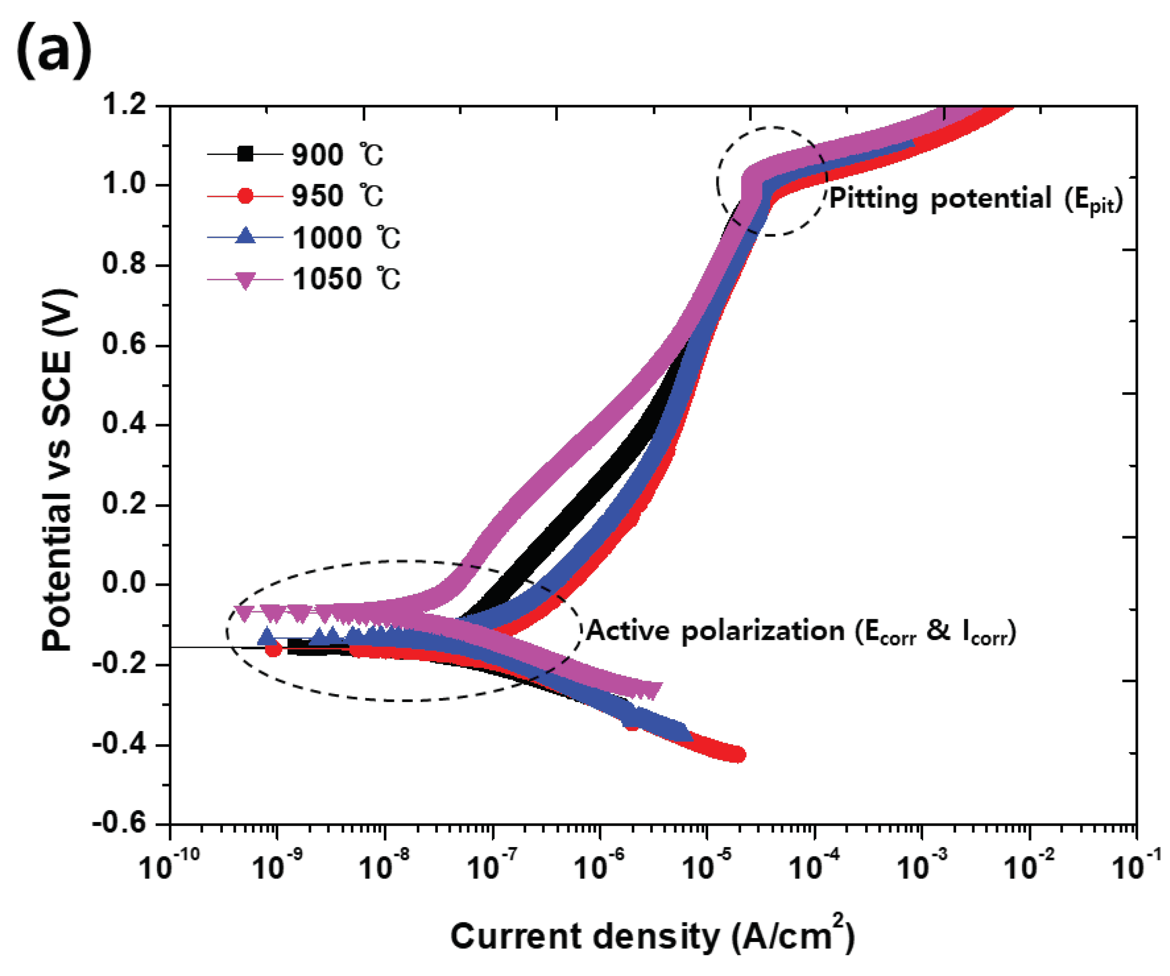
5]. From the potentiodynamic polarization test results shown
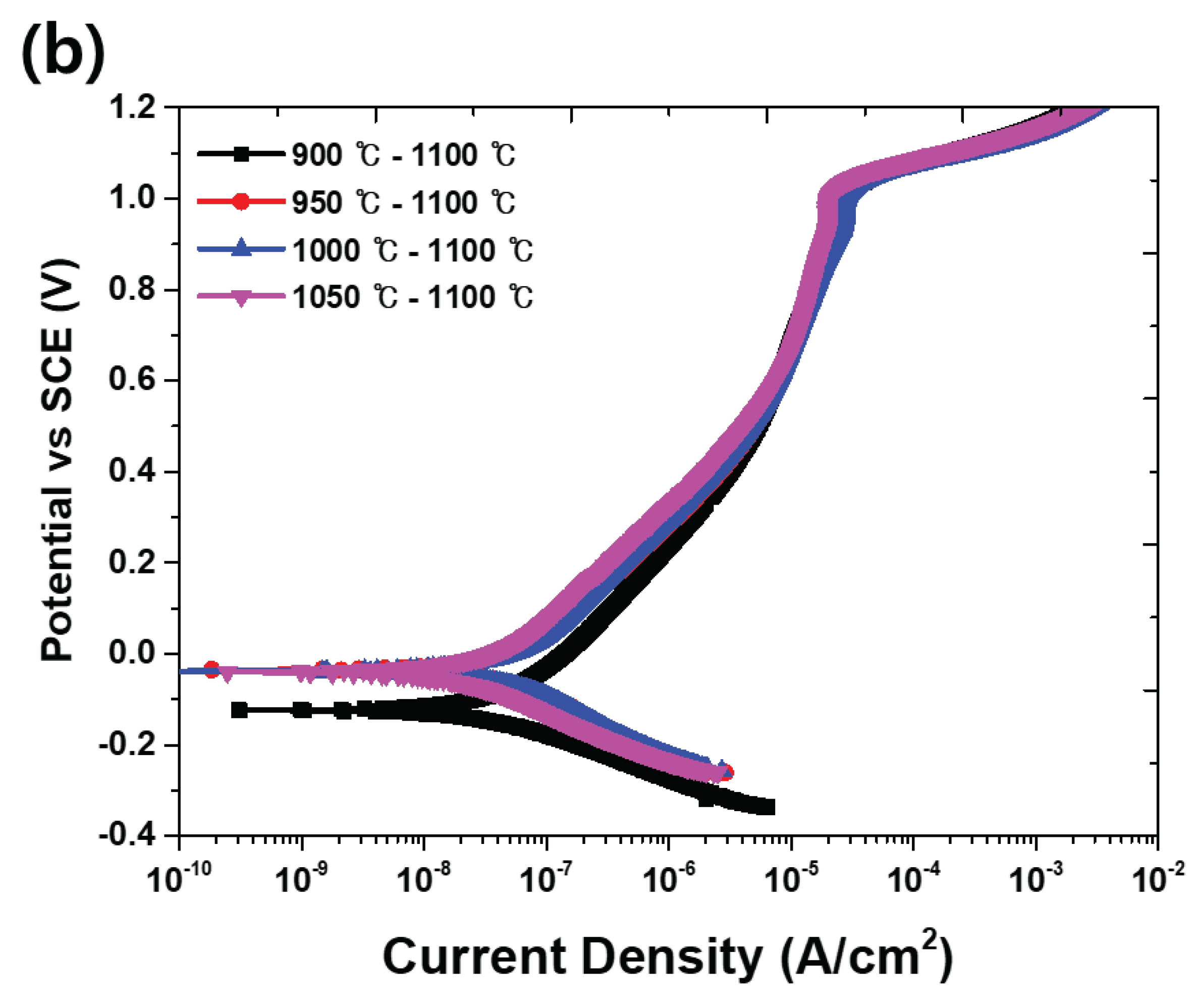
Figure 9 and
Table 6, the presence of the secondary phase decreases the potential (E
corr) and increases the current density (I
corr) in the activation polarization. The results of the potentiodynamic polarization test confirm that the solution annealing increases the corrosion resistance. Solution annealing optimizes the corrosion resistance because it equalizes the pitting resistance (PRE, wt.% Cr + 3.3 wt.% Mo + 16 wt.% N) of austenite and ferrite [
4].
The CPT is used to evaluate the corrosion resistance of duplex stainless steel by comparing the temperature at which the passivation layer is destroyed [
5,
17,
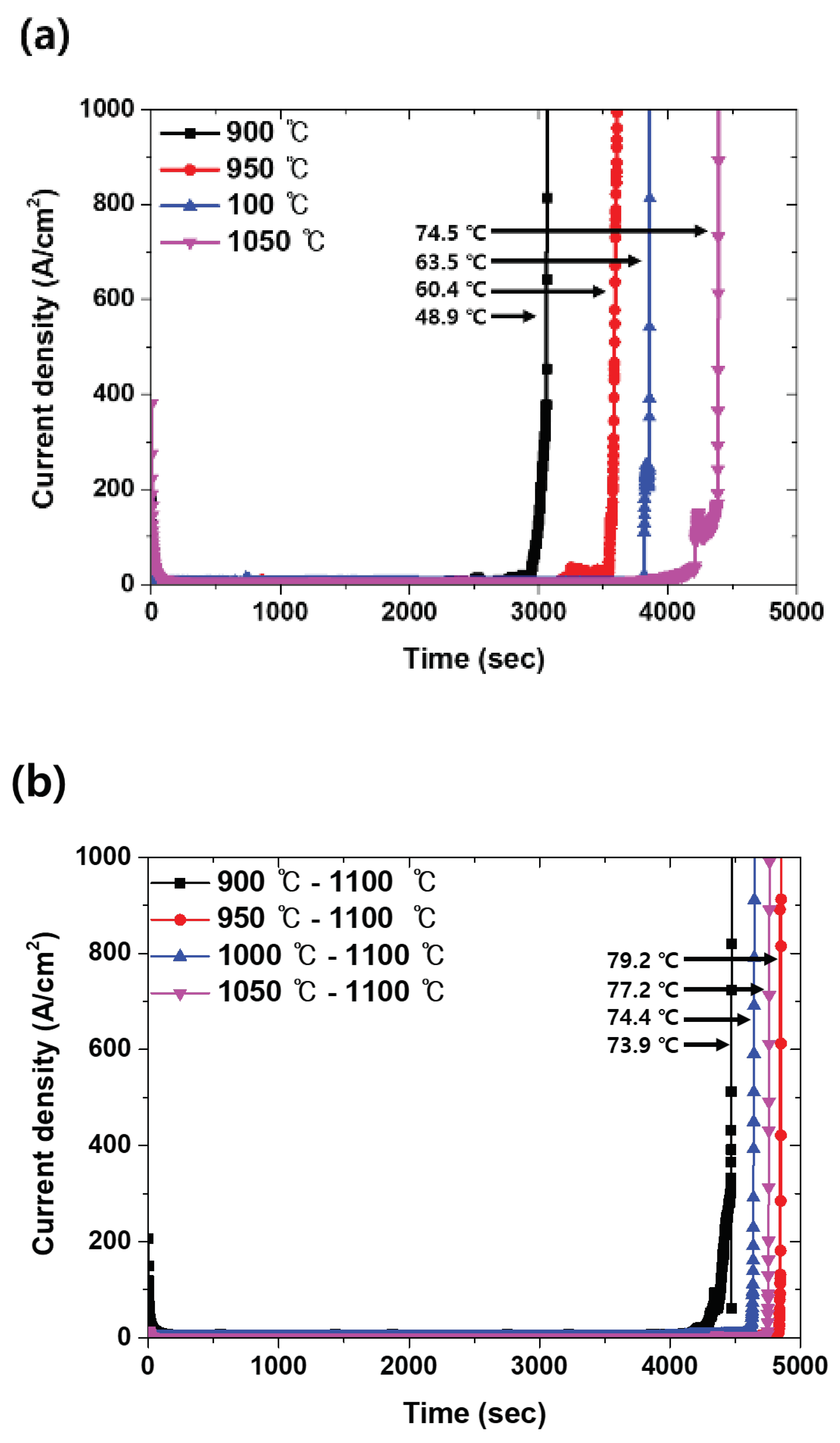
18]. The corrosion resistance was compared considering the volume fraction of the secondary phase, and the results are shown
Figure 10. The secondary phase is a factor that decrease CPT and influences solution annealing [
14]. The CPT test shows a difference in the corrosion resistance with PRE because PRE is calculated using the chemical composition, which is affected by the elements present in each phase [
4]. This relationship is related to the volume fraction, and the fractions of austenite and ferrite that are not equalized by the secondary phase, which affects the chemical composition and corrosion resistance.
Figure 10a shows the effect with volume fraction of secondary phase. The increased volume fraction of secondary phase decreased CPT because the secondary phase is pitting site. Also, solution annealing shows the increased CPT but that was affected of the secondary phase.
Figure 10b shows the effect of secondary phase on solution annealing. CPT shows the secondary phase decreased the effect of solution annealing.
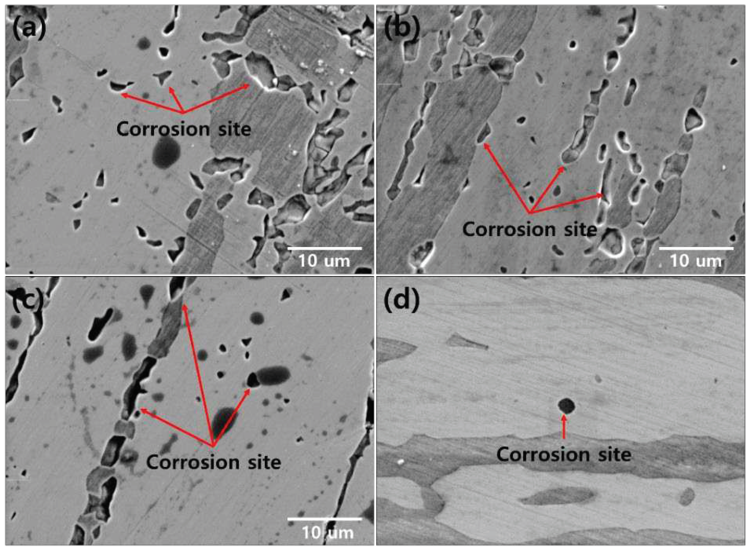
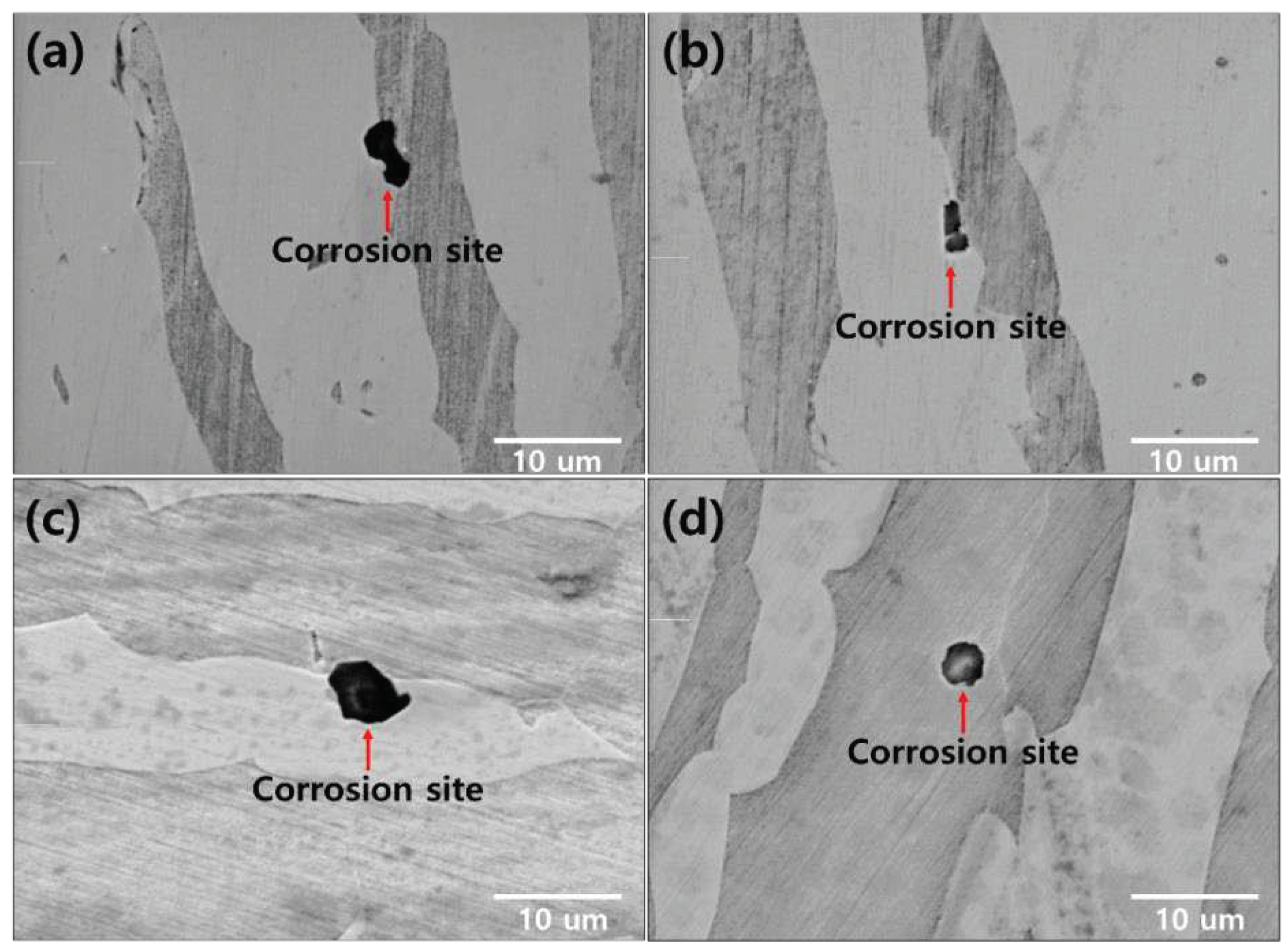
The corrosion morphology was confirmed at the location of the electrochemical characterization analysis, as shown in
Figure 11 and
Figure 12 [
19]. The secondary phase is the corrosion site that causes corrosion in the form of a secondary phase. The pitting after 1050℃ worked on austenite (PRE=41.1) because of low PREN than ferrite (PRE=43.6). The chemical composition at 1050℃ shown in
Table 7. When the volume fraction of austenite to ferrite is equal (1050-1100℃), corrosion occurs at the phase boundary between the austenite and ferrite.
The secondary phase is the corrosion site owing to the decreased corrosion resistance (Chi, 22 wt.% Cr and 2.2 wt.% Mo), resulting in the segregation of the alloy [
21,
22]. To prevent the decrease in the corrosion resistance, solution annealing is performed; however, when a secondary phase is precipitated, the volume fraction cannot be equalized even with solution annealing, and the corrosion resistance cannot be optimized.
4. Discussion
The secondary phase precipitated at the boundary of austenite via the segregation of Cr and Mo. Solution annealing is a heat treatment to optimize the corrosion rsistance [
4,
5,
6]. However, SDSS, in which the secondary phase is precipitated, does not have an optimized corrosion resistance [
10,
11,
12]. The secondary phase is transformed into ferrite, and austenite should be transfromed into ferrite [
16]. However, as a sufficient driving force to realize this transformation does not exist, it remains as austenite. When the fraction of austenite was high, the corrosion resistance decreased becaused of the low corrosion resistance of austenite.
The secondary phase reduced the potential and increased the corrosion rate in the activation polarization of the potentiodynamic polarizaion curve [
4]. After solution annealing, the secondary phase was dissolved in feffire: however, the corrosion resistance was not optimized owing to the difference in the fraction of austenite and ferrite because of variations in the pitting resistance and chemical composition.
Solution annealing improve the corrosion resistance but does not provide a sufficient driving force for dissolving the secondary phase and increasing the ferrite fraction [
16]. Therefore, when the secondary phase is precipitated, the fraction of ferrite must be increased; therefore, heat treatment at a high temperature of up to 1200℃ results in equivalent fractions of austenite and ferrite [
5]. When the secondary phase is precipitated, the solution annealing treatment should be conducted at a temperature higher than the conventional solution annealing temperature (1100℃), and the corrosion resistance can be improved.
5. Conclusions
By simulating the microstructure of SDSS2507, the secondary phase fraction was precipitated by controlling these three types. Solution annealing was performed to solidify the secondary phase, and the following conclusions were drawn after analyzing the electrochemical properties using potentiodynamic polarization and CPT analysis.
- 1)
The secondary phase precipitated at the austenite boundary and grew into ferrite because of the high Cr and Mo content. After solution annealing at 1100℃, the secondary phase dissolved as ferrite. Solution annealing optimized the corrosion resistance by rendering the fraction of austenite and ferrite as 5:5; however, solution annealing after the precipitation of the secondary phased did not result in a phase fraction of 5:5.
- 2)
The secondary phase is formed by the segregation of Cr and Mo, which reduces the corrosion resistance, ad confirmed by the potentiodynamic polarization and CPT analysis. The solution annealing after the precipitation of secondary phase fully dissolved the secondary phase but did not result in the growth of ferrite or optimization of the corrosion resistance. To improve the corrosion resistance by the dissolution of the secondary phase and growth of ferrite, solution annealing after precipitation of the secondary phase should be performed at a higher temperature than the conventional temperature (1100℃).
- 3)
SDSS2507 is a manufactured by high temperature forging because it is used in valves and pipes in offshore plants. However, owing to the difference in the cooling rate between the inside and outside, a secondary phase is formed inside, and hot cracks occur. To stabilize the microstructure and improve the corrosion resistance, the solution annealing of SDSS2507 at a temperature higher than that of the solution heat treatment can prevent high-temperature cracking.
Acknowledgments
This study was supported by a National Research Foundation of Korea (NRF) grant funded by the Korean Government (MSIT) [grant number 2020R1A5A8018822]; a Korea Institute for Advancement of Technology (KIAT) grant funded by the Korean Government (MOTIE) (P20002019, Human Resource Development Program for Industrial Innovation); and the BK21 FOUR program [grant number 4120200513801] funded by the Ministry of Education (MOE, Korea) and the National Research Foundation of Korea (NRF).
References
- Campbell, D.; Ramsay, H. Moller. G.; Watt, C. Observation on foods of kiore (Rattus exulans) found in husking stations on northern offshore islands of New Zealand. N. Z. J. Ecol. 1984, 7, 131–138. [Google Scholar]
- Park, J.; Kim, M.; Woo, J. A Study on Process Management Method of Offshore Plant Piping Material using Process Mining Technique. J. Soc. Nav. Arch. Korea 2019, 56, 143–151. [Google Scholar] [CrossRef]
- Kaldellis, J.; Apostolou, D. Life cycle energy and carbon footprint of offshore wind energy. Comparison with onshore counterpart. Renew. Energy 2017, 108, 72–84. [Google Scholar] [CrossRef]
- Nilsson, J. O. Super duplex stainless steels. Mater. Sci. Technol. 1992, 8, 685–700. [Google Scholar] [CrossRef]
- Shin, B.-H.; Park, J.; Jeon, J.; Heo, S.-B.; Chung, W. Effect of cooling rate after heat treatment on pitting corrosion of super duplex stainless steel UNS S 32750. Anti-Corrosion Methods Mater. 2018, 65, 492–498. [Google Scholar] [CrossRef]
- Kosea, C. Topalb, C. Texture, microstructure and mechanical properties of laser beam welded AISI 2507 super duplex stainless steel. Matter. Chem. Phys 2022, 289, 126490. [Google Scholar] [CrossRef]
- Iacoviello, F.; Di Cocco, V.; Franzese, E.; Natali, S. High temperature embrittled duplex stainless steels: influence of the chemical composition on the fatigue crack propagation. Procedia Struct. Integr. 2017, 3, 308–315. [Google Scholar] [CrossRef]
- Ha, H.-Y.; Jo, H.-H.; Lee, J.; Kim, S.-D.; Moon, J.; Jang, J.H.; Lee, T.-H.; Lee, C.-H. Effect of combined addition of N and C on high-temperature deformation behavior of UNS S32101 type lean duplex stainless steels. Mater. Today Commun. 2021, 29, 102749. [Google Scholar] [CrossRef]
- Westin, E.M.; Putz, A.; Maderthoner, A.; Pilhagen, J. Solidification cracking in duplex stainless steel flux-cored arc welds Part 1—cracking in 30-mm-thick material welded under high restraint. Weld. World 2022, 66, 2405–2423. [Google Scholar] [CrossRef]
- Tahchieva, A.; Chatterjee, D.; Helvoort, A.; Isern, N.; Cabrera, J. Effect of the nano structuring by high-pressure torsion process on the secondary phase precipitation in UNS S32750 Superduplex stainless steel. Mater. Charact. 2022, 183, 111639. [Google Scholar] [CrossRef]
- Kalandyk, B.; Zapala, R.; Palka, P. Effect of Isothermal Holding at 750℃ and 900℃ on Microstructure and Properties of Cast Duplex Stainlesss Steel Containg 24%Cr-5%Ni-2. 5%Mo-2.5%Cu. Materials 2022, 15, 8569. [Google Scholar] [CrossRef] [PubMed]
- Assumpcao, R.; Ferreira, M.; Sousa, M.; Santos, D.; Sicupira, D. Effect of strain-induced martensite reverse transformation on microstructure evolution and electrochemical behavior of 2304 lean duplex stainless steel. Corros. Eng. Sci. Technol. 2022, 57, 499–508. [Google Scholar] [CrossRef]
- Shin, B.; Kim, D. Park, S. ; Hwang, H.; Park, J.; Chung, W. Precipitation condition and effect of volume fraction on corrosion properties of secondary phase on casted super-duplex stainless steel UNS S32750. Anti-Corros. Methods Mater. 2018, 66, 61–66. [Google Scholar] [CrossRef]
- Sung, C.; Shin, B.-H.; Chung, W. Effect of Solution Annealing on Austenite Morphology and Pitting Corrosion of Super Duplex Stainless Steel UNS S 32750. Int. J. Electrochem. Sci. 2021, 16, 210813. [Google Scholar] [CrossRef]
- Calliari, I.; Brunelli, K.; Dabalà, M.; Ramous, E. Measuring secondary phases in duplex stainless steels. J. Miner. Met. Mater. Soc. 2009, 61, 80–83. [Google Scholar] [CrossRef]
- Torres, C.; Johnsen, R.; Iannuzzi, M. Crevice corrosion of solution annealed 25Cr duplex stainless steels: Effect of W on critical temperatures. Corros. Sci. 2020, 178, 109053. [Google Scholar] [CrossRef]
- Yoon, B.; Ahn, Y. Effect of Aging on Pitting Corrosion Resistance of 21Cr Lean Duplex Stainless Steel with Different Molybdenum Contents. J. Mater. Eng. Perform. 2022. [CrossRef]
- Barros, T.S.; Pecly, P.H.R.; Pardal, J.M.; Gonzaga, A.C.; Tavares, S.S.M. Comparison Between Hot Rolled and Powder Metallurgy–Hot Isostatic Pressing (PM-HIP) Processed Duplex Stainless Steel UNS S32205. J. Mater. Eng. Perform. 2022, 31, 5504–5510. [Google Scholar] [CrossRef]
- Laleh, M.; Haghdadi, N.; Hughes, A.; Primig, S.; Tan, E. Enhancing the repassivation ability and localized corrosion resistance of an additively manufactured duplex stainless steel by post-proceeding heat treatment. Corr. Sci. 2023, 198, 110106. [Google Scholar] [CrossRef]
- Andrade, R.A.; Magnabosco, R. Computational Simulation of Duplex Stainless Steel Continuous Cooling Transformation Curves Using DICTRA®. Mater. Res. 2022, 25. [Google Scholar] [CrossRef]
- Magnabosco, R.; Costa Morias, L.; Santos, D. Use of composition profiles near sigma phase for assessment of localized corrosion resistance in a duplex stainless steel. Calphad. 2019, 64, 126–130. [Google Scholar] [CrossRef]
- Costa Morias, L.; Magnabosco, R. Experimental investigations and DICTRA simulation of sigma phase formation in a duplex stainless steel. Calphad. 2017, 58, 214–218. [Google Scholar] [CrossRef]
Figure 1.
Heat-treatment conditions for examining the precipitation of the secondary phase and the effect of solution annealing.
Figure 1.
Heat-treatment conditions for examining the precipitation of the secondary phase and the effect of solution annealing.
Figure 2.
SEM images after heat treatment for the precipitation of the secondary phase of SDSS UNS S32750: (a)900℃, (b)950℃, (c)1000℃, and (d)1050℃.
Figure 2.
SEM images after heat treatment for the precipitation of the secondary phase of SDSS UNS S32750: (a)900℃, (b)950℃, (c)1000℃, and (d)1050℃.
Figure 3.
XRD patterns with and without the secondary phase (900 and 1050℃) of SDSS UNS S32750.
Figure 3.
XRD patterns with and without the secondary phase (900 and 1050℃) of SDSS UNS S32750.
Figure 4.
EPMA images after the precipitation of the secondary phase after heat treatment at 900℃ of SDSS UNS S32750.
Figure 4.
EPMA images after the precipitation of the secondary phase after heat treatment at 900℃ of SDSS UNS S32750.
Figure 5.
Volume fraction of each phase with respect to the heat-treatment temperature of SDSS UNS S32750.
Figure 5.
Volume fraction of each phase with respect to the heat-treatment temperature of SDSS UNS S32750.
Figure 6.
SEM images after solution annealing at 1100℃ with the volume fraction of the secondary phase of SDSS UNS S32750: (a)900-1100℃, (b)950-1100℃, (c)1000-1100℃, and (d)1050-1100℃.
Figure 6.
SEM images after solution annealing at 1100℃ with the volume fraction of the secondary phase of SDSS UNS S32750: (a)900-1100℃, (b)950-1100℃, (c)1000-1100℃, and (d)1050-1100℃.
Figure 7.
Volume fraction after solution annealing at 1100℃ with volume fraction of secondary phase of SDSS UNS S32750.
Figure 7.
Volume fraction after solution annealing at 1100℃ with volume fraction of secondary phase of SDSS UNS S32750.
Figure 8.
Volume fraction with or without solution annealing at 1100℃ of SDSS UNS S32750.
Figure 8.
Volume fraction with or without solution annealing at 1100℃ of SDSS UNS S32750.
Figure 9.
Potentiodynamic polarization curve-potential vs. current density curve in the electrolyte comprising 3.5 wt.% NaCl of SDSS UNS S32750: (a) Before solution annealing, and (b) after solution annealing.
Figure 9.
Potentiodynamic polarization curve-potential vs. current density curve in the electrolyte comprising 3.5 wt.% NaCl of SDSS UNS S32750: (a) Before solution annealing, and (b) after solution annealing.
Figure 10.
CPT curve-time(s) vs. current density (A/cm2), with the heat-treatment condition of SDSS UNS S32750: (a) Before and (b) after solution annealing
Figure 10.
CPT curve-time(s) vs. current density (A/cm2), with the heat-treatment condition of SDSS UNS S32750: (a) Before and (b) after solution annealing
Figure 11.
Corrosion morphology with the heat-treatment temperature for the precipitation of the secondary phase of SDSS UNS S32750: (a) 900℃, (b) 950℃, (c) 1000℃, and (d) 1050℃
Figure 11.
Corrosion morphology with the heat-treatment temperature for the precipitation of the secondary phase of SDSS UNS S32750: (a) 900℃, (b) 950℃, (c) 1000℃, and (d) 1050℃
Figure 12.
Corrosion morphology after the solution annealing of SDSS UNS S3275: (a) 900-1100℃, (b) 950-1100℃, (c) 1000-1100℃, and (d) 1050-1100℃
Figure 12.
Corrosion morphology after the solution annealing of SDSS UNS S3275: (a) 900-1100℃, (b) 950-1100℃, (c) 1000-1100℃, and (d) 1050-1100℃
Table 1.
Chemical composition of casted SDSS UNS S32750.
Table 1.
Chemical composition of casted SDSS UNS S32750.
| |
C |
N |
Mn |
Ni |
Cr |
Mo |
Fe |
PRE |
| SDSS2507 |
0.01 |
0.3 |
0.79 |
6.8 |
25.0 |
3.8 |
Bal |
42 |
Table 2.
Chemical composition of the secondary phase (Sigma & Chi) after heat treatment at 900℃ of SDSS UNS S32750.
Table 2.
Chemical composition of the secondary phase (Sigma & Chi) after heat treatment at 900℃ of SDSS UNS S32750.
| Chemical composition (wt.%) |
Sigma |
Chi |
| Cr |
30.1 ± 2.1 |
22.1 ± 1.5 |
| Mo |
8.8 ± 0.6 |
2.2 ± 0.1 |
| Ni |
4.6 ± 0.4 |
9.5 ± 0.3 |
| Mn |
1.1 ± 0.1 |
1.0 ± 0.1 |
| Fe |
Bal |
Bal |
Table 6.
Major value in potentiodynamic polarization cure (
Figure 9) with heat treatment conditions of super duplex stainless steel UNS S32750.
Table 6.
Major value in potentiodynamic polarization cure (
Figure 9) with heat treatment conditions of super duplex stainless steel UNS S32750.
| |
(a) |
(b) |
| |
Ecorr(mV) |
Icorr(A/cm2) |
EPit(mV) |
Ecorr(mV) |
Icorr(A/cm2) |
EPit(mV) |
| 900℃ |
-150 ± 10 |
9 x 10⁻⁷ |
990 ± 10 |
-100 ± 5 |
1 x 10⁻⁷
|
1020 ± 10 |
| 950℃ |
-150 ± 10 |
9 x 10⁻⁷
|
1000 ± 10 |
-40 ± 5 |
1 x 10⁻⁷
|
1020 ± 10 |
| 1000℃ |
-140 ± 10 |
8 x 10⁻⁷
|
1010 ± 10 |
-40 ± 5 |
1 x 10⁻⁷
|
1020 ± 10 |
| 1050℃ |
-80 ± 10 |
2 x 10⁻⁷
|
1030 ± 10 |
-40 ± 5 |
1 x 10⁻⁷
|
1030 ± 10 |
Table 7.
Chemical composition of austenite and ferrite after heat treatment at 1050℃ of super duplex stainless steel UNS S32750
Table 7.
Chemical composition of austenite and ferrite after heat treatment at 1050℃ of super duplex stainless steel UNS S32750
| Phase |
Austenite (%) |
Ferrite (%) |
| Chemical Composition |
Cr |
Mo |
N |
Fe |
Cr |
Mo |
N |
Fe |
| 23.2 |
3.1 |
0.48 |
Bal |
26.3 |
5.0 |
0.05 |
Bal |
|
Disclaimer/Publisher’s Note: The statements, opinions and data contained in all publications are solely those of the individual author(s) and contributor(s) and not of MDPI and/or the editor(s). MDPI and/or the editor(s) disclaim responsibility for any injury to people or property resulting from any ideas, methods, instructions or products referred to in the content. |
© 2023 by the authors. Licensee MDPI, Basel, Switzerland. This article is an open access article distributed under the terms and conditions of the Creative Commons Attribution (CC BY) license (https://creativecommons.org/licenses/by/4.0/).
