1. Introduction
In recent years, many engineering studies have drawn researchers' attention to investigate the mechanical behaviour of viscoelastic porous materials [
1,
2,
3,
4,
5,
6] due to the positive results obtained in applied science, engineering, and technological applications such as biology, biophysics, biomechanics, geotechnical engineering, reservoir geomechanics, mining and petroleum engineering, geothermal engineering, thermal insulation, and lightweight structural design. Some researchers have investigated the effects of magnetic field [
7], initial stress [
8], rotation and gravity [
9] on the generalized thermo-viscoelastic diffusion medium. Also, the effects of initial stress and temperature-dependent on the thermo-microstretch elastic solid have been investigated with dual-phase-lag model [
10]. Xu et al. [
11] studied the effects of viscoelastic dampers with high energy dissipation based on an acrylate rubber matrix. Because analytical solutions to the current situation are extremely difficult to achieve, numerical methods have emerged as the primary tool for resolving these problems such as Pei et al. [
12], Ooi et al. [
13], Zhou et al. [
14], Ng et al. [
15], Majchrzak and Turchan [
16], Bottauscio et al. [
17], Deng and Liu [
18] and Partridge and Wrobel [
19]. The concept of treating biological tissue as a porous medium has been deemed more acceptable for incorporating blood flow through arteries implanted in the tissue. One of the computational strategies used to solve the bioheat transfer problems of biological tissues [
20,
21,
22] is the boundary element method (BEM) [
23,
24,
25,
26,
27,
28,
29,
30,
31]. For physical and technological problems, Laplace-domain fundamental solutions are generally easier to get than time-domain fundamental solutions [
32,
33]. As a result, because it requires the Laplace-domain fundamental solutions of the problem's governing equations, the CQBEM is highly useful for problems that did not have time-domain fundamental solutions. As a result, CQBEM broadens the spectrum of engineering problems that can be tackled using traditional time-domain BEM.
The primary goal of this paper is to present a new boundary element model for explaining thermomechanical interactions in three-temperature anisotropic viscoelastic porous media. The uncoupled governing equations are solved independently, where the bioheat equation is solved first using the GBEM based on LRBFCM to obtain the temperature distribution, and then the mechanical equation was solved using the CQBEM to obtain the displacements and stresses. The resulting linear systems have been solved by communication-avoiding Arnoldi (CA-Arnoldi) preconditioner which reduces the number of iterations and the total CPU time. The numerical results demonstrate the validity, efficiency and accuracy of the proposed model
2. Formulation of the Problem
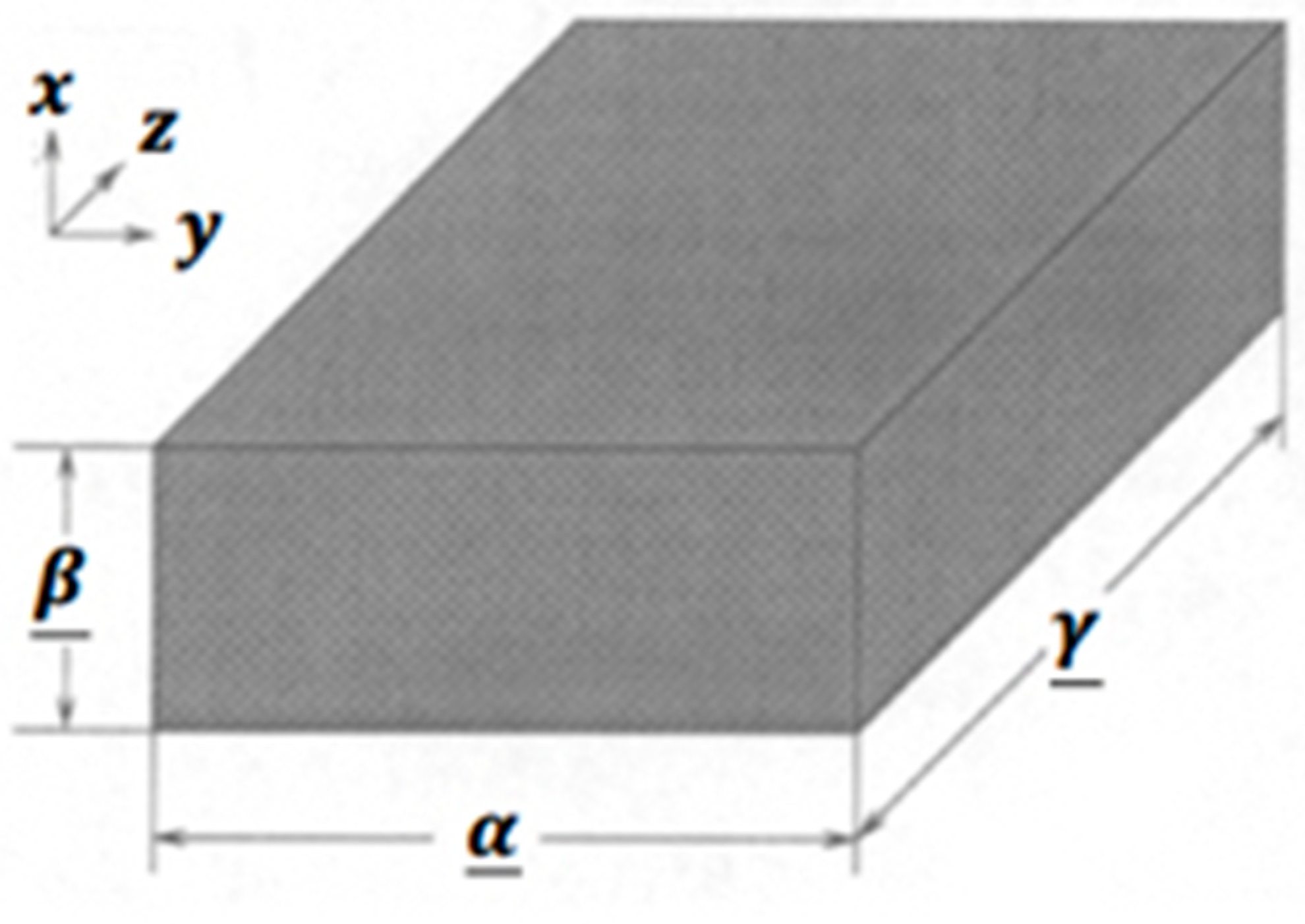
In the Cartesian system
, we consider a region
with a boundary
occupied by an anisotropic viscoelastic porous media as shown in
Figure 1.
According to Biot’s model [
34] and Darcy’s law [
35], the thermo-poroelastic governing equations can be expressed as
On the basis of Bonnet [
36], the governing equations can be written as follows [
37]
in which where the operator
and the tractions
are defined as
According to Fahmy [
30], the thermomechanical interactions can be found by treating the soft tissue as a thermoporoelastic medium and implementing BEM for solving the governing equations (1) and (7).
The three-temperature radiative diffusion equations are as follows
in which
where
denote electron, ion, and phonon, respectively.
3. Boundary Element Implementation for the Temperature Field
The two-dimensions (2D) three-temperature (3T) radiation diffusion equations (9a) – (9c) can be written as
In which .
The total energy per unit mass is as follows
The conditions under consideration can be summarized as follows:
Using the fundamental solution to the following differential equation
The dual reciprocity boundary integral equation corresponding to (10) can be expressed as in Fahmy [
17] as follows
which can be expressed as follows
We assume that the temperature derivative in (17) is approximated as
Thus, from Equation (17), we obtain
where
and
where
are defined as
By using equations (20) and (22), we get
where
with
Now, we introduce the following functions
where
,
.
By differentiating (28), we get
Substitution of Equations (31) - (33) into Equation (27), yields
which can be written as
To solve the resulting linear algebraic systems, the symmetric successive over-relaxation (SSOR) method without matrix inversion [
38] was efficiently implemented.
4. Boundary Element Implementation for the Poroelastic Fields
The representation formula for problem (7) is as follows:
where the integral operators are
In the Laplace domain, the fundamental solution and associated traction are denoted as [
9]
The fundamental solution can be expressed as [
35]
where
Equation (37) can be expressed as
The fundamental solution can be expressed as
in which
Furthermore, the remaining components of the fundamental solution might be stated as
Now, we apply the following limiting
to (34) to obtain
In addition, we apply the following limiting method to (35) to obtain [
39]
in which
and
By using equations (45) - (48), the boundary integral equation in Laplace domain can be expressed as
The poroelastodynamic boundary integral equation can be expressed using the inverse Laplace transformation as
The fundamental solution is as follows [
37]
The Stokes theorem states that the differentiable vector field
,
can be represented as
where
We can use (53) to obtain the following formula
According to [
40], we obtain
By using (40) and (51), we obtain
According to [
37], we get
which can be expressed using (40) as
Using (35) and (59), we obtain
The second term of the integral (61) can be expressed as
where
Based on [
37], the following limit may be rewritten as
By augmenting
to
and employing (56) we can write (61) as
By dividing the time interval
, we obtain the following integral
According to Lubich formula [
41,
42], the integration weights
can be determined as
Using
, the integral equation (68) may be approximated as
By plugging Equation (69) into Equation (67), we get
with
Based on [
39], we get
that can be expressed in Laplace domain as follows
The discretization of the boundary
into
boundary elements
leads to
Now, we use
continuous functions
and
discontinuous functions
to define the following subspaces
By using (75) and (76), the unknown datum can be approximated as follows
5. Numerical Results and Discussion
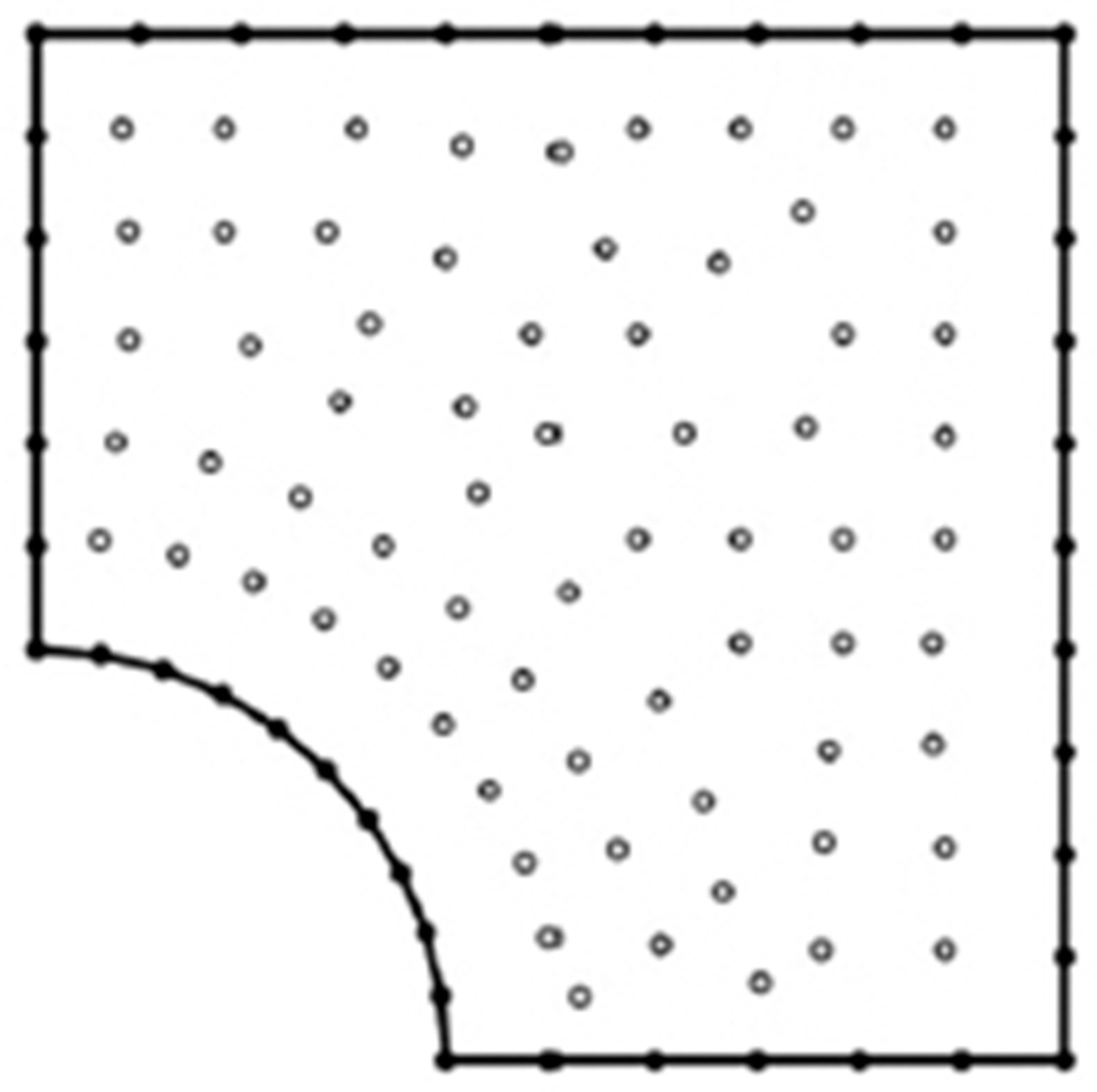
In the context of analyzing the BEM model results of solving ultrasonic wave propagation problems in three-temperature anisotropic viscoelastic porous media. As shown in
Figure 2, the BEM discretization was carried out with 42 boundary elements and 68 internal points.
To demonstrate the numerical results obtained by the proposed technique, the following physical parameters were used:
For anisotropic viscoelastic porous media, we considered the following physical parameters [
43]
and therefore
and
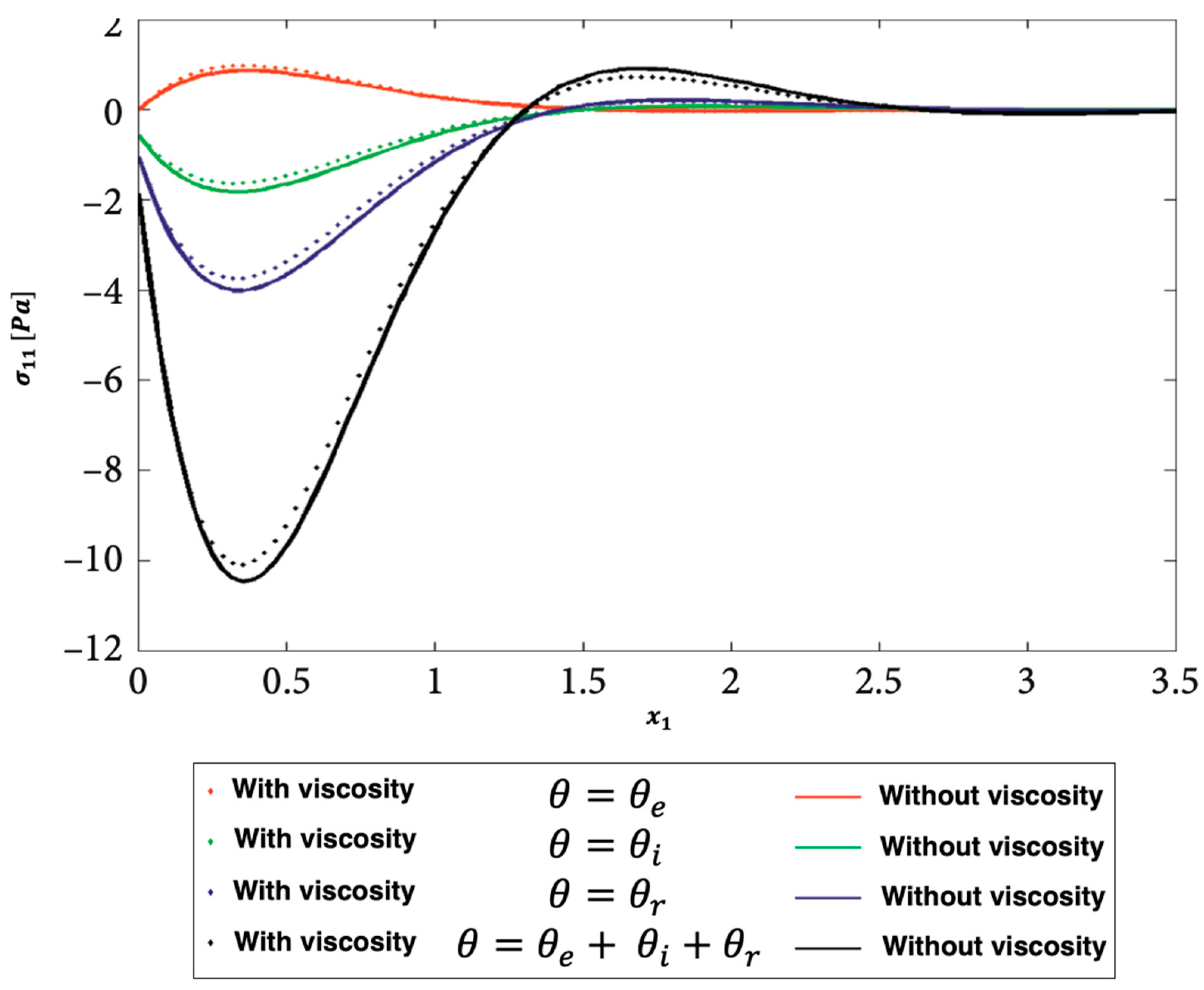
Figure 3,
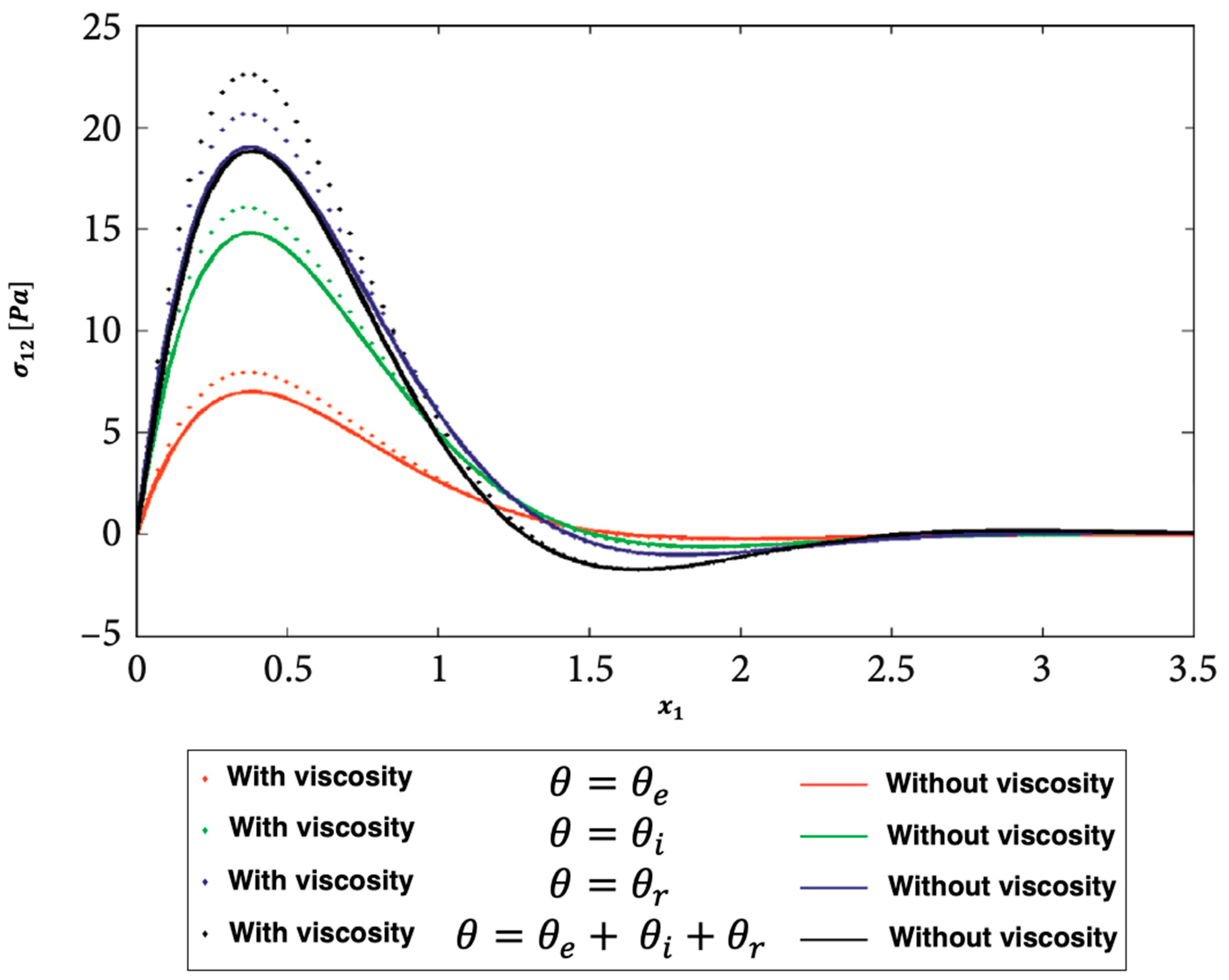
Figure 4 and
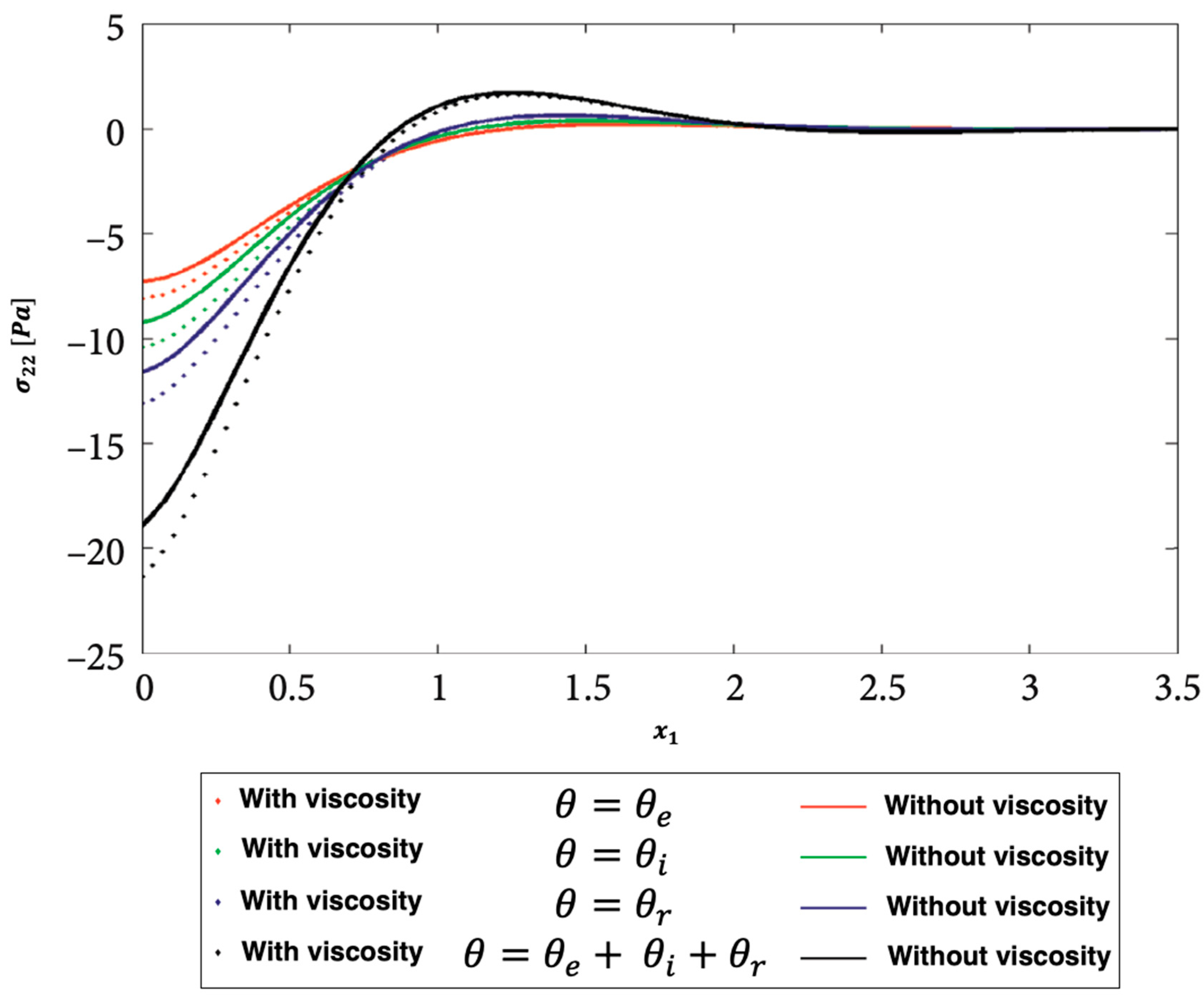
Figure 5 show the distributions of the nonlinear thermal stress
waves along
-axis for electron, ion, phonon and total 3T with and without viscosity effect.
Figure 3 shows the distribution of the nonlinear thermal stress
waves for electron (
), ion (
), phonon (
), and total 3T (
) with and without viscosity effect.
Figure 4 shows the distribution of the nonlinear thermal stress
waves for electron (
), ion (
), phonon (
), and total (
) with and without viscosity effect.
Figure 5 shows the distribution of the nonlinear thermal stress
waves for electron (
), ion (
), phonon (
), and total (
) with and without viscosity effect.
Figure 6,
Figure 7 and
Figure 8 show the distributions of the nonlinear thermal stress
waves along
-axis for electron, ion, phonon and total 3T for isotropic and anisotropic viscoelastic porous structures.
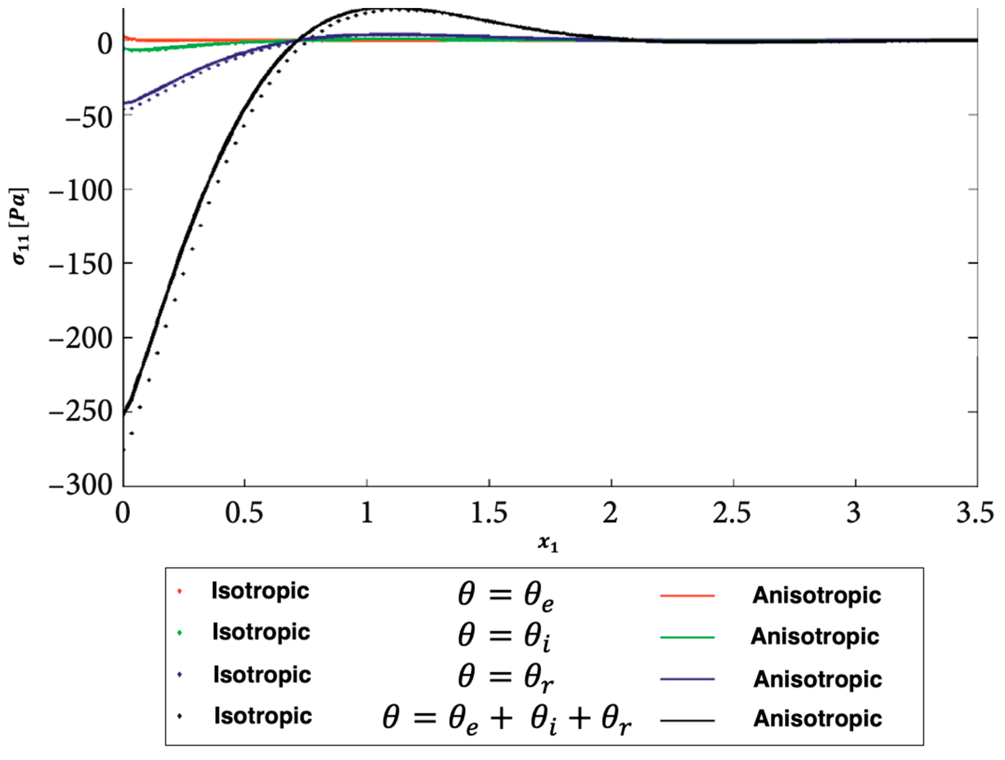
Figure 6 shows the distribution of the nonlinear thermal stress
waves for electron (
), ion (
), phonon (
), and total (
) for isotropic and anisotropic viscoelastic porous structures.
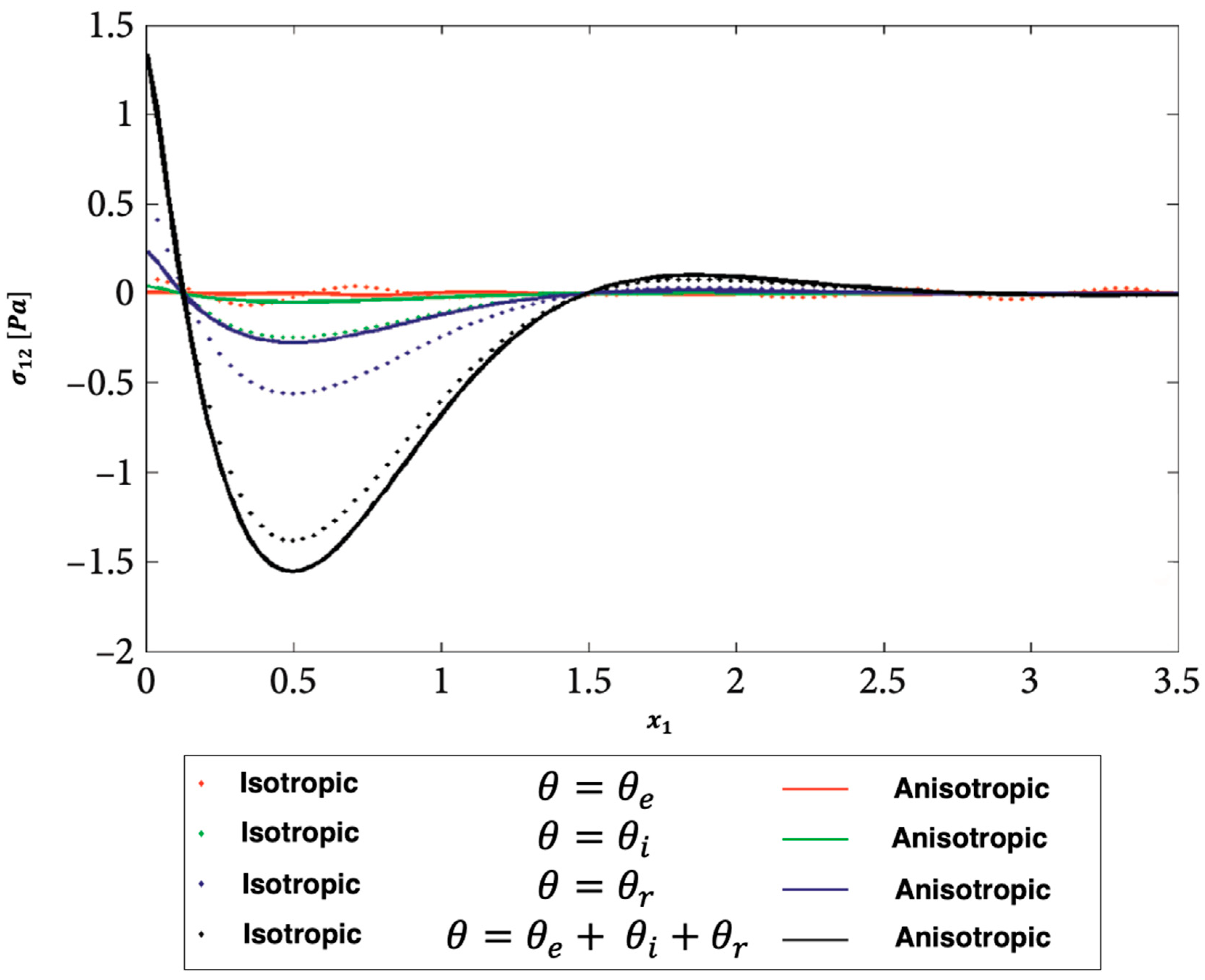
Figure 7 shows the distribution of the nonlinear thermal stress
waves for electron (
), ion (
), phonon (
), and total (
) for isotropic and anisotropic viscoelastic porous structures.
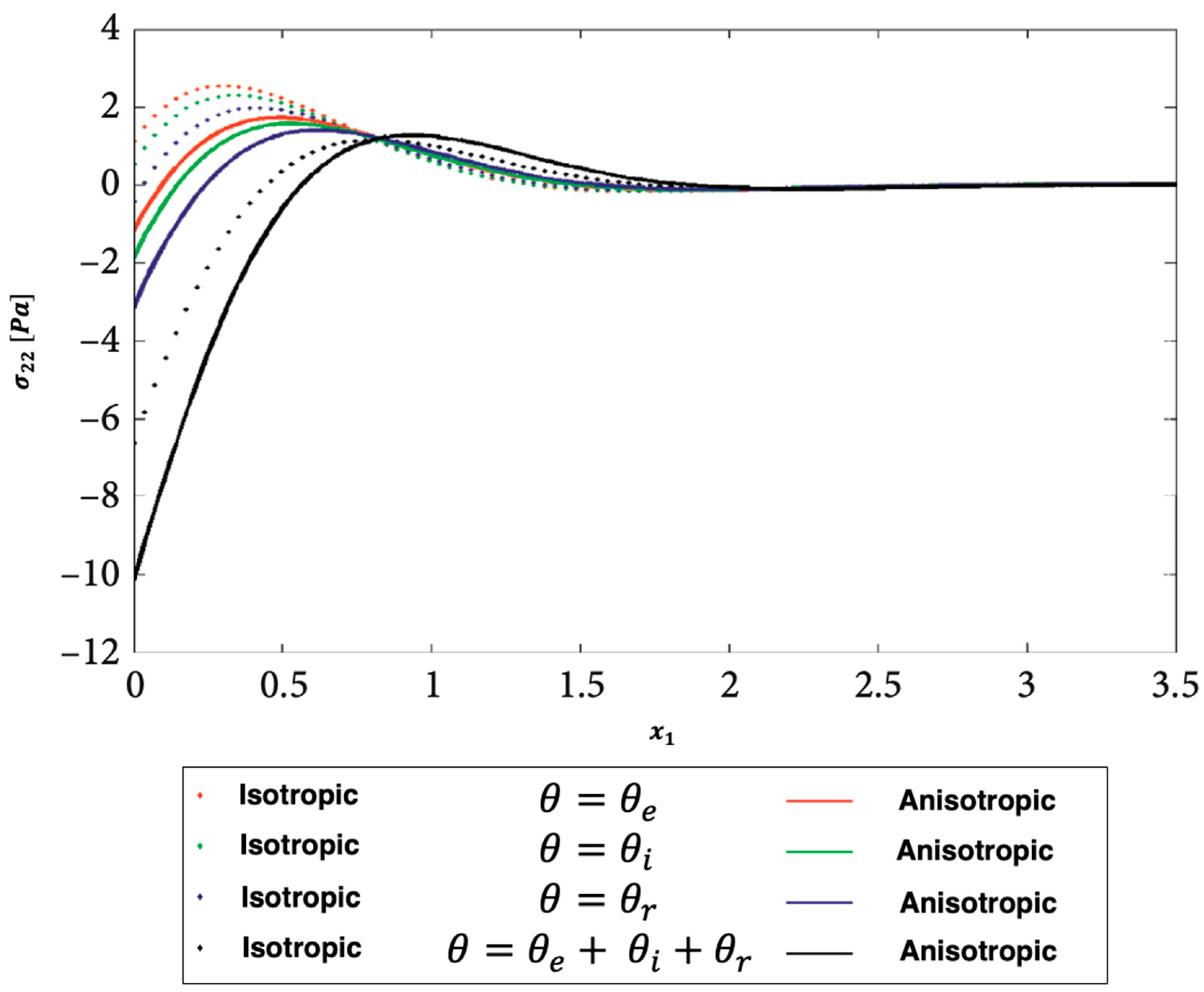
Figure 8 shows the distribution of the nonlinear thermal stress
waves for electron (
), ion (
), phonon (
), and total (
) for isotropic and anisotropic viscoelastic porous structures.
The validity of the outcomes of the suggested technique was not supported by any published works. On the other hand, some literary works can be seen as special cases of the considered general work.
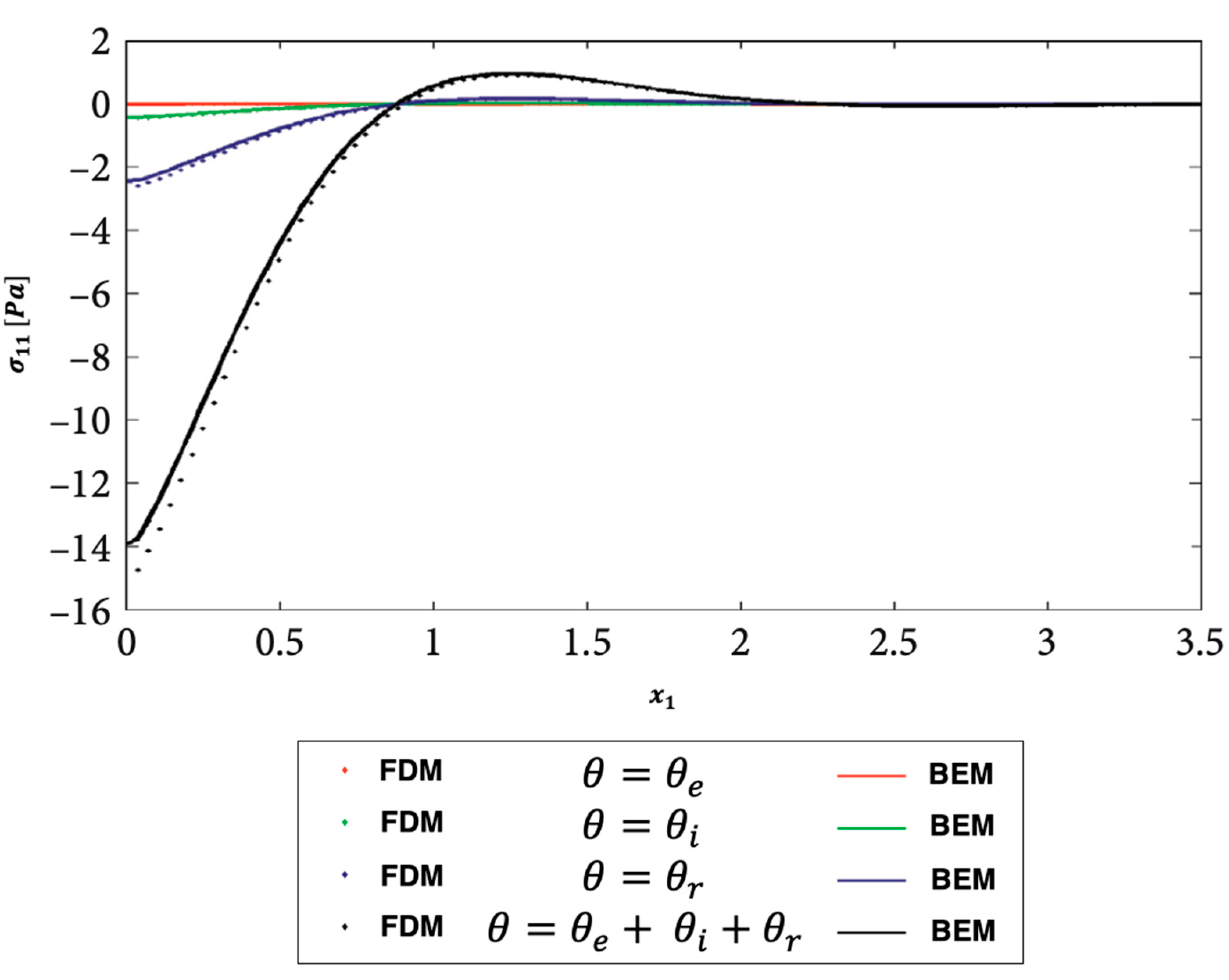
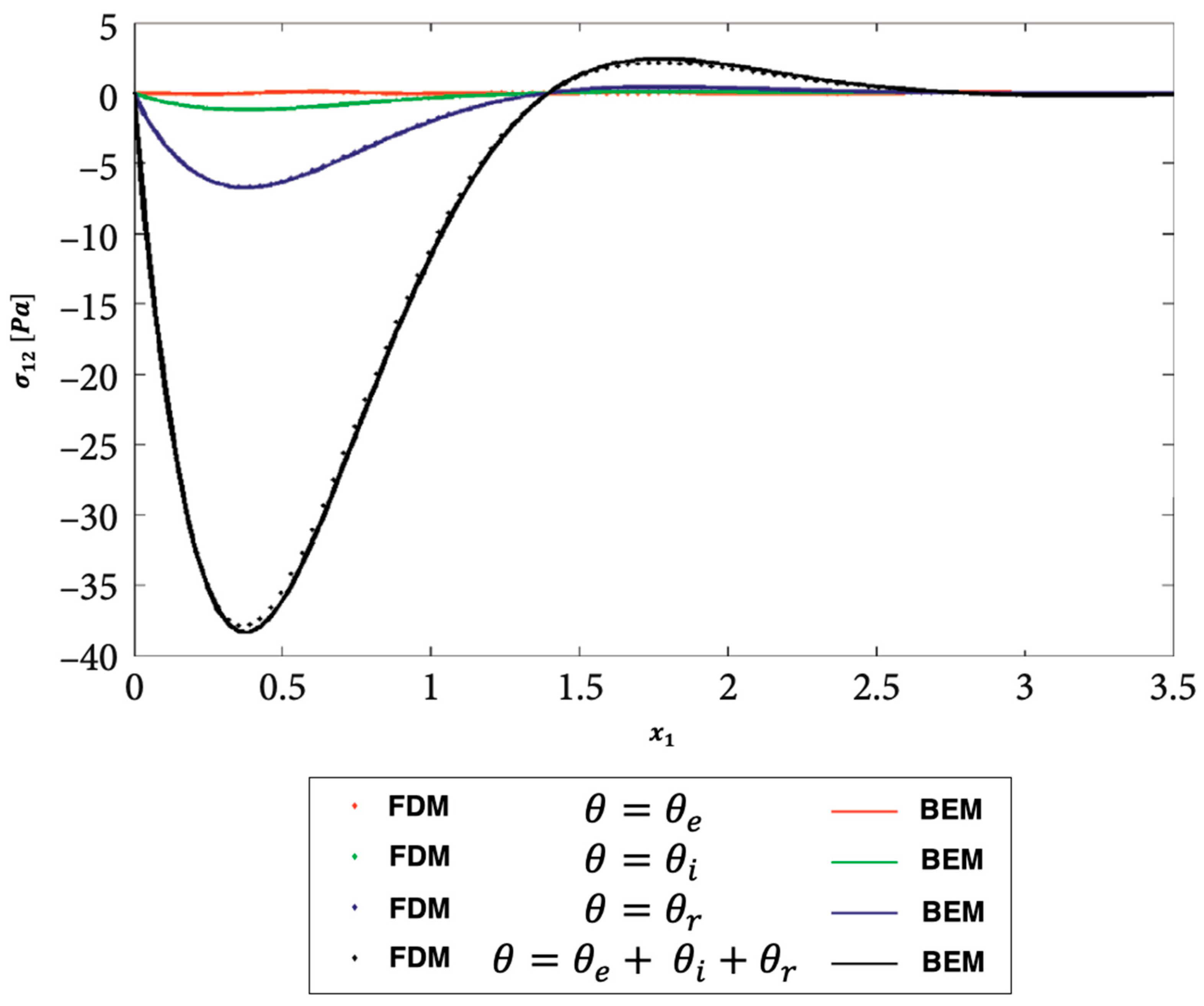
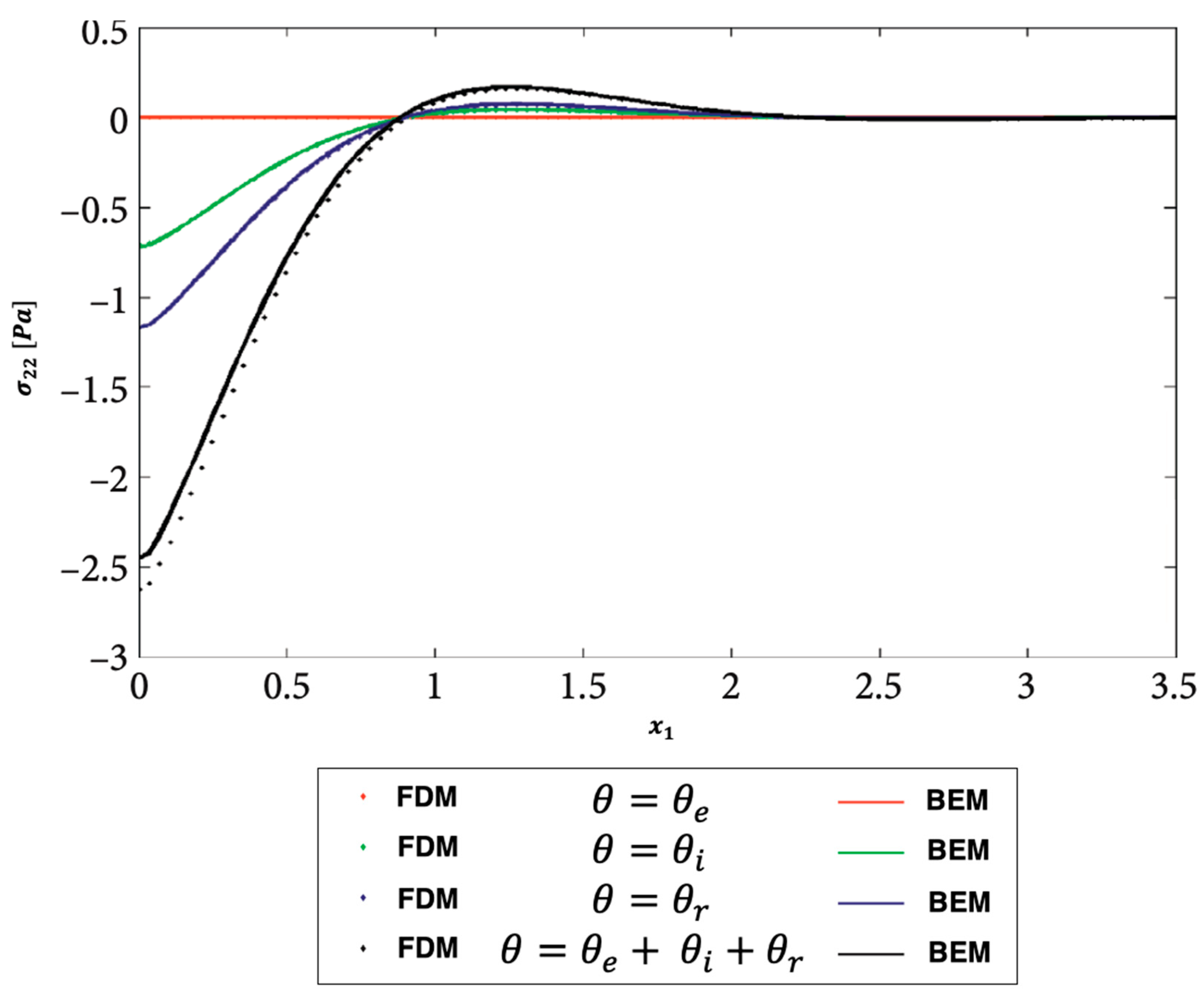
Figure 9,
Figure 10 and
Figure 11 show the distributions of the nonlinear thermal stress
waves along
-axis for electron, ion, phonon and total 3T using the finite difference method (FDM) [
44] and current BEM.
Figure 9 shows the distribution of the nonlinear thermal stress
waves for electron (
), ion (
), phonon (
), and total (
) for FDM and BEM.
Figure 10 shows the distribution of the nonlinear thermal stress
waves for electron (
), ion (
), phonon (
), and total (
) for FDM and BEM.
Figure 11 shows the distribution of the nonlinear thermal stress
waves for electron (
), ion (
), phonon (
), and total (
) for FDM and BEM. These figures clearly show that the BEM and FDM are in excellent agreement, supporting the validity and precision of our proposed BEM approach.
Table 1 shows a comparison of required computer resources for the current BEM results and FDM results of Hu et al. [
44] of modeling of ultrasonic wave propagation problems in three-temperature anisotropic viscoelastic porous media.
6. Conclusion
The main goal of this article is to develop a novel boundary element model for describing ultrasonic thermomechanical interactions in three-temperature anisotropic viscoelastic porous media. Analytical or numerical solutions are always difficult due to the strong nonlinearity of ultrasonic wave propagation in three-temperature porous media problems, necessitating the development of new computational techniques. As a result, we employ a new BEM model to address such problems. The considered BEM model has low RAM and CPU usage due to its advantages such as dealing with more complex shapes of porous media and not requiring the discretization of the internal domain. As a result, the considered BEM is a powerful and adaptable for modeling ultrasonic wave propagation in three-temperature anisotropic viscoelastic porous media. To obtain fundamental solutions, a double integral must be calculated, but this increases the total BEM computation time. To solve the current problem and improve formulation efficiency, we propose a BEM technique. The numerical results are graphed to show the effects of viscosity and anisotropy on nonlinear ultrasonic stress waves in porous media at three temperatures. The proposed methodology's validity, accuracy, and efficiency were demonstrated by comparing the obtained results to the corresponding solution obtained using the finite difference method (FDM). The findings of this paper contribute to the development of mathematical models that can be applied in biology, bioengineering and medicine
Funding
This research was funded by the Deanship of Scientific Research at Umm Al-Qura University, grant number 22UQU4340548DSR16. The APC was funded by the Deanship of Scientific Research at Umm Al-Qura University.
Data Availability Statement
All data generated or analyzed during this study are included in this published article.
Acknowledgments
The author would like to thank the Deanship of Scientific Research at Umm Al-Qura University for supporting this work, grant code 22UQU4340548DSR16.
Conflicts of Interest
The authors declare no conflict of interest.
Nomenclature
|
Convolution with respect to time |
|
Dirichlet datum |
|
Boundary |
|
Neumann datum |
|
Dirichlet boundary |
|
Non-Gaussian temporal profile |
|
Neumann boundary |
|
Total energy intensity |
|
Kronecker delta
|
|
Thermal conductivity tensor |
|
Linear strain tensor |
|
Heat conductive coefficients |
|
Temperature field |
|
poroelastic freedom degrees |
|
Shear moduli |
|
Outward unit normal vector |
|
Viscoelastic constant |
|
Fluid pressure |
|
Fluid volume variation |
|
Singular points |
|
Bulk density |
|
Specific flux of the fluid |
|
Elastic density |
|
Euclidean distance |
|
Fluid density |
|
Heat source intensity |
|
Total stress tensor |
|
Irradiated surface absorptivity |
|
Time |
|
Generalized tractions |
|
Laser pulse time characteristic |
|
Trace of a matrix |
|
Porosity |
|
Regular displacement |
|
Region |
|
Singular displacement |
|
Biot’s coefficient |
|
Displacement |
|
Stress-temperature coefficients |
|
Fluid displacement |
|
Linear elastostatics operator |
|
Poisson’s ratio |
|
Specific heat |
|
Energy exchanging coefficients |
|
Constant elastic moduli |
|
|
|
Young’s moduli |
|
|
|
Body forces |
|
Space coordinates |
|
Shear moduli |
|
Source point |
| |
|
|
Considered point |
References
- Nayak, M.K.; Dash, G.C.; Singhc, L.P. Steady MHD flow and heat transfer of a third grade fluid in wire coating analysis with temperature dependent viscosity. Int. J. Heat Mass Transf. 2014, 79, 1087–1095. [Google Scholar] [CrossRef]
- Nayak, M.K.; Dash, G.C.; Singh, L.P. Unsteady radiative MHD free convective flow and mass transfer of a viscoelastic fluid past an inclined porous plate. Arab. J. Sci. Eng. 2015, 40, 3029–3039. [Google Scholar] [CrossRef]
- Nayak, M.K. Chemical reaction effecton MHD viscoelastic fluid over a stretching sheet through porous medium. Meccanica 2016, 51, 1699–1711. [Google Scholar] [CrossRef]
- Fahmy, M.A. Design Optimization for A Simulation of Rotating Anisotropic Viscoelastic Porous Structures Using Time-Domain OQBEM. Math. Comput. Simul. 2019, 66, 193–205. [Google Scholar] [CrossRef]
- Fahmy, M.A. Modeling and Optimization of Anisotropic Viscoelastic Porous Structures Using CQBEM and Moving Asymptotes Algorithm. Arabian J. Sci. Eng. 2019, 44, 1671–1684. [Google Scholar] [CrossRef]
- Fahmy, M.A.; Shaw, S.; Mondal, S.; Abouelregal, A.E.; Lotfy, K.; Kudinov, I.A.; Soliman, A.H. Boundary Element Modeling for Simulation and Optimization of Three-Temperature Anisotropic Micropolar Magneto-thermoviscoelastic Problems in Porous Smart Structures Using NURBS and Genetic Algorithm. Int. J. Thermophys. 2021, 42, 29. [Google Scholar] [CrossRef]
- Othman, M.I.A.; Fekry, M. Effect of Magnetic Field on Generalized Thermo-viscoelastic Diffusion Medium with Voids. Int. J. Struct. Stab. Dyn. 2016, 16, 1550033. [Google Scholar] [CrossRef]
- Othman, M.I.A.; Fekry, M.; Marin, M. Plane Waves in Generalized Magneto-thermo-viscoelastic Medium with Voids under the Effect of Initial Stress and Laser Pulse Heating. Struct. Eng. Mech. 2020, 73, 621–629. [Google Scholar]
- Othman, M.I.A.; Fekry, M. Effect of Rotation and Gravity on Generalized Thermo-viscoelastic Medium with Voids. Multi. Model. Mater. Struct. 2018, 14, 322–338. [Google Scholar] [CrossRef]
- Othman, M.I.A.; Zidan, M.E.M.; Mohamed, I.E.A. Dual-phase-lag model on thermo-microstretch elastic solid under the effect of initial stress and temperature-dependent. Steel Compos. Struct. 2021, 38, 355–363. [Google Scholar]
- Xu, Z.D.; Ge, T.; Liu, J. Experimental and theoretical study of high energy dissipation viscoelastic dampers based on acrylate rubber matrix. ASCE J. Eng. Mech. 2020, 146, 04020057. [Google Scholar] [CrossRef]
- Pei, R.Z.; Jing, L.; Cheng, W.C.; Xue, J.P. Boundary element method (BEM) for solving normal or inverse bio-heat transfer problem of biological bodies with complex shape. J. Therm. Sci. 1995, 4, 117–124. [Google Scholar]
- Ooi, E.H.; Ang, W.T.; Ng, E.Y.K. A boundary element model for investigating the effects of eye tumor on the temperature distribution inside the human eye. Comput. Biol. Med. 2009, 39, 667–677. [Google Scholar] [CrossRef] [PubMed]
- Zhou, J.; Chen, J.K.; Zhang, Y. Simulation of Laser-Induced Thermotherapy Using a Dual-Reciprocity Boundary Element Model with Dynamic Tissue Properties. IEEE Trans. Biomed. Eng. 2010, 57, 238–245. [Google Scholar] [CrossRef] [PubMed]
- Ng, E.Y.K.; Tan, H.M.; Ooi, E.H. Boundary element method with bioheat equation for skin burn injury. Burns 2009, 35, 987–997. [Google Scholar] [CrossRef]
- Majchrzak, E.; Turchan, L. The general boundary element method for 3D dual-phase lag model of bioheat transfer. Eng. Anal. Bound. Elem. 2015, 50, 76–82. [Google Scholar] [CrossRef]
- Bottauscio, O.; Chiampi, M.; Zilberti, L. Boundary Element Solution of Electromagnetic and Bioheat Equations for the Simulation of SAR and Temperature Increase in Biological Tissues. IEEE Trans. Magn. 2012, 48, 691–694. [Google Scholar] [CrossRef]
- Deng, Z.S.; Liu, J. Modeling of multidimensional freezing problem during cryosurgery by the dual reciprocity boundary element method. Eng. Anal. Bound. Elem. 2004, 28, 97–108. [Google Scholar] [CrossRef]
- Partridge, P.W.; Wrobel, L.C. A coupled dual reciprocity BEM/genetic algorithm for identification of blood perfusion parameters. Int. J. Numer. Methods Heat Fluid Flow 2009, 19, 25–38. [Google Scholar] [CrossRef]
- Chan, C.L. Boundary Element Method Analysis for the Bioheat Transfer Equation. J. Biomech. Eng. 1992, 114, 358–365. [Google Scholar] [CrossRef]
- Wrobel, L.C. The Boundary Element Method, Applications in Thermos-Fluids and Acoustics; Wiley: New York, NY, USA, 2002; Volume 1. [Google Scholar]
- Lua, W.Q.; Liub, J.; Zenga, Y. Simulation of the thermal wave propagation in biological tissues by the dual reciprocity boundary element method. Eng. Anal. Bound. Elem. 1998, 22, 167–174. [Google Scholar] [CrossRef]
- Fahmy, M.A. A time-stepping DRBEM for magneto-thermo-viscoelastic interactions in a rotating nonhomogeneous anisotropic solid. Int. J. Appl. Mech. 2011, 3, 711–734. [Google Scholar] [CrossRef]
- Fahmy, M.A. A time-stepping DRBEM for the transient magneto-thermo-visco-elastic stresses in a rotating non-homogeneous anisotropic solid. Eng. Anal. Bound. Elem. 2012, 36, 335–345. [Google Scholar] [CrossRef]
- Fahmy, M.A. Transient magneto-thermoviscoelastic plane waves in a non-homogeneous anisotropic thick strip subjected to a moving heat source. Appl. Math. Modell. 2012, 36, 4565–4578. [Google Scholar] [CrossRef]
- Fahmy, M.A. The effect of rotation and inhomogeneity on the transient magneto-thermoviscoelastic stresses in an anisotropic solid. ASME J. Appl. Mech. 2012, 79, 051015. [Google Scholar] [CrossRef]
- Fahmy, M.A. Implicit-Explicit time integration DRBEM for generalized magneto-thermoelasticity problems of rotating anisotropic viscoelastic functionally graded solids. Eng. Anal. Bound. Elem. 2013, 37, 107–115. [Google Scholar] [CrossRef]
- Fahmy, M.A. Generalized magneto-thermo-viscoelastic problems of rotating functionally graded anisotropic plates by the dual reciprocity boundary element method. J. Therm. Stress. 2013, 36, 1–20. [Google Scholar] [CrossRef]
- Fahmy, M.A. Shape design sensitivity and optimization for two-temperature generalized magneto-thermoelastic problems using time-domain DRBEM. J. Therm. Stress. 2018, 41, 119–138. [Google Scholar] [CrossRef]
- Fahmy, M.A. Shape design sensitivity and optimization of anisotropic functionally graded smart structures using bicubic B-splines DRBEM. Eng. Anal. Bound. Elem. 2018, 87, 27–35. [Google Scholar] [CrossRef]
- Fahmy, M.A. Boundary Element Algorithm for Modeling and Simulation of Dual Phase Lag Bioheat Transfer and Biomechanics of Anisotropic Soft Tissues. Int. J. Appl. Mech. 2018, 10, 1850108. [Google Scholar] [CrossRef]
- Hosseini, M.; Paparisabet, M.A. The Effects of Blood Flow on Blood Vessel Buckling Embedded in Surrounding Soft Tissues. Int. J. Appl. Mech. 2016, 8, 1650065. [Google Scholar] [CrossRef]
- Azzez, K.; Chaabane, M.; Abellan, M.A.; Bergheau, J.M.; Zahouani, H.; Dogui, A. Relevance of Indentation Test to Characterize Soft Biological Tissue: Application to Human Skin. Int. J. Appl. Mech. 2018, 10, 1850074. [Google Scholar] [CrossRef]
- Biot, M.A. Theory of propagation of elastic waves in a fluid- saturated porous solid. II. Higher frequency range. J. Acoust. Soc. Am. 1956, 28, 179–191. [Google Scholar] [CrossRef]
- Schanz, M. Wave Propagation in Viscoelastic and Poroelastic Continua; Lecture Notes in Applied Mechanics; Springer: New York, NY, USA, 2001; Volume 2. [Google Scholar]
- Bonnet, G. Basic singular solutions for a poroelastic medium in the dynamic range. J. Acoust. Soc. Am. 1987, 82, 1758–1763. [Google Scholar] [CrossRef]
- Messner, M.; Schanz, M. A regularized collocation boundary element method for linear poroelasticity. Comput. Mech. 2011, 47, 669–680. [Google Scholar] [CrossRef]
- Ding, C. A Symmetric Successive Overrelaxation (SSOR) based Gauss- Seidel Massive MIMO Detection Algorithm. J. Phys. Conf. Ser. 2020, 1438, 012005. [Google Scholar] [CrossRef]
- Steinbach, O. Numerical Approximation Methods for Elliptic Boundary Value Problems; Springer: New York, NY, USA, 2008. [Google Scholar]
- Kielhorn, L. A time-domain symmetric Galerkin BEM for viscoelastodynamics. In Computation in Engineering and Science; Brenn, G., Holzapfel, G.A., Schanz, M., Steinbach, O., Eds.; Graz University of Technology, Institute of Applied Mechanics: Austria, 2009. [Google Scholar]
- Lubich, C. Convolution quadrature and discretized operational calculus. I. Numer. Math. 1988, 52, 129–145. [Google Scholar] [CrossRef]
- Lubich, C. Convolution quadrature and discretized operational calculus II. Numer. Math. 1988, 52, 413–425. [Google Scholar] [CrossRef]
- Morrow, D.A.; Haut Donahue, T.L.; Odegard, G.M.; Kaufman, K.R. Transversely isotropic tensile material properties of skeletal muscle tissue. J. Mech. Behav. Biomed. Mater. 2010, 3, 124–129. [Google Scholar] [CrossRef] [PubMed]
- Hu, N.; Wang, M.; Qiu, B.; Tao, Y. Numerical Simulation of Elastic Wave Field in Viscoelastic Two-Phasic Porous Materials Based on Constant Q Fractional-Order BISQ Model. Materials 2022, 15, 1020. [Google Scholar] [CrossRef] [PubMed]
Figure 1.
Computational domain of the current problem.
Figure 1.
Computational domain of the current problem.
Figure 2.
BEM model of the current problem.
Figure 2.
BEM model of the current problem.
Figure 3.
Propagation of the nonlinear thermal stress waves along -axis for electron, ion, phonon and total 3T with and without viscosity effect.
Figure 3.
Propagation of the nonlinear thermal stress waves along -axis for electron, ion, phonon and total 3T with and without viscosity effect.
Figure 4.
Propagation of the nonlinear thermal stress waves along -axis for electron, ion, phonon and total 3T with and without viscosity effect.
Figure 4.
Propagation of the nonlinear thermal stress waves along -axis for electron, ion, phonon and total 3T with and without viscosity effect.
Figure 5.
Propagation of the nonlinear thermal stress waves along -axis for electron, ion, phonon and total 3T with and without viscosity effect.
Figure 5.
Propagation of the nonlinear thermal stress waves along -axis for electron, ion, phonon and total 3T with and without viscosity effect.
Figure 6.
Propagation of the nonlinear thermal stress waves along -axis for electron, ion, phonon and total 3T for isotropic and anisotropic viscoelastic porous structures.
Figure 6.
Propagation of the nonlinear thermal stress waves along -axis for electron, ion, phonon and total 3T for isotropic and anisotropic viscoelastic porous structures.
Figure 7.
Propagation of the nonlinear thermal stress waves along -axis for electron, ion, phonon and total 3T for isotropic and anisotropic viscoelastic porous structures.
Figure 7.
Propagation of the nonlinear thermal stress waves along -axis for electron, ion, phonon and total 3T for isotropic and anisotropic viscoelastic porous structures.
Figure 8.
Propagation of the nonlinear thermal stress waves along -axis for electron, ion, phonon and total 3T for isotropic and anisotropic viscoelastic porous structures.
Figure 8.
Propagation of the nonlinear thermal stress waves along -axis for electron, ion, phonon and total 3T for isotropic and anisotropic viscoelastic porous structures.
Figure 9.
Propagation of the nonlinear thermal stress waves along -axis for electron, ion, phonon and total 3T for FDM and BEM.
Figure 9.
Propagation of the nonlinear thermal stress waves along -axis for electron, ion, phonon and total 3T for FDM and BEM.
Figure 10.
Propagation of the nonlinear thermal stress waves along -axis for electron, ion, phonon and total 3T for FDM and BEM.
Figure 10.
Propagation of the nonlinear thermal stress waves along -axis for electron, ion, phonon and total 3T for FDM and BEM.
Figure 11.
Propagation of the nonlinear thermal stress waves along -axis for electron, ion, phonon and total 3T for FDM and BEM.
Figure 11.
Propagation of the nonlinear thermal stress waves along -axis for electron, ion, phonon and total 3T for FDM and BEM.
Table 1.
A comparison of the required computer resources for modeling of ultrasonic wave propagation problems in three-temperature anisotropic viscoelastic porous media.
Table 1.
A comparison of the required computer resources for modeling of ultrasonic wave propagation problems in three-temperature anisotropic viscoelastic porous media.
| |
BEM |
FDM |
| Number of nodes |
66 |
40000 |
| Number of elements |
36 |
16000 |
| CPU time (min) |
2 |
160 |
| Memory (MByte) |
1 |
140 |
| Disc space (MByte) |
0 |
200 |
| Accuracy of results (%) |
1 |
2.0 |
|
Disclaimer/Publisher’s Note: The statements, opinions and data contained in all publications are solely those of the individual author(s) and contributor(s) and not of MDPI and/or the editor(s). MDPI and/or the editor(s) disclaim responsibility for any injury to people or property resulting from any ideas, methods, instructions or products referred to in the content. |
© 2023 by the authors. Licensee MDPI, Basel, Switzerland. This article is an open access article distributed under the terms and conditions of the Creative Commons Attribution (CC BY) license (http://creativecommons.org/licenses/by/4.0/).
