3.1. Austenite Nucleation
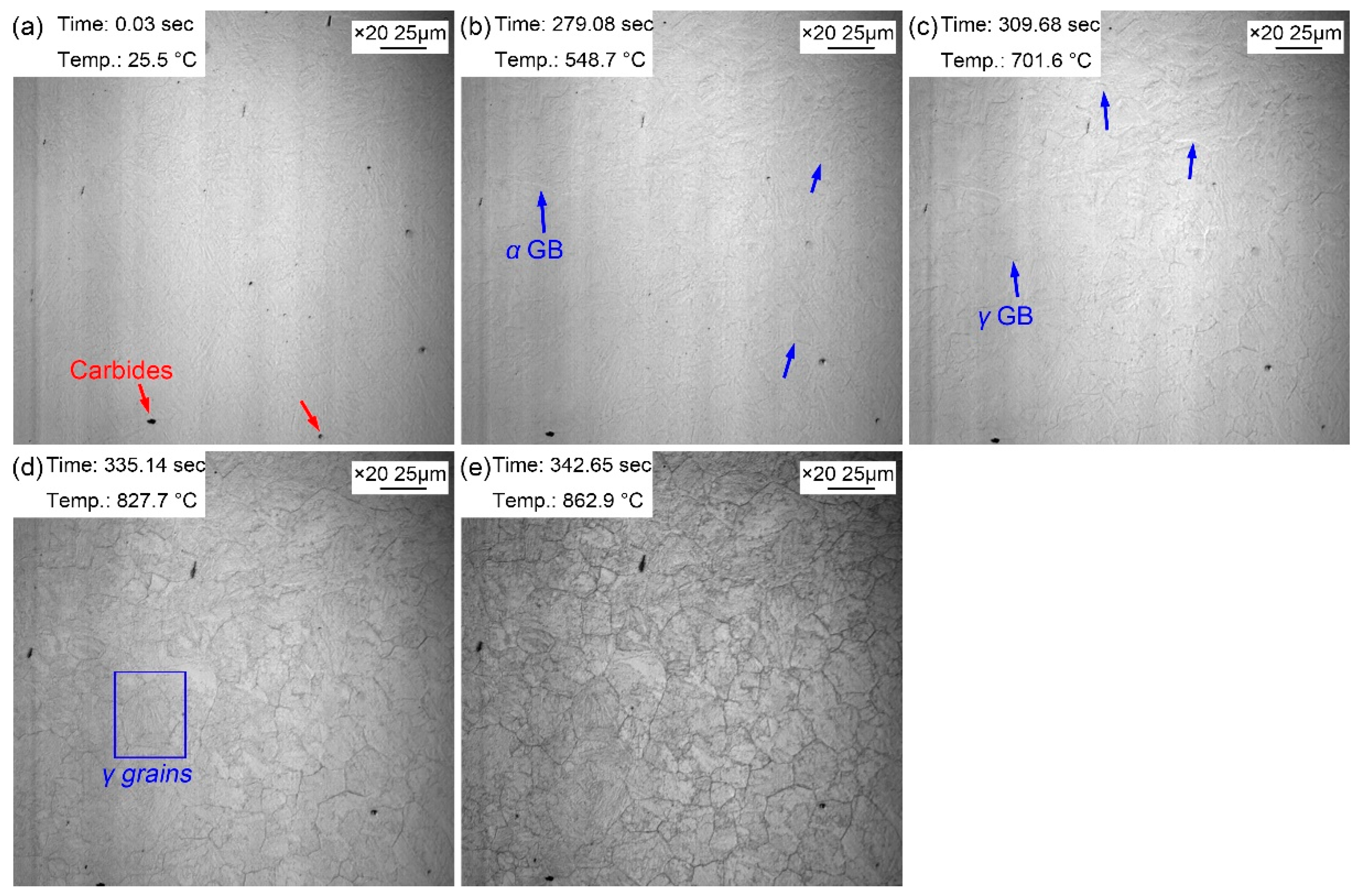
Figure 2 manifests the morphologic changes of the sample from room temperature to preset temperature of 860 ℃. Some dark particles existed on the surface of the sample, and these dark particles were likely to be the second phase precipitates with a larger size (
Figure 2a). When the temperature increased to 548.7 ℃, some corrugated folds began to appear on the surface of the bright sample. These folds were the grain boundaries of the initial ferrite (pearlite) of the sample, which gradually emerged under the condition of thermal etching (
Figure 2b). As the temperature increased to 701.6 ℃, another corrugated fold gradually covered the grain boundaries of the existing ferrite (
Figure 2c). And this corrugated fold became more and more clear and gradually formed the grain boundaries of polygonal grains as the temperature continued to rise to 827.7 ℃ (
Figure 2d) and 862.9 ℃ (
Figure 2e). It was inferred that the corrugated fold at 701.6 ℃ was austenitic grain boundary, that is, the Ac1 temperature (the beginning temperature at which the pearlite transforms to austenite during heating process) was about 701.6 ℃ when the steel was reheated at 5 ℃/s. The measured Ac1 temperature of this experimental steel was about 658 ℃ using thermal simulated test, but the Ac1 temperature obtained via in-situ observation was apparently higher. This was because the measured Ac1 temperature was obtained with a very slow heating rate (about 0.1 ℃/s), and the measured Ac1 temperature increased with the increase of the heating rate (5 ℃/s). Moreover, sample fleetly finished the austenization process with a faster heating rate. When the temperature was 862.9 ℃ (
Figure 2e), the austenization process completed, but the grain boundary morphology of the initial microstructure remained. At this time, the visible black precipitates became clearer and their size increased.
Austenite transformation is related to nucleation rate and growth rate, which can be expressed as Equations (1) and (2) [
30,
31]:
Where, N is the nucleation rate, G is the growth rate,
and
are the nucleation and growth activation energies,
and
are the impact factors between structure and nucleation with growth, and
is the superheat. It reveals that the superheat increased with the increase of the heating rate, which increased the nucleation rate and growth rate of austenitic transformation. Therefore, the rate of austenitic transformation increased significantly, and the time required from the initial to complete austenitizing was greatly reduced, and then the required phase transition interval was correspondingly reduced. In addition, the transformation of steel during continuous heating can be equivalent to the accumulation of countless isothermal transformations. The relationship between isothermal incubation period and transition temperature can be established using Scheil superposition principle [
32].
Differential Equation (4) was obtained when
∆t was small enough.
Where,
∆t and
dt are the transformation time at temperature
T,
Ai and
A(T) are the corresponding incubation period. The relationship between incubation period and transition temperature in the inverse eutectic transition is shown in Equation (5):
Relationships between transformation rate
C, transformation beginning and ending temperatures
Ts and
Tf, and heating rate
v are interpreted by Equations (6) and (7) when transformation volume is
f.
Where, T1 is equilibrium temperature, tn is the time to the transformation ending temperatures Tf. It proves that with the increase of the heating rate, both the initial temperature and the end temperature of the phase transition increased. In addition, the dissolution and diffusion of carbonitrides was inevitable during the austenitizing process of experimental steel, and atoms migrated between phases through the diffusion mechanism. With the increase of heating rate, the diffusion of carbon and alloying elements at equilibrium temperature decreased, thus increasing the austenitic transition temperature. In the process of continuous heating, with the increase of temperature, the diffusion coefficient of atoms increased greatly, and the diffusion rate of atoms accelerated significantly, so that the driving force of austenite phase transformation was obviously enhanced.
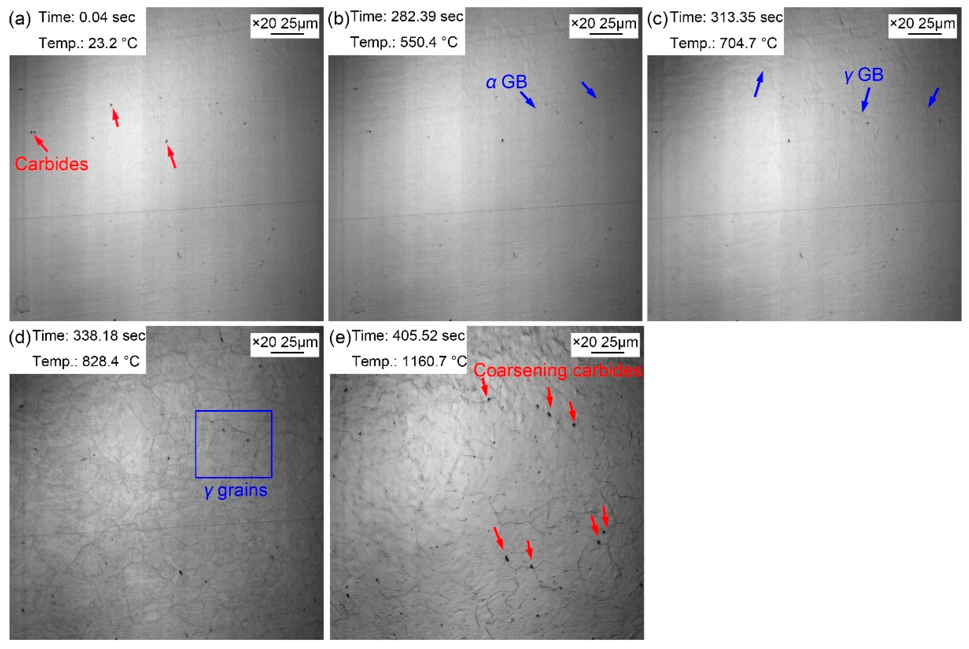
The morphologic variation of the sample from room temperature to preset temperature of 1160
℃ is displayed in Figure 3. Some dark particles basically determined to be the second phase precipitates appeared on the surface of the sample (
Figure 3a). Some corrugated folds began to appear on the surface of the bright sample when the temperature
increased to 550.4 ℃ (
Figure 3b). As the temperature
increased to 704.7 ℃ (
Figure 3c), another corrugated fold gradually covered the grain boundaries of the existing ferrite structure. The corrugated fold became more and more clear and gradually formed the grain boundaries of polygonal grains when the temperature was 828.4℃ (
Figure 3d). It was inferred that the corrugated fold at 704.7 ℃ was austenitic grain boundaries as well. The temperature for the grain boundary appeared was basically the same as that in specimen reheated to 860 ℃. This was because the heating process of the two samples were the same before heating to 860 ℃. However, when the sample was reheated to 1160 ℃ (
Figure 3e), more large size grains appeared accompanied with the disappeared small size grains and the grain boundaries became sharper and clearer. In addition, clearly visible second phase precipitated particles increased significantly, and its size has gradually coarsened. It can be explained by the gradual dissolution of some invisible fine dispersed second phase particles when heating from 828.4 ℃ to 1160 ℃, which increasing of austenite grain boundary mobility and then resulting in the partitioning of small grains and the coarsening of austenite grains quickly. It is clear that the increase amount of the second phase precipitated particles was attributed to the insufficient thermal stability in some second phase precipitated particles at high temperature. Compared with the sample quenched at 860 ℃, the austenite grains of the sample quenched at 1160 ℃ coarsened obviously.
3.2. Austenite Growing
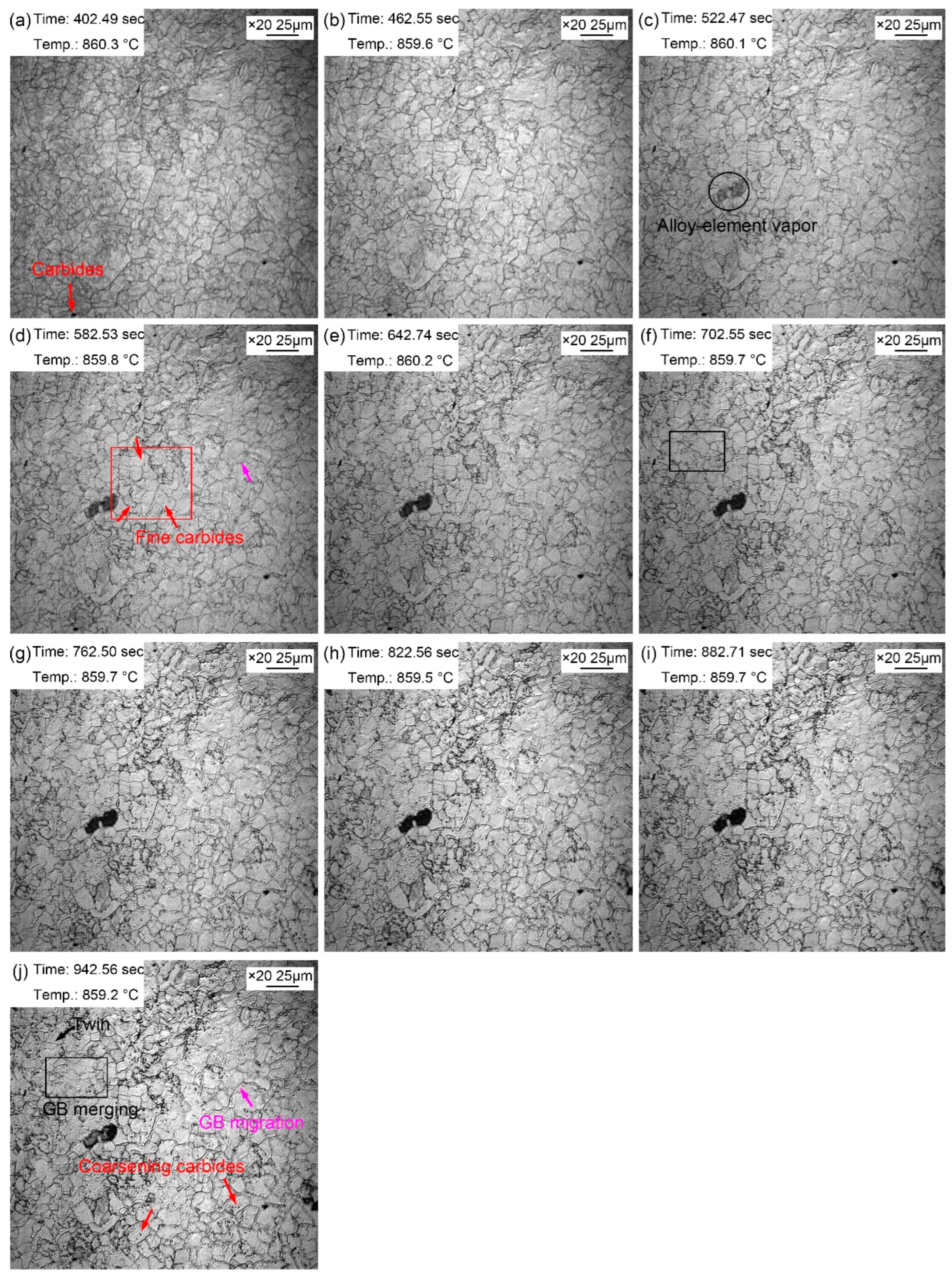
Figure 4 shows the morphologic changes of the sample from 1~10 minutes with a time interval of 1 min when the quenching temperature was 860 ℃. Compared with the morphology just reheated to the preset temperature, the grain boundaries of austenite grains were clearer after being held at 860 ℃ for 1 min (
Figure 4a). This is because grain boundary grooves would be more easily exposed under the condition of longer thermal etching. In addition, the austenite grain boundaries were narrow and straight with a grain boundaries angle of 120°. Some local small grains gradually merged into large ones during the holding, as shown in the rectangular (
Figure 4f,j). In addition, austenite grain boundaries also expanded and migrated to form large grains during the holding, as shown by pink arrows (
Figure 4d,j). The gradual merging of small grains and migration of some grain boundaries indicated that grain growth occurred gradually during the process of thermal holding, but the growth process and trend were not obvious.
During the thermal holding process, the dark fog-like substance shown by the oval in
Figure 4c appeared. The dark fog-like substance gradually turned black, and then disappeared in the subsequent holding process. This dark mist was the vapor of alloying elements, and some of which tend to steam outward from the steel matrix when reheated. In addition to the clearly visible precipitates at the reheating beginning, many fine dispersed particles also appeared in the austenite grains during the thermal holding, as shown in
Figure 4d. These fine second phase particles gradually appeared because part of the nano-second phase particles matured and gradually emerged, and some of the unprecipitated second phase particles gradually precipitated from the matrix. The second phase particles matured during the thermal holding, as shown in
Figure 4j.
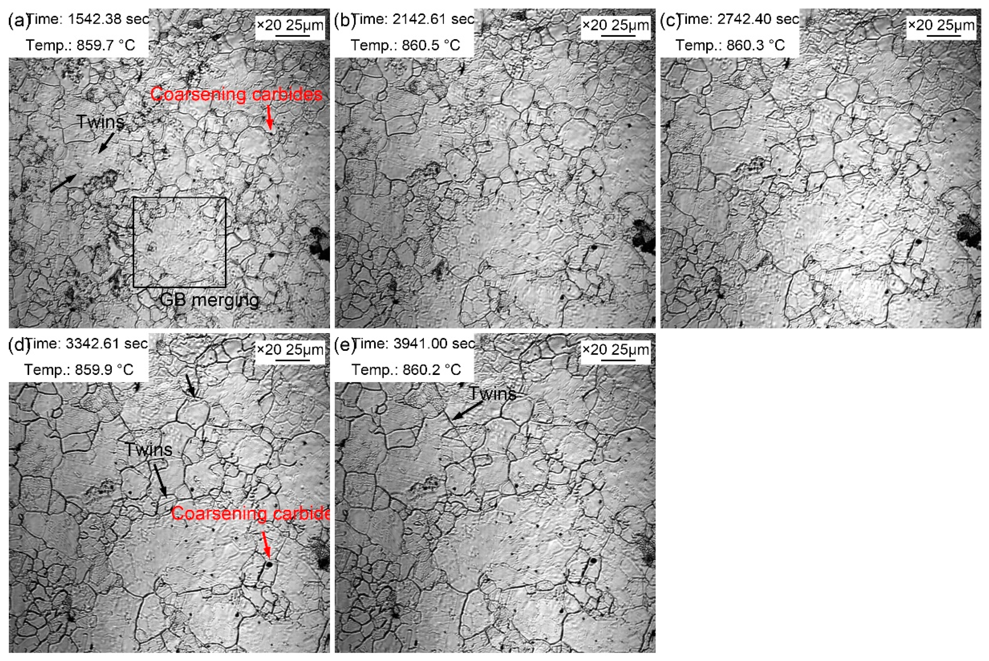
The morphologic variation with a time interval of 10 min from 20~60 minutes at the quenching temperature of 860 ℃ is exhibited in
Figure 5. Compared with morphology in the holding time of 10 min, the coarsening of the second phase particles was more obvious, and there were more areas where small grains merged into large grains. In addition, twin crystals could be observed in austenite grains (
Figure 5a). The existing dark fog-like steam gradually volatilized and disappeared during the thermal holding, while at the same time, the dark fog-like steam appeared in other areas. It may be explained by the uneven distribution of some alloying elements. Besides, the austenite grain coarsening was obvious during the thermal holding, in which the proportion of small grains decreased gradually, and the volume fraction of large grains increased significantly. Moreover, and the intramural twins were more clearly visible (
Figure 5e). The intracrystalline twins in this sample can be considered as annealing twins. There were more alloying elements in the steel, which significantly reduced the stacking fault energy. Compared with ordinary carbon steel, intracrystalline twins were more likely to occur in alloyed steels. The appearance of twins segregated and refined the grains, thus increasing the resistance of dislocation movement, and then strengthening the steel.
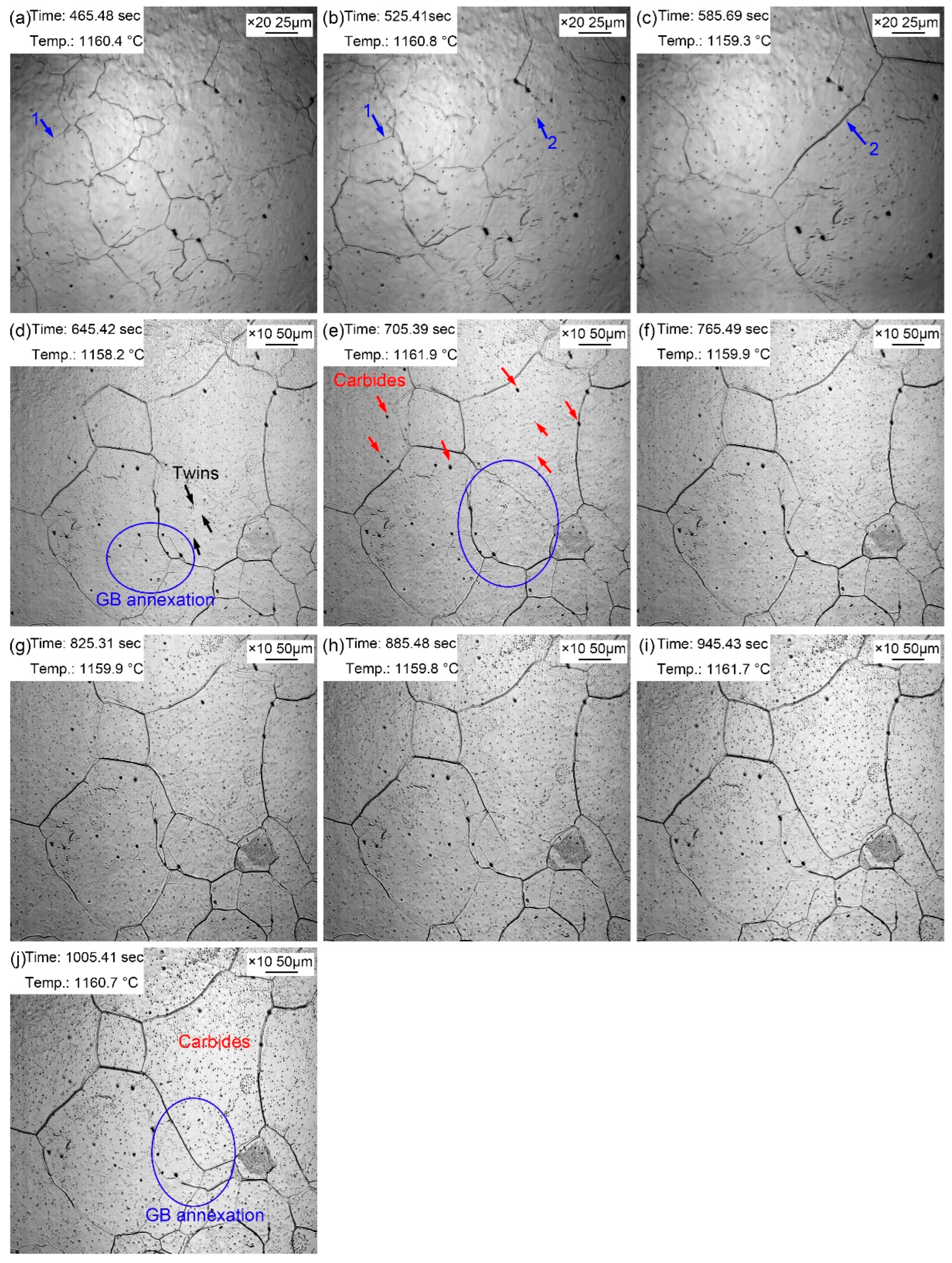
Figure 6 presents the morphologic evolution of the sample from 1~10 minutes at the quenching temperature of 1160 ℃ with a time interval of 1 minute. Compared with the sample just reheated to the preset temperature, the grain boundaries of austenite grains were much clearer after holding at 1160 ℃ for 1 min (
Figure 6a) by the continuous thermal etching. The migration of grain boundaries was obvious with the extension of holding time, as shown in
Figure 6a→6b (blue arrow 1) and 8b→8c (blue arrow 2). Part of the original grain boundaries gradually faded away during the process of grain boundary migration, and the old ones were gradually filled in, leaving only a few traces. In addition, except the outward expansion of grain boundaries, there was an obvious phenomenon that small grains were partitioned by surrounding large grains, as shown in the oval in
Figure 6d. The alloy element steam as shown in
Figure 5c also appeared during the thermal holding process in specimen reheated to 1160 ℃. The alloy element steam gradually turned black, and then disappeared in the subsequent holding process. Besides, many annealing twins traversing the whole grain or occupying the whole grains were captured in the austenite grains. The second phase particles ripened during the holding process, as shown in
Figure 6j. The gradual appearance of fine second phase particles during the thermal holding was attributed to the ripening of nanoparticles at 1160 ℃, which was captured by limited magnification. Comparing with the grain morphology at 860 ℃ for 20~60 minutes, the grain size was obviously coarsened when the quenching temperature was 1160 ℃, and the number of small grains was very small. The coarsen second phase particles increased obviously at 1160 ℃, and there were many dense fine second phase particles inside the grain. The microalloying elements in steel were mainly Ti and V. Some small particles precipitated and gradually dissolved into the matrix at 1160 ℃, while some dispersion particles with excellent thermal stability ripened and exposed by thermal etching. Firstly, according to the formula of solid solubility product, some carbonitride particles redissolved in the matrix due to the increase in temperature. In addition, since the solute concentration around small particles was greater than that around large particles, the solute atoms spread from small particles to large particles, resulting in the redissolution of small particles and growing in larger particles. Therefore, the fine precipitates gradually redissolved, and continuously formed large size carbonitride particles when the holding time was long enough at 1160 ℃.
The coarsening of austenite grains at 1160 ℃ was related to the redissolution of the second phase particles. Firstly, the atomic size of V/Ti was very different with Fe, which has a certain solute atomic dragging effect. Reconcentration of a large number of solute atoms such as vanadium (V) and titanium (Ti) at grain boundaries or subgrain boundaries could prevented the migration of grain boundaries and thus inhibited recrystallization. In addition, the second phase particles preferentially precipitated at grain boundaries and dislocation lines, pinning the austenite grain boundaries and hindering the growth of austenite grains. The grain boundary migration was the essence of austenite grain growth. The surface energy increased when grain boundaries contacted with the second phase precipitated particle. Only when the thermal activation energy was greater than the increment of surface energy, the second phase particles will be cut or bypassed by the grain boundary. Therefore, the second phase particles significantly slowed down the formation rate of austenite and prevented the growth of grains.
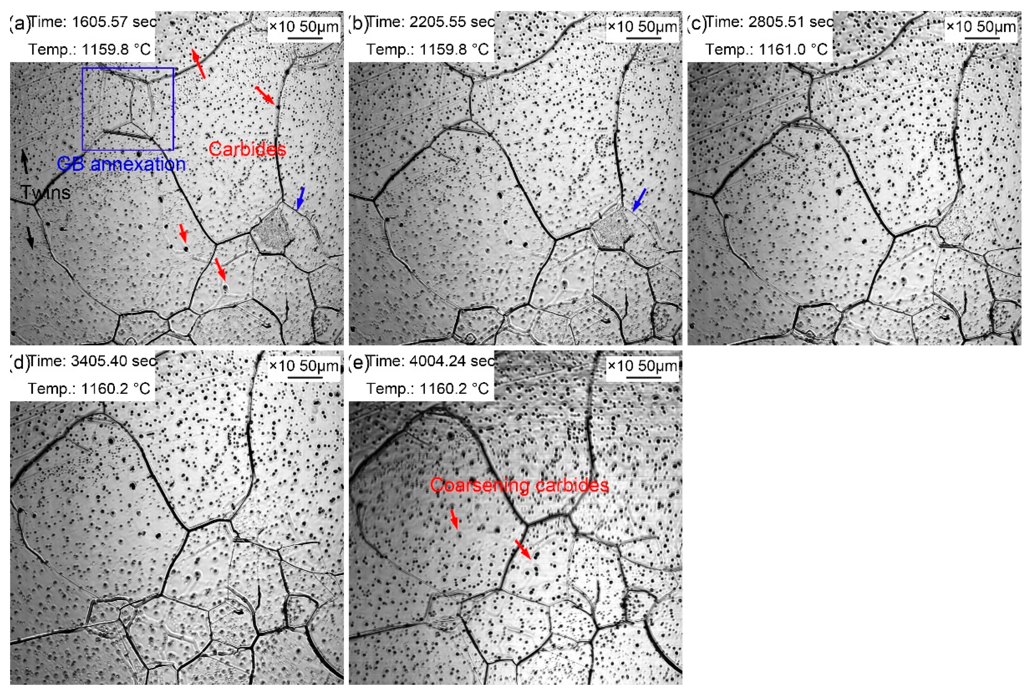
Figure 7 displays the morphologic changes with a time interval of 10 min from 20 to 60 minutes at the quenching temperature of 1160 ℃. Dense small black particles formed in the austenite grains. It signified that the coarsening of the second phase particles was more obvious compared with those during the holding time of 10 minutes. In addition, the grain boundaries of small-size austenite were gradually absorbed by the surrounding large-size austenite. Besides, apparent twins were observed in austenite grains (
Figure 7a). The dark fog-like steam gradually volatilized and disappeared with the extension of holding time. Furthermore, austenite grain coarsening still occurred during the holding at 20~60 min, in which the proportion of small grains furtherly decreased, and the volume fraction of large grains significantly increased. The intra twins were more clearly visible (
Figure 7e) because of the larger austenite grains.
3.3. Grain Size
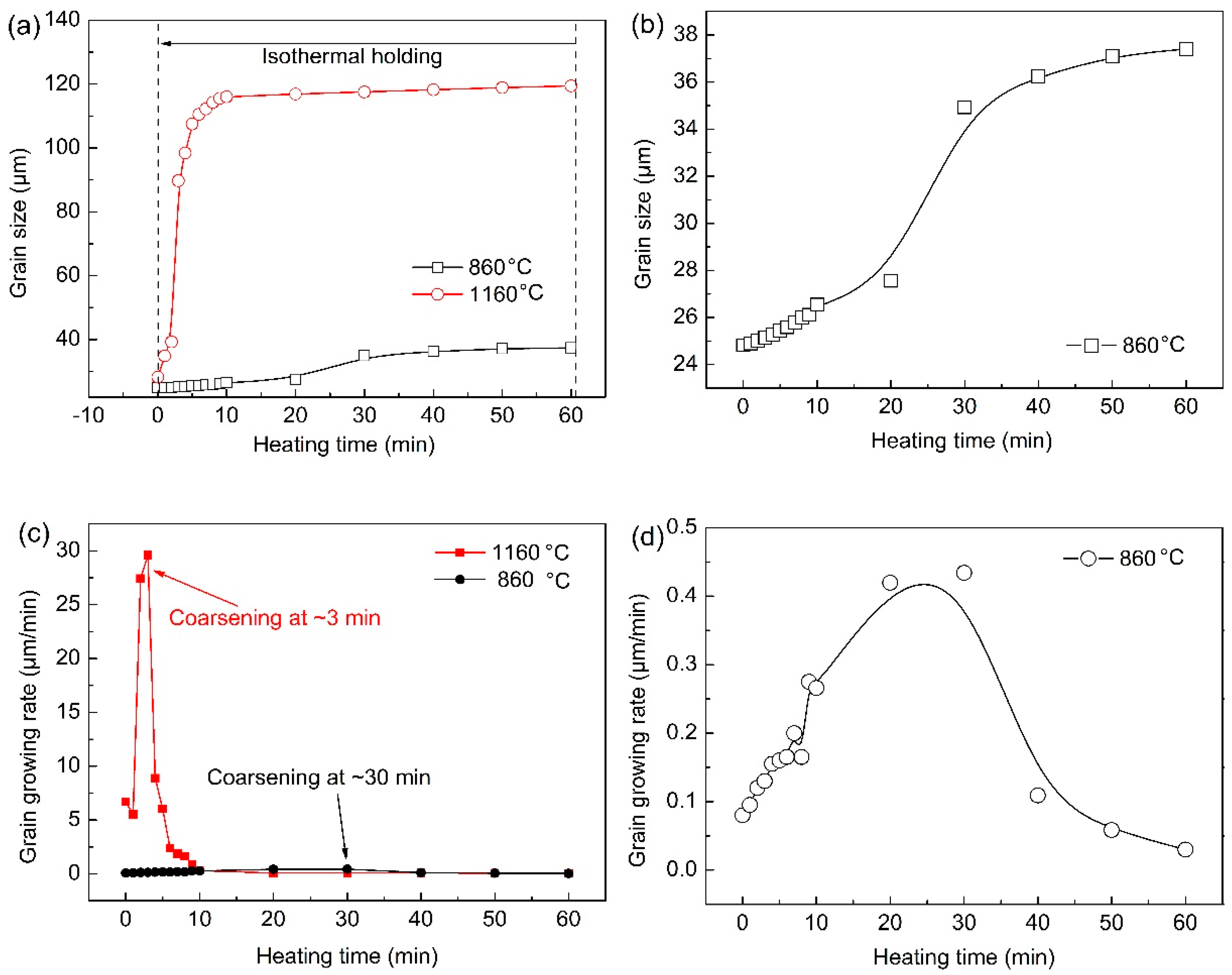
Figure 8 summaries the grain size and growth rate of austenite from the formation of austenite to the thermal holding under different quenching temperatures. Enough grains should be ensured to improve the statistical accuracy in the statistical process. Grains less than half a grain were not counted, and grains larger than half were considered as a grain. There was little difference in austenite grain size under two different quenching temperatures during the reheating stage before preset quenching temperatures. However, the austenite grain size in specimen reheated to 860 ℃ was always smaller than those in the sample with a quenching temperature of 1160 ℃.
Figure 8b shows the growth law of austenite grains with time when the quenching temperature was 860 ℃. The growth process was relatively slow, and the obvious coarsening of austenite grains was completed after holding for about 30 min. The growth process of austenite grains was very rapid and intense, and the coarsening of austenite grains has been completed within 10 minutes at the quenching temperature of 1160 ℃. Austenite grain growth rate curves at different quenching temperatures were obtained through the first derivative of austenite grain size and holding time (
Figure 8b,d). The austenite grain growth rate was significantly faster when the quenching temperature was 1160 ℃ than that at 860 ℃. In addition, when the quenching temperature was 1160 ℃, the maximum austenitic growth rate appeared at the holding time of ~3 min, whereas the maximum austenitic growth rate occurred at ~30 min when the quenching temperature was 860 ℃.
According to the growth rules of austenite grains at different quenching temperatures, it can be concluded that the austenite grains coarsened in a short time and the coarsening rate was larger at a higher quenching temperature. This is because the austenite grain boundary migration ability was stronger at a higher temperature. The atomic diffusion process was more rapid, and part of the grain boundary was more easy to fade and disappear. In addition, many small dispersed second phase particles redissolved and ripped, which leaded to a significant decrease in the migration ability of austenite grain boundaries, so that austenite grain boundaries freely expanded. Furthermore, the growth rate began to decrease gradually when austenite grains coarsened obviously. This was because the energy for grain growth can no longer be provided within the remained heating temperature, and the redissolution and ripening of the second phase particles has been basically fixed. Consequently, the pining effect by second phase particles on austenite grain boundaries tended to be stable, so the change of austenite grain size gradually became weak.
3.4. Martensite Transformation
The abovementioned austenite grain growth rules at different quenching temperatures indicate that the austenite grain size greatly varied at different quenching temperatures. It has been pointed out that the austenite grain size affected the martensitic transformation temperature and phase transformation behavior of supercooled austenite during the cooling.
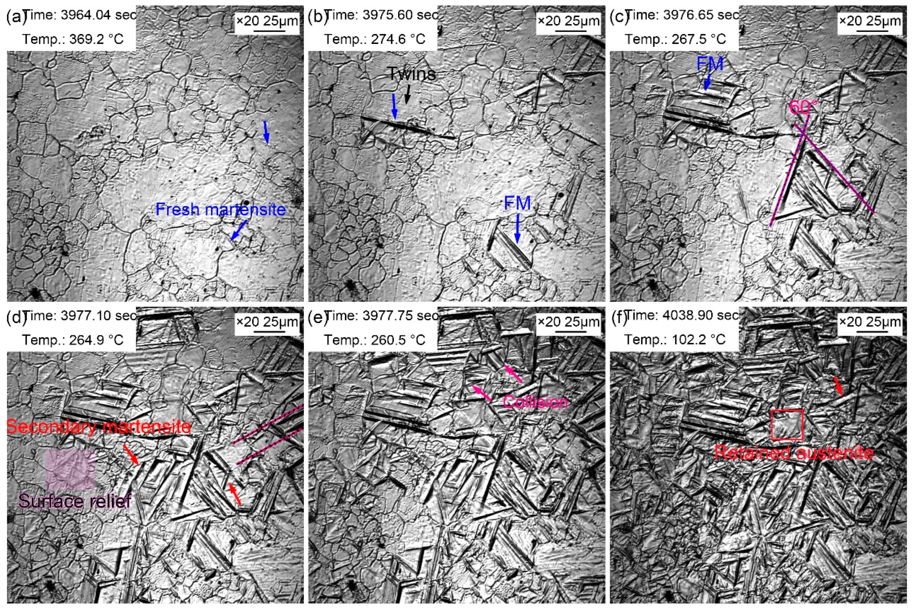
Figure 9 records the martensitic transformation during the cooling in the sample with a quenching temperature of 860 ℃. Martensite lath appeared, as shown by the blue arrow in
Figure 9a, when the temperature decreased to 369.2 ℃. This martensite was primary martensite, also called as fresh martensite (FM). The martensitic phase transition point (M
s) of the sample was about 369.2 ℃, while the M
s temperature of this steel was determined to be 340 ℃ by thermal simulation experiment. The difference in the initial temperature of martensitic transformation by two methods was resulted from that the effective M
s was obtained by thermal simulation experiment through the overall volume expansion effect of martensitic transformation, while in-situ observation determined the M
s just according to the temperature at which the martensite appeared in one certain grain. Generally speaking, the M
s determined by in-situ observation was higher than that reflected in thermal simulation experiments. This is because martensitic transformation did not start at the same time in all grains although the nucleation and growth of martensite explosively proceeded. In addition, martensite nucleated from the grain boundary and grew intragranular until stopped at the grain boundary. More and more martensite laths explosively appeared as the temperature decreased, and most martensite laths traversed the entire grain. Furthermore, some martensitic laths were found to nucleated and grown from the twins (
Figure 9b). Since the formed martensite stimulated the nucleation of the surrounding untransformed austenite, the austenite nucleated and grew in parallel after being provoked. Therefore, the martensite laths growing in parallel in some austenite grains. When the temperature decreased to 267.5 ℃, the martensitic laths appeared simultaneously with an angle of 60°. Besides, some martensitic lath synchronously formed paralleling to each other. More FM was found as the temperature continued decreasing accompanied by the secondary martensite (SM). SM referred to the martensite with slightly thin lath formed around FM, which appeared at a certain angle with FM (
Figure 9c). More and more surface reliefs due to martensitic transformation gradually appeared at parent austenite grain boundaries and fresh martensite as the increased volume fraction of martensite (
Figure 9d). Most martensite stopped growing when they encountered grain boundaries, and some martensite meet each other, which also stop the growth of martensite lath (
Figure 9e). The nucleation and growth of martensite were very weak when the temperature closed to room temperature. Most martensite transformation finished within 13 seconds, and the rate of martensitic transformation gradually slowed down. However, the distortion caused by martensitic transformation prevented the martensitic transformation in surrounding austenite. A small part of the regions was retained as residual austenite, in which the allocation of elements such as C in ferrite to residual austenite was mainly completed, due to the failure of martensitic phase transformation (
Figure 9f). The growth rate of martensitic lath was relatively fast, but the growth rate of longitudinal martensitic lath was faster than that of lateral ones. Although martensitic transformation explosively proceeded, but the martensitic transformation was not simultaneous. Martensitic transformation selectively started in the parent austenite grain, but this selective process was very short. Nevertheless, the temperature of the sample may remain unchanged or even slightly increase during the cooling process since martensitic transformation released more latent heat of transformation. Therefore, the isothermal martensite formation was inevitable. This latent heat caused by martensitic transformation was also one of the reasons for the selective initiation of martensitic transformation. The supercooling degree became smaller at a constant or slightly increased temperature, thus the martensitic transformation was inhibited. In addition, the selective initiation of martensitic was also related to the distortion caused by the martensitic transformation. The martensitic transformation in untransformed austenite was strongly inhibited by the surrounding martensitic transformation.
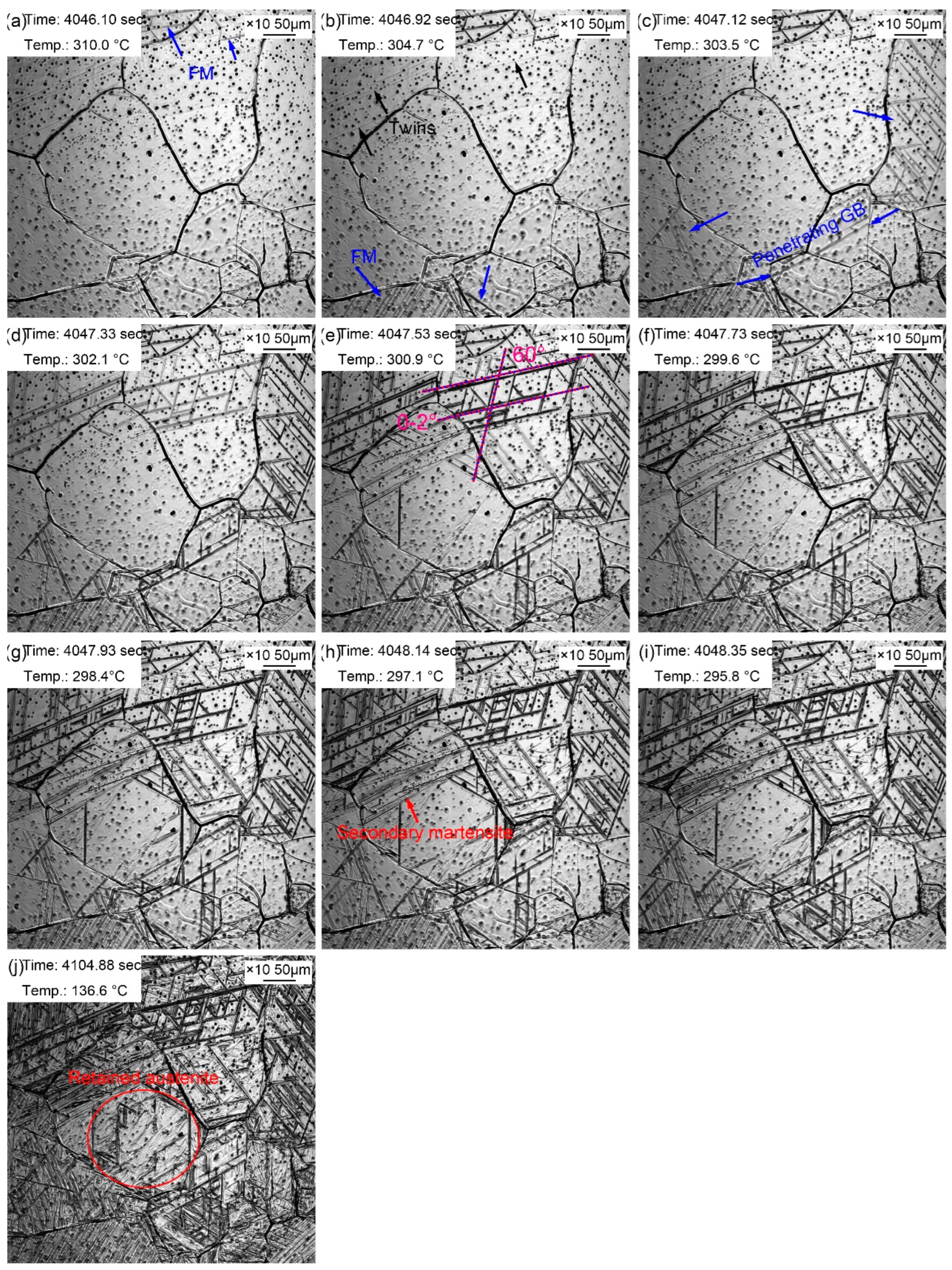
The martensitic transformation during the cooling process of supercooled austenite with a quenching temperature of 1160 ℃ is displayed in
Figure 10. Martensitic laths appeared at 310.0 ℃, as shown by the blue arrow in
Figure 10a. It is referred that the martensitic phase transition point M
s was about 310.0 ℃, which was lower than that in the sample whose quenching temperature was 860 ℃ (369.2 ℃). Generally speaking, the M
s temperature of martensitic transformation should be higher in a larger austenite. However, the results of in-situ observation of martensitic transformation were extraordinary. The possible reason was that the martensitic transformation observed by in-situ method was on the local of the sample surface, and its view field was limited. The unobserved view field may have undergone the martensitic transformation at a relatively high temperature. In addition, due to the martensitic transformation on the sample surface, it is difficult to unify the different starting temperatures of martensitic transformation due to the uneven composition caused by the evaporation of alloying elements formed during the heating process in austenite. More and more martensitic lath appeared as the temperature decreased. Martensitic lath nucleated from the grain boundary and grew intragranular until stopping at the grain boundary. However, it was accidentally observed that martensitic lath grew through grain boundaries in
Figure 10c. The grain boundaries that were passed through were relatively straight, which newly formed during the thermal holding. In addition, some martensitic lath nucleated and grew from the twins. The reason why twins acted as the martensitic nuclei was that martensitic transformation required structural and energy fluctuation. As a kind of crystal defect, twins provided large defect energy to meet the structural and energy fluctuation, to promoted martensitic transformation. Martensitic laths appeared simultaneously at a 60° angle, and some martensitic laths formed synchronously paralleling to each other. More and more FM and SM gradually increased with the decrease of temperature, in which the SM appeared at a certain angle with FM. Most martensite transformation finished within 2.25 seconds, and the rate of martensite transformation slowed down. However, the distortion caused by martensite transformation inhibited the martensite transformation in surrounding austenite (
Figure 10j). Martensite growth was a nondiffusion-free interfacial cooperative pushing process, and its specific volume was larger than that of austenite. Therefore, elastic deformation was caused accompanied by volume expansion during the martensite phase transition. And then large distortion energy formed, which hindering the further martensite transformation.
According to the in-situ observation of martensitic transformation, martensitic transformation in the same sample did not appear firstly in large size grains, then in small size grains, but appeared in the parent austenite grains in a seemingly chaotic manner. This may be explained by the differences in the size, composition, and defect density in austenite grains, which leading to the selectivity of martensite nuclei. In addition, the martensitic transformation was also affected by the completed martensitic transformation. For example, the region where the martensitic transformation occurred firstly inhibited the martensitic transformation of the surrounding austenite. And then a certain supercooling degree was required to provide the driving force for the martensitic transformation. Therefore, as the temperature continued decreasing, martensitic transformation began to proceed in other grains. This also explained the phenomenon that the martensitic phase transition increased gradually with the decrease of temperature in the in-situ observation. In addition, it can also be found that FM was larger than SM, and SM usually nucleated and grew attaching to the FM. Compared with the martensitic transformation in the sample at 860 ℃, the martensitic transformation process was faster, and the martensitic lath was longer at a quenching temperature of 1160 ℃. It reflected that the martensitic growth inhibition was less in the large parent austenite grains. Furthermore, the grains were coarser due to higher quenching temperature, thus the driving force of martensitic transformation was greater. And the migration rate of phase interface increased accordingly, so the martensitic transformation was faster.
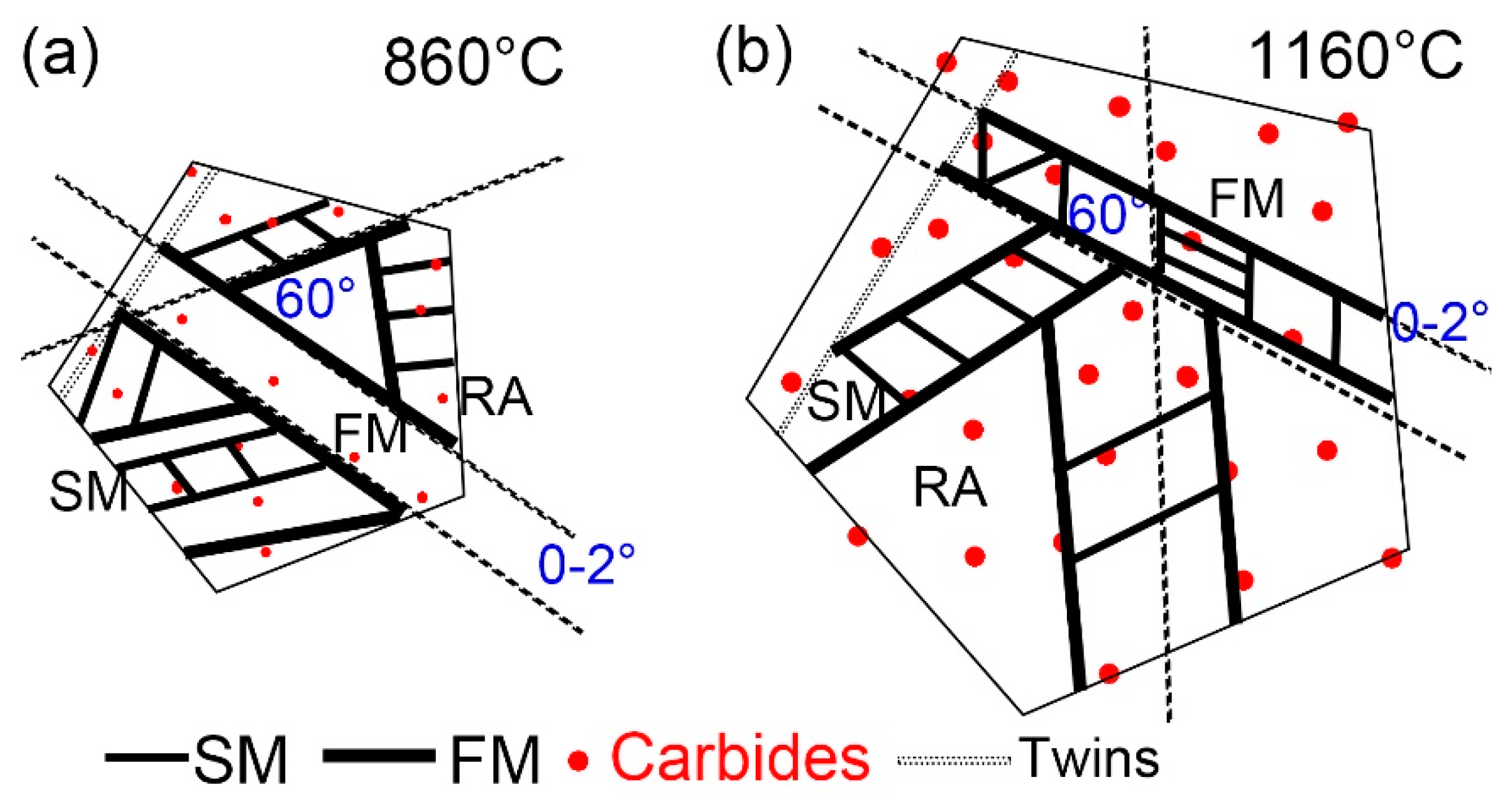
Figure 11 indicates the martensitic transformation of supercooled austenite at different quenching temperatures, which was summarized based on in-situ observation. Martensite nuclei did not occur synchronously during the quenching process of supercooled austenite, but selectively proceeded and increased in batches in some areas. This nucleation pattern divided untransformed austenite into multiple regions. In different regions, the size of firstly formed martensite (FM) was large, and the size of subsequent martensite (SM) was small. This is because the shape of martensite depended on the stress field between the nucleated martensite laths and other martensitic embryos. The parent phase austenite presented obvious different grain sizes at different quenching temperatures. In addition, the size and volume fraction of the coarsen second phase particles in the matrix increased with the quenching temperature.
Martensitic nucleation and growth in different parent austenite grains did not affect each other at the early stage of martensitic transformation, during which less martensite formed. The martensitic transformation gradually increased as the temperature decreased, and the martensitic laths restricted each other. In general, there were three types for martensitic nucleation. Firstly, martensite nucleated along the parent austenite grain boundary and grew intragranular until stop growing when it collided other martensitic lath or grain boundary. Besides, martensite nucleated at annealing twins, which had lattice defects and provided better structural and energy fluctuations. Moreover, martensite nucleated at the pre-formed martensite lath and grew into the austenitic grains at about 60° or 120° to form new martensite lath. The lath packet presented two styles: one was the parallel laths (0~2°) based on the pre-formed laths and another was the martensitic laths at 60° or 120° in the other direction stimulated by the pre-formed laths, finally forming the triangle, parallelogram or hexagon morphologies. The size of FM was larger than SM, because FM formed in the parent austenite without other martensite constraints, while SM only nucleated and grew in the area surrounded by other preformed martensite. The growth space of SM was severely restricted, and the martensite transformation resistance at this stage was greater, resulting in greater elastic stress between martensite laths and the smaller SM laths. The formation of SM laths also strongly inhibited the martensitic transformation of its surrounding untransformed austenite and promoted the formation of residual austenite.

