1. Introduction
The presented research article describes an implementation of a functionally graded shell-lattice structure in the lightweight design of a mechanical element based on the bicycle crank arm—
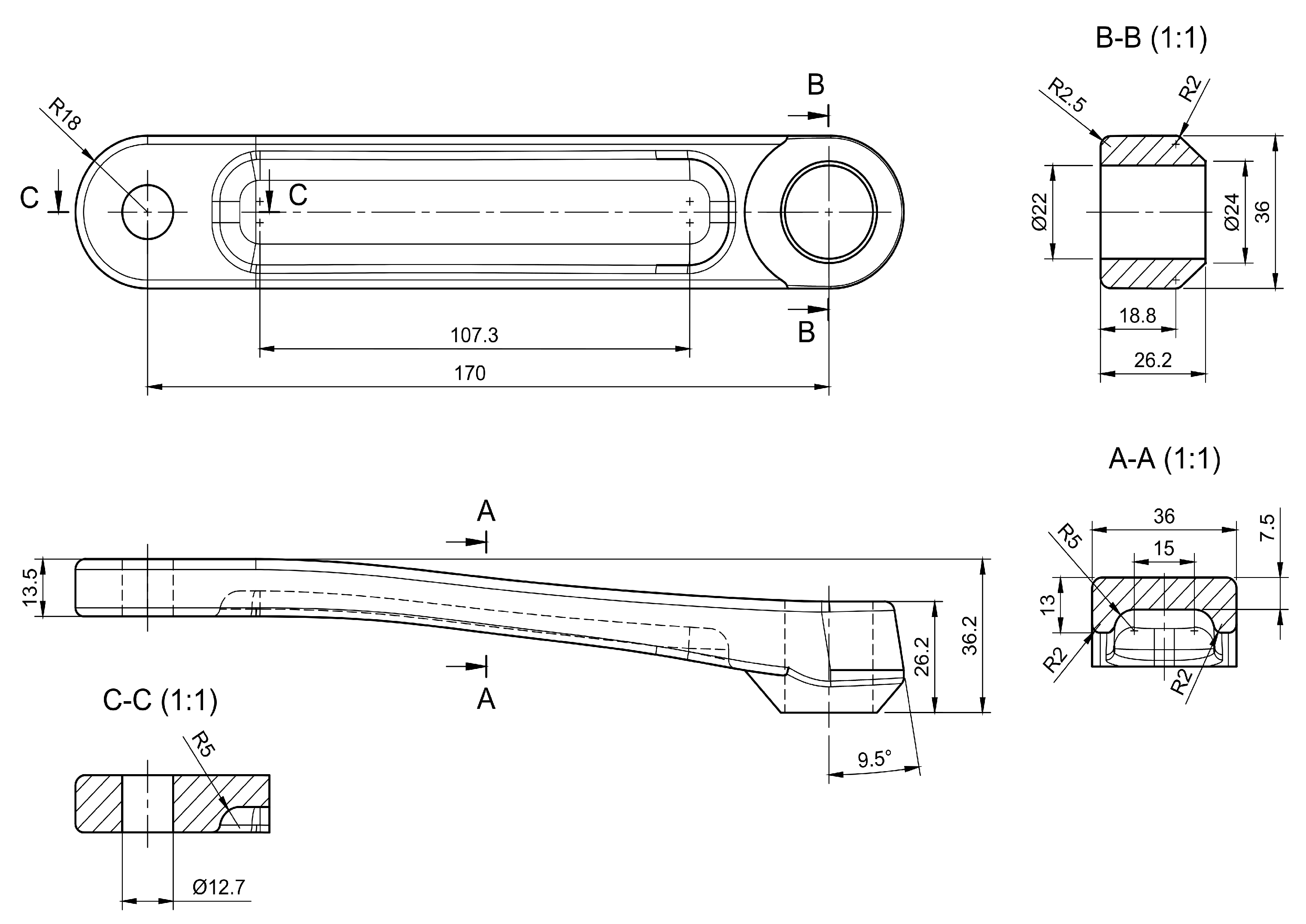
Figure 1. It is an example of a part where lightness is essential. The requirement of lightness of the structure regarding bicycle parts is self-evident since the vehicle is powered by human muscle power, and minimal energy input is desired. Through this publication, the authors want to prove that designing and manufacturing 3D-printed parts with the optimised internal infills as a functionally graded shell-lattice structure employing metal Fused Filament Fabrication (FFF) technology is possible and improves their structural performance. Thus, the authors’ efforts were principally targeted at answering the following questions:
How to represent the geometry of a 3D printed object with a functionally graded infill efficiently?
How to identify an optimal design among various attainable and include manufacturing constraints?
Does the developed part fulfil functional requirements?
Is manufacturing the part with a functionally graded infill workable in metal FFF technology?
Thus, a project’s primary outcome is a robust design process for additive manufacturing targeting the metal FFF method with the infill as functionally graded lattices. The metal FFF is often called the Material Extrusion method (MEX). It characterises that wire-shaped metal-containing plastic (filament) is plasticised in a nozzle and selectively put layer by layer locally, building a 3D part, which is sintered, receiving a finished metal part [
1]. A main benefit of the metal FFF technology in the project’s context goal is the possibility of creating complex parts without a need to add powder-release channels for loose powder from internal cavities.
Any internal structure of the 3D printed objects called an infill, was an optimised item. The infill usually has regular structures determined in slicing software as a total volume percentage. The infill structures determine the mechanical properties of the printed parts and impact the printing process [
2]. More material in the infill leads to generally a more robust but heavier object and extends the print time. As the infill, very promising structures are shell-based lattices because of their stiffness, strength and printability. Therefore, the authors implemented one in the crank arm. A selection of the lattice type was based on a literature review. So many researchers have been working on the mechanical responses of the lattice structures in recent years [
3,
4,
5,
6,
7,
8,
9]. However, their projects have focused mostly on specimens or simple parts with basic load cases - compression or/and tension. Unfortunately, attempts were missing to show how to benefit from those structures in functional parts with complex stress states that cannot be simplified to only tension or compression. The shown work fills this gap by demonstrating a real part’s investigation/optimisation process. As a result, the authors used a Gyroid shell lattice for the internal functionally graded infill, mainly considering its stress concentration-free characteristic, sufficient stiffness and printability.
Further, the article’s text presents the background research to explain the applied methodology and present the status quo. Next, in the Material and Methods section, the analysis method is described with the level of detail required to reproduce the analyses. The authors also present assumptions that were made, models, and material properties, giving all data. Subsequently, in the Results and Discussion sections, obtained results and comparison with existing designs highlight the achieved structural performance. Findings are discussed, focusing on structural performance and the developed methodology. Lastly, the authors summarised the work in Conclusions and proposed further directions for the planned investigations.
1.1. Lightweight Constructions
Lightweight constructions are characterised by low material density and unique methods of shaping and specific manufacturing, and all are implemented to achieve maximum stiffness at a given weight and strength. Lightweight and ultra-light structures are critical due to reducing machines’ energy consumption and sustainability. The main obstacle to the increased use of lightweight parts is cost pressure in individual industrial sectors [
10,
11,
12]. However, the future of creating new lightweight products looks very encouraging because of the increasing demand for such products in the last few years. This trend is fostered by the rapidly developing new additive manufacturing production technology.
Understanding natural structures are fundamental to designing lightweight designs effectively. In nature, lightweight objects have been ubiquitous for millions of years and have improved over these years. Natural creative processes based on the efficient use of resources have built structures unrivalled for us in many ways. For instance, in the bones of living beings, there is a mechanism causing the bone structure to grow in locations with high cycling strain and disappear where the strain is low [
13]—that remodelling occurs in bone mass and architecture due to stimuli obtained from its mechanical environment. That mechanism creates structures with different densities depending on external loads. Plants have also developed lightweight structures through natural evolution; bamboo is an excellent example. The bamboo stem has an optimal solution for strength and stability for specific environmental conditions. Bamboo is a nature-designed functionally graded material because the fibres’ volume fraction increases radially from the inner to the bamboo stem’s outer surface [
14].
However, engineers can achieve the lightness of designed objects by employing different techniques, namely lightweight and high-strength materials, new design and analysis methods, and changed or new manufacturing technology. A decision on which strategy to use depends on many aspects of particular development needs. This project aimed to mimic nature in design (biomimicry) by employing exploration methods in the design phase and the metal FFF in manufacturing.
1.2. Additive Manufacturing
Additive Manufacturing (AM) processes give engineers the most design freedom and produce physical objects from a computer model, creating layer-by-layer material systematically until the whole object is created without any shaping tools. AM technologies have several methods: binder jetting, directed energy deposition, material extrusion, material jetting, powder bed fusion, sheet lamination, and vat polymerisation. A brief review of the entire AM technology can be found in the article [
15].
A specific metal AM technology was chosen for the project: metal fused filament fabrication. That technology allows us to maximise benefits from the optimised internal lattice structure. The main advantage is that it allows the creation of complex infills without adding power-release channels (it does not require removing unsintered, loose powder from internal cavities formed by the internal structures), and most important, it is very cost-competitive [
1]. That process belongs to the extrusion method, and it is based on a standard FFF method for polymers, also known as Fused Deposition Modelling (FDM). In this method, metal powder bound in plastic is printed layer by layer into the object’s shape. The object size is scaled up to compensate for shrinkage during sintering. At that stage, the printed part is soft and brittle (green part). The printed part can then go through a washing stage to remove the binder or directly to the sintering process. Finally, the object is sintered in a furnace to fuse the metal powder into solid metal. The metal part is created as the process’s results and can be treated like any other metal part. Unfortunately, the technology is still in development, and many issues exist, such as print size limitation, available materials and the printed object strength [
16].
1.3. Infill as Functionally Graded Structure
Functionally Graded Materials (FGMs) are materials endowed with spatial variations in the physical properties and chemical compositions, which act as functional qualities. The FGM idea was proposed in the 1980s by Japanese researchers [
17], who developed a new class of composite materials for aerospace applications dealing with very high-temperature gradients. FGMs can be artificially created or formed by natural evolution. The examples of bones and bamboo show natural functionally graded materials [14]. Designed FGMs are used nowadays in different industries: machinery [
18], medicine (implants) [
19], aerospace [
18], etc. FGMs are very often cellular materials, which include foams and lattices. Their cellular characteristic can be observed differently depending on a scale: nano (1A–1µm), micro (0.1µm–1mm), and meso (0.1mm-10mm). In the presented work, the internal structure - the infill has functionally graded properties through the variable thickness. However, their variations are on a millimetres scale, and therefore it would be better to name them Functionally Graded Structures (FGS) [
7] instead of FGMs. The use of mesoscale is determined by the current capability of the metal FFF technology.
Designing functionally graded structures requires complex optimisation methods with considerable effort because of a high dimensionality of a model representation causing high computational costs [
20]. However, as it is shown in [
20] and [
21], it is feasible to design and create functionally graded materials efficiently. The authors showed in the article [
20] the novel general structural optimisation method—particle swarm optimisation, a nature-inspired optimiser, for parts with functionally graded material properties. Their numerical simulations presented that the proposed approach is practical, flexible, and computationally efficient for FGM optimisation problems. The developed optimiser outperformed classical mathematical programming-based optimiser, and the proposed approach is applicable to FGM objects with 2D and 3D geometries and any heterogeneous feature tree structure as a model of FGM variations. In the book [
21], the authors give an excellent overview of FGM detailed material mechanics, modeling, applications, and manufacturing methods.
In this work, we focus not on the FGM materials but on the functionally graded structure— the infill of 3D printed objects to mimic natural constructions of bones. In this research area of interest, there is a recent article [
22] in which the authors propose a new approach for generating bone-like porous structures. The paper proposed a novel formulation for generating porous structures based on structural optimization considering the optimum design from a mechanical perspective and analysing it through detailed parameter studies. The method is an extended voxel-wise topology optimisation algorithm, which maximises the mechanical stiffness by optimising the distribution of a given amount of material in a specified design domain under a given set of external loads. The authors successfully show the optimised 2D and 3D infill, including a manufacturing constraint—a minimum feature size. The authors did not focus on manufacturing constraints like overhang avoidance and closed voids containing unsintered powder in Selective Laser Sintering (SLS) for plastic materials. The work showed that it is possible to generate the optimised infill for bone-like structures SLS printing technology.
The next exciting work related to the presented project is the article [
2]; the authors investigated numerically and tested 2D and 3D biologically inspired infill patterns in cylindrical tubes. The infills were defined in a geometrical form of Gyroid, Schwarz D, and Schwarz P surfaces. The authors found that 2D (honeycomb) infills, such as rectangular or hexagonal lattices, are unsuitable for structural applications with complex 3D geometry because of the resulting imposed anisotropy. In the case of loaded and supported classical structural elements (when a 2D infill pattern is aligned with the principal stress orientation), 2D infills may outperform 3D infills. The authors also proposed optimising a local infill density based on the actual stress fields and performance requirements, modifying an infill wall thickness to achieve uniformly distributed stress. That idea was somehow realised in the presented work showing that it is feasible for metal FFF printing. Inspired by these articles, we decided to use the general, robust and affordable method of analysis of the functionally graded infill of the crank arm, namely design exploration.
1.4. Design Exploration
Design Exploration (DE) or Design Space Exploration (DSE) [
23] is a computer-assisted approach to arriving at an optimal design solution. Design space exploration must be performed carefully because a large complex system may admit millions, sometimes billions, of design alternatives. Therefore, a manual approach to DSE is unachievable. It consists of the following elements: a representation of design space, an analysis equipped with computer-assisted techniques for discovering potential design candidates, and an exploration method for exploring many design candidates [
24]. Therefore many procedures are included in the design exploration; they are the design of experiments (representation), response surface modelling with optimisation (analysis), and data mining (exploration method). These tools enable us to explore, understand, and improve the design before a conceptual phase of product development. The author used the DE for the presented problem to get a set of optimal designs. The implementation of DE is described fully in
Section 2.6 to avoid limitations here.
1.5. Lattice Types
Many researchers investigated different types of lattices/ cellular materials and their possible applications, including structural components [
25], energy absorption [
26], heat exchange [
27], and biomaterials [
19].
In the context of application in lightweight structures, it is known that the best option for lightweight constructions is to use stretching-governed lattice structures (strut-lattice types) based on Maxwell’s stability criterion [
28,
29]. Indeed, the necessary condition for strut-lattice systems to be stretching-dominated is that connectivity that the unit cell of the structure satisfies Maxwell’s criterion for static determinacy [
28]. The stretching-governed structures are expected to be about three times as strong as the bending-governed ones [
28]. As shown in [
28], the deformation of most foams, whether open or closed cells, is bending-dominated.
The previous work was preceded by an analysis of strut-lattice implementation in the identical crank arm, as presented in the article [
30]. This article shows the practical application of beam-based functionally graded lattice structures using a blend of manual adjustments and numerical optimisation methods similar to those presented in the current work. Theoretically, the conclusions were that implementing the functionally graded lattice structures (strut-lattice) in the crank arm, combined with high-performance materials, significantly improves the typical bicycle’s stiffness crank arm. However, the result holds limited validity due to the uncertain material properties of stainless steel 17–4 PH produced via 3D printing technology.
The article [
2] is an example where the authors analysed the infills as a geometrical form of Gyroid, Schwarz D, and Schwarz P surfaces, which can be treated as a bending-dominated internal structure. The authors built the infill with a Triply Periodic Minimal Surface (TPMS). TPMS is a minimal 3D surface, meaning a surface that locally minimises its area; in other words, it has a mean curvature equal to zero at every point[
2]. TPMS is periodic, continuous, non-self-intersecting, and infinite. Some of these surfaces are known enough to associate their names, such as Schwarz primitive, Schwarz diamond, Schwarz hexagonal, Schwarz crossed of parallels, Neovius, and Gyroid.
The gyroid surface and shell lattices based on the gyroid structure were discovered by Schoen [
31]. The 3D model of the TPMS gyroid surface geometry can be described using the expression (
1).
Where x, y, and z are spatial coordinates,
is the unit cell’s length, and t is the level parameter of the isosurface, which can effectively control the relative density of the gyroid surface [
31].
Gyroid-based structure characterises low-stress concentrations due to zero mean curvature - no joints or discontinuities [
32]. Moreover, it has no planes of symmetry and no embedded straight lines, which is beneficial when filling complex geometry regions. Moreover, as shown in [
33], the gyroid infill is nearly isotropic, simplifying the implementation of gyroids into design and optimization workflows. Low anisotropy under compression of the gyroid infill structure was also confirmed by [
34]. Moreover, it was noted that the inner gyroid structure and pattern are more relevant than the material used to build the structural part. In recent years, TPMS-based lattices have been proposed for various engineering applications: body implants, functionally graded structural lattices, heat exchangers, and lightweight structures for mechanical components [
35]. Furthermore, functional grading TPMS lattice can be used with a proper design to mimic the structure of natural systems [
36,
37]. Therefore, we assumed that the gyroid lattice infill is an excellent choice for a 3D printed infill of complex lightweight parts.
1.6. Crank Arm Design and Analysis
The crank arm design was a topic for many authors. They have used it for investigations with Finite Element Analysis (FEA) and structural optimisation [
38,
39,
40,
41]. Most of the time, the crank arms had a standard form known from the daily usage of bicycles. However, one can see an innovative crank arm design for additive manufacturing [
39] designed using topology optimisation to maximise stiffness at minimum mass employing a finite element method. In the context of manufacturing, crack arms are primarily designed for forging and casting for purely economic reasons. However, for high-tech applications, they are made of carbon fibre composites. Materials for the crank arm are typical for lightweight structures, aluminium alloys, steel alloys, carbon fibre composites, and titanium. Nonetheless, bicycle crank arms are manufactured mainly of aluminium, fibre composite, and steel alloys. Material selection depends on bike types, targeted customer groups’ applications, and manufacturing costs. Due to the variety of materials, the stiffness-to-weight ratio of the cranks is highly variable.
2. Materials and Methods
2.1. Analysis Method
Several tools to design 3D models exist, but not all can effectively create components with a lattice structure, mainly because of a lack of robust lattice generation methods and their proper representation in existing CAD systems. The manual process of building lattice models using existing CAD software is always very cumbersome. However, the software - nTopology (nTop) [
42] can give some freedom in the design of the lattices, but exporting to CAD can be done only via Standard Triangle Language (STL) format, which is very inconvenient for further integration with other solids. We selected it for the project nTop since it has all the needed lattice generation capability and a sufficient interface to export the lattice model. However, our optimisation problem could not be performed in nTop because of the existing limits of the implemented optimisation procedures. Therefore, HyperMesh and HyperStudy software and programming were employed. The developed process is presented graphically in
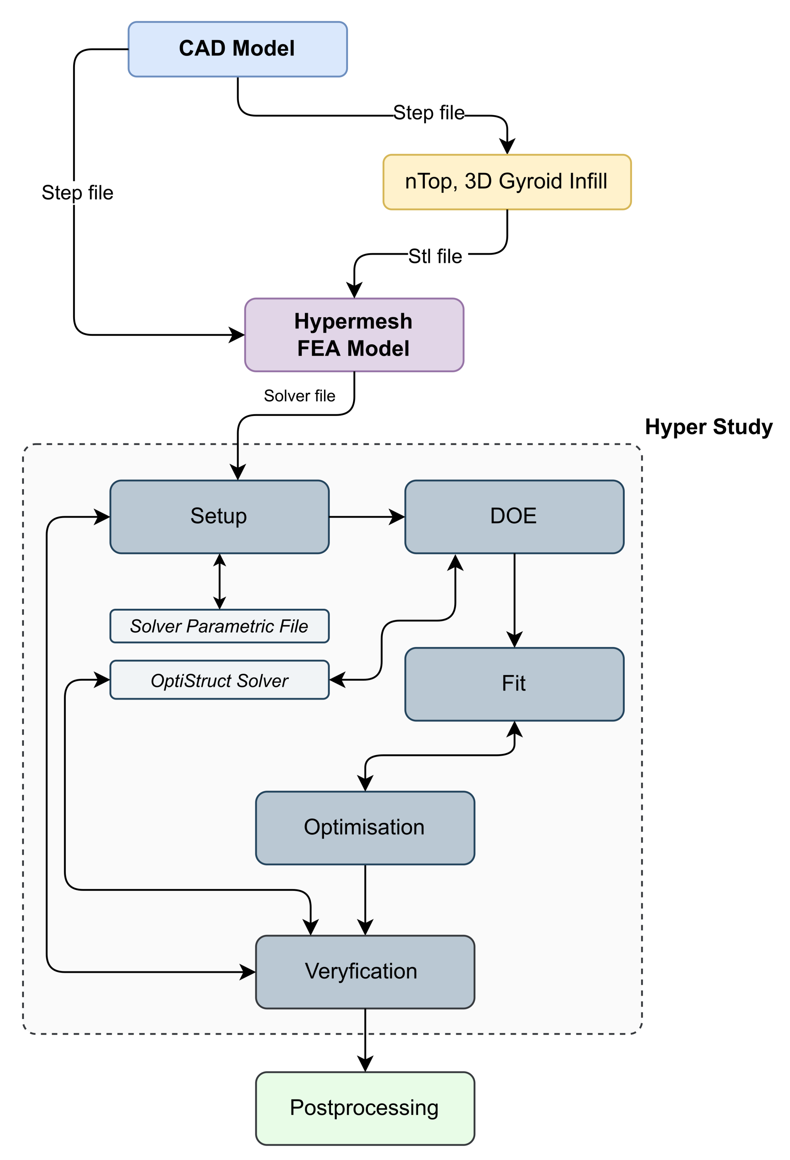
Figure 2. The design process started with creating a 3D CAD model; then, a Gyroid infill lattice was created employing nTop. Next, a shell body and the generated infill were served to build a finite element model in HyperMesh. After that, the FEA model was an input for the design exploration (DE) module, resulting in an optimum design of the lattice infill according to a defined optimisation problem. In the last step, the infill as the optimum graded lattice and the shell body were combined in one solid using HyperMesh and nTop, resulting in an STL file of the print-ready model. The following text describes the details of each stage.
In order to compare the results of the optimised design with reference models, additional FEA models were analysed. So, four models were built using the same conditions as in the case study. These reference objects were a hollow crank arm model with no infill and two models from previous publications [
30], which have the same dimensions as the optimised one but two different infills made of Face-Centred Cubic (FCC) and (Re-entrant) strut-lattice and last one the original Shimano FC-R450/453 model.
2.2. Loading and Assessment Criteria
Typical loading of the crank arms coming from pedalling is dominated by bending into two perpendicular planes and torsion. The loading is standardised by an ISO standard [
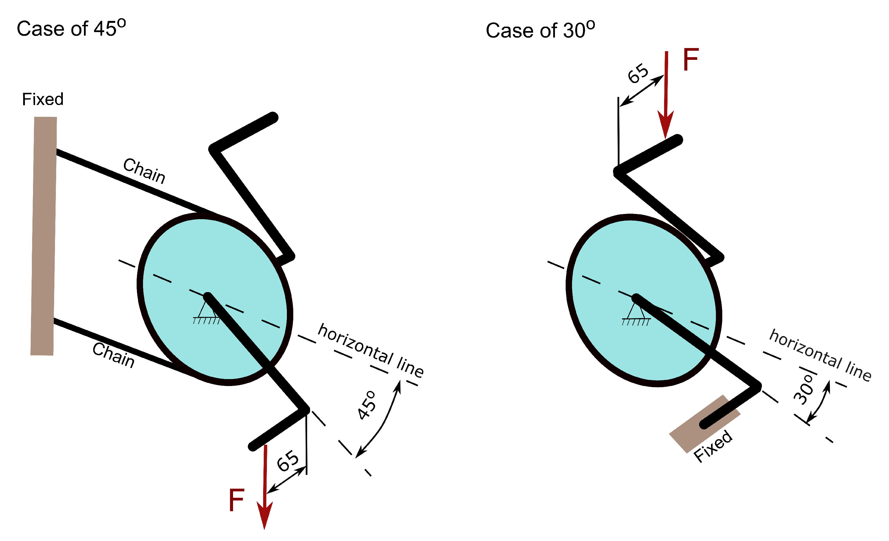
43] for design purposes, splitting it and two loading groups—two fatigue load cases. Vertical force of 1300N or 1800N is required by the standard with test cycles of 100000 or 50000, depending on the bicycle application. The load is applied on a pedal (offset of 65mm from the outboard face of the crank arm). The direction of the crank arm with respect to horizontal direction is 30°or 45°, as shown in
Figure 3. The greatest fatigue force of 1800N of the 45°load case is defined for mountain and racing bicycles with cycling requirements of 50000 and 100000 cycles, respectively. For the 30°load case, only one force of 1800N is mandatory with the test cycles of 50000. The obligatory load values of the standard appear conservative compared to the test data shown in the article[
44]—a 34-year-old healthy man can generate during 2min on a bicycle power of 200W with a rotational speed of 50rpm. Therefore, he generates a torque of 38.2Nm and considering the crank arm length of 170mm, it translates to the force at the pedal of 225N. The observed significant difference in the forces can be explained by the desire to ensure safety under all conditions. For example, when the force is applied dynamically by jumping on the pedal. In the presented work, only one fatigue load at 45°—
Figure 3 with a maximum force of 1800N is analysed since it is the most severe case for this crank arm.
Proper fatigue analysis can significantly complicate the whole design exploration process, causing the optimisation results to be incorrect due to a mesh-sensitive fatigue model and the difficulty in result interpretation. Moreover, the fatigue endurance of a printed object is very dependent on the printing process parameters [
16]. Consequently, a simplified assessment criterion was defined by a von Mises stress limit of stainless steel 17–4 PH of 360MPa. The author accepted that the chosen limit of von Mises stress is sufficient, considering the printed material strength [
16] and the fact that the infill has extra small fillets of 0.35mm that were not present in the FEA models because their implementation was practically impossible due to the complexity of the infill geometry. Nevertheless, fillets were applied in the stage of the infill assembly with the crank arm body in nTop software for printing preparation.
2.3. Infill as Surface-Lattice Structures
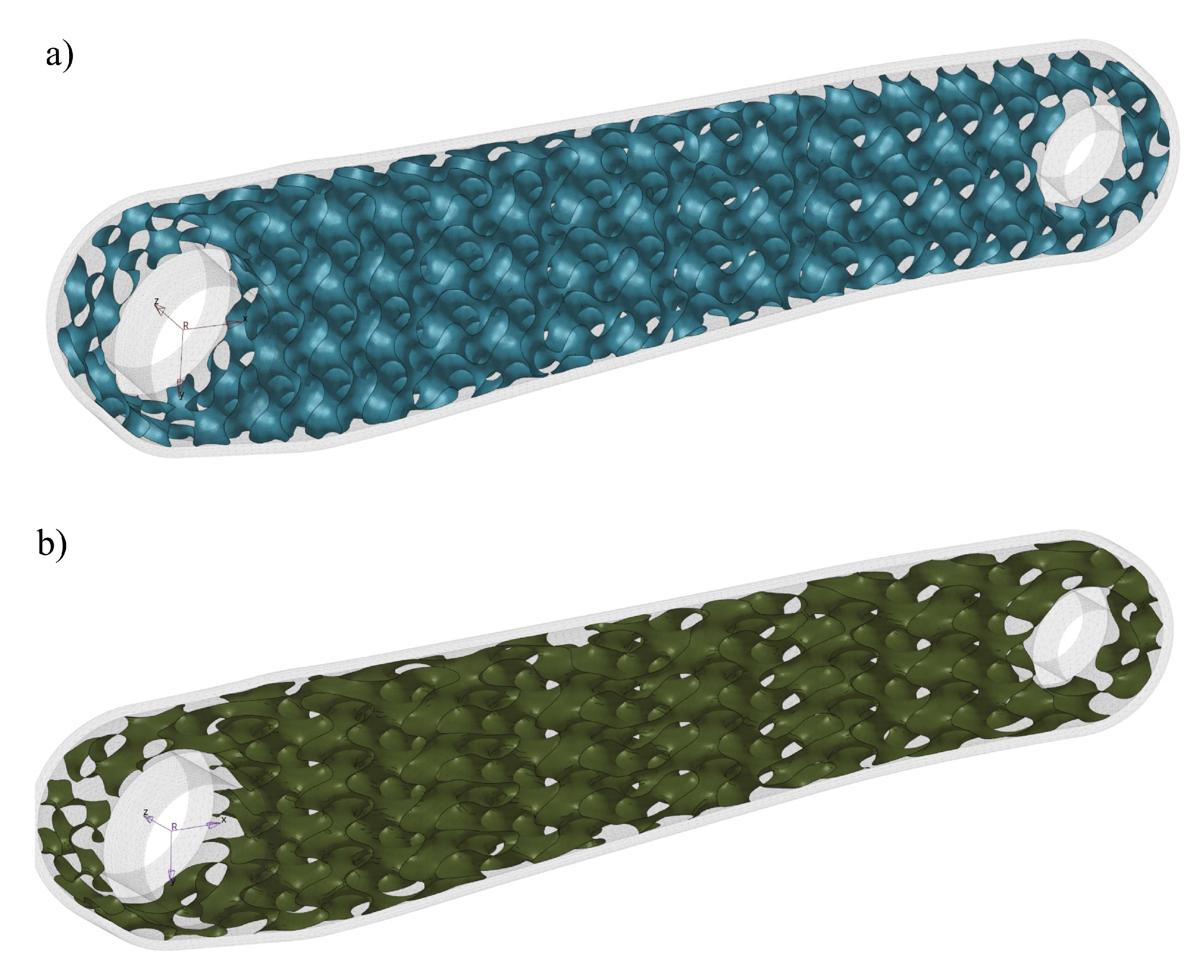
The selected lattice structure is the Gyroid TPMS with two different cell sizes: 10x10x10mm (X, Y, Z) and 18x8x10mm (
Figure 4). The authors used the shell lattice with two unit cell sizes and varying thicknesses. As a result, optimal spatially varying shell-lattice structure thickness was found to create the functionally graded infill. The cell size has been chosen to achieve a self-supporting infill structure and avoid closing the cell due to its size in the printed element. As a rule of thumb, an overhang that extends at a 45°angle requires extra support to make it possible to print the structure. Reorientation of the printed object can help to minimise the overhangs. Nevertheless, the proposed infill ensured a print without extra internal support. Unfortunately, the cell size selection limits possible design candidates for the infill.
The initial thickness pattern was identical for both lattice types. The pattern Equation
2 was selected based on the assumption that the crank arm must be symmetric and cantilever bending with torsion is the dominant loading. The defined pattern corresponds approximately to the stress distribution during pure bending. Generally, any thickness pattern is possible, and the selection also limits potential design candidates for the infill. The pattern parameters (
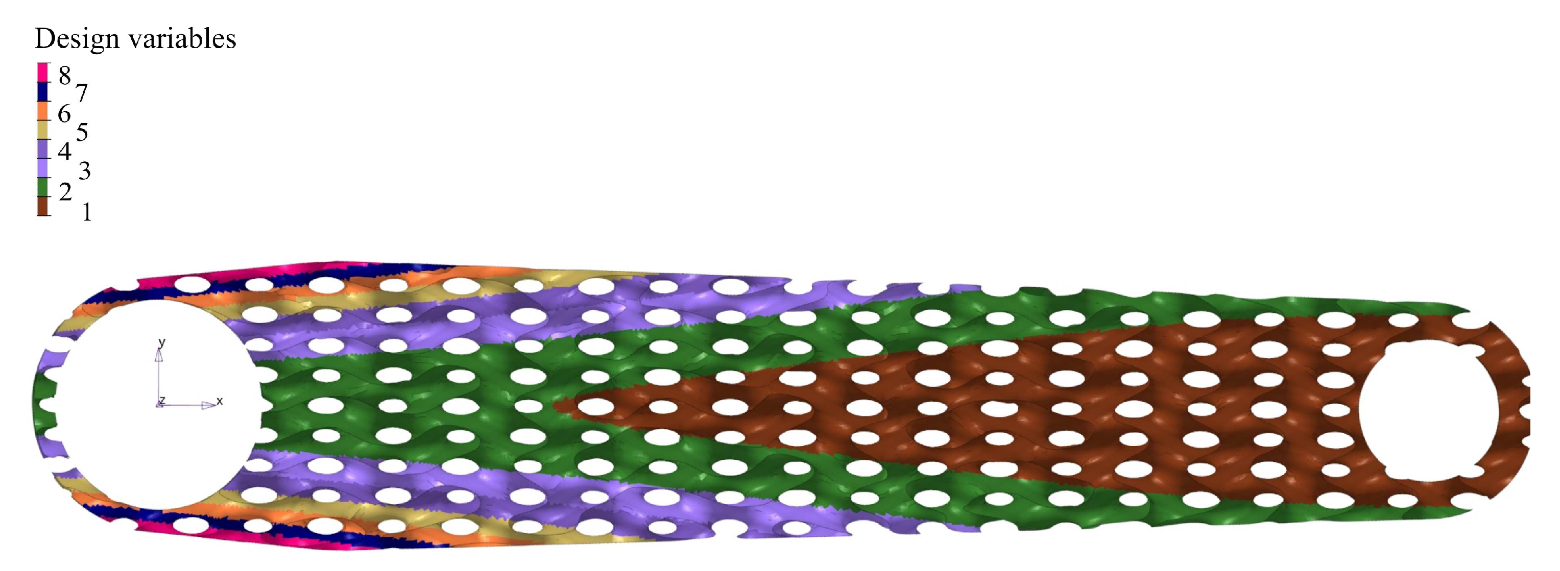
Figure 5)—a thickness variability has been limited to 8 design variables to minimise the computational time. The thickness distribution was obtained by dividing a thickness range defined by Equation
2 into eight groups; the average group thickness is assigned to the group elements. This action helped reduce the design variables; each variable had a continuous range of variation of 0.5–1.5mm. The minimum thickness was driven to the resolution of a 3D printer nozzle, while the maximum thickness was restricted by the desire to achieve a recognisable post-print structure of the lattice infill. Too small a cell size could cause a complete closing of the space in the cells in some parts of the infill where maximum thickness is required.
The initial thickness distribution function shown in
Figure 5 is defined as follows by the equation:
Where x, y, and z are spatial coordinates and -thickness distribution in mm.
The arm concept was chosen as a shell body with a thickness of 1.6mm with the presented functionally graded infill. The shell body thickness was selected, considering that a printer nozzle size for the metal FFF technology can be 0.4–0.6mm. A thinner wall can cause manufacturing problems with the representation of the wall thickness properly. The thicker wall can lead to an unwanted increase in the mass of the printed object.
2.4. Manufacturing Constraints
Manufacturing constraints can depend on the specific metal FFF technology. Currently, there are some available commercial solutions; the first one is Markforged with Metal X system [
45], the second one is BASF—Ultrafuse [
46], the third one is Virtual Foundry [
47], and the last one is Desktop Metal’s Studio System [
48]. In the presented project Metal X system was used to produce a design part, and consequently, the following manufacturing constraints need to be considered in the design process:
The material strength of the green parts determines the required support structure and limits the possible types of internal shell-lattice structures;
The sintering process limits the size of the printed parts and forces to use of support structures;
The printed material and nozzle size determines the minimum thickness of a printed object;
Metal X technology offers only some materials to print: 17–4 PH stainless steel, H13 tool steel, A2 tool steel, D2 tool steel, Inconel 625, and Copper, whereas 316L stainless steel, titanium Ti6Al4V and aluminium are not available for this system;
A substantial shrinkage after sintering reached approximately 20%, varying in a small range depending on part sizes;
The material is characterised by high porosity due to the specific production process;
Material show strength anisotropy determined by a part orientation during printing.
The authors selected the filament developed by Markforged, stainless steel 17–4 PH (version 2) for the presented project, offering theoretically sufficient strength. As mentioned, bicycle crank arms are manufactured mainly of aluminium, fibre composite, and steel alloys. Therefore, the material selection does not seem unusual for the application.
2.5. 3D Printing, Debinding and Sintering parameters
The crank arm made of 17–4 PH (version 2) stainless steel was manufactured using the Markforged Metal X system (printing time of 2d 4h) with the settings shown in
Table 1.
The debinding and sintering processes were done in-house with the default parameters developed by Markforged [
46]. The Wash-1, a solvent-based debinding system with Opteon SF-79 liquid, was utilised to debinding the green part for 1d 8h. For the sintering, Sinter 1, a tube furnace was employed to produce the 3D-printed crank arm.
2.6. Design Exploration
The design exploration methodology was employed to find the design’s best possible configuration by modifying the design variables in a design space. The DE analysis was conducted using HyperStudy [
49] software, the OptiStruct [
50]—a finite element solver and Multiobjective Optimisation (MOO) [
51], and other auxiliary tools for data analysis. To begin this process, eight design variables—the lattice-shell thickness pattern were selected, as shown in
Figure 5, based on the distribution described by Equation
2. Those variables and other parameters were implemented in an input file of the OptiStruct solver via its parametrisation that allows an optimisation process. Once the finite element model and the design variables were established, design objectives were defined as mass and maximum displacement. We decided to use MOO, minimising the objectives with a design constraint defined as von Mises stress of 360MPa. Since we had set it as multiobjective optimisation with two contradictory objectives to minimise the total mass and the maximum deformation, the design exploration gave not one but a set of optimal solutions.
Once the DE model was set up, the Design of Experiments (DOE) was employed as prerequisite steps for an approximation stage, fitting a predictive mathematical model to the data to create a response surface model approximation see
Figure 2. The DOE study’s objective was to distribute the design points uniformly in the design space to feed them into a fitting method to predict the model behaviour accurately. The Modified Extensible Lattice Sequences(MELS) method [
52] was employed for the DOE studies. MELS is a quasirandom sequence designed to distribute the design points in space, minimising clumps and voids evenly, and is based on extensible lattice sequences [
53]. The fitting process used the Fit Automatically Selected by Training (FAST) method [
52], allowing the building automatically best-fitting functions by testing all implemented methods. Then, instead of finite element analysis, that built approximation was utilised to shorten the optimisation process time avoiding typical problems with limited computation resources. Following appropriate procedures, the MOO step was employed. The Global Response Search Method (GRSM) [
52] was used for optimisation. The algorithm generates a few designs, including global sampling, to ensure the right balance of local and global search capability. The response surface is updated with the newly-generated designs to improve the model fit then response surface-based optimisation is conducted. As a result of the described process, the non-dominated solutions (Pareto-optimal set) are determined. Here is where the entire analysis process ends, and the optimum solutions were selected, considering other factors that could not be considered during the DE process, in this case, 3D printable constructions.
2.7. Finite Element Model
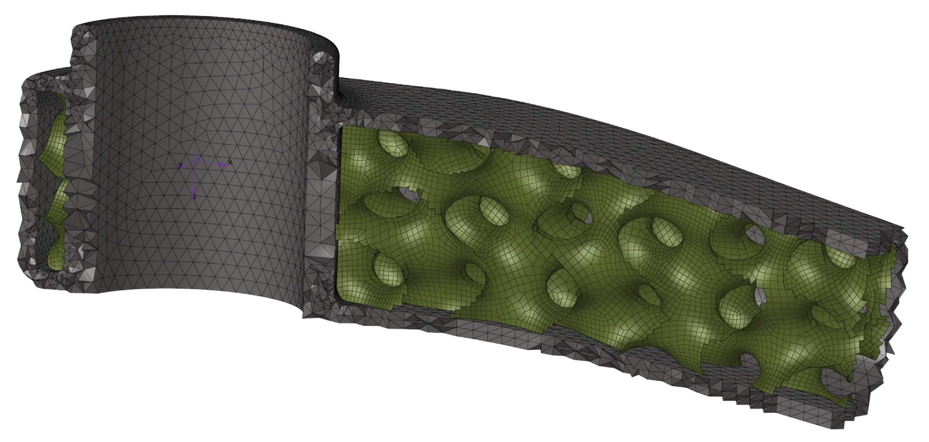
We built a crank arm finite element model using two elements: second-order 10-tetrahedron elements and first-order shell quad elements (
Figure 6). The OptiStruct solver was employed to analyse the developed model. Since the deformation of the part is expected to be small with stress below the yield strength, the FE analysis is linear, allowing for a shorter optimisation time. However, the model linearity does not limit the generality of the proposed method in any way. The shell model of the internal lattice infill allowed us to parametrise the models required for the design exploration phase. Contact elements connect the external solid elements with the shell elements of the infill
Figure 6. The initial lattice thickness distribution was defined, as illustrated in
Figure 5, applying eight design variables (shell element thickness). For that purpose, a computer program was developed that assigns a particular thickness to the shell elements with a defined number of the variables based on the given equation Equation
2. The reduced number of parameters contributed to the simplicity when optimizing and generating a final STL model. However, increasing the variables at the cost of additional modelling complexity is possible.
2.7.1. Load and Boundary Conditions
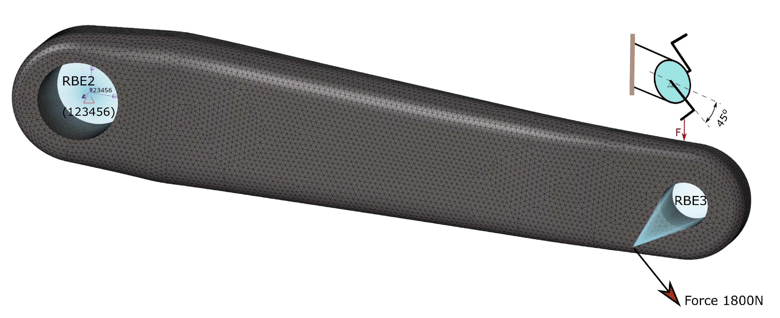
As we described earlier, only the load case of the fatigue at the crank arm location of 45°, with a maximum force of 1800N, is analysed since it is the most severe case for the designed crank arm. The force was applied using the rigid body element type 3 element (RBE3), and the crank arm was fixed using the RBE2 element, as indicated in
Figure 7. The drive (independent) node of the RBE2 element was created in the centroid of the large hole used to fix the crank arm of the shaft. All degree of freedom of that node was fixed. The force offset of 65mm from the outboard face of the crank arm was used to simulate a realistic load condition—the force needs to be applied in the middle of a pedal. Thus, the force was applied at the drive (independent) node linked with the driven nodes of the small hole via the RBE3 element.
2.7.2. Contact
The solid and shell elements are connected via contact elements; all degrees of freedom of nodes of both element types are bounded via a contact penalty algorithm. Freeze contact interface is used, which enforces zero relative motion on the contact surface, and the rotations at the slave node are matched to the rotations of the master patch. The Freeze contact type is predefined in the OptiStruct solver as one of the offered contact types.
2.7.3. Materials of Models
As discussed, we selected 17–4 PH (version 2) stainless steel as the material for the crank arm. Version 2 of the material means the updated 17-PH filament for better printability. The alloy is available for the metal FFF technology produced by Markforged. The mechanical properties of the chosen material as printed are presented in Tabele
Table 2. The data comes from the Markforged document [
54] and the articles [
16,
55], where the properties have been experimentally verified, and as we can see in these publications, the 17–4 PH steel is very brittle as printed with varying strength caused by material defects. In the article [
16], the authors argue that applying the metal FFF technology for structural parts is risky. Even so, the choice of FFF metal technology for the current project is enforced, as it allows parts to be manufactured without trapped metal powder inside the infill. The technology still offers a high potential for further development.
Seeing the large spread of material properties and existing anisotropy of material caused by the printing, we decided to select the properties shown in Tabele
Table 3. for our research and used a linear isotropic material. Additionally, one of the reference models was the original Shimano FC-R450/453, made of wrought aluminium alloy, and its properties are listed in
Table 3.
3. Results
3.1. Design Exploration
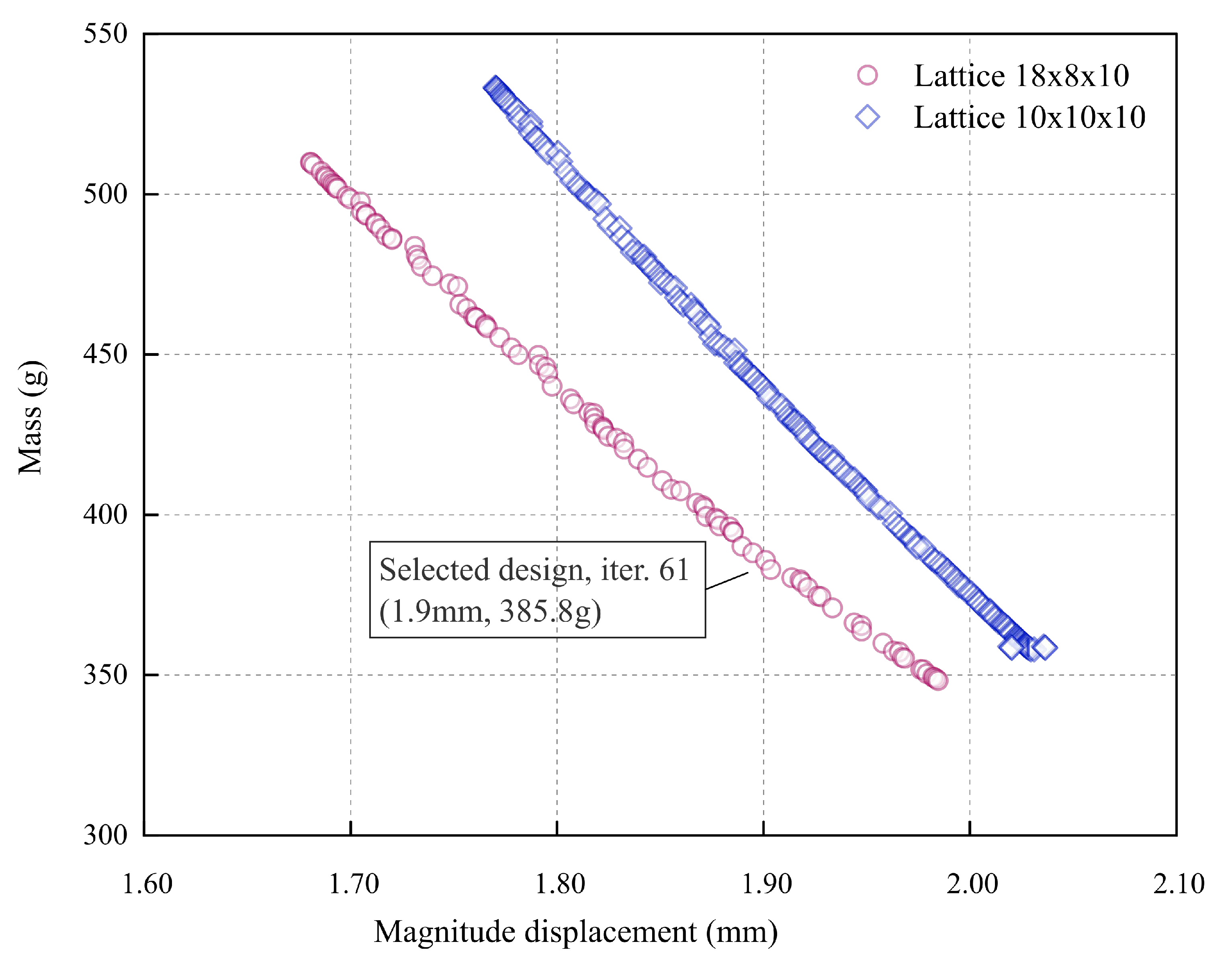
The output of the design exploration step is shown in
Figure 8. A Pareto plot shows the sets of optimum designs for the defined constraints and objectives. The figure compares the results obtained from the analysis of the two models analysed of the shell-lattice types. The two curves obtained are linear, with Pearson’s R coefficient being adequately -0.9986 and -0.9995 for 18x8x10 and 10x10x10 curves, and offset from each other. The curve for the 18x8x10 lattice is shifted to the left of the 10x10x10 lattice curve. The figure shows that the solution with lattice 18x8x10 performs better regarding the stiffness-to-mass ratio. The difference between both lattice types is significant and reduces with the mass decrease since both curves have a different slope. The curve slope of the 18x8x10 lattice is smaller than the second lattice. Looking at
Figure 8, it is apparent that there are many different possible solutions; however, the printability without internal support and the print resolution limits the possible design candidates.
The minimum mass of 348.3g was obtained for the constant thickness of the lattice of 0.5mm for the lattice 18x8x10mm with a maximum displacement of 1.985mm. Unfortunately, this solution is not the best for manufacturing reasons and print quality; as it has been explained, 0.5mm thickness is difficult to achieve for the infill during printing. Including the part oversizing due to the post-sintering shrinkage, the wall of 0.5mm needs to be printed as 0.6mm. The used nozzle size is 0.4mm, so it is impossible to achieve the required thickness. Therefore, choosing a structure with a marginally thicker minimum wall thickness will be more sensible, giving greater rigidity and making it easier to manufacture the arm. Thus, to prototype the arm, the authors choose the design that is marked in
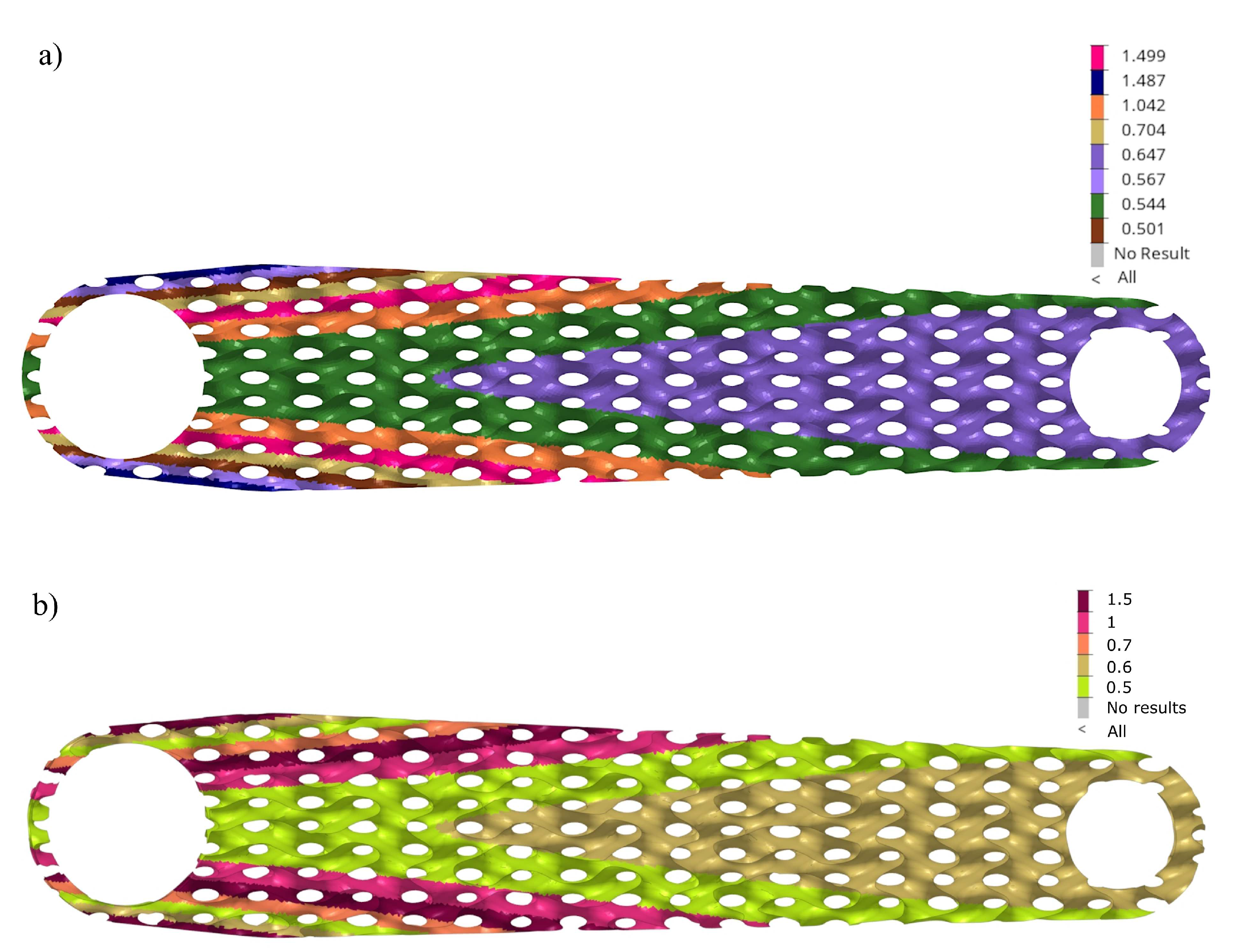
Figure 8–iteration 61. The selected design has a mass of 385.8g with a resulting displacement of 1.9mm. We showed the thickness distribution of the selected solution (iter. 61) in
Figure 9(a), and in this design candidate, the region of the critical thickness of 0.5mm is greatly reduced. Considering technological limitations, this distribution was slightly adjusted to the printing prototypes (
Figure 9(b)).
The general thickness distribution is not surprising—it follows approximately a bending stress map in a cantilever beam. However, a specific local perturbation in the distribution is unexpected around the large hole: a sudden decrease in thickness in the lattice’s outer layers and a renewed increase.
3.2. Optimum Solution
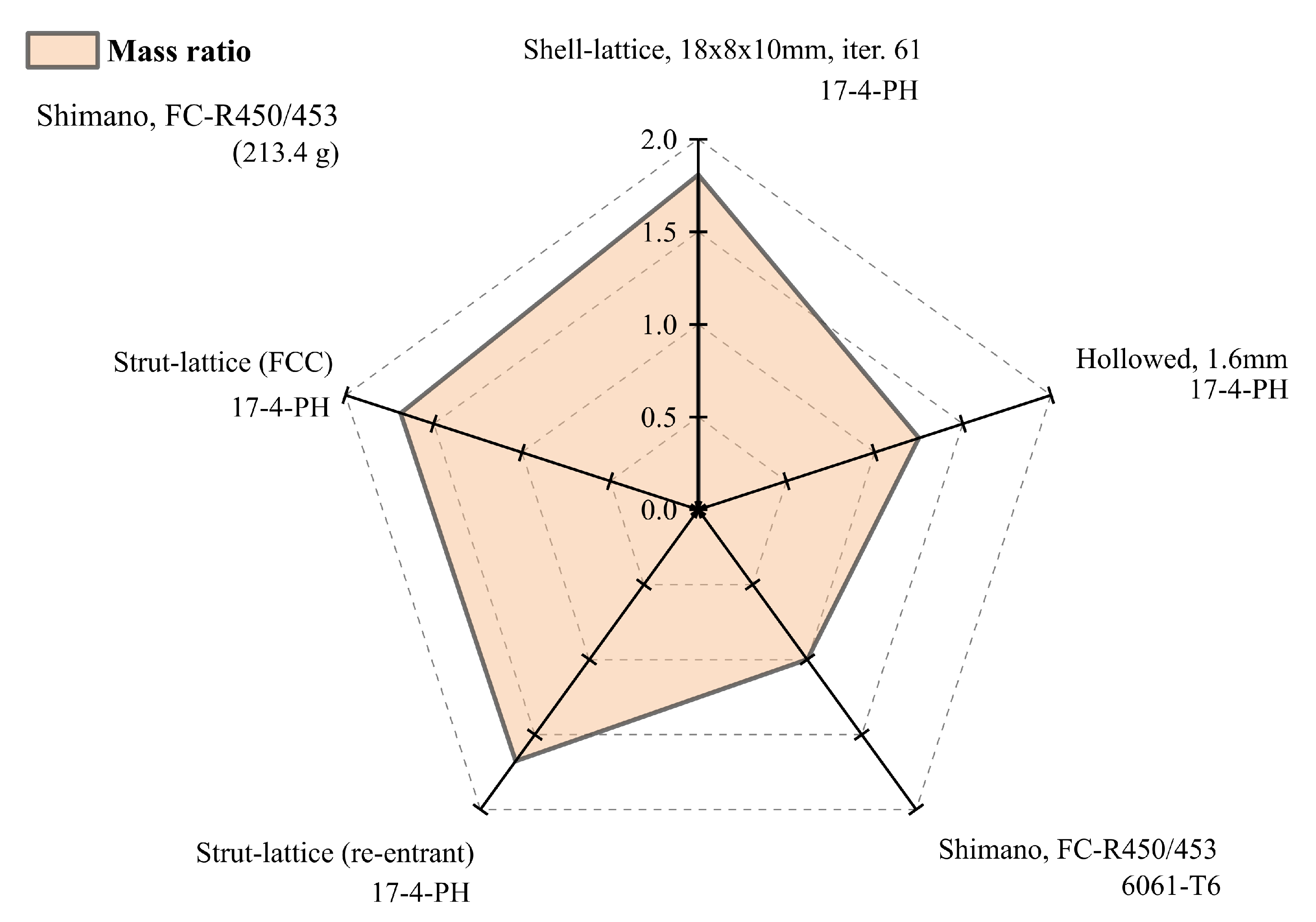
Comparing the mass of the analysed crank arms results in
Figure 10 and
Table 4, the chosen design with shell-lattice has 1.81 times greater mass than the reference design and slightly more than the crank arm with the strut-lattices having that ratio of 1.67. It should be remembered that the reference arm (Shimano FC-R450/543) is made of aluminium, and the others are made of stainless steel. Therefore the obtained ratio of 1.81 is a reasonably good result compared to the specific density ratio of 2.8 between steel and aluminium. The authors added the mass of the hollowed arm with a thickness of 1.6mm, having a ratio of 1.25. However, it must be remembered that the hollowed construction does not meet the criteria for maximum permissible stresses, with the maximum von Mises stress of 360MPa.
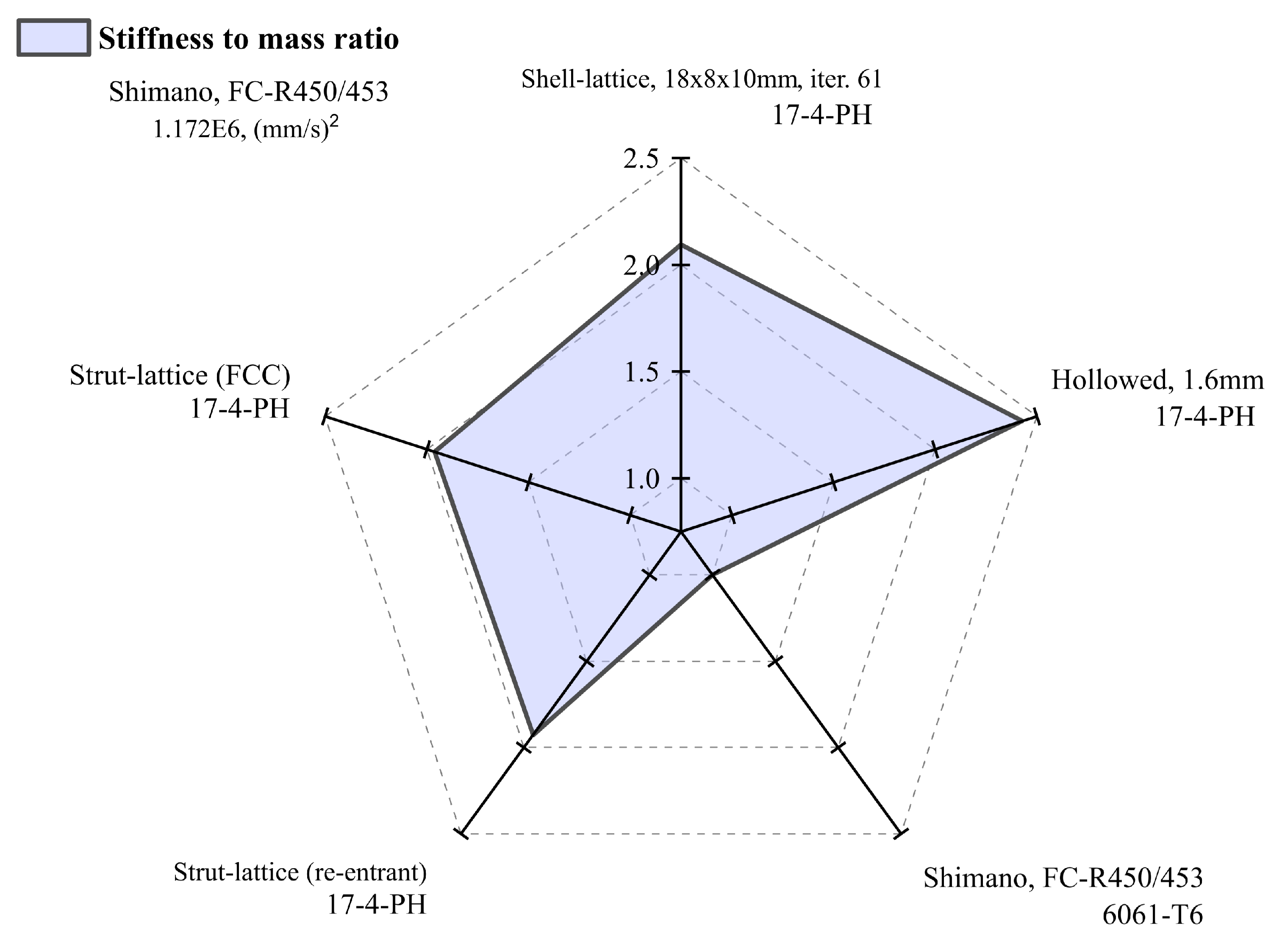
More exciting results are shown in
Figure 11 and
Table 4, where the stiffness-to-mass ratio is presented for the same structures. Here we see that the developed arm with the surface lattice is by far the best in this category. The ratio reaches a value of 2.10 compared to the design with the strut-lattices of 1.67, including the reference design of 1. The best solution for 2.43 is the hollow design, but it should be remembered that it is excluded due to unacceptable stress levels.
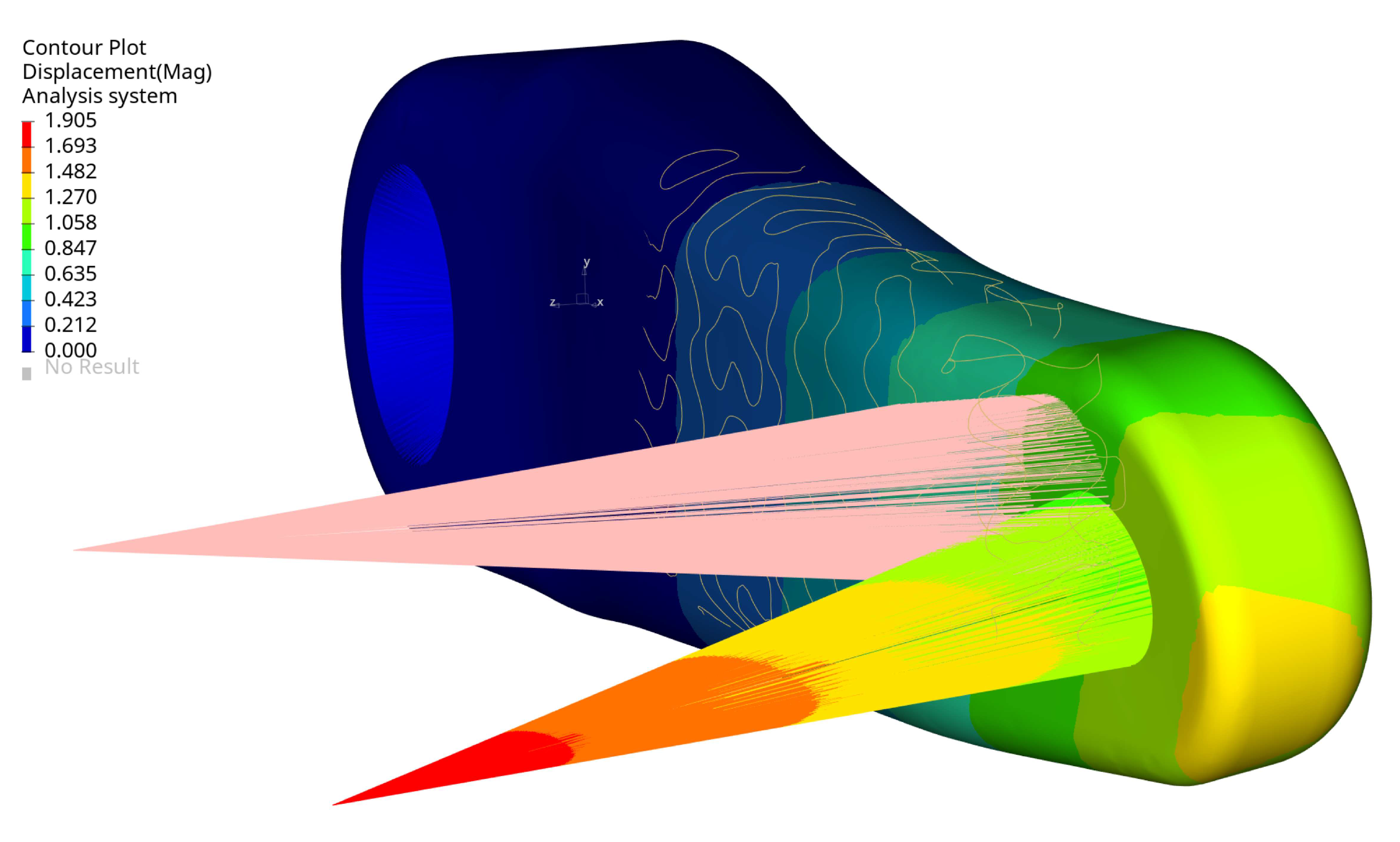
Figure 12 presents the magnitude displacement of the selected arm design under a defined load, as it can be seen that the load is dominated by bending in two planes and torsion. For the structural assessment, the maximum displacements of the node at the pedal centre (load application point) were considered.
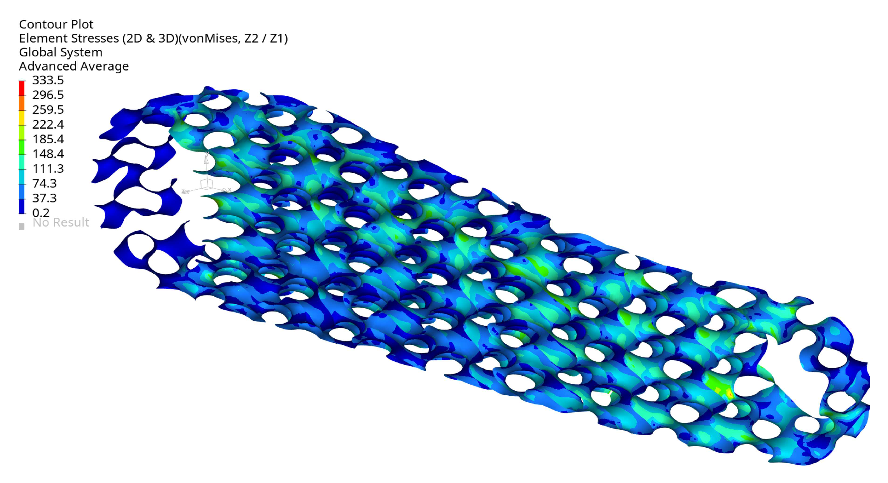
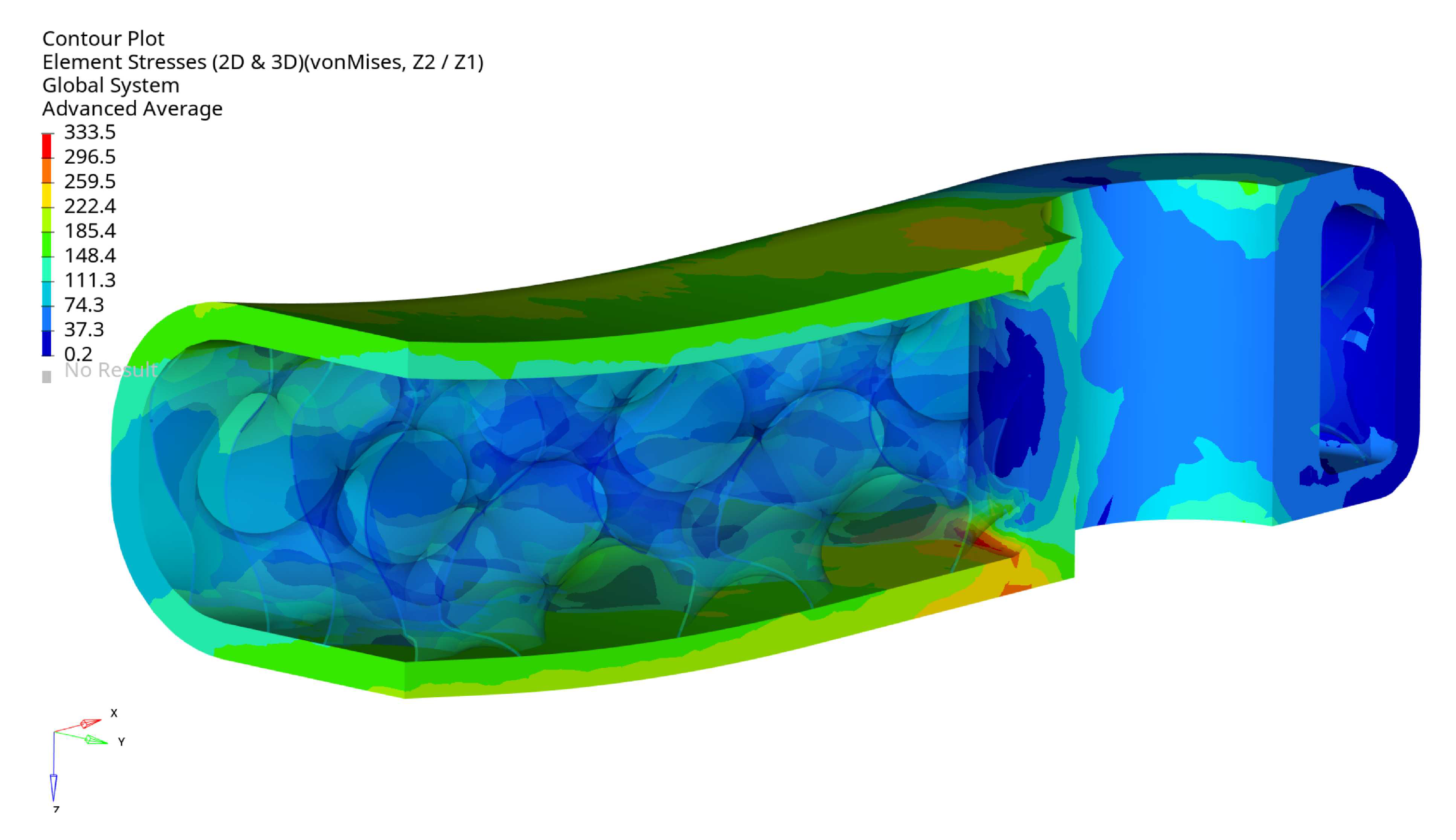
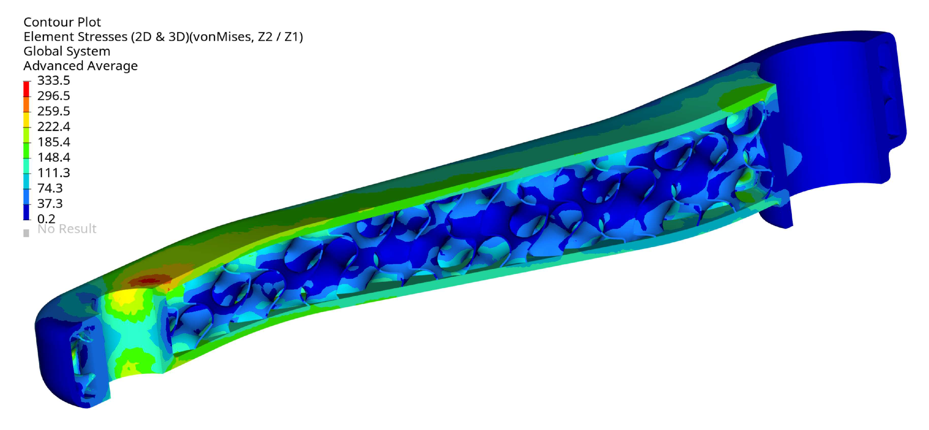
Figure 13 displays the von Mises stress in the crank arm’s internal shell lattice for the selected optimal configuration. As can be seen, the stress level is below the defined stress limit of 360MPa. The results are plotted from the shell elements’ external layers (top and bottom). The maximum stress is located around the small hole in the crank arm. There, the load is applied through the RBE3 element. The maximum stress position is not surprising; they should typically be expected around the fixation and the load location. This effect can also be seen in
Figure 14 and
Figure 15 on the arm’s external surface close to the hole used to assemble a pedal. That stress concentration shows the level of von Mises stresses below 333MPa.
Figure 13 shows that the maximum stress of 333.5MPa is in the arm’s shell part inside the cavity on the radius. The stress level is acceptable, but it is evident that local geometry modifications can reduce the stress in future investigations.
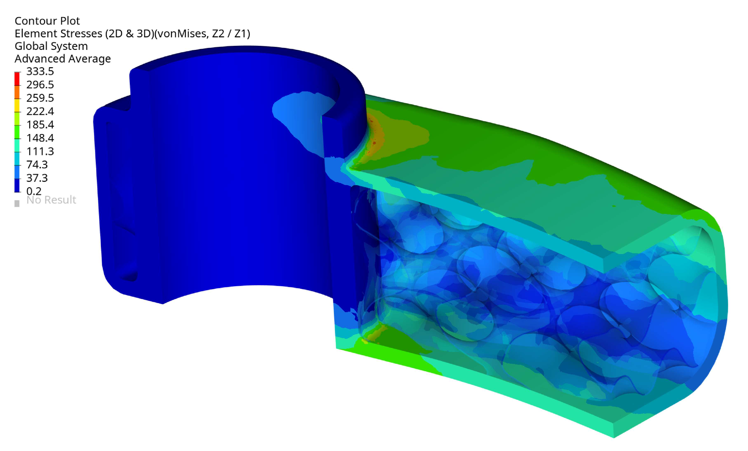
The arm’s fixation looks very well designed, the stress level is relatively low, and the design does not need to be modified. The stress level is below 333.5MPa, and the maximum is located in the radius of the external surface
Figure 16. The maximum stress localisation is fully explainable and expected due to how it is fixed and the load type. In reality, lower stresses are expected because the used boundary conditions are simplified, resulting in stiffening the places where the loads have been applied. That effect translates into higher stresses and is created directly by the RBE2 element (it adds locally infinite stiffness to a structure).
3.3. Prototype
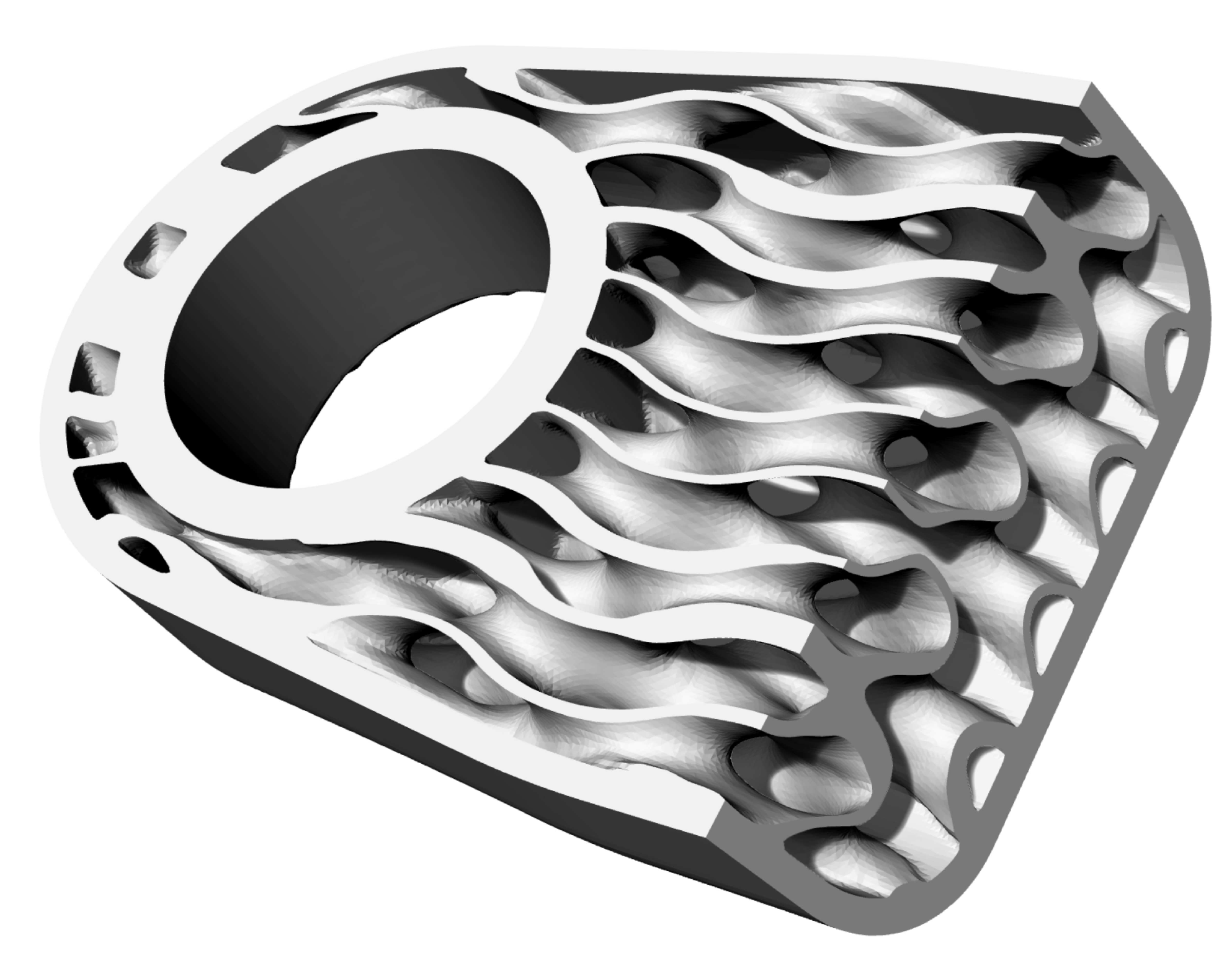
Complex geometry requires many elements to represent the print model properly; therefore, the size of the generated STL file (inter. 61) was huge, about 600MB. Finally, it was possible to handle the file without significant difficulties. A part of the generated STL model is shown in
Figure 17; it reflects the complex internal geometry of the developed infill.
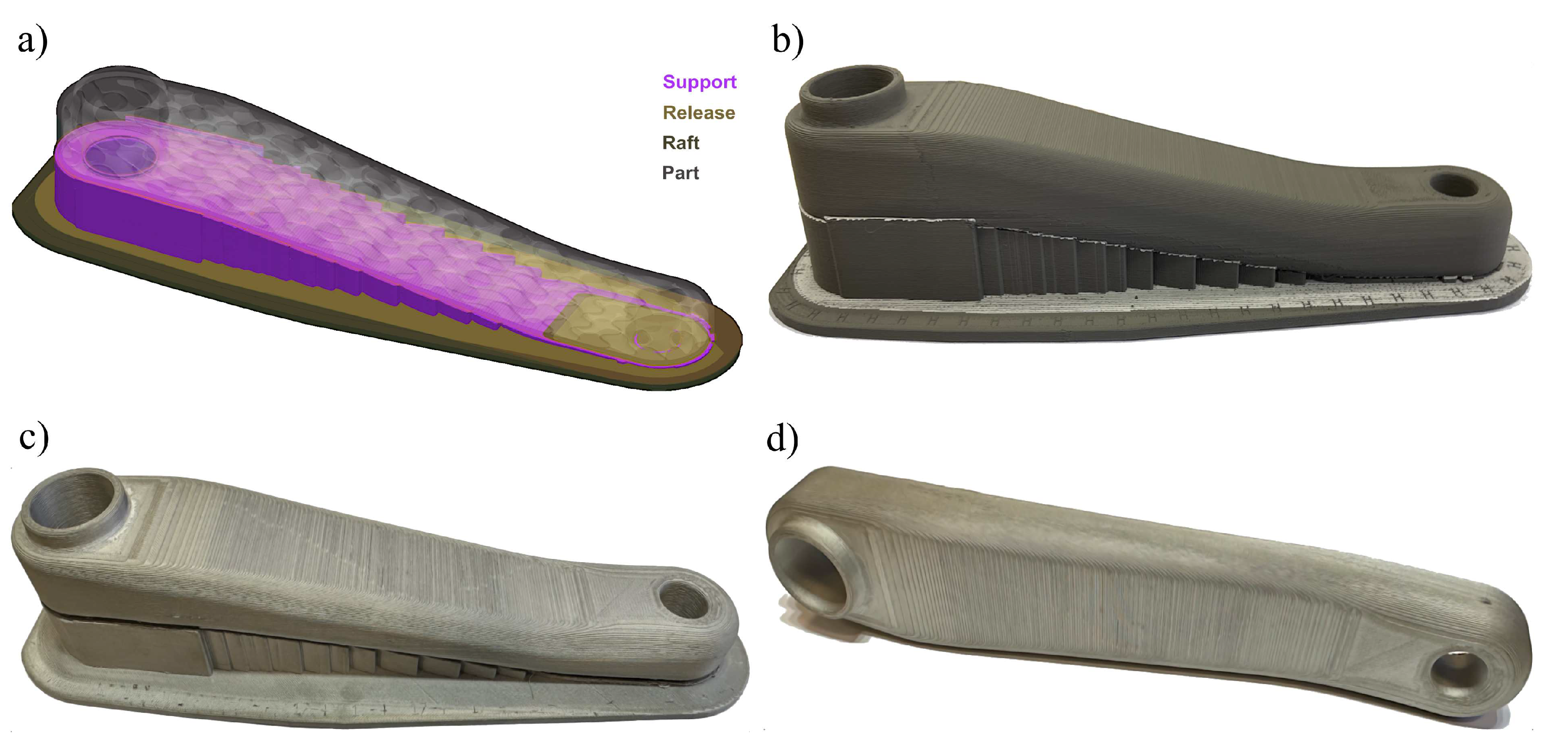
The sintered crank arm (
Figure 18d)) had a mass of 343.8g and no visible cracks on its external surfaces. The green part and the sintered one had a typical surface roughness determined by layer-by-layer material deposition of the metal FFF technology, as shown in
Figure 18. Interestingly, the measured mass of 343.8g of the crank arm represented only 89% of the 3D model’s mass of 385.8g, and an explanation of this will be provided later in the article.
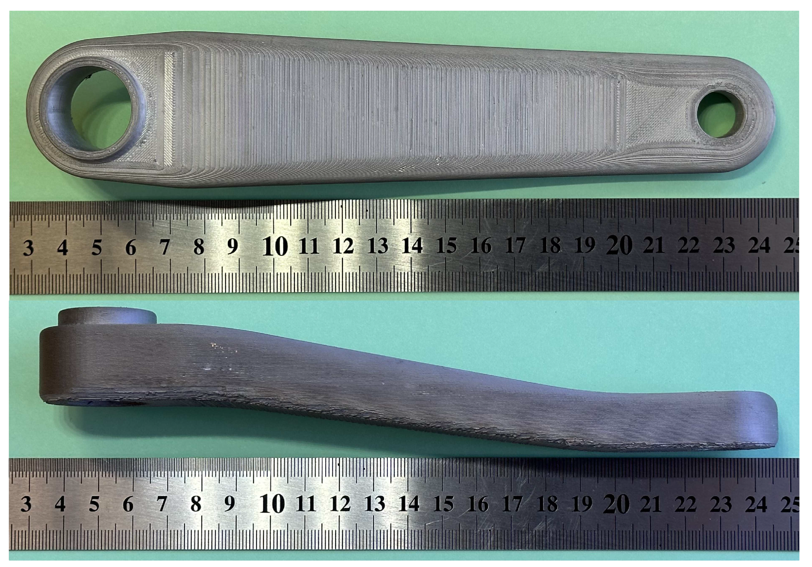
The printing and sintering process succeeded with the required external dimensions of the crank arm, as shown in
Figure 19. The external surface of the part has a typical metal FFF technology texture caused by the distribution of material layers while printing.
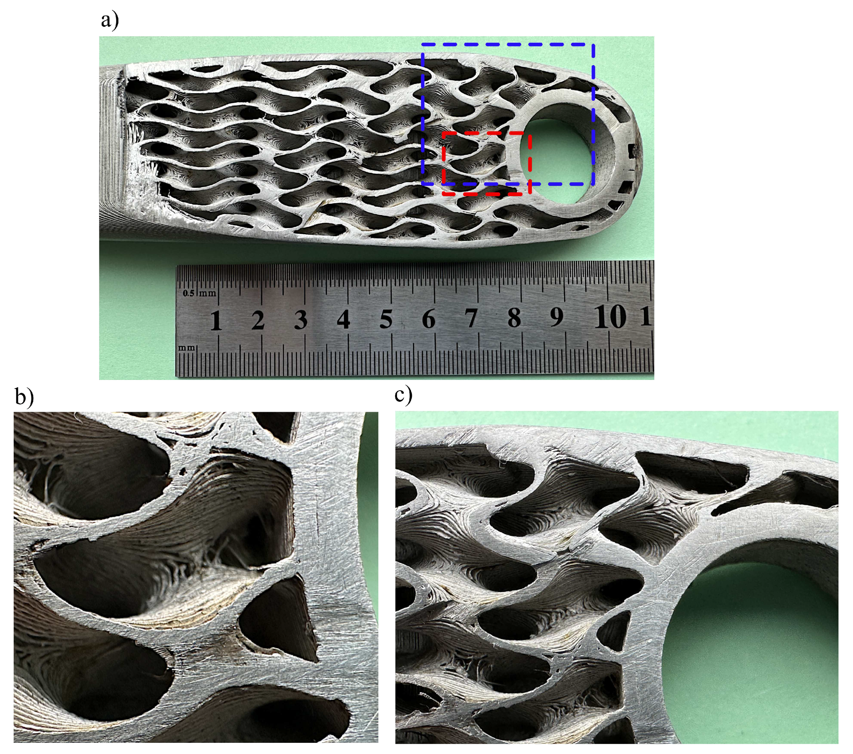
Also, the infill structures showed the same typical texture of metal FFF parts. However, the infill was not represented entirely correctly;
Figure 20(a)-(c) shows that unsintered and missing layers caused gaps in the infill, occurring randomly throughout its volume.
4. Discussion
It was hypothesised that the functionally graded internal shell lattice could be implemented in real mechanical parts and that application can benefit structural performance. The literature review shows that several works are devoted to specimens, not whole and geometrically complex parts. The presented work shows that it is feasible to design the functionally graded lattice as the infill in the crank arm using the metal FFF technology and existing tools. The original design and analysis method is proposed. In detail, the authors show how to efficiently represent the crank arm’s geometry with the functionally graded infill and how to search the design space for the optimum design. Finally, the optimum configuration was selected considering the manufacturing requirements from the sets of optimum designs for the defined constraints and objectives—Pareto plot in
Figure 8. The results show that a satisfactory outcome regarding the stiffness-to-mass ratio is possible. In the presented work, that ratio is much better than the existing reference design, see
Table 4, although the lattice cell was chosen to meet the manufacturing requirements (overhangs and visible lattice structure after sintering). Theoretically, there is room for improvement by selecting a more appropriate cell grid and thickness distribution. However, this requires developing a new sophisticated selection strategy that must include aspects of a chosen manufacturing method.
The authors believe the chosen stress limit of 360MPa for optimisation is appropriate for the given loads and considering the project’s objectives. The structural performance of the optimised crank arm was done based on the finite element method for the simplified model without the small fillets in the infill, which make the assessment more conservative. However, because of the exceptionally large strength variability caused by internal material defects shown in work [
16], there should be no illusion that metal FFF technology can currently be applied to functional parts. It is hoped that further development into improving the material strength of parts produced by the metal FFF printing process will enable their application. It is particularly important when applied to crank arms, as failures due to fatigue fractures of crank arms occur in bicycles [
56,
57]. It is crucial to ensure a safe design, as failure can result in serious injury to the cyclist.
The most important result of the work was the original elaborated method of the structure’s design with functionally graded lattice structures. The proposed method can adapt to any structure, boundary conditions, and manufacturing constraints. Design exploration and finite element analysis together can be excellent tools for that problem, as shown in the article. Unluckily, the procedure is required to assume a pattern of the lattice cell distribution; however, it enables us to consider the manufacturing constraints. Additionally, the initial distribution of the lattice thicknesses is recommended to reduce the number of design variables to speed up optimisation. A dream method would be a design exploration procedure containing a mechanism that gives a graded distribution of grid cells with variable thickness with no initial constraints. It is conceivable that a field defined by an equation, cloud points or a stress gradient could guide the grid cell size distribution and variable thickness and consider manufacturing constraints. The authors believe it is currently impossible or unnecessary to create such a method; that is confirmed because no one has shown such a working solution for a 3D complex part.
The following important outcome of the project is testing the limits of the metal FFF additive technology. Unexpectedly, the most complicated part of the project was additive manufacturing. Although printing technology opens up space to create complex structures, there are still areas where further development is necessary. The crank arm’s example with the complex infill shows the technical limitations of the technology. Here, we can start pointing out the obstacles. Firstly, slicing software cannot always cope with huge data sets. As shown in the project, the STL file format forced the handling of huge model files of hundreds of megabytes for complex geometry parts. Secondly, slicing software is often limiting in its ability to interfere with a support structure. For instance, it automatically generates a predefined support structure that needs to be manually modified, which can be very difficult for complex geometry. Thirdly, the metal FFF technology limits printing thin-walled infill structures by filament material properties and the nozzle size. An example can be seen in
Figure 20, where the defects are observed. Most likely, the faults were caused by the localised material collapse while printing due to the filament properties and insufficient support of the complex thin-walled infill. The last main obstacle is the maximum size of printed objects, often limited to 160x130x300mm for Markforged, Metal-X Sinter-2 oven. That constraint is caused mainly by sintering process capabilities. Manufacturing larger objects are feasible, but problems during the sintering process are expected. As shown in the paper, the printing time is also an issue because it can be very long for parts with thin-walled internal structures reaching dozens of hours.
As an example of the difficulties, it is noteworthy that it took the authors about a year to print the prototype shown in
Figure 19, and only the latest version of the slicer software Eiger.io [
58] and version 2 of 17–4 PH filament made it possible printing with shown quality in
Figure 20.
As was mentioned, we noticed a significant variation between the masses of the model and the actual printed and sintered parts by 11%. An existing porosity of the sintered part cannot explain its level. The maximum observed porosity in the metal FFF technology is 6.5% based on the review presented in [
16]. Therefore, additional factors must contribute to the mass difference. So, the discrepancy is caused by the inappropriate geometric representation of the internal lattice see
Figure 20. Thus, the shown manufacturing faults contribute to the observed difference. Unfortunately, a precise measurement of the infill geometry in the sintered part is unrealistic, so no proof of measurement results can be provided.
5. Conclusions
The findings based on the presented case study suggest that the functionally graded lattices based on shell structure significantly improve the structural performance of the mechanical components. Therefore the study strengthens the idea that functionally graded materials /structures can benefit by mimicking natural materials. This study shows that the existing technology software, analysis methods, and hardware are developed satisfactorily to support the design process. The evidence suggests that designing the structures with functionally graded lattices is feasible for complex parts, and an example of the methodology was shown. However, further development is needed in the metal FFF technology. Several limitations are recorded while implementing the functionally graded lattice in design for the metal FFF technology. The restrictions concern additive manufacturing and its technical limitations in software and hardware. The most critical constraints concerning 3D printing and sintering complex infill parts are the minimum thickness wall, the maximum part size and filament materials. More broadly, development is needed to improve three elements in the future.
Firstly, work is required to improve the metal FFF technology for printing thin-walled internal structures, with issues relating to nozzle size, printing parameters and printer control algorithms.;
Secondly, improvements are required in metallic filament materials for the metal FFF technology to enhance printability and reduction of post-sintered internal defects, thereby increasing the strength;
Thirdly, it is recommended to develop methods for generating field-controlled lattice structures and integration in CAD systems that enhance design optimisation and exploration, opening up space for new types of high-performance parts.
This work contributes to the existing knowledge of design for 3D printing by providing the developed design methodology. The study’s strength is the presentation of the in-depth design process of those structures and an identification of the boundaries of the metal FFF technology.
Author Contributions
Conceptualization, S.K. and T.D.; methodology, S.K. and T.D.; software, S.K.; validation, S.K., E.M. and T.d.; formal analysis, S.K.; investigation, S.K, E.M. and T.D.; resources, S.K.; data curation, S.K.; writing—original draft preparation, S.K.; writing—review and editing, S.K. and T.D.; visualization, S.K.; supervision, S.K.; project administration, S.K.; funding acquisition, S.K. All authors have read and agreed to the published version of the manuscript.
Funding
This research received no external funding
Conflicts of Interest
The authors declare no conflict of interest.
Abbreviations
The following abbreviations are used in this manuscript:
| AM |
Additive Manufacturing |
| CAD |
Computer-Aided Design |
| DE |
Design Exploration |
| DOE |
Design of Experiments |
| DSE |
Design Space Exploration |
| FCC |
Face-Centred Cubic |
| FDM |
Fused Deposition Modelling |
| FEA |
Finite Element Analysis |
| FFF |
Fused Filament Fabrication |
| FGM |
Functionally Graded Materials |
| FGS |
Functionally Graded Structures |
| GRSM |
Global Response Search Method |
| ISO |
International Organization for Standardization |
| MELS |
Modified Extensible Lattice Sequences |
| MEX |
Metal Extrusion Method |
| MOO |
Multiobjective Optimisation |
| nTop |
nTopology |
| PBF |
Powder Bed Fusion |
| SLS |
Selective Laser Sintering |
| TPMS |
Triply Periodic Minimal Surface |
References
- Munsch, M.; Schmidt-Lehr, M.; Wycisk, E. Binder jetting and FDM: a comparison with laser powder bed fusion and metal injection moulding. https://www.metal-am.com/articles/binder-jetting-fdm-comparison-with-powder-bed-fusion-3d-printing-injection-moulding/, accessed on 2022-10-15.
- Podroužek, J.; Marcon, M.; Ninčević, K.; Wan-Wendner, R. Bio-inspired 3D infill patterns for additive manufacturing and structural applications. Materials 2019, 12, 1–13. [Google Scholar] [CrossRef] [PubMed]
- Abate, K.M.; Nazir, A.; Yeh, Y.P.; Chen, J.E.; Jeng, J.Y. Design, optimization, and validation of mechanical properties of different cellular structures for biomedical application. International Journal of Advanced Manufacturing Technology 2020, 106, 1253–1265. [Google Scholar] [CrossRef]
- Afshar, M.; Anaraki, A.P.; Montazerian, H.; Kadkhodapour, J. Additive manufacturing and mechanical characterization of graded porosity scaffolds designed based on triply periodic minimal surface architectures. Journal of the Mechanical Behavior of Biomedical Materials 2016, 62, 481–494. [Google Scholar] [CrossRef]
- Jia, H.; Lei, H.; Wang, P.; Meng, J.; Li, C.; Zhou, H.; Zhang, X.; Fang, D. An experimental and numerical investigation of compressive response of designed Schwarz Primitive triply periodic minimal surface with non-uniform shell thickness. Extreme Mechanics Letters 2020, 37, 100671–100671. [Google Scholar] [CrossRef]
- Lee, D.W.; Khan, K.A.; Abu Al-Rub, R.K. Stiffness and yield strength of architectured foams based on the Schwarz Primitive triply periodic minimal surface. International Journal of Plasticity 2017, 95, 1–20. [Google Scholar] [CrossRef]
- Li, Y.; Feng, Z.; Hao, L.; Huang, L.; Xin, C.; Wang, Y.; Bilotti, E.; Essa, K.; Zhang, H.; Li, Z.; Yan, F.; Peijs, T. A Review on functionally graded materials and structures via additive manufacturing: from multi-scale design to versatile functional properties. Advanced Materials Technologies 2020, 5. [Google Scholar] [CrossRef]
- Maskery, I.; Hussey, A.; Panesar, A.; Aremu, A.; Tuck, C.; Ashcroft, I.; Hague, R. An investigation into reinforced and functionally graded lattice structures. Journal of Cellular Plastics 2017, 53, 151–165. [Google Scholar] [CrossRef]
- Yang, L.; Yan, C.; Cao, W.; Liu, Z.; Song, B.; Wen, S.; Zhang, C.; Shi, Y.; Yang, S. Compression–compression fatigue behaviour of gyroid-type triply periodic minimal surface porous structures fabricated by selective laser melting. Acta Materialia 2019, 181, 49–66. [Google Scholar] [CrossRef]
- Czerwinski, F. Current Trends in Automotive Lightweighting Strategies and Materials. Materials 2021, 14, 6631. [Google Scholar] [CrossRef]
- Oczoś, Kazimierz, E. Konstrukcje lekkie–istota, rodzaje, realizacja i zastosowanie. Cz. 1. Mechanik 2011, 84, 271–272. [Google Scholar]
- Oczoś, Kazimierz, E. Konstrukcje lekkie–istota, rodzaje, realizacja i zastosowanie. Cz. 2. Mechanik 2011, 84, 377–390. [Google Scholar]
- Oftadeh, R.; Perez-Viloria, M.; Villa-Camacho, J.C.; Vaziri, A.; Nazarian, A. Biomechanics and mechanobiology of trabecular bone: a review. Journal of Biomechanical Engineering 2015, 137, 1–15. [Google Scholar] [CrossRef] [PubMed]
- Sato, M.; Inoue, A.; Shima, H. Bamboo-inspired optimal design for functionally graded hollow cylinders. PLoS ONE 2017, 12, 1–14. [Google Scholar] [CrossRef] [PubMed]
- Spencer, O.O.; Yusuf, O.T.; Tofade, T.C. Additive manufacturing technology development: a trajectory towards industrial revolution. American Journal of Mechanical and Industrial Engineering 2018, 3, 80–90. [Google Scholar] [CrossRef]
- Kedziora, S.; Decker, T.; Museyibov, E.; Morbach, J.; Hohmann, S.; Huwer, A.; Wahl, M. Strength properties of 316L and 17-4 PH stainless steel produced with additive manufacturing. Materials 2022, 15, 6278. [Google Scholar] [CrossRef] [PubMed]
- Koizumi, M. FGM activities in Japan. Composites Part B: Engineering 1997, 28, 1–4. [Google Scholar] [CrossRef]
- Saleh, B.; Jiang, J.; Fathi, R.; Al-hababi, T.; Xu, Q.; Wang, L.; Song, D.; Ma, A. 30 Years of functionally graded materials: An overview of manufacturing methods, Applications and Future Challenges. Composites Part B: Engineering 2020, 201, 108376. [Google Scholar] [CrossRef]
- Mahmoud, D.; Elbestawi, M. Lattice structures and functionally graded materials applications in additive manufacturing of orthopedic implants: a review. Journal of Manufacturing and Materials Processing 2017, 1, 13–13. [Google Scholar] [CrossRef]
- Kou, X.Y.; Parks, G.T.; Tan, S.T. Optimal design of functionally graded materials using a procedural model and particle swarm optimization. CAD Computer Aided Design 2012, 44, 300–310. [Google Scholar] [CrossRef]
- Miyamato, Y.; Kaysser, W.; Rabin, B.; Kawasaki, A.; Ford, R. Functionally Graded Materials: Design, Processing and Application; Vol. 1, Springer Science and Business Media, Springer Science and Business Media, 2013; pp. 1–339. [CrossRef]
- Wu, J.; Aage, N.; Westermann, R.; Sigmund, O. Infill optimization for additive manufacturing-approaching bone-like porous structures. IEEE Transactions on Visualization and Computer Graphics 2018, 24, 1127–1140. [Google Scholar] [CrossRef]
- Gries, M. Methods for evaluating and covering the design space during early design development. Integration, the VLSI Journal 2004, 38, 131–183. [Google Scholar] [CrossRef]
- Kang, E.; Jackson, E.; Schulte, W. An approach for effective design space exploration, 2011. [CrossRef]
- Pan, C.; Han, Y.; Lu, J. Design and optimization of lattice structures: a review. Applied Sciences 2020, 10, 6374–6374. [Google Scholar] [CrossRef]
- Al-Saedi, D.S.; Masood, S.H.; Faizan-Ur-Rab, M.; Alomarah, A.; Ponnusamy, P. Mechanical properties and energy absorption capability of functionally graded F2BCC lattice fabricated by SLM. Materials and Design 2018, 144, 32–44. [Google Scholar] [CrossRef]
- Zheng, X.; Lee, H.; Weisgraber, T.H.; Shusteff, M.; DeOtte, J.; Duoss, E.B.; Kuntz, J.D.; Biener, M.M.; Ge, Q.; Jackson, J.A.; Kucheyev, S.O.; Fang, N.X.; Spadaccini, C.M. Ultralight, ultrastiff mechanical metamaterials. Science 2014, 344, 1373–1377. [Google Scholar] [CrossRef] [PubMed]
- Ashby, M.F. The properties of foams and lattices. Philosophical Transactions of the Royal Society A: Mathematical, Physical and Engineering Sciences 2006, 364, 15–30. [Google Scholar] [CrossRef] [PubMed]
- Deshpande, V.S.; Fleck, N.A.; Ashby, M.F. Effective properties of the octet-truss lattice material. Journal of the Mechanics and Physics of Solids 2001, 49, 1747–1769. [Google Scholar] [CrossRef]
- Decker, T.; Kedziora, S.; Wolf, C. Practical implementation of functionally graded lattice structures in a bicycle crank arm, 2020.
- Schoen, A.H. Infinite periodic minimal surfaces without self-intersections. Report, NASA, 1970.
- Abueidda, D.W.; Elhebeary, M.; Shiang, C.S.; Pang, S.; Abu Al-Rub, R.K.; Jasiuk, I.M. Mechanical properties of 3D printed polymeric Gyroid cellular structures: Experimental and finite element study. Materials and Design 2019, 165, 107597. [Google Scholar] [CrossRef]
- Bean, P.; Lopez-Anido, R.A.; Vel, S. Numerical modeling and experimental investigation of effective elastic properties of the 3D printed gyroid infill. Applied Sciences 2022, 12. [Google Scholar] [CrossRef]
- Silva, C.; Pais, A.I.; Caldas, G.; Gouveia, B.P.P.A.; Alves, J.L.; Belinha, J. Study on 3D printing of gyroid-based structures for superior structural behaviour. Progress in Additive Manufacturing 2021, 6, 689–703. [Google Scholar] [CrossRef]
- Al-Ketan, O.; Abu Al-Rub, R.K. MSLattice: A free software for generating uniform and graded lattices based on triply periodic minimal surfaces. Material Design and Processing Communications 2020, 3, e205. [Google Scholar] [CrossRef]
- Zhang, X.Y.; Yan, X.C.; Fang, G.; Liu, M. Biomechanical influence of structural variation strategies on functionally graded scaffolds constructed with triply periodic minimal surface. Additive Manufacturing 2020, 32, 101015. [Google Scholar] [CrossRef]
- Han, C.; Li, Y.; Wang, Q.; Wen, S.; Wei, Q.; Yan, C.; Hao, L.; Liu, J.; Shi, Y. Continuous functionally graded porous titanium scaffolds manufactured by selective laser melting for bone implants. Journal of the mechanical behavior of biomedical materials 2018, 80, 119–127. [Google Scholar] [CrossRef]
- Quaresimin, M.; Meneghetti, G.; Verardo, F. Design and optimisation of an RTM composite bicycle crank. Journal of Reinforced Plastics and Composites 2001, 20, 129–146. [Google Scholar] [CrossRef]
- McEwen, I.; Cooper, D.E.; Warnett, J.; Kourra, N.; Williams, M.A.; Gibbons, G.J. Design and manufacture of a high-performance bicycle crank by additive manufacturing. Applied Sciences 2018, 8. [Google Scholar] [CrossRef]
- Gutiérrez-Moizant, R.; Ramírez-Berasategui, M.; Calvo, J.A.; Álvarez Caldas, C. Validation and improvement of a bicycle crank arm based in numerical simulation and uncertainty quantification. Sensors 2020, 20, 1814. [Google Scholar] [CrossRef] [PubMed]
- Chang, R.R.; Dai, W.J.; Wu, F.Y.; Jia, S.Y.; Tan, H.M. Design and manufacturing of a laminated composite bicycle crank. Procedia Engineering 2013, 67, 497–505. [Google Scholar] [CrossRef]
- nTopology, T. nTopology, version 3.45.4. https://ntopology.com/ntop-platform, accessed on 2023-04-04.
- ISO. ISO 4210-8:2023 Cycles - Safety requirements for bicycles - Part 8: Pedal and drive system test methods, 2023.
- Whitt, F.R.; Wilson, D.G. Bicycling science, 2 ed.; MIT Press: Cambridge, Mass, 1982; p. 364. [Google Scholar]
- Markforged, T. Metal-X System. https://markforged.com/metal-x/, accessed on 2022-03-15.
- BASF, T. Ultrafuse FFF. https://www.ultrafusefff.com/product-category/metal/ultrafuse-316l/, accessed on 2021-02-14.
- Foundry, T.V. Manufacturing metal 3d printing filaments and materials. https://www.thevirtualfoundry.com/, accessed on 2022-09-12.
- Team, T.D.M. Studio System™ 2. https://www.desktopmetal.com/products/studio, accessed on 2022-05-12.
- Engineering, A. Altair HyperStudy Guide, 2022.1. https://altairhyperworks.com/product/HyperStudy, accessed on 2023-02-03.
- Engineering, T.A. OptiStruct, Version 2022.1. https://www.altair.com/optistruct/, accessed on 2023-02-08.
- Jaimes, A.L.; Martínez, S.Z.; Coello, C.A.C., An introduction to multiobjective optimization techniques. In Optimization in Polymer Processing; Gaspar-Cunha, A.; Covas, J., Eds.; Chemical engineering methods and technology, Nova Science Publishers, 2011; pp. 29–57.
- Engineering, A. Altair HyperStudy Guide, version 2022.1, DOE Modified extensible lattice sequence. https://2022.help.altair.com/2022.1/hwdesktop/hst/topics/design_exploration/method_modified_extensible_lattice_sequence_doe_r.htm, accessed on 2023-04-03.
- Ollar, J. A multidisciplinary design optimisation framework for structural problems with disparate variable dependence. Thesis, Queen Mary University of London, 2016.
- Markforged, T. 17-4 PH stainless steel. https://static.markforged.com/downloads/17-4-ph-stainless-steel.pdf, accessed on 2022-11-09.
- Bjørheim, F.; Lopez, I.L.T. Tension testing of additively manufactured specimens of 17-4 PH processed by Bound Metal Deposition, 2021. [CrossRef]
- Morgan, J.E.; Wagg, D.J. The failure of bike cranks, International Standards, tests and interpretations. Sports Engineering 2002, 5, 113–119. [Google Scholar] [CrossRef]
- Engineering, M. Component failure museum/ Bicycle crank failure II. http://technology.open.ac.uk/materials/mem/mem_ccf4.htm, accessed on 2022-07-15.
- Markforged, T. Eiger.io, Slicer 3.97.0. https://www.eiger.io/, accessed on 2023-01-09.
Figure 1.
CAD model of crank arm created based on Shimano FC-R450/453 crank arm.
Figure 1.
CAD model of crank arm created based on Shimano FC-R450/453 crank arm.
Figure 2.
Flowchart of design method of the crank arm with the graded lattice infill.
Figure 2.
Flowchart of design method of the crank arm with the graded lattice infill.
Figure 3.
Load configurations defined by the standard[
43].
Figure 3.
Load configurations defined by the standard[
43].
Figure 4.
Internal shell-lattice as gyroid surface: (a) 10x10x10mm lattice (X, Y, Z), (b) 18x8x10mm lattice.
Figure 4.
Internal shell-lattice as gyroid surface: (a) 10x10x10mm lattice (X, Y, Z), (b) 18x8x10mm lattice.
Figure 5.
Initial 2D distribution of thickness of shell-lattice, design variables based on Equation
2 and then discretised in 8 groups.
Figure 5.
Initial 2D distribution of thickness of shell-lattice, design variables based on Equation
2 and then discretised in 8 groups.
Figure 6.
Analysed FE models with 10x10x10mm (X, Y, Z) shell-lattice, view of solid and shell elements.
Figure 6.
Analysed FE models with 10x10x10mm (X, Y, Z) shell-lattice, view of solid and shell elements.
Figure 7.
Load and boundary conditions.
Figure 7.
Load and boundary conditions.
Figure 8.
Pareto-optimal set of solutions.
Figure 8.
Pareto-optimal set of solutions.
Figure 9.
Thickness distribution of shell-lattice of infill: (a) thickness of selected optimum design iter. 61, (b) thickness defined for printed prototypes.
Figure 9.
Thickness distribution of shell-lattice of infill: (a) thickness of selected optimum design iter. 61, (b) thickness defined for printed prototypes.
Figure 10.
Mass comparison between designs.
Figure 10.
Mass comparison between designs.
Figure 11.
Stiffness to mass ratio comparison between designs.
Figure 11.
Stiffness to mass ratio comparison between designs.
Figure 12.
Magnitude displacements (mm) selected optimal design, iter. 61.
Figure 12.
Magnitude displacements (mm) selected optimal design, iter. 61.
Figure 13.
Maximum von Mises stress (MPa) for selected optimal design at maximum load, view 1, iter. 61.
Figure 13.
Maximum von Mises stress (MPa) for selected optimal design at maximum load, view 1, iter. 61.
Figure 14.
Maximum von Mises stress (MPa) for selected optimal design at maximum load, view 2, iter. 61.
Figure 14.
Maximum von Mises stress (MPa) for selected optimal design at maximum load, view 2, iter. 61.
Figure 15.
Maximum von Mises stress (MPa) for selected optimal design at maximum load, view 3, iter 61.
Figure 15.
Maximum von Mises stress (MPa) for selected optimal design at maximum load, view 3, iter 61.
Figure 16.
Maximum von Mises stress (MPa) for selected optimal design at maximum load, view 4, iter. 61.
Figure 16.
Maximum von Mises stress (MPa) for selected optimal design at maximum load, view 4, iter. 61.
Figure 17.
Internal structures of STL model, iter. 61 (part of the whole model).
Figure 17.
Internal structures of STL model, iter. 61 (part of the whole model).
Figure 18.
Prototype of the crank arm, iter. 61: (a) model with support and raft structures. (b) green part, (c) sintered part with support structure, (d) sintered part.
Figure 18.
Prototype of the crank arm, iter. 61: (a) model with support and raft structures. (b) green part, (c) sintered part with support structure, (d) sintered part.
Figure 19.
Views of the printed and sintered crank arm (iter. 61).
Figure 19.
Views of the printed and sintered crank arm (iter. 61).
Figure 20.
Views of the sintered cut crank arm (iter. 61) showing the internal structure: (a) whole crank arm; (b) view of the infill marked by red rectangular, (c) view of the infill marked by blue rectangular.
Figure 20.
Views of the sintered cut crank arm (iter. 61) showing the internal structure: (a) whole crank arm; (b) view of the infill marked by red rectangular, (c) view of the infill marked by blue rectangular.
Table 1.
Printing settings for the Markforged 17–4 PH (version 2) filament.
Table 1.
Printing settings for the Markforged 17–4 PH (version 2) filament.
| Printing Parameters |
Value |
| Nozzle size, mm |
0.4 |
| Layer height, mm |
0.125 |
| Print bed temperature, °C |
115 |
| Metal hotend temperature, °C |
220 |
| Chamber temperature, °C |
48 |
| Oversizing factors: X, Y, Z, % |
19,5, 19.5, 20 |
Table 2.
Material properties as indicated by literature for 17–4 PH as sintered.
Table 2.
Material properties as indicated by literature for 17–4 PH as sintered.
| Parameters |
[16] |
[54] |
[55] |
| Print direction |
ZX (Upright) |
XY (Flat) |
XZ (On Edge) |
| Young’s modulus, GPa |
142 |
140 |
189 |
| Poisson’ ratio |
- |
0.272 |
- |
| Tensile strength, MPa |
496 |
1050 |
815 |
| Yield strength, MPa |
441 |
800 |
650 |
| Elongation at break, % |
0.4 |
5 |
0.86 |
| Density, g/cm3
|
- |
7.44 |
- |
| Hardness |
261HB |
30HRC |
- |
Table 3.
Material properties used in the analysis.
Table 3.
Material properties used in the analysis.
| Parameters |
Stainless steel 17–4 PH (as-sintered) |
Aluminium 6061–T6 |
| Young’s modulus, GPa |
170 |
69 |
| Poisson’ ratio |
0.27 |
0.33 |
| Stress limit, MPa |
360 |
- |
| Density, g/cm3
|
7.44 |
2.7 |
Table 4.
Results of analysed designs.
Table 4.
Results of analysed designs.
| Design |
Material |
Mass |
Displacement, mm |
Stiffness, N/mm |
Stiffness to Mass,
|
| Shimano FC-R450/453 |
6061–T6 |
213.4 |
7.20 |
250.2 |
1.172 |
| Strut-lattice (re-entrant) |
17-4 PH |
357.0 |
2.61 |
689.7 |
1.927 |
| Strut-lattice (FCC) |
17-4 PH |
360.0 |
2.55 |
705.9 |
1.961 |
| 18x8x10mm (Iter. 61) |
17-4 PH |
385.8 * |
1.90 |
947.4 |
2.456 |
| Hollowed, 1.6mm |
17-4 PH |
267.3 |
2.37 |
760.5 |
2.845 |
|
Disclaimer/Publisher’s Note: The statements, opinions and data contained in all publications are solely those of the individual author(s) and contributor(s) and not of MDPI and/or the editor(s). MDPI and/or the editor(s) disclaim responsibility for any injury to people or property resulting from any ideas, methods, instructions or products referred to in the content. |
© 2023 by the authors. Licensee MDPI, Basel, Switzerland. This article is an open access article distributed under the terms and conditions of the Creative Commons Attribution (CC BY) license (http://creativecommons.org/licenses/by/4.0/).
