1. Introduction
The reduction of building’s energy consumption has always been on the EU agenda as a flagship topic, bringing together both the research community and the industry, which have joined efforts in reducing energy dependency as a way to decrease resource consumption (water, energy, raw materials) to more environmentally friendly levels [
1]. One of the highest energy-consuming sectors is housing, which consumes close to 30% of the world’s total energy production according to the International Energy Agency (IEA) [
2,
3,
4]. This energy consumption is also reflected in the large amount of carbon dioxide emissions [
5,
6]. Building fabric, namely external envelope, as the case of facades play a relevant role in reducing energy demand of buildings performing two essential requirements: first, they are the barriers that separate the building's interior from the external environment, providing a liveable space for its inhabitants; and second, the aesthetical component and image of the building, responsible for its desirability.
High-performance sustainable facades can be defined as exterior enclosures that use the least possible amount of energy to maintain a comfortable indoor environment, which promotes a healthy and productive environment for the building's occupants. This means that sustainable facades are not simply barriers between interior and exterior, but rather building systems that can control or create a response to the external environment stimulus and significantly reduce buildings' energy consumption. One of the most fundamental parameters for the assessment of the energy efficiency of buildings components and solutions is the thermal transmittance (U-value). The definition of thermal transmittance, also known as the heat transfer coefficient or U-value (W/(m
2.K)), is the heat flow rate divided by the wall area and by the difference temperature between its two sides, in a steady-state [
7,
8].
One of the ways of better regulating indoor temperature in a passive manner is through the use of thermal energy storage (TES) materials, such as phase change materials (PCM). These materials are unique because they have high latent heat, making them very efficient at storing energy [
9], which can help stabilize indoor temperatures as to have lower temperature swing during the daily cycle.
In recent years, several research works on the incorporation of PCM in opaque building solutions, radiant floors, and glazing has been done using different encapsulation techniques and methods. The most commonly used type of PCM encapsulation is micro and macro encapsulation, and for the latter type of encapsulation there are different forms and shaped [
10,
11,
12,
13]. Another relevant factor for the correct use of PCM in building facades are the melting/solidification temperatures, positioning, latent heat capacity and average weather climate conditions [
14,
15,
16,
17].
Sovetova et al. [
15] presented a numerical analysis to evaluate the impact of the use of a microencapsulated PCM layer right between the outer layer (cement plaster and ceramic tile) and the concrete layer on the façade of a building in the hot desert region. They concluded that the reduction in energy consumption (ECR) could reach 34.26% and an economic analysis showed that the investment was feasible. In other studies [
16,
17], an aluminium tubular system with macroencapsulated PCM was developed and integrated into a wall. The authors concluded that there was a reduction in the thermal amplitude of all walls and roof ranging from 40.67% to 59.79%, responsible for a reduction of about 7% to 9% in the internal temperature of the room, as well as a reduction in the ambient thermal load of about 38% [
17]. Furthermore, still regarding the same solution mentioned above, [
16] managed to reduce the indoor peak temperature ranging from 0.2 ºC to 4.3 ºC and a reduction in indoor thermal amplitude ranging from -2.43% to 51.3%.
Bahrar et al [
18] performed a multiscale experimental characterization textile reinforced concrete panels with microencapsulated PCM, using the hot box method, as well as the development of a numerical model to accurately reproduce the thermal performance of the building envelope. The authors concluded that the higher the amount of PCM particles, the lower the thermal conductivity of the studied specimens is. Moreover, experiments undergone through real weather conditions demonstrated a reduction in peak internal surface temperature of up to 1.7 ºC.
Li et al.[
19] proceeded to assess a thermos-economic and environmental analysis of PCM embedded walls in rural residence of Northeast China, recurring to EnergyPlus
TM. Relatively to the PCM, the studied parameters were PCM layer position, PCM wall orientation and PCM melting point. Results showed an energy saving of 12.9% by a PCM filled wall near the interior surface. In comparison to the baseline case, the PCM filled wall in the south facade decreased the heating load by 12.8%. The optimum PCM melting temperature found to be 16 ºC for an interior temperature of 18 ºC and the carbon footprints were reduced by 52.7 kg/m
2 when utilizing the appropriate PCM wall throughout its lifecycle.
In a former study, Li et al [
20] explored both the thermal and optical behaviour of a non- ventilated multilayer glazing facade filled with PCM for severe cold climatic conditions. The authors recurred to experimental data to validate the numerical model. Results showed that the PCM’s thickness plays a major role in thermal and optical performance of multi-layer glazing façade. An increase in PCM thickness resulted in a lower heat loss from the glazing façade, increased time lag and increased interior surface temperature. However, the thickness of the PCM layer was recommended not to exceed 20 mm due to a significant decrease in solar transmission.
The multifunctional panel developed in the scope of this research has many interesting features, scoping from the use of PCM, recycled materials, and innovative material processing techniques to the auto-cleansing function of the exterior surface. This multifunctional panel can be used in new buildings, as well as in building rehabilitation, making its adoption possible to a broader spectrum for its use. Focusing on the thermal performance of the panel, an experimental testing campaign was carried out using the hot box method, which is one of the most common protocols for building component and solutions characterization [
21]. This method aims at determining the dynamic U-value as well as the temperature regulation effect from the charging and discharging of the PCM incorporated. Ultimately, the objective of this research is to create a novel numerical model capable of predicting the thermal performance of a multifunctional facade with PCM in different operating conditions. This will enable the possibility of characterizing a building’s facade in a design stage and determining its benefits and advantages over normal building construction solutions, to help the continuous improvement and development of more sustainable buildings.
2. Experimental
2.1. Materials and description of the panel
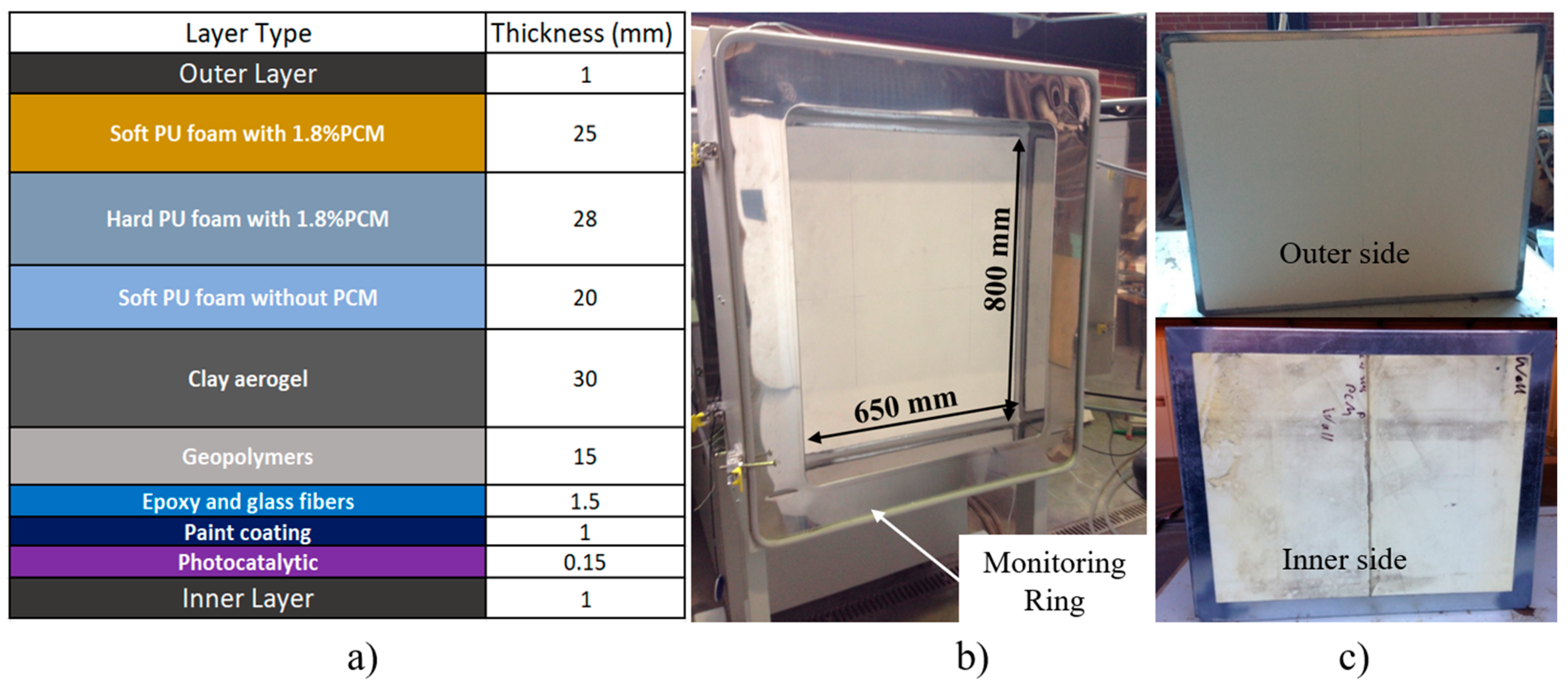
The multifunctional facade panel is constituted by the following layers, each providing a different functionality within the final multilayer panel configuration.
Figure 1a) represents the scheme of the multifunctional panel and the position of the corresponding layers, and
Figure 1b) illustrates the overall dimensions of the multifunctional panel. The properties of the various materials can be consulted in
Table 1 The pristine PCM was synthesized according to Amaral et al [
22] and the
Table 2 lists its principal properties. More specifically, the multifunctional facade panel is constituted by the following layers with specific functionality:
The anchoring layer, formed by three separate polyurethane layers. The soft polyurethane (PU) foam layer that will be compressed against the outer or existing back wall, covering defects and protrusions. The hard PU foam layer will support the thermal insulation and mechanical stability of the panel. These two layers incorporate a low percentage of PCM in weight (1.8 wt%). Finally, an inner soft PU foam layer without PCM will protect the adjacent insulation layer (aero clay);
The main insulation layer of the façade providing thermal and acoustic insulation (clay/silica aerogel layer);
The durable layer, which protects the inside layers from humidity, provides mechanical properties and fire protection of the component (geopolymer layer);
The external layer providing flame retardancy and mechanical stability (fiber-reinforced polymer layer);
The intumescent layer providing fire protection and anti-corrosion properties (intumescent fire layer);
The surface coating provides the final aesthetics of the panel and photocatalytic properties (paint coating).
Figure 1.
Multifunctional facade a) layer layout constitution in mm, b) dimensions of the tested panel and c) outer and inner aspect.
Figure 1.
Multifunctional facade a) layer layout constitution in mm, b) dimensions of the tested panel and c) outer and inner aspect.
Table 1.
Final properties of the multifunctional facade panel.
Table 1.
Final properties of the multifunctional facade panel.
| PANEL LAYERS |
MATERIAL |
THICKNESS
(MM) |
DENSITY
(KG/M3) |
THERMAL CONDUCTIVITY (W/M.K) |
SPECIFIC HEAT (J/KG.K) |
| SOFT PU FOAM LAYER |
Soft PU foam with 1.8%PCM |
25 |
101 |
0.037 |
- |
| HARD PU FOAM LAYER |
Hard PU foam with 1.8%PCM |
28 |
98 |
0.037 |
- |
| SOFT PU FOAM LAYER |
Soft PU foam without PCM |
20 |
101 |
0.037 |
1327 |
| INSULATION LAYER |
Clay aerogel |
30 |
50 |
0.035 |
850 |
| DURABLE LAYER |
Geopolymers |
15 |
1050 |
0.169 |
1000 |
| EXTERNAL LAYER |
Epoxy and glass fibres |
1.5 |
1870 |
0.320 |
1500 |
| INTUMESCENT LAYER |
Paint coating |
1.0 |
1500 |
0.200 |
1500 |
| SURFACE COATING |
Photocatalytic |
0.15 |
1100 |
0.035 |
1500 |
Table 2.
Properties of the PCM solely.
Table 2.
Properties of the PCM solely.
| Density (kg/m3) |
Melting |
Thermal conductivity (W/m.K) |
Transition temperature
Tt,m (°C) |
Melting temperature
Tm (°C) |
Melting latent heat
ΔHm (J/g) |
10ºC |
20ºC |
| 503 |
23.37 |
25.84 |
59.56 |
0.970 |
1.051 |
2.2. Hot box method
The hot box method is based on the steady-state method and consists in a relatively stable thermal environment using a simple hot box setup [
23,
24,
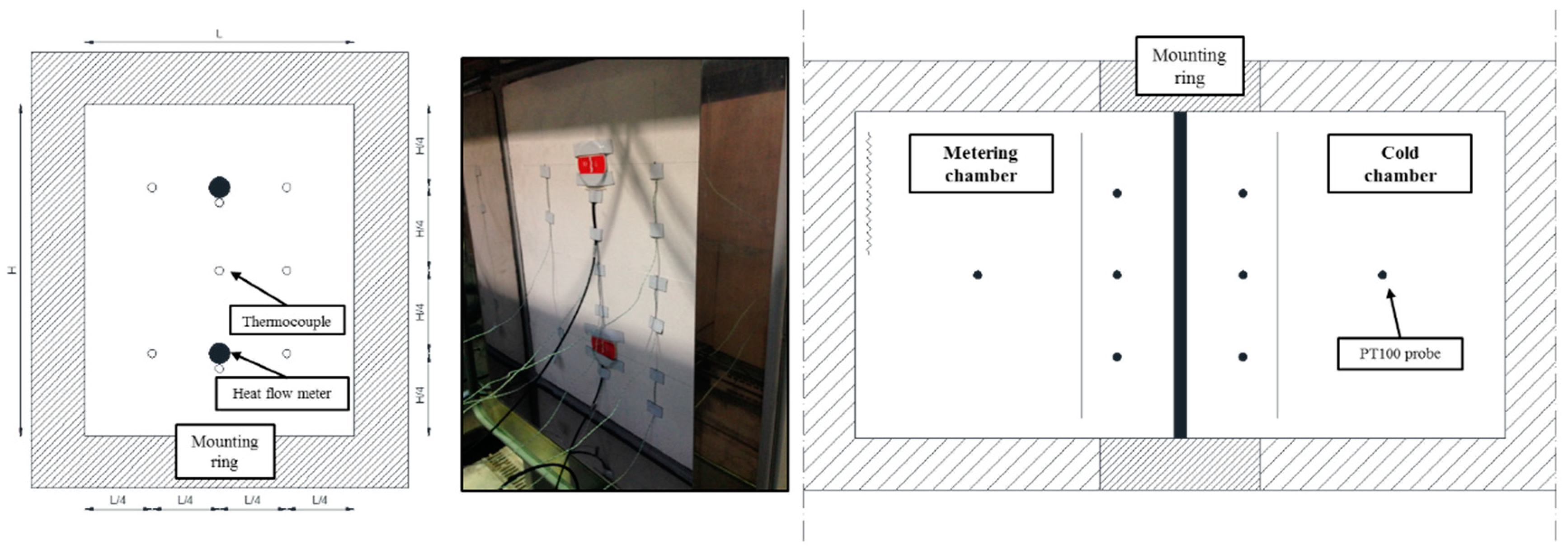
25]. Each hot box configuration has two closed chambers that keep a controlled temperature and relative humidity condition: one of the chambers is at a low and constant temperature (cold chamber) and, the other, the metering chamber is placed at higher and constant temperature (warm chamber). Between the two chambers is fixed a mounting ring (see
Figure 1b) with the panel specimen to be tested [
25,
26,
27]. The detailed procedure, schemes and materials are described in Amaral et al [
28,
29].
The dimensions of the panel for thermal properties evaluation are 800x650 mm (height x width) with a thickness of 122.65 mm (see
Figure 1a,b). These dimensions are limited by the hot box mounting ring structure geometry (maximum internal dimensions are 800x650x390 mm). The climatic chambers and specimen surface were monitored using thermocouples and heat flux meters on the panel specimen as shown in
Figure 2.
Figure 2 presents the sensors positioning and quantities on each specimen surface (exterior and inner side). Eight T-type thermocouples and two heat flux meters were placed on the considered external surface of the specimen (warm chamber side). On the internal surface of the specimen, eight T-type thermocouples measured the internal chamber and specimen surface temperatures, as well as heat flux meters in the same position opposite to the others placed. Five PT100 probes at a distance of 150 mm from the specimen (cold and warm chambers) and one PT100 probe was placed in the middle of the chamber (cold chamber side). In the warm chamber, six PT100 probes were positioned oppositely in the same relative position.
2.3. Experimental results
2.3.1. Temperature amplitude
The equivalent thermal conductivity (λ) of the whole panel is calculated according to the Fourier´s Law, using the following equation:
Where q is the measured horizontal heat flux through the specimen in steady-state in W/m²; s is the thickness of the specimen in m; ΔT is the difference between the specimen surface temperature in °C. The global thermal transmittance can be calculated by:
For measuring the thermal transmittance, the temperature of the chambers, was separately set to the following pair temperatures (which means: [temperature of the cold chamber; temperature of the warm chamber]) in ºC: [2;12], [4;14], [6;16], (…), [30;40].
For 6 hours at each temperature difference step, summing up to a total amount of 15 steps of measurements.
Figure 3 shows the experimental values determined for the thermal conductivity and thermal transmittance versus the mean temperature of the surface temperature of both sides for the multifunctional facade panel tested. A fairly good relationship was observed between the thermal conductivity and the thermal transmittance and the increasing mean surface temperature of the specimen. The square correlation coefficient (R
2) obtained is 0.942, which corroborates a good accuracy of the linear fitting. The thermal conductivity values obtained were between 0.0326 and 0.0609 W/m.K and the thermal transmittance values obtained were between 0.2719 and 0.5077 W/m
2.K for a mean temperature ranging from 12.16 ºC to 39.92 ºC. During the PCM phase change transition stage a slight decreasing trend with the increasing mean temperature of the specimen was registered, it can be found that as the solid-liquid phase change temperature range of the PU foam with PCM was about 20-23 °C, part of the PU foam would experience phase change when the temperature rises from 15 °C to 25 °C. However, the effect on the thermal conductivity and thermal transmittance profiles with the incorporation of the PCM is not visible, acknowledging that the percentage of PCM incorporated is very low (1.8% in weight), however this feature will be numerically assessed with a calibrated model in section 3.
2.3.2. Thermal amplitude results
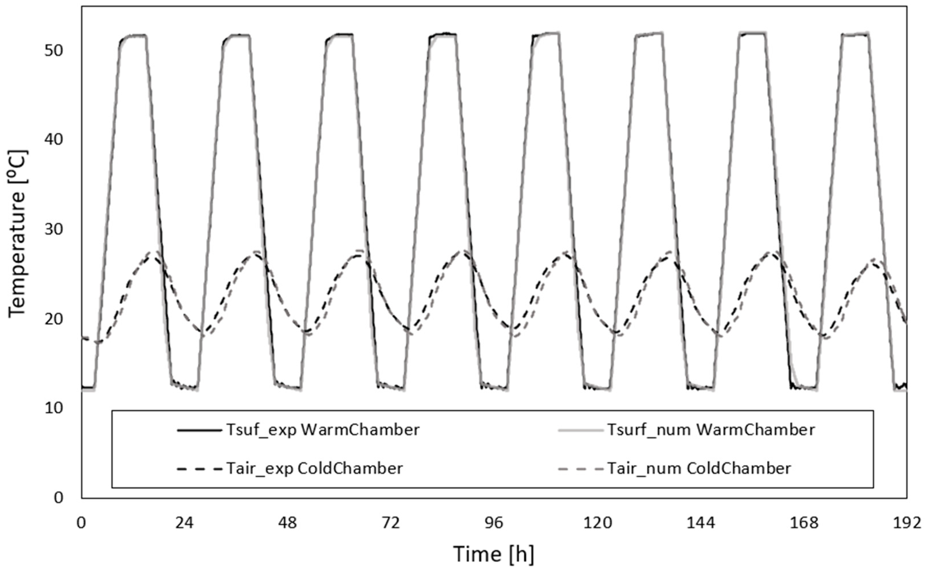
To evaluate the reduction of thermal amplitude between a simulated exterior conditions and indoor environment (warm and cold chambers), the temperature of the cold chamber was left to free float temperature conditions and the temperature of the warm chamber was set to impose a temperature curve profile between 12 °C and 52 °C for 24 hours at each step, that is a total amount of 8 timesteps of measurements carried out (see
Figure 4). This covers a large range of the Mediterranean climate context. The experimental results of the temperature profiles for the chambers and specimen surfaces are shown in
Figure 4. The air temperature measurements in the warm chamber are very similar to the specimen surface temperature in the warm chamber, but in the cold chamber the results reveal a small difference between these temperatures. These differences are due to the cold chamber being set at a free float temperature condition.
The cold chamber curve profile obtained ranges between 18 ºC and 30 °C for a imposed temperature profile between 12 ºC and 52 ºC in the warmer chamber. Comparing the temperature curves (exterior – warm chamber and indoor – cold chamber) it can be observed that the thermal amplitude reduction is very significant, specifically for the maximum and minimum peak temperatures in this specific operating conditions.
3. Numerical models
In order to access the thermal performance of the studied panel, several numerical models were developed, and simulations were performed. Experimental data from the previous sections were used. A geometrical model of the experimental setup was used to validate and calibrate the numerical model, as discussed in the next section.
3.1. Numerical definitions
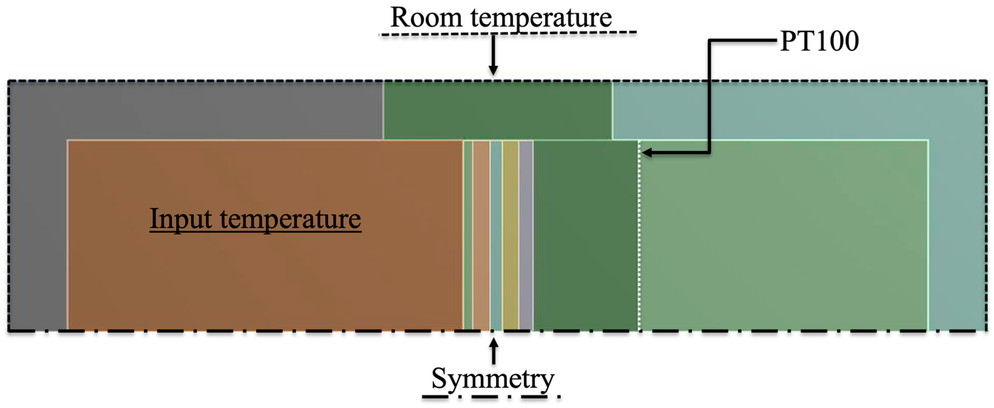
Recurring to Ansys Workbench v14, a 2D finite element model was developed to simulate the experimental transient thermal testing conditions. The symmetry of the geometry, specimen composition and boundary conditions allowed for the use of a smaller middle cross-section model cutting booth chambers and mounting ring where the specimen is mounted (
Figure 5), which will significantly reduce the necessary computational time.
The multifunctional facade panel is located in between the two chambers at the centre of the model formed by layers listed in
Figure 1a). A surface divides the cold chamber in two parts to represent the position of the PT100 probes at a distance of 150 mm from the panel (“PT100”). The chamber consists of three regions: the cold chamber, the mounting ring, and the warm chamber as shown in
Figure 5. The chamber walls are composed by three layers: an inner steel sheeting, a rockwool insulation, and an external zinc sheeting with protection. The thickness of these three layers is 1.5 mm, 125 mm and 1.5 mm respectively. The boundary conditions introduced in the problem are i) the symmetry plane at the bottom (“Symmetry”), ii) the uniform temperature at the external boundary (“Room temperature”), and iii) the warm chamber (“Input temperature”) as shown in
Figure 5.
The materials, thickness, and thermal properties of the facade panel were listed in
Figure 1. The material properties of the chamber walls are shown in
Table 2.
The specific heat of the soft foam layer with PCM and the hard foam layer with PCM, designated as
cmix, has been calculated considering the PCM mass fraction,
fw.
Where
cfoam is the specific heat of the base layer and
cPCM is the specific heat of the PCM. The fusion temperature of the PCM is 21-22°C. The specific heat of the foam layer with PCM during the phase change is equal to:
Lv is the latent heat phase change of PCM. The internal air is modelled as a fluid in laminar regime.
Table 2.
Material Properties.
Table 2.
Material Properties.
| Chamber material |
Thickness (mm) |
Density (kg/m3) |
Thermal conductivity (W/m.K) |
Specific heat (J/kg.K) |
Viscosity (mm) |
| Galvanized steel |
1.5 |
7833 |
54 |
465 |
- |
| Rockwool |
125 |
70 |
0.0375 |
840 |
- |
| Zinc |
1.5 |
7144 |
112.2 |
384.3 |
- |
| Interior air |
- |
7833 |
54 |
465 |
1.5 |
3.2 Numerical validation with experimental results
The input of the model is the room temperature variation (around the chambers in laboratory conditions) and the experimental temperature curve versus time of the warm chamber. The former is a trapezoidal temperature wave that ranges between 12 °C and 52 °C, with a period equal to one day cycle of 6 hours steps. A total of eight days is considered for the numerical simulation. The room temperature is around 18 °C±2 ºC. The input temperature was taken from the experimental thermocouples placed in the warm chamber, and the room temperature was taken from a reference thermocouple in the laboratory near the chambers.
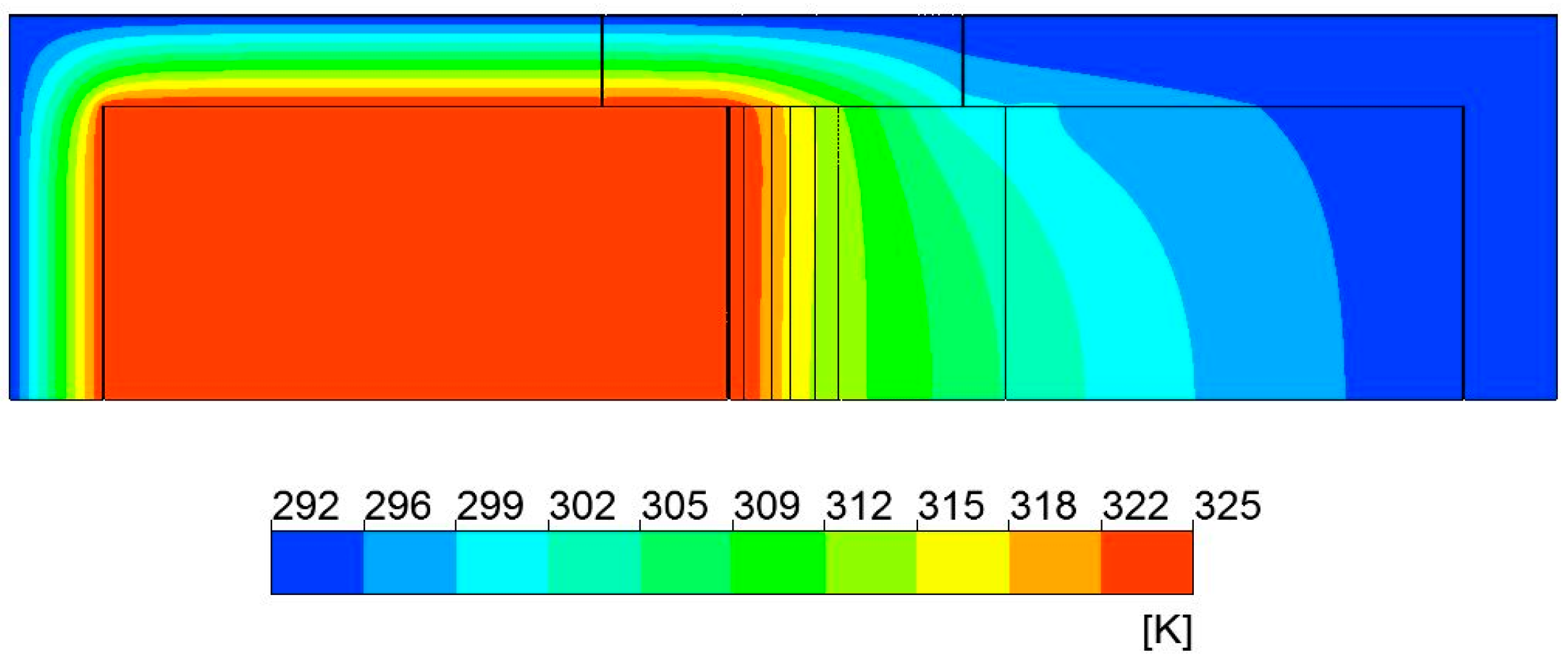
Figure 6 shows an example of the temperature contours for the timestep when the imposed input temperature is maximum (52 ºC=325.15 K).
The final output is the temperature curve in the cold chamber, the average temperature taken from the PT 100 probes positioned 150 mm away from the panel in the cold chamber. The numerical and experimental temperature profiles show a good agreement (see
Figure 7).
To assess the accuracy of the numerical model, the goodness-of-fit (GOF) criteria and the correlation factor R2 indicator were utilized.
3.2.1. Statistical indices
The GOF [
30] indicator is a dimensionless index which allow us to evaluate the calculated results with the measured results. The methodology and equations to calculate GOF can be consulted in [
28].
Once calculated the GOF indicator, smaller values of this statistical indicator represent the parameters that provide a closer match between measured data and simulated results.
Table 3 presents the calculated statistical indices. For each index, the results that present the best agreement between the experimental and numerical data are presented below:
According to Cipriano et al.[
30] a GOF lower than 11% is recommended for trial agreement, so the overall results are acceptable.
3.2.2. Correlation factor, R2
Another approach to evaluate the agreement between the experimental and numerical data is the average of the correlation factor, R
2.
Figure 8 presents a scatter plot between the experimental specimen data and numerical results of the model in indoor – cold chamber.
The comparison between the numerical and experimental data presented good agreement with a correlation factor of 0.9674 for the best/optimized model.
3.3. Numerical results
Once the model was validated with experimental data, a parametric calculation was performed to evaluate and analyse the function, performance, and optimum working conditions of the PCM multifunctional facade panel. The input variables defined were i) the mass fraction of PCM, ii) the warm chamber mean temperature, iii) the warm chamber amplitude temperature, and iv) the room temperature. These variables can range as follows:
PCM mass fraction: 0%, 1.8%, 5% and 10%;
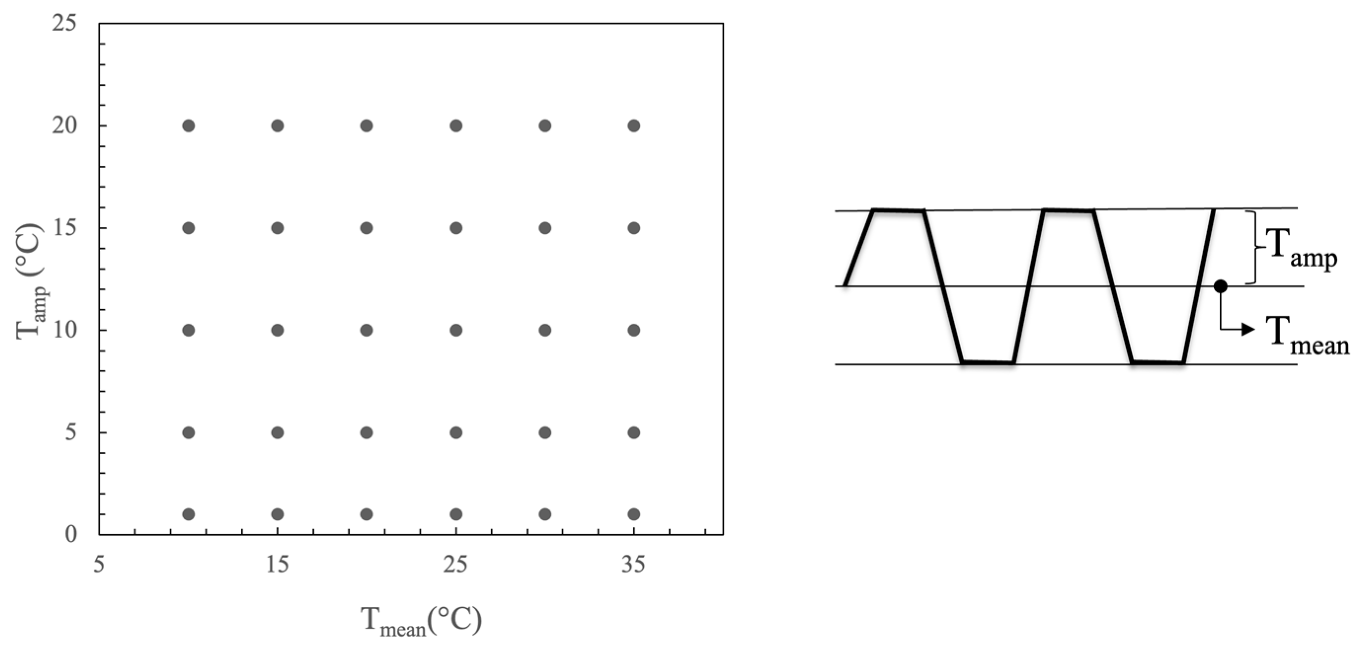
External mean temperature Tmean: 10 °C, 15 °C, 20 °C, 25 °C, 30 °C and 35 °C;
Temperature amplitude, Tamp: 1 °C, 5 °C, 10 °C, 15 °C and 20 °C;
Room temperature: 18 °C and 20 °C.
Combining the four variables there are 240 combinations to be studied, this is, to be simulated. For each of these combinations, the decrement factor,
f, is defined as the ratio between the temperature amplitude of the output with PCM relative to the temperature amplitude without PCM and can vary between 0 and 1:
ΔT
Panel with PCM is the amplitude of the temperature output curve at the specimen surface on the cold side where the experimental thermocouples have been placed. This value is calculated for the mass fraction of PCM equal to 1.8%, 5% and 10%. ΔT
Panel without PCM is the amplitude of the temperature output curve of the specimen surface corresponding to 0% PCM (reference case). The ratio is a magnitude that quantifies the performance of the PCM and if equal or near to 1 this means that PCM is not operating (charging and discharging). The optimum working conditions of PCM correspond when the decrement factor is minimum. The numerical model is the same used in the validation phase of the model. The differences are i) the room temperature is constant, ii) the PCM fraction varies, and iii) the input temperature curve is a trapezoidal temperature wave of period equal to 1 day and defined by steps of 6-hour duration. The point matrix is formed by the mean temperature and the amplitude as shown in
Figure 9 Calculations have been performed automatically using a Python Programming Language script integrated into Ansys Workbench developed by the authors.
The results are represented as temperature contour plots as shown in
Figure 10. The contour images, constructed with 240 thermal transient calculations, show the effect of PCM through the created indicator - decrement factor (between 0 and 1). The efficiency of the panel can improve by nearly 50% depending on the input boundary conditions. There is a temperature region near the peak melting temperature of the PCM where the performance of the panel is maximum. The efficiency of the panel and the size of the optimum region increases with the PCM fraction growth. The optimum amplitude of the input temperature varies also with the PCM content, greater values allow to store and release higher amounts of energy leading to lower decrement factors. The thermal response is smoothed out by the PCM melting and solidifying process. The behaviour is optimum when the input mean temperature is near 20 °C for a room temperature of 18-20 °C.
4. Conclusions
This work presented and discussed the results of an experimental campaign and parametric numerical simulation of a multifunctional facade panel with PCM. The panel´s thermal characteristics and the potential as a thermal regulator of indoor spaces have been assessed through laboratory testing (hot box heat flux meter method) and numerical simulation (using Ansys Fluent).
The experimental results show that the values of the equivalent thermal conductivity and thermal transmittance for temperatures below and above the PCM phase change transition zone increase with the increasing temperature; however, during the PCM phase change transition, a decreasing trend of the thermal characteristics with the increasing temperature is observed.
Comparing the experimental results obtained for the exterior and indoor temperatures, it was registered, that even though the small percentage of incorporated PCM it has revealed to reduce the thermal amplitude.
A numerical model has been developed to evaluate the effect of the PCM incorporated into the panel under a wide range variables and combination of boundary conditions. The simulations developed using Ansys Fluent have been validated comparing the numerical results with the experimental data and a good agreement was obtained.
The behaviour of the panel is the best when the external mean temperature and the internal temperatures are near the melting peak temperature of the PCM.
From the numerical parametric study increasing the PCM quantity leads to an improvement of the overall thermal performance. In this case, considering the temperature amplitudes of the testing, the thermal regulation capacity reached from the melting and solidification process is enhanced.
Further numerical modelling should be developed to assess new combinations of different PCMs with different melting temperatures.
Acknowledgements
This article was supported by the projects UIDB/00481/2020 and UIDP/00481/2020 - Fundação para a Ciência e a Tecnologia; and CENTRO-01-0145-FEDER-022083 - Centro Portugal Regional Operational Programme (Centro2020), under the PORTUGAL 2020 Partnership Agreement, through the European Regional Development Fund. Thanks are due to University of Aveiro and the Foundation for Science and Technology (FCT) - Risks and Sustainability in Construction (RISCO), Universidade de Aveiro, Portugal [FCT/UIDB/ECI/04450/2020].
Nomenclature
| cfoam
|
specific heat of the base layer (J/(kg.K)) |
| cmix
|
specific heat (soft foam layer with PCM + hard foam layer with PCM) (J/(kg.K)) |
| cPCM
|
Specific heat of the PCM (J/(kg.K)) |
| f |
decrement factor |
| fw
|
PCM mass fraction |
| Lv
|
latent heat phase change of PCM |
| q |
heat flux (W/m²) |
| s |
thickness (mm) |
| T |
temperature (ºC) |
| Tamp
|
amplitude temperature (ºC) |
| Tmean
|
external mean temperature (ºC) |
| U-value |
thermal transmittance (W⁄(m2.K)) |
| Greek letters |
| Δ |
amplitude |
| λ |
thermal conductivity (W/m.K) |
| Abbreviations |
| CV RMSE |
coefficient of variation of the root mean square error |
| ECR |
energy consumption reduction |
| GOF |
goodness-of-fit |
| IEA |
International Energy Agency |
| NBME |
normalized mean bias error |
| PCM |
phase change materials |
| R2
|
correlation factor |
| RMSE |
root mean square error |
| PU |
polyurethane |
| TES |
thermal energy storage |
| wt |
weight |
References
- S. Ramakrishnan, X. Wang, J. Sanjayan, and J. Wilson, “Thermal performance of buildings integrated with phase change materials to reduce heat stress risks during extreme heatwave events,” Appl. Energy, vol. 194, pp. 410–421, May 2017. [CrossRef]
- S. Roaf, L. Brotas, and F. Nicol, “Counting the costs of comfort,” https://doi.org/10.1080/09613218.2014.998948, vol. 43, no. 3, pp. 269–273, May 2015. [CrossRef]
- N. Fumo and M. A. Rafe Biswas, “Regression analysis for prediction of residential energy consumption,” Renew. Sustain. Energy Rev., vol. 47, pp. 332–343, 2015. [CrossRef]
- Z. Zhou, C. Wang, X. Sun, F. Gao, W. Feng, and G. Zillante, “Heating energy saving potential from building envelope design and operation optimization in residential buildings: A case study in northern China,” J. Clean. Prod., vol. 174, pp. 413–423, Jan. 2018. [CrossRef]
- S. A. Memon, “Phase change materials integrated in building walls: A state of the art review,” Renew. Sustain. Energy Rev., vol. 31, no. 0, pp. 870–906, 2014. [CrossRef]
- E. Zavrl, M. El Mankibi, M. Dovjak, and U. Stritih, “Enhancing performance of building elements with phase change materials for cooling with air-based systems,” J. Energy Storage, vol. 51, p. 104461, Jul. 2022. [CrossRef]
- ISO, “ISO 7345:1987(en), Thermal insulation — Physical quantities and definitions.” .
- D. Bienvenido-Huertas, J. Moyano, D. Marín, and R. Fresco-Contreras, “Review of in situ methods for assessing the thermal transmittance of walls,” Renew. Sustain. Energy Rev., vol. 102, pp. 356–371, Mar. 2019. [CrossRef]
- T. R. Whiffen and S. B. Riffat, “A review of PCM technology for thermal energy storage in the built environment: Part I,” Int. J. Low-Carbon Technol., vol. 8, no. 3, pp. 147–158, Sep. 2013. [CrossRef]
- T. Silva, R. Vicente, C. Amaral, and A. Figueiredo, “Thermal performance of a window shutter containing PCM: Numerical validation and experimental analysis,” Appl. Energy, vol. 179, pp. 64–84, Oct. 2016. [CrossRef]
- Y. Xu, B. B. Sun, L. J. Liu, and X. Y. Liu, “The numerical simulation of radiant floor cooling and heating system with double phase change energy storage and the thermal performance,” J. Energy Storage, vol. 40, p. 102635, Aug. 2021. [CrossRef]
- B. Larwa, S. Cesari, and M. Bottarelli, “Study on thermal performance of a PCM enhanced hydronic radiant floor heating system,” Energy, vol. 225, p. 120245, Jun. 2021. [CrossRef]
- Y. Lin, S. Zhong, W. Yang, X. Hao, and C. Q. Li, “Multi-objective design optimization on building integrated photovoltaic with Trombe wall and phase change material based on life cycle cost and thermal comfort,” Sustain. Energy Technol. Assessments, vol. 46, p. 101277, Aug. 2021. [CrossRef]
- S. Soudian and U. Berardi, “Development of a performance-based design framework for multifunctional climate-responsive façades,” Energy Build., vol. 231, p. 110589, Jan. 2021. [CrossRef]
- M. Sovetova, S. A. Memon, and J. Kim, “Thermal performance and energy efficiency of building integrated with PCMs in hot desert climate region,” Sol. Energy, vol. 189, pp. 357–371, Sep. 2019. [CrossRef]
- P. K. S. Rathore, S. K. Shukla, and N. K. Gupta, “Yearly analysis of peak temperature, thermal amplitude, time lag and decrement factor of a building envelope in tropical climate,” J. Build. Eng., vol. 31, p. 101459, Sep. 2020. [CrossRef]
- P. K. S. Rathore and S. K. Shukla, “An experimental evaluation of thermal behavior of the building envelope using macroencapsulated PCM for energy savings,” Renew. Energy, vol. 149, pp. 1300–1313, 2020. [CrossRef]
- M. Bahrar, Z. I. Djamai, M. EL Mankibi, A. Si Larbi, and M. Salvia, “Numerical and experimental study on the use of microencapsulated phase change materials (PCMs) in textile reinforced concrete panels for energy storage,” Sustain. Cities Soc., vol. 41, pp. 455–468, Aug. 2018. [CrossRef]
- Q. Li et al., “Thermoeconomic analysis of a wall incorporating phase change material in a rural residence located in northeast China,” Sustain. Energy Technol. Assessments, vol. 44, p. 101091, Apr. 2021. [CrossRef]
- [20] C. Liu, G. Zhang, M. Arıcı, J. Bian, and D. Li, “Thermal performance of non-ventilated multilayer glazing facades filled with phase change material,” Sol. Energy, vol. 177, pp. 464–470, Jan. 2019. [CrossRef]
- X. Zhao, S. A. Mofid, M. R. A. Hulayel, G. W. Saxe, B. P. Jelle, and R. Yang, “Reduced-scale hot box method for thermal characterization of window insulation materials,” Appl. Therm. Eng., vol. 160, Sep. 2019. [CrossRef]
- C. Amaral et al., “Development of polyurethane foam incorporating phase change material for thermal energy storage,” J. Energy Storage, vol. 28, p. 101177, 2020. [CrossRef]
- X. Meng, Y. Gao, Y. Wang, B. Yan, W. Zhang, and E. Long, “Research paper,” Appl. Therm. Eng., vol. C, no. 83, pp. 48–56, May 2015. [CrossRef]
- C. Guattari, L. Evangelisti, P. Gori, and F. Asdrubali, “Influence of internal heat sources on thermal resistance evaluation through the heat flow meter method,” Energy Build., vol. C, no. 135, pp. 187–200, Jan. 2017. [CrossRef]
- X. Wang, H. Yu, L. Li, and M. Zhao, “Research on temperature dependent effective thermal conductivity of composite-phase change materials (PCMs) wall based on steady-state method in a thermal chamber,” Energy Build., vol. 126, pp. 408–414, 2016. [CrossRef]
- F. Asdrubali and G. Baldinelli, “Thermal transmittance measurements with the hot box method: Calibration, experimental procedures, and uncertainty analyses of three different approaches,” Energy Build., vol. 43, no. 7, pp. 1618–1626, Jul. 2011. [CrossRef]
- C. Buratti, E. Belloni, L. Lunghi, and M. Barbanera, “Thermal Conductivity Measurements By Means of a New `Small Hot-Box’ Apparatus: Manufacturing, Calibration and Preliminary Experimental Tests on Different Materials,” Int. J. Thermophys., vol. 37, no. 5, p. 47, Mar. 2016. [CrossRef]
- C. Amaral et al., “Experimental and numerical analysis of the thermal performance of polyurethane foams panels incorporating phase change material,” Energy, vol. 216, p. 119213, Feb. 2021. [CrossRef]
- C. Amaral, R. Vicente, V. M. Ferreira, and T. Silva, “Polyurethane foams with microencapsulated phase change material: Comparative analysis of thermal conductivity characterization approaches,” Energy Build., vol. 153, 2017. [CrossRef]
- J. Cipriano, G. Mor, D. Chemisana, D. Pérez, G. Gamboa, and X. Cipriano, “Evaluation of a multi-stage guided search approach for the calibration of building energy simulation models,” Energy Build., vol. 87, pp. 370–385, 2015. [CrossRef]
|
Disclaimer/Publisher’s Note: The statements, opinions and data contained in all publications are solely those of the individual author(s) and contributor(s) and not of MDPI and/or the editor(s). MDPI and/or the editor(s) disclaim responsibility for any injury to people or property resulting from any ideas, methods, instructions or products referred to in the content. |
© 2023 by the authors. Licensee MDPI, Basel, Switzerland. This article is an open access article distributed under the terms and conditions of the Creative Commons Attribution (CC BY) license (http://creativecommons.org/licenses/by/4.0/).
