1. Introduction
The service life of building structures is governed by the problem of concrete durability. Aggressive salts in the environment are a major cause of the deterioration of concrete properties. Especially sulfate attack is one of the main factors affecting the durability of concrete [
1,
2,
3,
4,
5,
6]. Sulfate ions could cause spalling of the concrete cover, corrosion of internal reinforcement, and reduction in load-bearing capacity, thus shortening the service life of the concrete structure. Besides, the occurrence of these damages was also accompanied by significant maintenance and protection costs. When exposed to a dry-wet cycle, concrete structures deteriorate at a pace that is significantly higher than the rate of deterioration observed when specimens are submerged for an extended period [
7]. Sulfate not only reacts with hydration products in concrete to produce expansive calcium alumina and gypsum, but also causes Ca
2+ dissolving, which would result in the deterioration of concrete properties [
8,
9,
10,
11].
The nanoparticles of appropriate size could fill the cementitious pores of cement hydration products and reduce the amount of cement-based materials [
12]. This can be attributed to the properties of the small particles and the high surface area-to-volume ratio of nanomaterials. In addition, the microstructures of cement-based materials could be optimized, the bonding strength between cement and aggregates could be improved, and the flaws of the internal cement-based materials could be addressed [
13,
14]. The discovery of carbon nanotubes (CNTs) in 1991 is considered to be one of the most important discoveries in the field of materials [
15]. Carbon nanotubes come in two forms, single-walled carbon nanotubes (SWCNT) or multi-walled carbon nanotubes (MWCNT). Both are well-structured graphene cylinders with an aspect ratio (the ratio of the length to the circumference of the cross-section) of 1000 or more [
16,
17,
18,
19]. Therefore, carbon nanotubes are ideal for reinforcing composite materials [
20]. MWCNTs are nanomaterials that exhibit excellent performance. MWCNTs significantly influence the macroscopic and microstructural characteristics of cement-based materials [
21,
22,
23,
24]. Besides, MWCNTs could improve the porosity and pore size distribution of cement-based materials by exploiting nano-filling and nucleating functions [
25,
26,
27]. MWCNTs could also strengthen the internal interface transition zone of cement-based materials and significantly lower the production of microcracks by exercising bridging effects [
28]. In addition to its composition, the mesoscopic structure of concrete also affects its performance. The fundamental component of the mesoscopic structure is the pore structure, which is strongly related to the macroscopic qualities of concrete, such as its ability to resist sulfate attack.
Research on carbon nanotube-cement matrix composites is still in the exploratory stage [
29,
30]. Scholars have found that the mechanical properties of carbon nanotube-cement matrix composites were closely related to the content of carbon nanotubes. Liu et al. [
31] investigated the effect of the optimum mix proportion and salt freezing durability of MWCNTs UHPC with different MWCNTs content and water binder ratio. The results showed that the optimum mix proportion was at a 0.19 water binder ratio and 0.1% carbon nanotube content. Compared to the control group, the compressive strength was increased by 34.1% and the flexural strength was increased by 13.6%. At 1500 salt freeze cycles, there was no change in the appearance and mass loss of the concrete and the microstructure remained relatively dense. Alicia et al. [
32] studied the effect of carbon nanotubes on the microstructure of cement pastes. The experimental results showed that the addition of CNT to plain cement accelerated the formation of hydration products. However, small changes in the amount of CNT added to the cement did not significantly alter the microstructure of the resulting cementitious material after the same curing process. The addition of CNT increased the rate of hydration of the specimens, leading to an acceleration of microstructure formation. Alastair et al. [
33] studied the durability of CNT-cement composites. The results showed that the initial water absorption of the cement paste at 0.1 wt% carbon nanotubes increased by 32% at 28 days compared to the reference cement paste. The optimal CNT content for enhancing resistance to chloride diffusion is 0.05-0.1 wt% Hawreen et al. [
34] analyzed the durability of concrete reinforced with different types and weight fractions of carbon nanotubes. The results showed that the use of 0.1 wt% MWCNTs increased the compressive strength by about 20%. Luo et al. [
35] investigated the effect of using 0.05-0.1 wt% carbon nanotubes on the performance of foam concrete. The tests yielded the ability of carbon nanotubes to reduce the average pore size and increase the compressive strength by approximately 30% compared to control specimens. According to Hu et al. [
36], the ideal MWCNT content is 0.1% of the cement mass, and under these dosage conditions, the porosity of the cement paste can be decreased by 27.52%. According to Liu et al.’s research [
37], MWCNTs not only boost the mechanical qualities of reactive powder concrete but also fill microscopic interior gaps and fissures, increasing the material’s resistance to sulfate assault.
Studies on the effect of sulfate attack on MWCNTs concrete are still very limited. In this paper, the effects of multi-walled carbon nanotubes (MWCNTs) on the mechanical properties and microstructure of lithium-slag concrete (LSC) during sulfate attack and drying-wetting cycles were investigated. The deterioration pattern of lithium-slag concrete under sulfate attack was investigated by studying the changes in morphology, compressive strength, and mass loss of multi-walled carbon nanotubes-lithium slag concrete. The microstructure of multi-walled carbon nanotube-lithium slag concrete (MWCNTs-LSC) was analyzed by scanning electron microscopy (SEM). The internal porosity, pore size distribution, sphericity and compactness were examined by X-ray computed tomography (CT) images.
2. Materials and Methods
2.1. Materials
The cementitious material used in this study are composite of P⋅O 42.5 ordinary Portland cement and lithium slag (LS), which was taken from the Urumqi lithium salt plant, dried and ground, and put into the experiment with a density of 2.48 g/cm
3 and a specific surface area of 417 m
2/kg. The main chemical composition of cementitious material were shown in
Table 1. The fine aggregate used in this study was river sand with an apparent density of 2641 kg/m
3 and a fineness modulus of 2.8. The coarse aggregate was continuously graded gravel with a particle size of 5–20 mm and an apparent density of 2687 kg/m
3. The water-reducing agent was a high-performance polycarboxylic acid water-reducing agent. The test water was taken from municipal tap water. The multi-walled carbon nanotubes chosen for this experiment were prepared by Chengdu Jiacai Technology Co., Ltd., following the CVD process. The physical parameters are shown in
Table 2. The sulfate solution was prepared from 5% anhydrous sodium sulfate by mass fraction.
2.2. Specimen Preparation
In total, 12 groups of MWCNT-LSC with different specimens were prepared, where the water-cement ratio (W/C) was varied as 0.35, 0.40, and 0.45, the content of MWCNT was 0 wt.%, 0.05 wt.%, 0.10 wt.%, and 0.15 wt.% of the cement mass, the mix proportions are shown in
Table 3, where 35, 40, 45 represented water-cement ratio 0.35, 0.40, 0.45, and 0, 5, 10, 15 represents MWCNTs dosing 0 wt.%, 0.05 wt.%, 0.10 wt.%, 0.15 wt.%. According to GB/T 50080-2016 [
38], the materials were placed in a 100 mm × 100 mm × 100 mm cube mold and shaken vigorously on a vibrating table. The specimens were maintained at a temperature of 20 ± 2 °C and relative humidity ≥ 95%.
2.3. Experiment Methods
2.3.1. Coupling of Sulfate Attack and Drying–Wetting Cycles Test
According to GB/T 50082-2009 [
39], the concrete specimens were cured under standard conditions for 26d, then taken out from the standard curing room, dried the surface moisture and put into the oven, and baked at 80 ± 5 °C for 48 h. and then cooled to room temperature, and then put into the sulfate test chamber with 5% sodium sulfate solution for dry and wet cycle test. The dry-wet cycle experiment was conducted using a CABR-LSB automatic concrete sulfate dry-wet cycle test machine. The specimens were immersed in sulfate solution for 15 h, air dried for 1 h, baked for 6 h at 80 ± 5 °C, and cooled throughout 2 h. The duration of one wet and dry cycle is 24 hours, with a total of 0, 30, 60, 90, 120 and 150 wet-dry cycles. During the experiment, the pH was maintained in the range of 6-8 and the pH of the solution was tested every 15 cycles. After reaching the set number of dry-wet cycles, remove the sample for drying.
2.3.2. Strength and Mass Loss Rate Test
The specimens were tested for compressive strength and quality at the end of every 30 times wet-dry cycles. The compressive strength was conducted using a YAW 2000 A electro-hydraulic servo pressure testing machine according to standard GB/T 50081-2019 [
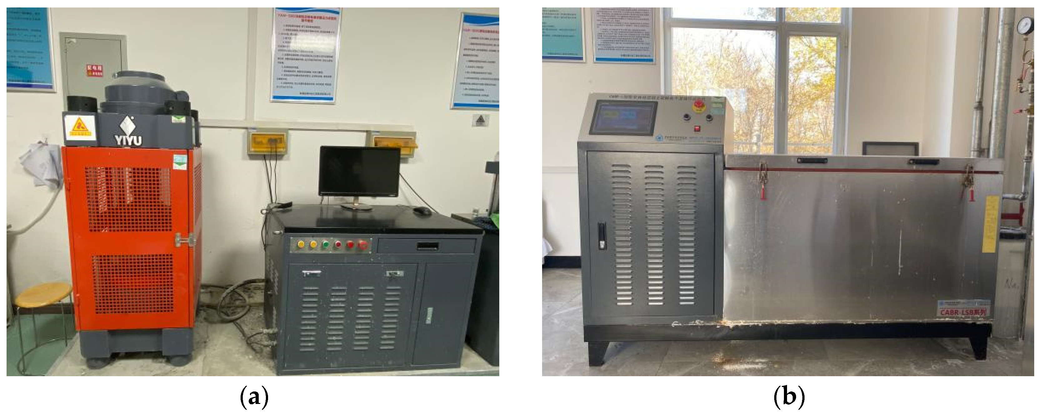
40]. A total of 0.5 MPa/s of the load was applied per second. The acquisition system logged the peak load during the test. Three specimens were tested for each group, and the average value was calculated. The primary apparatus used in the experiment were presented in
Figure 1. The concrete compressive strength,
fcc (MPa) and mass loss rate (%), were calculated by Equation (1) and Equation (2)
where P (N) is the peak load, A (mm
2) is the pressure area of the specimen.
where ΔW (%) is the mass loss rate of concrete after erosion, G
0 (g) is the initial mass of concrete before erosion, G
i (g) is the i-th measured mass of concrete after erosion.
2.3.3. Microstructure Test
The SU8010 scanning electron microscope from Hitachi, Japan was used to observe the microstructure of MWCNTs-LSC at different numbers of wet-dry cycles. The specimen size of the concrete test was about 8mm, and the non-observed surface was polished and glued to the conductive glue of the disc, followed by gold spraying.
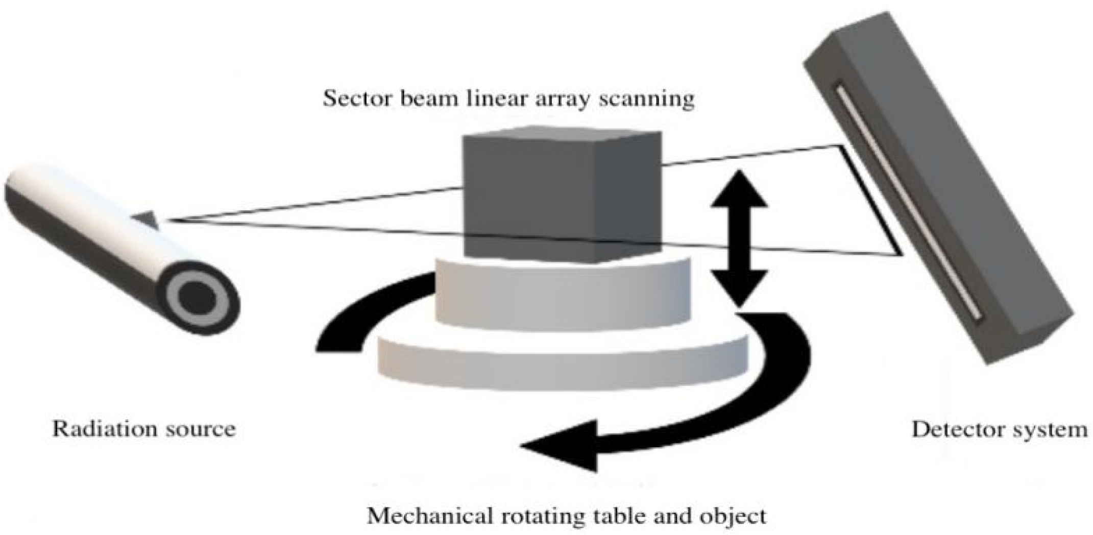
The pore structures of the MWCNTs-LSC specimens were investigated using X-ray computed tomography technology (CT). The concrete utilized in this CT test was scanned using YXLON company Y.CT COMPACT equipment (see
Figure 2). The scanning parameters were presented in
Table 4. Two elements dictate the performance of the fan-beam ICT scanning equipment: the line detector and the high-energy X-ray tube. During operation, the turntable and high-dose rays travel vertically in tandem with the rotating components, and an image is produced using attenuation data. The CT images were pre-processed using MATLAB tool functions and the IMAGE J machine learning plug-in. Image enhancement, denoising and image morphological processing were used to achieve the goal of image improvement and analysis. Image Proplus and VGStudio software were used to extract and count the relevant feature parameters for the pores.
3. Experimental Results and Discussion
3.1. Morphology Change
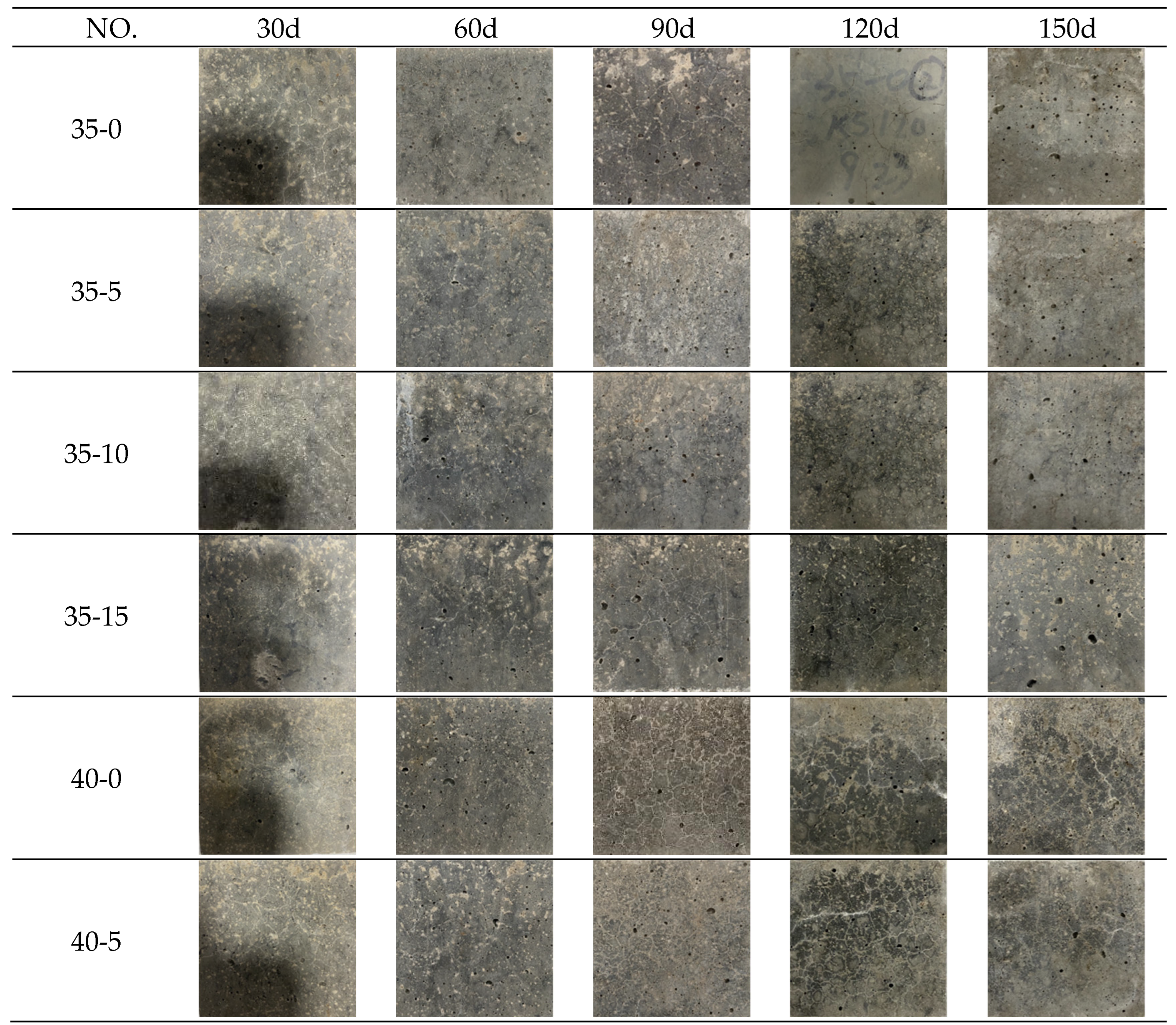
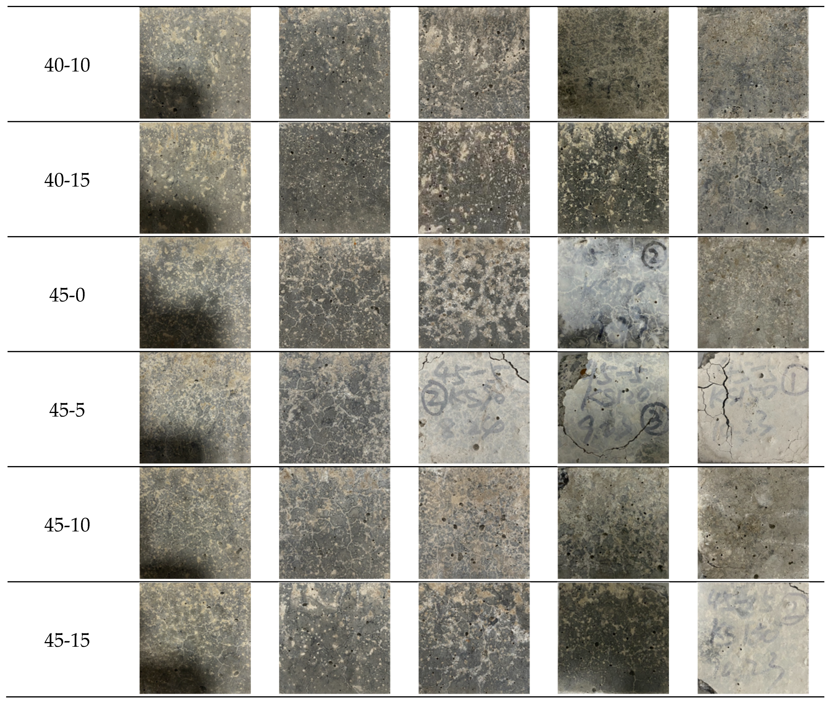
The specimens were observed for every 30 sulfate dry-wet cycling. The macroscopic morphology of specimens after 30, 60, 90, 120 and 150 sulfate dry-wet cycles was shown in
Figure 3. After 30 and 60 sulfate dry-wet cycles, some cracking was observed on the surfaces of the specimens, but there was no significant damage. However, some specimens had small pores due to the manufacturing method. After 30 sulfate dry-wet cycles, it can be observed that the specimen 35-0 has more cracks than the specimens 35-5, 35-10 and 35-15. After 60 sulfate dry-wet cycles, more cracks were observed in the specimen 45-0 than in the specimens 45-10 and 45-15. The addition of MWCNTs seemed to limit the deterioration of the concrete, as the specimens with MWCNTs had fewer cracks than those without MWCNTs. After 90 sulfate dry-wet cycles, the specimens are relatively intact in appearance. The surfaces of most specimens were covered with a yellowish-white powder, which was formed following the evaporation of the sulfate solution. but the surfaces of some specimens exhibited significant concrete spalling and cracking. The reason for this phenomenon was that the temperature of the drying state would reach 80 °C, leading to the evaporation of water and a sudden increase in the concentration of sodium sulfate solution inside the concrete. When the solution reached saturation, sulfate crystallization was produced and precipitated, i.e., the salt precipitation reaction on the surface of the specimens. In addition, large cracks were observed on the surface of specimen 45-5, accompanied by small pieces of concrete spalling at the corners. This is because under high W/C conditions, the bonding area between the slurry and the aggregate was reduced. After hardening, a large number of pores were formed to the extent that the compactness decreases. After 120 sulfate dry-wet cycles, cracks became apparent in the specimens 35-0 and 45-0. In addition, fewer cracks were observed in specimens with MWCNTs compared to those without MWCNTs. After 120 sulfate dry-wet cycles, all specimens exhibited a large number of pores. The LSC with 0.1 wt.% MWCNTs exhibited less severe damage, and few crystals were collected on the specimen surface. Fewer cracks and a low degree of corner dropout were observed in these conditions. The specimen with MWCNTs() had less number of cracks than the specimen 35-0 under the same W/C conditions. The specimen 45-0 had fewer cracks and more white crystals than the other specimens. Slags and corners were observed around the edges and corners of the surfaces of the specimen 45-5, as well as the leakage of aggregate particles. Specimen 35-0 had noticeably more pores than specimens 35-5, 35-10, and 35-15 than specimens containing MWCNTs under conditions of the same W/C. Specimen 40-0 had more cracks than those with MWCNTs. However, specimens 45-5 and 45-15 were severely damaged, and prominent cracks were formed. The corners were also damaged. Overall, the addition of 0.10 wt.% of MWCNTs improved the resistance of the concrete specimens to sulfate attack.
3.2. Compressive Strength
Figure 4.
Compressive strength of specimens after sulfate dry-wet cycles.
Figure 4.
Compressive strength of specimens after sulfate dry-wet cycles.
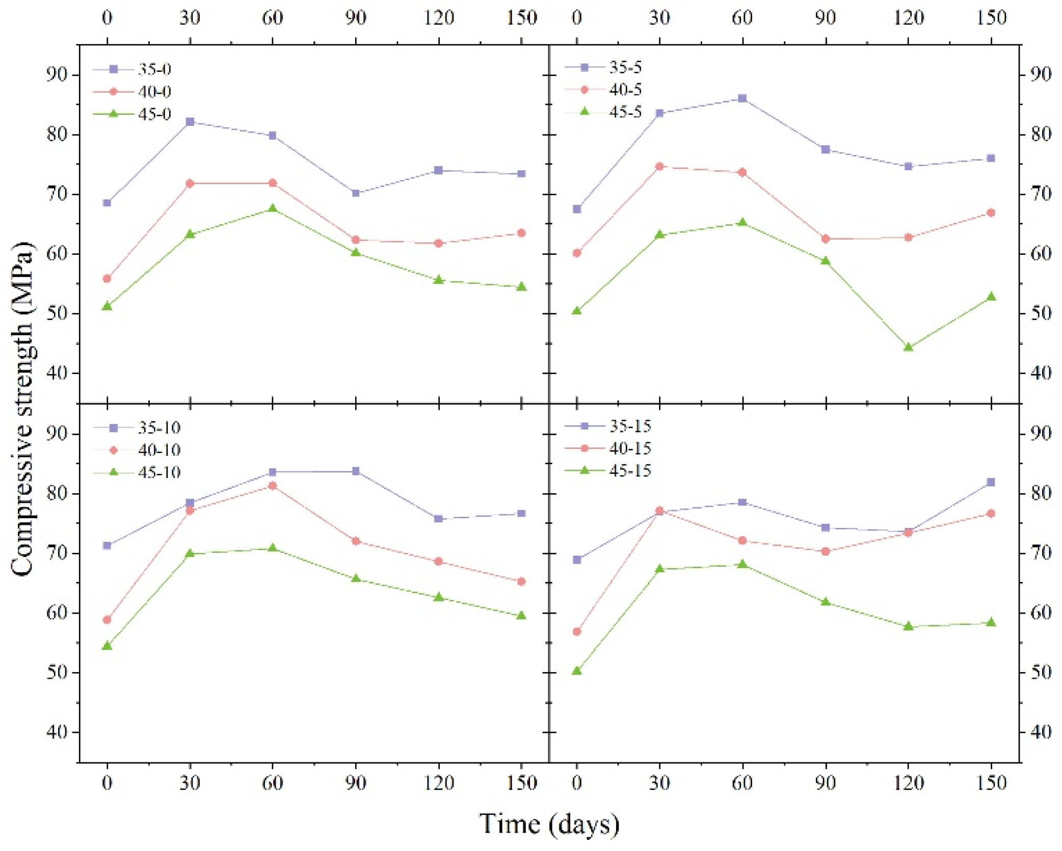
The compressive strength of MWCNT-LSC after 0, 30, 60, 90, 120, and 150 sulfate dry-wet cycles were presented in
Figure 4.
Figure 4 clearly showed that The initial compressive strength of specimen 35-10 was the maximum, which was recorded to be 71.3 MPa. At the same W/C, the compressive strength of the specimens containing MWCNTs was greater than that of the specimens without MWCNTs. As the number of sulfate dry-wet cycles rises, the compressive strength of the concrete also starts to increase.
The compressive strength, recorded in the presence and absence of MWCNTs and at different W/C LSC conditions, increased significantly after 30 sulfate dry-wet cycles, where the maximum growth rate was 35.67%. During this period, sulfate ions enter the concrete and produce calcium alumina, which refills the pore structure of the concrete, thus allowing the compressive strength of the concrete to increase.
After 30 and 60 sulfate dry-wet cycles, as the number of cycles rises, the compressive strength of the part of the specimens kept rising while others start to decrease. The compressive strength of all specimens with 0.10 wt.% MWCNTs continued to increase. This phenomenon might be caused by the filling of the pores at the interior of the specimens with MWCNTs. This helps improve the pore structure of concrete, promote hydration, and increases the compactness of the specimens. MWCNTs may also fill the internal pores of concrete because of small size. Additionally, the bridging effect could limit the generation of corrosion products, hinder the development of microcracks, and prevent the deterioration of the compressive strength.
However, the compressive strengths of all the specimens began to decrease after 60 sulfate dry-wet cycles due to the increase in the extent of corrosion at this point. The pores were gradually filled, altering the internal structure of the concrete and increasing its compactness. SO42– reacted with calcium hydroxide and hydrated calcium aluminate to form ettringite, and the solid phase volume increased, which resulted in the generation of a large amount of expansion stress inside the concrete.
3.3. Mass Loss Rate
Figure 5.
The mass loss rate of specimens after sulfate dry-wet cycles.
Figure 5.
The mass loss rate of specimens after sulfate dry-wet cycles.
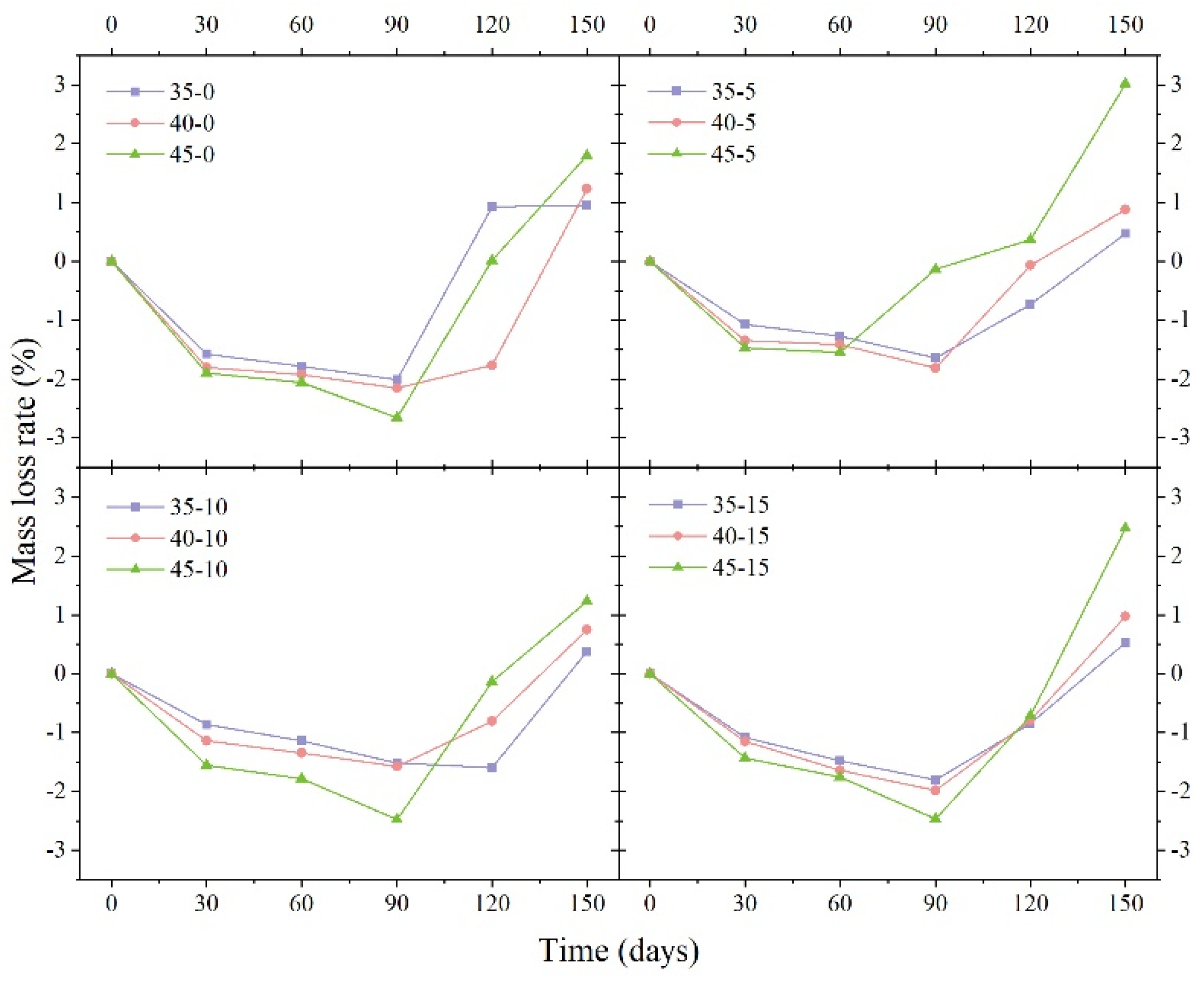
Figure 5 shows the mass loss rate of each specimen under various sulfate dry-wet cycling. The mass loss rate increased at the beginning of the test and then decreased as the number of cycles increased. The mass loss rate was negative for all specimens until 90 sulfate wet-dry cycles, indicating that the quality of the concrete increased with the number of sulfate wet-dry cycles. This phenomenon occurred due to the chemical reaction between the salt crystallization and the salt ions inside the concrete. Also, the evaporation of the solution from the surface of the concrete facilitated this process. Sulfate remained present in trace concentrations on the surface of the concrete. After 90 sulfate wet-dry cycles, the mass loss rates of most specimens began to rise due to the expansion of secondary hydration products within the concrete. This expansion led to fractures and the widening of cracks, causing the aggregate to flake off and the deterioration in the quality of the specimens. The density of the concrete decreased due to a reduction in the content of the calcium silicate hydrate gel. After 150 sulfate wet-dry cycles, the mass loss rates were all positive, indicating that the quality of the concrete was decreasing rapidly. This is mainly due to the erosion of the specimens under the action of sulfate, which results in the expansion pressure being greater than the cementing force between the materials. It is clear that regardless of the amount of MWCNTs added, specimens with a W/C of 0.45 have greater mass loss than those with a W/C of 0.40. 45-10 specimens were looser and had greater mass variation compared to those with a W/C value of 0.35. This indicates that a large amount of sulfate has the potential to penetrate into the interior of the concrete where it precipitates as sulfate crystals, increasing the mass of the concrete. At the same W/C conditions, the mass variation was more pronounced for the specimens without MWCNTs than those with MWCNTs. The other experimental groups with MWCNTs showed a slow increase in mass loss rate throughout the process. This was not the case for the specimens 45-5 and 45-15, which were significantly disrupted.
3.4. SEM
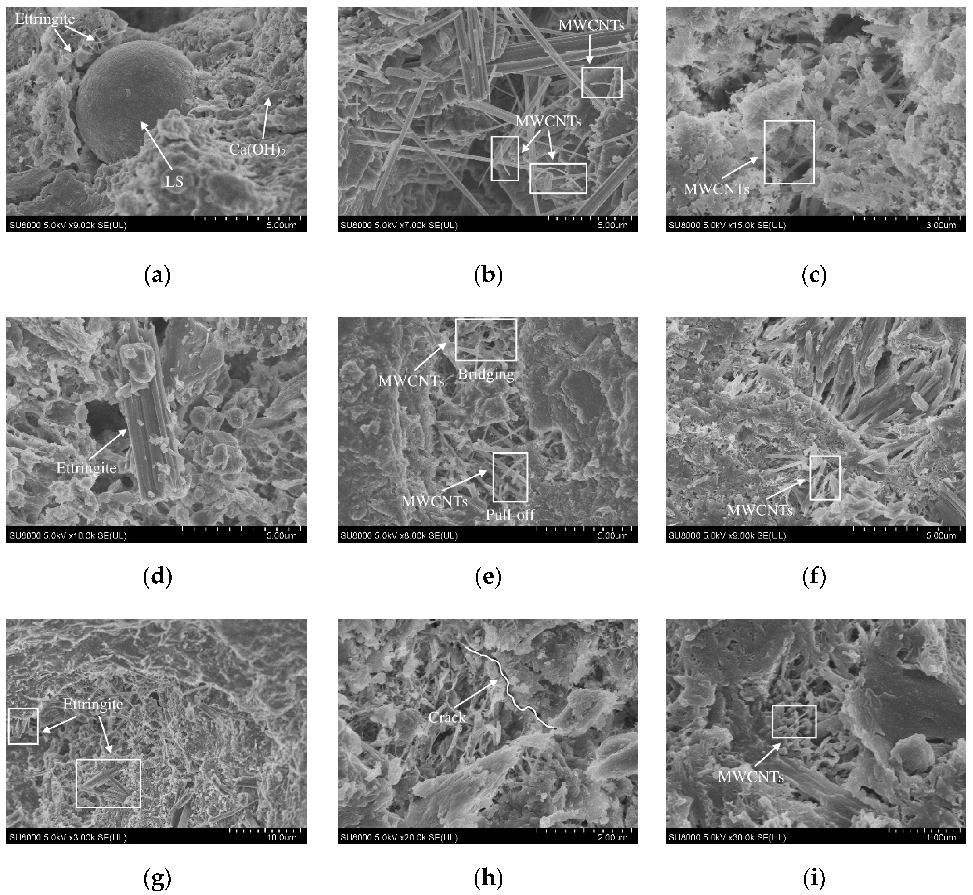
The microstructures of MWCNTs-LSC under sulfate dry-wet cycling were shown in
Figure 6. It can be seen from
Figure 6 that most of the multi-walled carbon nanotubes were bridged with the hydration products in the form of single laps, forming multiphase composites and improving the mechanical properties of the concrete. As can be seen from the microstructure of the concrete before the sulfate dry-wet cycling, unhydrated LS particles were present inside the specimens without MWCNTs, while for the specimens with MWCNTs, the MWCNTs were dispersed between the cracks within the concrete specimens and bridged, acting as a strong reinforcement. As the W/C increased, more cracks and pores appeared in the internal structure, but it was evident that MWCNTs formed bridges between the cracks. After 150 sulfate dry-wet cycles, the specimens were all damaged to some extent internally, the cracks expanded, the connections between the hydration products became loose and honeycombed, and the structure was gradually loosened and destroyed internally. The internal structure of the specimens without MWCNTs was looser, whereas the hydration products of the specimens with MWCNTs were still denser and did not show more obvious looseness or larger pores. The stable hydration and bridging effects were observed in the specimens with MWCNTs by SEM, a property that makes the concrete denser internally, leading to improved performance. This indicates that with the decrease of W/C, the incorporation of MMWCNTs acted as an inhibitor of crack development to improve the denseness of concrete, which effectively enhanced the sulfate resistance of MWCNTs-LSC.
3.5. CT
3.5.1. 2D Pore Structure Analysis
The interval between the CT scanning stages should be minimized to achieve high accuracy in subsequent modeling stages. This results in the generation of a very high number of CT scanning images of a single specimen. The pore structure was retrieved and evaluated by Image Proplus after 20 CT images were chosen at equal intervals along the scanning z-axis during the 2D study. Alternatively, a representative scanning segment was chosen every 5 mm. The fluctuation in the 2D porosity of the specimens along the depth of the z-axis is depicted in
Figure 7. It is clear that each specimen’s variation in 2D porosity changes with changes in the depth of the specimen. The porosity on the upper surface was in the range of 40-70 mm, and the value approached the average value.
Based on the two-dimensional porosity image shown in
Figure 7a–f, it was observed that at the same water-cement ratio and in the absence of sulfate attack, the porosity of the LSC without MWCNTs was lower than that of the specimens with MWCNTs. This is because MWCNTs make the cement mortar denser and more difficult to vibrate. However, the pores of the concrete become larger after vibrating. Therefore, the slurry with MWCNTs should be vibrated vigorously to improve the performance of MWCNTs. In contrast, the porosity of the LSC specimen without MWCNTs steadily increases as the number of sulfate dry-wet cycles rises. Meanwhile, the porosity of the LSC with MWCNTs decreases after 30 and 150 sulfate dry-wet cycles, which increased by 11.79% and 35.15%, respectively. The incorporation of MWCNTs effectively prevents the degeneration of pores, indicating that as the number of sulfate dry-wet cycles increases, the MWCNTs concrete became significantly more resistant to sulfate attack.
The results were compared with the results presented in
Figure 7d–i. It was observed that the porosity of the specimen was low when the W/C was relatively small. When the W/C was high, the amount of cement was reduced, resulting in a lower cement paste concentration. Therefore, the specimens could not firmly adhere to the surface of the aggregate or effectively wrap the aggregate. This leads to a reduction in the bonding area between the slurry and the aggregate, resulting in the formation of a large number of pores, which reduces the density after hardening. For the specimen 45-10, the porosity decreased by 11.49% after 30 sulfate dry-wet cycles, while it increased by 13.86% after 150 sulfate dry-wet cycles, indicating that MWCNTs were effective in delaying the early stages of pore degradation. As sulfate dry-wet cycling increases, the amount of corrosion products in high W/C concrete increases, causing destructive expansion and the formation of more porous and cracked surfaces.
Characterization of two-dimensional pore size and distribution by pore diameter and surface area [
41]. The average and maximum pore size were shown in
Table 5. The average surface area of the specimen without MWCNTs (35-0) increases as the number of sulfate dry-wet cycling increases. After 30 and 150 sulfate dry-wet cycles, 35-0 specimen the average pore size increased by 7.17% and 13.95%, the maximum pore size increased by 22.82% and 15.34%, and the average surface area increased by 11.79% and 35.15% respectively. Wide cracks and pores were formed, and the specimens were severely damaged, suggesting that a large amount of sulfate entered the specimens. This indicated that MWCNTs played an inhibitory role in the process of pore degradation. The initial decrease and subsequent increase in the amount of specimens with MWCNTs and the high W/C. However, the average pore size, maximum pore size, and average surface area of specimens (35-10) containing MWCNTs and with a low water-cement ratio showed a downward trend. After 30 and 150 sulfate dry-wet cycles, the average pore size decreased by 0.60% and 3.87%, the maximum pore size decreased by 11.85% and 2.48%, and the average surface area decreased by 2.72% and 12.46% respectively, further indicating that MWCNTs played an inhibiting role in pore degradation.
3.5.2. 3D Pore Structure Analysis
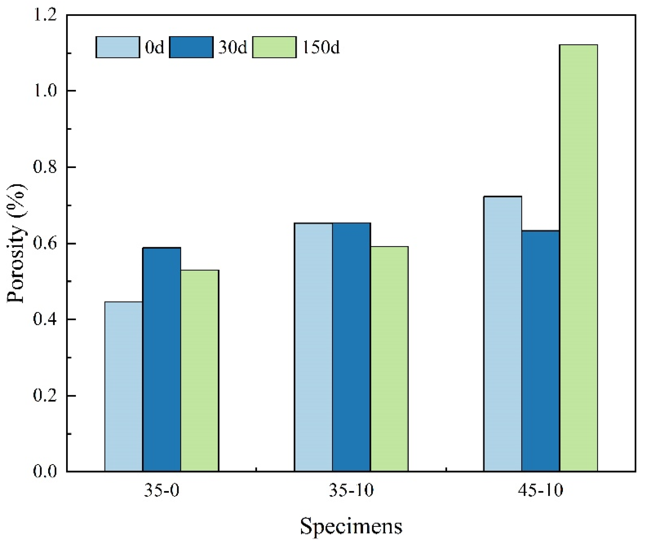
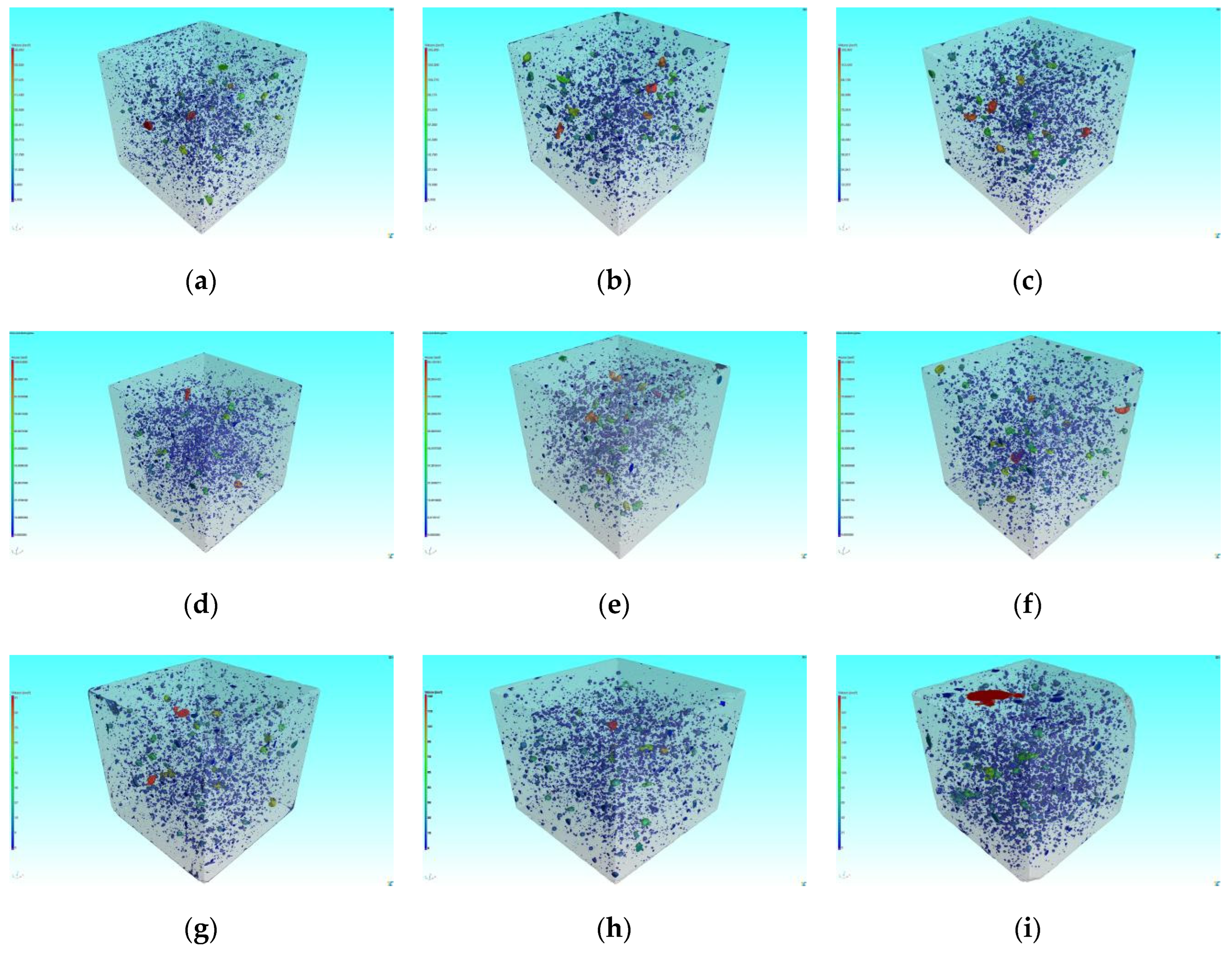
A 3D pore feature model was built by the VGStudio superimposition algorithm to visualize the real morphology of the pores, which facilitated the evaluation of the morphological changes of the pores. In order to evaluate the overall porosity in the specimen, 3D pore characteristics were calculated and the results were shown in
Figure 8 and
Figure 9.
It can be seen from
Figure 8 that the porosity of the specimens without MWCNT grew with the number of sulfate dry-wet cycles, as shown by an increase of 31.84% and 18.83% after 30 and 150 sulfate dry-wet cycles, respectively. After 150 sulfate dry-wet cycles, the porosity of specimen 35-10 decreased by 9.34%, while the porosity of specimen 45-10 increased by 55.19%. The 3D pore characterization results further confirmed the inhibitory effect of MWCNTs and low W/C on pore deterioration under sulfate dry-wet cycling. This is similar to the result of 2D pore analysis.
Figure 8.
The porosity of 35-0, 35-10 and 45-10 based on CT.
Figure 8.
The porosity of 35-0, 35-10 and 45-10 based on CT.
Figure 9.
3D reconstruction pore structure comparison. (a) 35-0; (b) 35-10; (c) 45-10; (d) 35-0 30d; (e) 35-10 30d; (f) 45-10 30d; (g) 35-0 150d; (h) 35-10 150d; (i) 45-10 150d.
Figure 9.
3D reconstruction pore structure comparison. (a) 35-0; (b) 35-10; (c) 45-10; (d) 35-0 30d; (e) 35-10 30d; (f) 45-10 30d; (g) 35-0 150d; (h) 35-10 150d; (i) 45-10 150d.
3.5.3. Frequency Distribution of Pore Size
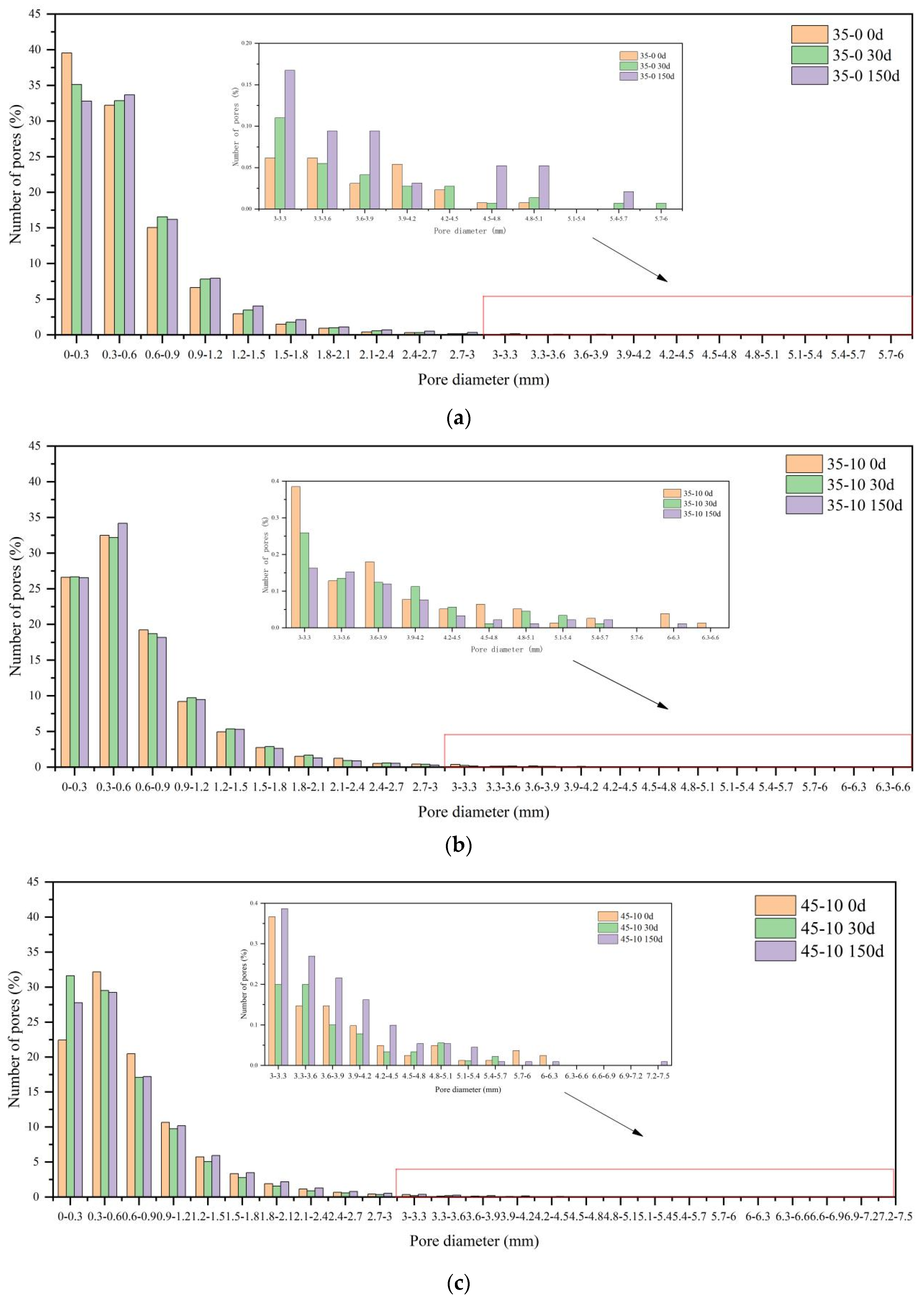
The characterizations of pore size and distribution were more complicated. In this section, the pore sizes were graded from 0 based on the statistical results. The percentage of pore diameter after different number of sulfate dry-wet cycles were shown in
Figure 8 and
Table 6.
Table 6.
Comparison of pore size distribution (%).
Table 6.
Comparison of pore size distribution (%).
| No. |
Time (days) |
Proportion of aperture distribution (%) |
| d < 1 mm |
1 mm ≤ d < 3 mm |
3 mm ≤ d < 5 mm |
d ≥ 5 mm |
| 35-0 |
0 |
89.48 |
10.27 |
0.25 |
0 |
| 30 |
87.91 |
11.79 |
0.28 |
0.02 |
| 150 |
85.79 |
13.70 |
0.49 |
0.02 |
| 35-10 |
0 |
81.99 |
16.99 |
0.92 |
0.10 |
| 30 |
81.73 |
17.48 |
0.73 |
0.06 |
| 150 |
82.82 |
16.55 |
0.58 |
0.05 |
| 45-10 |
0 |
79.42 |
19.62 |
0.87 |
0.09 |
| 30 |
82.18 |
17.09 |
0.70 |
0.03 |
| 150 |
78.18 |
20.50 |
1.23 |
0.09 |
Figure 10.
Pore diameter distribution of (a) 35-0; (b) 35-10; (c) 45-10.
Figure 10.
Pore diameter distribution of (a) 35-0; (b) 35-10; (c) 45-10.
As shown in
Figure 10, when the 35-0 specimens were not eroded, the pore size ranged from 0 to 0.3 mm. As the number of sulfate dry-wet cycling increases, the percentage of pores in the range of 0~0.3 mm decreases, while the percentage of pores larger than 0.3 mm increases. It was observed that after 30 sulfate dry-wet cycles, the percentage of 0~3 mm pores in specimen 35-0 was 11.18% lower relative to uncorroded. After 150 sulfate dry-wet cycles, most of the pores in the specimens were 0.3~0.6 mm and the proportion of pores larger than 0.9 mm increases. In addition, there was no evidence of the existence of the 5.4~5.7 mm and 5.7~6 mm pores prior to erosion. Bigger pores were formed under sulfate dry-wet cycling, resulting in the destruction of the pore structure. When the specimen 35-10 was not eroded, the majority of the pore sizes were in the range of 0.3-0.6 mm. As the number of sulfate dry-wet cycling increases, the proportion of the 0~0.3 mm pores did not vary. The content of the 0.3-0.6 mm pores decreased by 0.94% after 30 sulfate dry-wet cycles while expanding by 5.17% after 150 sulfate dry-wet cycles. The percentage of pore sizes larger than 6 mm dropped. The fraction of small pores barely changed, whereas the proportion of large pores decreased, revealing that the MWCNTs effectively attenuate the degradation of pores. Most pores in the specimen 45-10 were between 0.3 mm and 0.6 mm in size. Nevertheless, after 30 and 150 sulfate dry-wet cycles, the number of pores in this range decreased by 8.27% while the fraction of pores between 0 and 0.3 mm increased. The percentage of pores of 5.4-5.7 mm, 5.7-6 mm and 6-6.3 mm were reduced by 26.55%, 75.51% and 63.26%, respectively. It can be evident that higher W/C after 150 sulfate dry-wet cycles appeared larger pores, and the addition of MWCNTs served to further optimize the internal pore structure of the concrete, making it denser inside.
3.5.4. Compactness and Sphericity
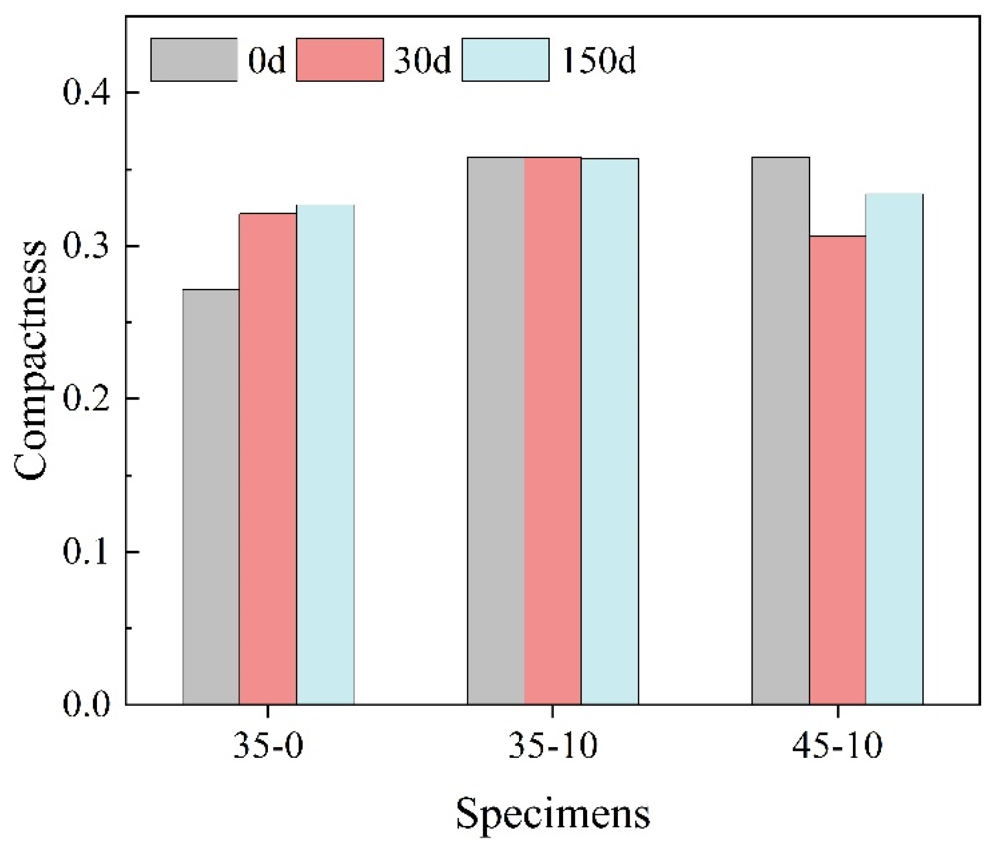
The development of the 3D model of the pores enables the visualization of the true form of the pores, and the true shape of the pores can be described using two 3D metrics: compactness and sphericity. The specific calculation is based on Equation (3) and Equation (4). The results are shown in
Figure 11 and
Figure 12.
where
Vdefect is three-dimensional pore volume, V
sphere is external sphere volume.
where
V is three-dimensional pore volume, A is three-dimensional pore surface area.
The compactness and sphericity were used to measure the regularity of the pores. The closer the two values are to one, the greater the resemblance of the pore with a regular circle. According to
Figure 11, the average compactness of the specimens without MWCNTs was lower than that of the specimens with MWCNTs, while The compactness of the specimen decreases with the increase of W/C This indicated that the specimens with MWCNTs and low W/C exhibited better pore characteristics.
Figure 12 showed that the frequency increases as the sphericity increases, while it decreases with increasing sphericity after the sphericity reached approximately 0.6. The sphericity of most pores was between 0.4 and 0.7, only that of a few pores was above 0.8 which suggested that the closer the range of standard circles the smaller the number of pores. More than half of the specimens have a sphericity greater than 0.6, which demonstrated that most of the specimens have a pore form closer to the ideal sphere. Besides, it could be observed that the total frequency of specimen 35-10 exceeded 60% when the sphericity was between 0.4 and 0.7, which was on average 12.27% higher than that of specimens without MWCNTs, and 27.25%, 6.19%, and 5.11% higher after 0, 30, and 150 sulfate dry-wet cycles, respectively. This further showed that the addition of MWCNTs has a positive effect on pore structure optimization.
4. Conclusions
In this study, the mechanical and durability properties of multi-walled carbon nanotube-lithium slag concrete (MWCNTs-LSC) after sulfate dry-wet cycles were studied. Microstructure and pore structure were analyzed based on SEM and CT tests results. The main conclusions could be summarized as follow:
(1) MWCNTs significantly increased the compressive strength of LSC. The compressive strength increased and then decreased with the increase of MWCNTs content. The LSC compressive strength reached the maximum value of 71.3 MPa when the water-cement ratio was 0.35 and 0.10 wt% of MWCNTs. Compared with the specimens without MWCNTs, the compressive strength increased by 4.7%.
(2) A moderate amount of MWCNTs enhanced LSC resistance to sulfate attack after sulfate dry-wet cycles. After 150 sulfate dry-wet cycles, most of the MWCNTs-LSC specimens showed no significant changes in appearance. The compressive strength tended to increase and then decrease as the number of sulfate dry-wet cycling increased, but the mass loss rate tended to decrease and then increase.
(3) SEM test showed that MWCNTs improved the resistance of concrete to sulfate attack by filling pores and forming bridges in cracks within the concrete, hindering crack expansion.
(4) CT test showed that the addition of MWCNTs could effectively reduce the porosity. In addition, MWCNTs could optimize the pores and improve the sphericity and compactness.
(5) The above conclusion provides references for further research on MWCNTs-LSC and its potential applications in construction. In addition, it should be noted that more in-depth and refined studies on MWCNTs-LSC exposed to different aggressive environments are required in the future.
Author Contributions
Conceptualization, Y.Z. and Y.Q.; methodology, Y.Z.; software, Y.Z. and Z.G.; validation, Y.Z. and Z.G.; formal analysis, Y.Z. and D.L.; investigation, D.L.; resources, Y.Q.; data curation, Y.Z. and Y.Q.; writing—original draft preparation, Y.Z.; writing—review and editing, Y.Z. and Z.G; visualization, Y.Z.; supervision, Y.Q.; project administration, Y.Q.; funding acquisition, Y.Q. All authors have read and agreed to the published version of the manuscript.
Funding
This research was funded by the National Natural Science Foundation of China, grant number 51668061 and Xinjiang Uygur Autonomous Region Science and Technology Support Project, grant number 2022E02022.
Institutional Review Board Statement
Not applicable.
Informed Consent Statement
Not applicable.
Data Availability Statement
The data used in the article can be obtained from the author here.
Acknowledgments
This work reported here was conducted with the financial supports from the National Natural Science Foundation of China (Grant No. 51668061), the Science & Technology Department of Xinjiang Uyghur Autonomous Region (Grant No. 2022E02022). The supports are gratefully acknowledged. The work of Mr. Tao Wang and Mr. Xiangjing Lu for the resources provided in the experimental tests are also gratefully acknowledged.
Conflicts of Interest
The authors declare no conflict of interest.
References
- Cefis, N.; Comi, C. Chemo-Mechanical Modelling of the External Sulfate Attack in Concrete. Cem. Concr. Res. 2017, 93, 57–70. [Google Scholar] [CrossRef]
- Cheng, H.; Liu, T.; Zou, D.; Zhou, A. Compressive Strength Assessment of Sulfate-Attacked Concrete by Using Sulfate Ions Distributions. Constr. Build. Mater. 2021, 293, 123550. [Google Scholar] [CrossRef]
- Zhang, C.; Chen, W.; Mu, S.; Savija, B.; Liu, Q. Numerical Investigation of External Sulfate Attack and Its Effect on Chloride Binding and Diffusion in Concrete. Constr. Build. Mater. 2021, 285, 122806. [Google Scholar] [CrossRef]
- Wongprachum, W.; Sappakittipakorn, M.; Sukontasukkul, P.; Chindaprasirt, P.; Banthia, N. Resistance to Sulfate Attack and Underwater Abrasion of Fiber Reinforced Cement Mortar. Constr. Build. Mater. 2018, 189, 686–694. [Google Scholar] [CrossRef]
- Zhao, G.; Guo, M.; Cui, J.; Li, J.; Xu, L. Partially-Exposed Cast-in-Situ Concrete Degradation Induced by Internal-External Sulfate and Magnesium Multiple Coupled Attack. Constr. Build. Mater. 2021, 294, 123560. [Google Scholar] [CrossRef]
- Haufe, J.; Vollpracht, A. Tensile Strength of Concrete Exposed to Sulfate Attack. Cem. Concr. Res. 2019, 116, 81–88. [Google Scholar] [CrossRef]
- Spragg, R.P.; Castro, J.; Li, W.; Pour-Ghaz, M.; Huang, P.-T.; Weiss, J. Wetting and Drying of Concrete Using Aqueous Solutions Containing Deicing Salts. Cem. Concr. Compos. 2011, 33, 535–542. [Google Scholar] [CrossRef]
- Feng, P.; Garboczi, E.J.; Miao, C.; Bullard, J.W. Microstructural Origins of Cement Paste Degradation by External Sulfate Attack. Constr. Build. Mater. 2015, 96, 391–403. [Google Scholar] [CrossRef]
- Irassar, E.F.; Maio, A.D.; Batic, O.R. Sulfate Attack on Concrete with Mineral Admixtures. Cement and Concrete Research 1996, 26, 113–123. [Google Scholar] [CrossRef]
- Aköz, F.; Türker, F.; Koral, S.; Yüzer, N. Effects of Sodium Sulfate Concentration on the Sulfate Resistance of Mortars with and without Silica Fume. Cement and Concrete Research 1995, 25, 1360–1368. [Google Scholar] [CrossRef]
- Santhanam, M.; Cohen, M.D.; Olek, J. Mechanism of Sulfate Attack: A Fresh Look Part 1: Summary of Experimental Results. Cem. Concr. Res. 2002, 32, 915–921. [Google Scholar] [CrossRef]
- Aggarwal, P.; Singh, R.P.; Aggarwal, Y.; Hussain, R.R. Use of Nano-Silica in Cement Based Materials—A Review. Cogent Engineering 2015, 1078018. [Google Scholar] [CrossRef]
- Paul, S.C.; van Rooyen, A.S.; van Zijl, G.P.A.G.; Petrik, L.F. Properties of Cement-Based Composites Using Nanoparticles: A Comprehensive Review. Constr. Build. Mater. 2018, 189, 1019–1034. [Google Scholar] [CrossRef]
- Liu, X.; Chen, L.; Liu, A.; Wang, X. Effect of Nano-CaCO3 on Properties of Cement Paste. Energy Procedia 2012, 16, 991–996. [Google Scholar] [CrossRef]
- Iijima, S. Helical Microtubules of Graphitic Carbon. Nature 1991, 354, 56–58. [Google Scholar] [CrossRef]
- Yu, M.-F.; Lourie, O.; Dyer, M.J.; Moloni, K.; Kelly, T.F.; Ruoff, R.S. Strength and Breaking Mechanism of Multiwalled Carbon Nanotubes Under Tensile Load. Science 2000, 287, 637–640. [Google Scholar] [CrossRef]
- Tyson, B.M.; Abu Al-Rub, R.K.; Yazdanbakhsh, A.; Grasley, Z. Carbon Nanotubes and Carbon Nanofibers for Enhancing the Mechanical Properties of Nanocomposite Cementitious Materials. J. Mater. Civ. Eng. 2011, 23, 1028–1035. [Google Scholar] [CrossRef]
- Han, B.; Sun, S.; Ding, S.; Zhang, L.; Yu, X.; Ou, J. Review of Nanocarbon-Engineered Multifunctional Cementitious Composites. Composites Part A: Applied Science and Manufacturing 2015, 70, 69–81. [Google Scholar] [CrossRef]
- Huang, J.Y.; Chen, S.; Wang, Z.Q.; Kempa, K.; Wang, Y.M.; Jo, S.H.; Chen, G.; Dresselhaus, M.S.; Ren, Z.F. Superplastic Carbon Nanotubes. Nature 2006, 439, 281–281. [Google Scholar] [CrossRef]
- Liew, K.M.; Kai, M.F.; Zhang, L.W. Carbon Nanotube Reinforced Cementitious Composites: An Overview. Composites Part A: Applied Science and Manufacturing 2016, 91, 301–323. [Google Scholar] [CrossRef]
- Makar, J.M.; Chan, G.W. Growth of Cement Hydration Products on Single-Walled Carbon Nanotubes. J. Am. Ceram. Soc. 2009, 92, 1303–1310. [Google Scholar] [CrossRef]
- Azhari, F.; Banthia, N. Cement-Based Sensors with Carbon Fibers and Carbon Nanotubes for Piezoresistive Sensing. Cem. Concr. Compos. 2012, 34, 866–873. [Google Scholar] [CrossRef]
- Moore, V.C.; Strano, M.S.; Haroz, E.H.; Hauge, R.H.; Smalley, R.E.; Schmidt, J.; Talmon, Y. Individually Suspended Single-Walled Carbon Nanotubes in Various Surfactants. Nano Lett. 2003, 3, 1379–1382. [Google Scholar] [CrossRef]
- Gao, F.; Tian, W.; Wang, Z.; Wang, F. Effect of Diameter of Multi-Walled Carbon Nanotubes on Mechanical Properties and Microstructure of the Cement-Based Materials. Constr. Build. Mater. 2020, 260, 120452. [Google Scholar] [CrossRef]
- Konsta-Gdoutos, M.S.; Metaxa, Z.S.; Shah, S.P. Highly Dispersed Carbon Nanotube Reinforced Cement Based Materials. Cem. Concr. Res. 2010, 40, 1052–1059. [Google Scholar] [CrossRef]
- Li, W.-W.; Ji, W.-M.; Wang, Y.-C.; Liu, Y.; Shen, R.-X.; Xing, F. Investigation on the Mechanical Properties of a Cement-Based Material Containing Carbon Nanotube under Drying and Freeze-Thaw Conditions. Materials 2015, 8, 8780–8792. [Google Scholar] [CrossRef]
- Xu, S.; Liu, J.; Li, Q. Mechanical Properties and Microstructure of Multi-Walled Carbon Nanotube-Reinforced Cement Paste. Constr. Build. Mater. 2015, 76, 16–23. [Google Scholar] [CrossRef]
- Nochaiya, T.; Chaipanich, A. Behavior of Multi-Walled Carbon Nanotubes on the Porosity and Microstructure of Cement-Based Materials. Appl. Surf. Sci. 2011, 257, 1941–1945. [Google Scholar] [CrossRef]
- Kim, H.-K. Chloride Penetration Monitoring in Reinforced Concrete Structure Using Carbon Nanotube/Cement Composite. Construction and Building Materials 2015, 96, 29–36. [Google Scholar] [CrossRef]
- Wang, J.; Bai, X.; Zhao, J.; Gao, Z. Carbon Nanotubes Enhance RPC Bending Fatigue Performanc. Journal of Building Materials 2020, 23, 1345–1349. [Google Scholar]
- Liu, G.; Zhang, H.; Liu, J.; Xu, S.; Chen, Z. Experimental Study on the Salt Freezing Durability of Multi-Walled Carbon Nanotube Ultra-High-Performance Concrete. Materials 2022, 15, 3188. [Google Scholar] [CrossRef] [PubMed]
- Páez-Pavón, A.; García-Junceda, A.; Galán-Salazar, A.; Merodio-Perea, R.G.; Sánchez del Río, J.; Lado-Touriño, I. Microstructure and Electrical Conductivity of Cement Paste Reinforced with Different Types of Carbon Nanotubes. Materials 2022, 15, 7976. [Google Scholar] [CrossRef] [PubMed]
- MacLeod, A.J.N.; Gates, W.P.; Collins, F. Durability Characterisation of Portland Cement–Carbon Nanotube Nanocomposites. Materials 2020, 13, 4097. [Google Scholar] [CrossRef] [PubMed]
- Hawreen, A.; Bogas, J.A.; Dias, A.P.S. On the Mechanical and Shrinkage Behavior of Cement Mortars Reinforced with Carbon Nanotubes. Construction and Building Materials 2018, 168, 459–470. [Google Scholar] [CrossRef]
- Luo, J.; Hou, D.; Li, Q.; Wu, C.; Zhang, C. Comprehensive Performances of Carbon Nanotube Reinforced Foam Concrete with Tetraethyl Orthosilicate Impregnation. Construction and Building Materials 2017, 131, 512–516. [Google Scholar] [CrossRef]
- Hu, Y.; Luo, D.; Li, P.; Li, Q.; Sun, G. Fracture Toughness Enhancement of Cement Paste with Multi-Walled Carbon Nanotubes. Constr. Build. Mater. 2014, 70, 332–338. [Google Scholar] [CrossRef]
- Liu, G.; Kan, D.; Cao, S.C.; Chen, Z.; Lyu, Q. Effect of Multi-Walled Carbon Nanotube on Reactive Powder Concrete (RPC) Performance in Sulfate Dry-Wet Cycling Environment. Constr. Build. Mater. 2022, 342, 128075. [Google Scholar] [CrossRef]
- Ministry of Housing and Urban-Rural Construction of the People’s Republic of China. Standard for Test Methods of Performance (GB/T50080-2016). China Construction Industry Press: Beijing, 2016. [Google Scholar]
- Ministry of Housing and Urban-Rural Construction of the People’s Republic of China. Standard for Test Methods of Long-term Performance and Durability of Ordinary Concrete (GB/T50082-2009). China Construction Industry Press: Beijing, 2009. [Google Scholar]
- Ministry of Housing and Urban-Rural Construction of the People’s Republic of China. Standard for Test Methods of Physical and Mechanical Properties of Concrete (GB/T50081-2019). China Construction Industry Press: Beijing, 2019. [Google Scholar]
- Fu, J.; Yu, Y. Experimental Study on Pore Characteristics and Fractal Dimension Calculation of Pore Structure of Aerated Concrete Block. Adv. Civ. Eng. 2019, 2019, 8043248. [Google Scholar] [CrossRef]
|
Disclaimer/Publisher’s Note: The statements, opinions and data contained in all publications are solely those of the individual author(s) and contributor(s) and not of MDPI and/or the editor(s). MDPI and/or the editor(s) disclaim responsibility for any injury to people or property resulting from any ideas, methods, instructions or products referred to in the content. |
© 2023 by the authors. Licensee MDPI, Basel, Switzerland. This article is an open access article distributed under the terms and conditions of the Creative Commons Attribution (CC BY) license (http://creativecommons.org/licenses/by/4.0/).
