Submitted:
27 April 2023
Posted:
28 April 2023
You are already at the latest version
Abstract
Keywords:
1. Introduction
2. Experiment Section
2.1. Material Preparations
2.2. Characterization Methods
3. Results and Discussion
4. Conclusions
Supplementary Materials
Acknowledgments
Conflicts of Interest
References
- De Jeu, W.H. Liquid Crystal Elastomers: Materials and Applications; Aachen University: Aachen, Germany,, 2012. [Google Scholar]
- Pilz da Cunha, M.; Debije, M.G.; Schenning, A.P. H. J. Bioinspired light-driven soft robots based on liquid crystal polymers. Chem. Soc. Rev. 2020, 49, 6568–6578. [Google Scholar] [CrossRef] [PubMed]
- Wang, Q.E.; Niu, H.; Wang, Y.; Li, C. Carbon nanotubes modified nanocomposites based on liquid crystalline elastomers. Mol. Cryst. Liq. Cryst. 2021, 732, 11–49. [Google Scholar] [CrossRef]
- Schwartz, M.; Lagerwall, J. P. F. Embedding intelligence in materials for responsive built environment: A topical review on Liquid Crystal Elastomer actuators and sensors. Build. Environ. 2022, 226, 109714. [Google Scholar] [CrossRef]
- Wang, Y.C.; Liu, J.Q.; Yang, S. Multi-functional liquid crystal elastomer composites. Appl. Phys. Rev. 2022, 9, 011301. [Google Scholar] [CrossRef]
- Zhang, W.; Nan, Y. F.; Wu, Z. X.; Shen, Y.J.; Luo, D. Photothermal-Driven Liquid Crystal Elastomers: Materials, Alignment and Applications. Molecules 2022, 27, 4330. [Google Scholar] [CrossRef] [PubMed]
- Liu, L.; Wang, M.; Guo, L.-X.; Sun, Y.; Zhang, X.-Q.; Lin, B.-P.; Yang, H. Aggregation-Induced Emission Luminogen-Functionalized Liquid Crystal Elastomer Soft Actuators. Macromolecules 2018, 51, 4516–4524. [Google Scholar] [CrossRef]
- Saed, M.O.; Ambulo, C.P.; Kim, H.; De, R.; Raval, V.; Searles, K.; Siddiqui, D.A.; Cue, J.M. O.; Stefan, M.C.; Shankar, M.R.; Ware, T.H. Molecularly-Engineered, 4D-Printed Liquid Crystal Elastomer Actuators. Adv. Funct. Mater. 2019, 29, 1806412. [Google Scholar] [CrossRef]
- Chen, Q.; Li, Y.; Yang, Y.; Xu, Y.; Qian, X.; Wei, Y.; Ji, Y. Durable liquid-crystalline vitrimer actuators. Chem. Sci. 2019, 10, 3025–3030. [Google Scholar] [CrossRef]
- Zuo, B.; Wang, M.; Lin, B.P.; Yang, H. Visible and infrared three-wavelength modulated multi-directional actuators. Nat. Commun. 2019, 10, 4539. [Google Scholar] [CrossRef]
- He, Q.; Wang, Z.; Wang, Y.; Song, Z.; Cai, S. Recyclable and Self-Repairable Fluid-Driven Liquid Crystal Elastomer Actuator. ACS Appl. Mater. Interfaces 2020, 12, 35464–35474. [Google Scholar] [CrossRef]
- Li, Y.; Liu, Y.; Luo, D. Polarization Dependent Light-Driven Liquid Crystal Elastomer Actuators Based on Photothermal Effect. Adv. Opt. Mater. 2020, 9, 2001861.1–2001861.9. [Google Scholar] [CrossRef]
- Xu, J.; Zhao, N.; Qin, B.; Qu, M.; Wang, X.; Ridi, B.; Li, C.; Gao, Y. Optical Wavelength Selective Photoactuation of Nanometal-Doped Liquid Crystalline Elastomers by Using Surface Plasmon Resonance. ACS Appl. Mater. Interfaces 2021, 13, 44833–44843. [Google Scholar] [CrossRef] [PubMed]
- Yao, L.R.; Yan, H.X.; He, Y.F.; Zhao, N.; Wang, X.X.; Li, C.S.; Sun, L.G.; He, Y.; Liu, Y.J.; Zhang, J.Q. Actuation performances of catkin fibers reinforced thiol-acrylate main-chain liquid crystalline elastomer. Int. J. Smart Nano Mat. 2022, 13, 668–690. [Google Scholar] [CrossRef]
- Zhang, X.Y.; Yao, L. R.; Yan, H. X.; Zhang, Y. H.; Han, D. X.; He, Y. F.; Li, C. S.; Zhang, J. Q. Optical wavelength selective actuation of dye doped liquid crystalline elastomers by quasi-daylight. Soft Matter 2022, 18, 9181–9196. [Google Scholar] [CrossRef] [PubMed]
- Zhao, T.; Zhang, Y.; Fan, Y.; Wang, J.; Jiang, H.; Lv, J.-A. Light-modulated liquid crystal elastomer actuator with multimodal shape morphing and multifunction. J. Mater. Chem. C. 2022, 10, 3796–3803. [Google Scholar] [CrossRef]
- Qian, X.; Chen, Q.; Yang, Y.; Xu, Y.; Li, Z.; Wang, Z.; Wu, Y.; Wei, Y.; Ji, Y. Untethered Recyclable Tubular Actuators with Versatile Locomotion for Soft Continuum Robots. Adv. Mater. 2018, 30, 1801103. [Google Scholar] [CrossRef] [PubMed]
- Zeng, H.; Wasylczyk, P.; Wiersma, D.S.; Priimagi, A. Light Robots: Bridging the Gap between Microrobotics and Photomechanics in Soft Materials. Adv. Mater. 2018, 30, 1703554. [Google Scholar] [CrossRef]
- He, Q. G.; Wang, Z. J.; Wang, Y.; Minori, A.; Tolley, M.T.; Cai, S. Q. Electrically controlled liquid crystal elastomer-based soft tubular actuator with multimodal actuation. Sci. Adv. 2019, 5, eaax5746. [Google Scholar] [CrossRef]
- Shen, C.; Lan, R.; Huang, R.; Zhang, Z.; Bao, J.; Zhang, L.; Yang, H. Photochemically and Photothermally Controllable Liquid Crystalline Network and Soft Walkers. ACS App. Mater. Interfaces 2021, 13, 3221–3227. [Google Scholar] [CrossRef]
- Li, Y.; Yu, H.B.; Yu, K.; Guo, X.G.; Wang, X.J. Reconfigurable Three-Dimensional Mesotructures of Spatially Programmed Liquid Crystal Elastomers and Their Ferromagnetic Composites. Adv. Funct. Mater. 2021, 31, 2100338. [Google Scholar] [CrossRef]
- Zhang, J.; Guo, Y.; Hu, W.; Soon, R.H.; Davidson, Z.S.; Sitti, M. Liquid Crystal Elastomer-Based Magnetic Composite Films for Reconfigurable Shape-Morphing Soft Miniature Machines. Adv. Mater. 2021, 33, 2006191. [Google Scholar] [CrossRef] [PubMed]
- Apsite, I.; Salehi, S.; Ionov, L. Materials for Smart Soft Actuator Systems. Chem. Rev. 2022, 122, 1349–1415. [Google Scholar] [CrossRef] [PubMed]
- Yu, Z.; Wang, Y.; Zheng, J.; Sun, S.; Fu, Y.; Chen, D.; Cai, W.; Wang, D.; Zhou, H.; Li, D. Fast-Response Bioinspired Near-Infrared Light-Driven Soft Robot Based on Two-Stage Deformation. ACS Appl. Mater. Interfaces 2022, 14, 16649–16657. [Google Scholar] [CrossRef] [PubMed]
- Tian, H.; Wang, Z.; Chen, Y.; Shao, J.; Gao, T.; Cai, S. Polydopamine-Coated Main-Chain Liquid Crystal Elastomer as Optically Driven Artificial Muscle. ACS Appl. Mater. Interfaces 2018, 10, 8307–8316. [Google Scholar] [CrossRef]
- Kim, H.; Lee, J.A.; Ambulo, C.P.; Lee, H.B.; Kim, S.H.; Naik, V.V.; Haines, C.S.; Aliev, A.E.; Ovalle-Robles, R.; Baughman, R.H.; Ware, T.H. Intelligently Actuating Liquid Crystal Elastomer-Carbon Nanotube Composites. Adv. Funct. Mater. 2019, 29, 1905063. [Google Scholar] [CrossRef]
- Lu, H.-F.; Wang, M.; Chen, X.-M.; Lin, B.-P.; Yang, H. Interpenetrating Liquid-Crystal Polyurethane/Polyacrylate Elastomer with Ultrastrong Mechanical Property. J. Am. Chem. Soc. 2019, 141, 14364–14369. [Google Scholar] [CrossRef] [PubMed]
- Roach, D.J.; Yuan, C.; Kuang, X.; Li, V.C.-F.; Blake, P.; Romero, M.L.; Hammel, I.; Yu, K.; Qi, H.J. Long Liquid Crystal Elastomer Fibers with Large Reversible Actuation Strains for Smart Textiles and Artificial Muscles. ACS Appl. Mater. Interfaces 2019, 11, 19514–19521. [Google Scholar] [CrossRef]
- Liu, H.; Tian, H.; Shao, J.; Wang, Z.; Li, X.; Wang, C.; Chen, X. An Electrically Actuated Soft Artificial Muscle Based on a High-Performance Flexible Electrothermal Film and Liquid-Crystal Elastomer. ACS Appl. Mater. Interfaces 2020, 12, 56338–56349. [Google Scholar] [CrossRef]
- Chen, C.; Liu, Y.; He, X.; Li, H.; Chen, Y.; Wei, Y.; Zhao, Y.; Ma, Y.; Chen, Z.; Zheng, X.; Liu, H. Multiresponse Shape-Memory Nanocomposite with a Reversible Cycle for Powerful Artificial Muscles. Chem. Mater. 2021, 33, 987–997. [Google Scholar] [CrossRef]
- Lee, J.H.; Bae, J.; Hwang, J.H.; Choi, M.Y.; Kim, Y.S.; Park, S.; Na, J.H.; Kim, D.G.; Ahn, S.K. Robust and Reprocessable Artificial Muscles Based on Liquid Crystal Elastomers with Dynamic Thiourea Bonds. Adv. Funct. Mater. 2022, 32, 2110360. [Google Scholar] [CrossRef]
- Zhao, N.; Wang, X.; Yao, L.; Yan, H.; Qin, B.; Li, C.; Zhang, J. Actuation performance of a liquid crystalline elastomer composite reinforced by eiderdown fibers. Soft Matter 2022, 18, 1264–1274. [Google Scholar] [CrossRef] [PubMed]
- Lv, J.A.; Liu, Y.Y.; Wei, J.; Chen, E.Q.; Qin, L.; Yu, Y.L. Photocontrol of fluid slugs in liquid crystal polymer microactuators. Nature 2016, 537, 179. [Google Scholar] [CrossRef] [PubMed]
- Palagi, S.; Mark, A.G.; Reigh, S.Y.; Melde, K.; Qiu, T.; Zeng, H.; Parmeggiani, C.; Martella, D.; Sanchez-Castillo, A.; Kapernaum, N.; Giesselmann, F.; Wiersma, D.S.; Lauga, E.; Fischer, P. Structured light enables biomimetic swimming and versatile locomotion of photoresponsive soft microrobots. Nat. Mater. 2016, 15, 647. [Google Scholar] [CrossRef] [PubMed]
- Wang, M.; Lin, B.P.; Yang, H. A plant tendril mimic soft actuator with phototunable bending and chiral twisting motion modes. Nat. Commun. 2016, 7, 13981. [Google Scholar] [CrossRef] [PubMed]
- Shahsavan, H.; Salili, S.M.; Jakli, A.; Zhao, B. Thermally Active Liquid Crystal Network Gripper Mimicking the Self-Peeling of Gecko Toe Pads. Adv. Mater. 2017, 29, 1604021. [Google Scholar] [CrossRef] [PubMed]
- Zuo, B.; Wang, M.; Lin, B.-P.; Yang, H. Photomodulated Tricolor-Changing Artificial Flowers. Chem. Mater. 2018, 30, 8079–8088. [Google Scholar] [CrossRef]
- Ferrantini, C.; Pioner, J.M.; Martella, D.; Coppini, R.; Piroddi, N.; Paoli, P.; Calamai, M.; Pavone, F.S.; Wiersma, D.S.; Tesi, C.; Cerbai, E.; Poggesi, C.; Sacconi, L.; Parmeggiani, C. Development of Light-Responsive Liquid Crystalline Elastomers to Assist Cardiac Contraction. Circ. Res. 2019, 124, e44–e54. [Google Scholar] [CrossRef]
- Shaha, R.K.; Merkel, D.R.; Anderson, M.P.; Devereaux, E.J.; Patel, R.R.; Torbati, A.H.; Willett, N.; Yakacki, C.M.; Frick, C.P. Biocompatible liquid-crystal elastomers mimic the intervertebral disc. J. Mech. Behav. Biomed. Mater. 2020, 107, 103757. [Google Scholar] [CrossRef]
- Hussain, M.; Jull, E.I. L.; Mandle, R.J.; Raistrick, T.; Hine, P.J.; Gleeson, H.F. Liquid Crystal Elastomers for Biological Applications. Nanomaterials 2021, 11, 813. [Google Scholar] [CrossRef]
- Liu, Z.; Bisoyi, H.K.; Huang, Y.; Wang, M.; Yang, H.; Li, Q. Thermo- and Mechanochromic Camouflage and Self-Healing in Biomimetic Soft Actuators Based on Liquid Crystal Elastomers. Angew. Chem. Int. Ed. 2022, 61, e202115755. [Google Scholar] [CrossRef]
- Wang, Y.P.; Liao, W.; Sun, J.H.; Nandi, R.; Yang, Z.Q. Bioinspired Construction of Artificial Cardiac Muscles Based on Liquid Crystal Elastomer Fibers. Adv. Mater. Technol. 2022, 7, 2100934. [Google Scholar] [CrossRef]
- Wie, J.J.; Lee, K.; Smith, M.L.; Vaia, R.A.; White, T.J. Torsional mechanical responses in azobenzene functionalized liquid crystalline polymer networks. Soft Matter 2013, 9, 9303–9310. [Google Scholar] [CrossRef]
- Iamsaard, S.; Abhoff, S.J.; Matt, B.; Kudernac, T.; Cornelissen, J.L. M.; Fletcher, S.P.; Katsonis, N. Conversion of light into macroscopic helical motion. Nat. Chem. 2014, 6, 229–235. [Google Scholar] [CrossRef] [PubMed]
- Ware, T.H.; McConney, M.E.; Wie, J.J.; Tondiglia, V.P.; White, T.J. Voxelated liquid crystal elastomers. Science 2015, 347, 982–984. [Google Scholar] [CrossRef] [PubMed]
- Donovan, B.R.; Matavulj, V.M.; Ahn, S.-K.; Guin, T.; White, T.J. All-Optical Control of Shape. Adv. Mater. 2019, 31, 1805750. [Google Scholar] [CrossRef] [PubMed]
- Herbert, K.M.; Fowler, H.E.; McCracken, J.M.; Joselle, M.; Schlafmann, K.R.; Kyle, R.; Koch, J.A.; White, T.J. Synthesis and alignment of liquid crystalline elastomers. Nat. Rev. Mater. 2022, 7, 23–38. [Google Scholar] [CrossRef]
- Ohm, C.; Serra, C.; Zentel, R. A Continuous Flow Synthesis of Micrometer-Sized Actuators from Liquid Crystalline Elastomers. Adv. Mater. 2009, 21, 4859–4862. [Google Scholar] [CrossRef]
- Ohm, C.; Kapernaum, N.; Nonnenmacher, D.; Giesselmann, F.; Serra, C.; Zentel, R. Microfluidic Synthesis of Highly Shape-Anisotropic Particles from Liquid Crystalline Elastomers with Defined Director Field Configurations. J. Am. Chem. Soc. 2011, 133, 5305–5311. [Google Scholar] [CrossRef]
- Fleischmann, E.-K.; Liang, H.-L.; Kapernaum, N.; Giesselmann, F.; Lagerwall, J.; Zentel, R. One-piece micropumps from liquid crystalline core-shell particles. Nat. Commun. 2012, 3, 1178–1185. [Google Scholar] [CrossRef]
- Yaroshchuk, O.; Reznikov, Y. Photoalignment of liquid crystals: basics and current trends. J. Mater. Chem. 2012, 22, 286–300. [Google Scholar] [CrossRef]
- Ware, T.H.; Biggins, J.S.; Shick, A.F.; Warner, M.; White, T.J. Localized soft elasticity in liquid crystal elastomers. Nat. Commun. 2016, 7, 10781. [Google Scholar] [CrossRef] [PubMed]
- Zhao, J.Y.; Zhang, L.M.; Hu, J. Varied Alignment Methods and Versatile Actuations for Liquid Crystal Elastomers: A Review. Adv. Intell. Syst. 2022, 4, 2100065. [Google Scholar] [CrossRef]
- Buguin, A.; Li, M.-H.; Silberzan, P.; Ladoux, B.; Keller, P. Micro-actuators: when artificial muscles made of nematic liquid crystal elastomers meet soft lithography. J. Am. Chem. Soc. 2006, 128, 1088–1089. [Google Scholar] [CrossRef]
- Yang, H.; Buguin, A.; Taulemesse, J.-M.; Kaneko, K.; Mery, S.; Bergeret, A.; Keller, P. Micron-Sized Main-Chain Liquid Crystalline Elastomer Actuators with Ultralarge Amplitude Contractions. J. Am. Chem. Soc. 2009, 131, 15000–15004. [Google Scholar] [CrossRef] [PubMed]
- Cui, J.; Drotlef, D.M.; Larraza, I.; Ferna´ndez-Bla´zquez, J.P.; Boesel, L.F.; Ohm, C.; Mezger, M.; Zentel, R.; del Campo, A. Bioinspired Actuated Adhesive Patterns of Liquid Crystalline Elastomers. Adv. Mater. 2012, 24, 4601–4604. [Google Scholar] [CrossRef]
- Ambulo, C.; Burroughs, J.J.; Boothby, J.M.; Kim, H.; Shankar, M.R.; Ware, T.H. Four-dimensional Printing of Liquid Crystal Elastomers. ACS Appl. Mater. Interfaces 2017, 9, 37332–37339. [Google Scholar] [CrossRef] [PubMed]
- Lo´pez-Valdeolivas, M.; Liu, D.; Broer, D.J.; Sa´nchezSomolinos, C. 4D Printed Actuators with Soft-Robotic Functions. Macromol. Rapid Commun. 2018, 39, 1700710. [Google Scholar] [CrossRef] [PubMed]
- Kotikian, A.; Truby, R.L.; Boley, J.W.; White, T.J.; Lewis, J.A. 3D Printing of Liquid Crystal Elastomeric Actuators with Spatially Programed Nematic Order. Adv. Mater. 2018, 30, 1706164. [Google Scholar] [CrossRef]
- Wang, Z.J.; Guo, Y.B.; Cai, S.Q.; Yang, J.P. Three-Dimensional Printing of Liquid Crystal Elastomers and Their Applications. ACS Appl. Polym. Mater. 2022, 4, 3153–3168. [Google Scholar] [CrossRef]
- Wang, Y. P.; An, J.; Lee, H. Recent advances in molecular programming of liquid crystal elastomers with additive manufacturing for 4D printing. Mol. Syst. Des. Eng. 2022, 7, 1588–1601. [Google Scholar] [CrossRef]
- Pei, Z.; Yang, Y.; Chen, Q.; Terentjev, E.M.; Wei, Y.; Ji, Y. Mouldable liquid-crystalline elastomer actuators with exchangeable covalent bonds. Nat. Mater. 2014, 13, 36–41. [Google Scholar] [CrossRef] [PubMed]
- Pei, Z.; Yang, Y.; Chen, Q.; Wei, Y.; Ji, Y. Regional Shape Control of Strategically Assembled Multishape Memory Vitrimers. Adv. Mater. 2016, 28, 156–160. [Google Scholar] [CrossRef]
- McBride, M.K.; Hendrikx, M.; Liu, D.; Worrell, B.T.; Broer, D.J.; Bowman, C.N. Photoinduced Plasticity in Cross-Linked Liquid Crystalline Networks. Adv. Mater. 2017, 29, 1606509. [Google Scholar] [CrossRef] [PubMed]
- McBride, M.K.; Martinez, A.M.; Cox, L.; Alim, M.; Childress, K.; Beiswinger, M.; Podgorski, M.; Worrell, B.T.; Killgore, J.; Bowman, C.N. A readily programmable, fully reversible shape-switching material. Sci. Adv. 2018, 4, eaat4634. [Google Scholar] [CrossRef] [PubMed]
- Wang, Z.J.; He, Q.G.; Wang, Y.; Cai, S.Q. Programmable actuation of liquid crystal elastomers via ‘‘living’’ exchange reaction. Soft Matter 2019, 15, 2811–2816. [Google Scholar] [CrossRef] [PubMed]
- Jiang, Z.-C.; Xiao, Y.-Y.; Yin, L.; Han, L.; Zhao, Y. “Self-Lockable” Liquid Crystalline Diels–Alder Dynamic Network Actuators with Room Temperature Programmability and Solution Reprocessability. Angew. Chem. Int. Ed. 2020, 59, 4925–4931. [Google Scholar] [CrossRef] [PubMed]
- Valenzuela, C.; Chen, Y.H.; Wang, L.; Feng, W. Functional Liquid Crystal Elastomers Based on Dynamic Covalent Chemistry. Chem. Eur. J. 2022, 28, e202201957. [Google Scholar] [CrossRef]
- Kupfer, J.; Finkelmann, H. Nematic liquid single crystal elastomers. Macromol. Rapid Commun. 1991, 12, 717–726. [Google Scholar] [CrossRef]
- Wang, Y.C.; Huang, X.Z.; Zhang, J.Q.; Bi, M.; Zhang, J.D.; Niu, H.Y.; Li, C.S.; Yu, H.F.; Wang, B.S.; Jiang, H.R. Two-step crosslinked liquid-crystalline elastomer with reversible two-way shape memory characteristics. Mol. Cryst. Liq. Cryst. 2017, 650, 13–22. [Google Scholar] [CrossRef]
- Liu, Y.J.; Du, H.Y.; Liu, L.W.; Leng, J.S. Shape memory polymers and their composites in aerospace applications: a review. Smart. Mater. Struct. 2014, 23, 023001. [Google Scholar] [CrossRef]
- Yu, L.; Shahsavan, H.; Rivers, G.; Zhang, C.; Si, P.X.; Zhao, B.X. Programmable 3D Shape Changes in Liquid Crystal Polymer Networks of Uniaxial Orientation. Adv. Funct. Mater. 2018, 28, 1802809. [Google Scholar] [CrossRef]
- Barnes, M.; Verduzco, R. Direct shape programming of liquid crystal elastomers. Soft Matter 2019, 15, 870–879. [Google Scholar] [CrossRef] [PubMed]
- Lee, J.; Guo, Y.H.; Choi, Y.-J.; Jung, S.; Seol, D.; Choi, S.; Kim, J.-H.; Kim, Y.; Jeong, K.-U.; Ahn, S.-K. Mechanically programmed 2D and 3D liquid crystal elastomers at macro- and microscale via two-step photocrosslinking. Soft Matter 2020, 16, 2695–2705. [Google Scholar] [CrossRef] [PubMed]
- Wang, X.X.; Zhao, N.; Qin, B.; Xu, J.J.; Yang, W.L.; Li, C.S.; Sun, L.G.; Zhang, J.Q. Ultrasonics Sonochemistry Assisted Preparation of Polysiloxane Main-Chain Liquid-Crystalline Elastomers. Macromol. Chem. Phys. 2020, 221, 2000071. [Google Scholar] [CrossRef]
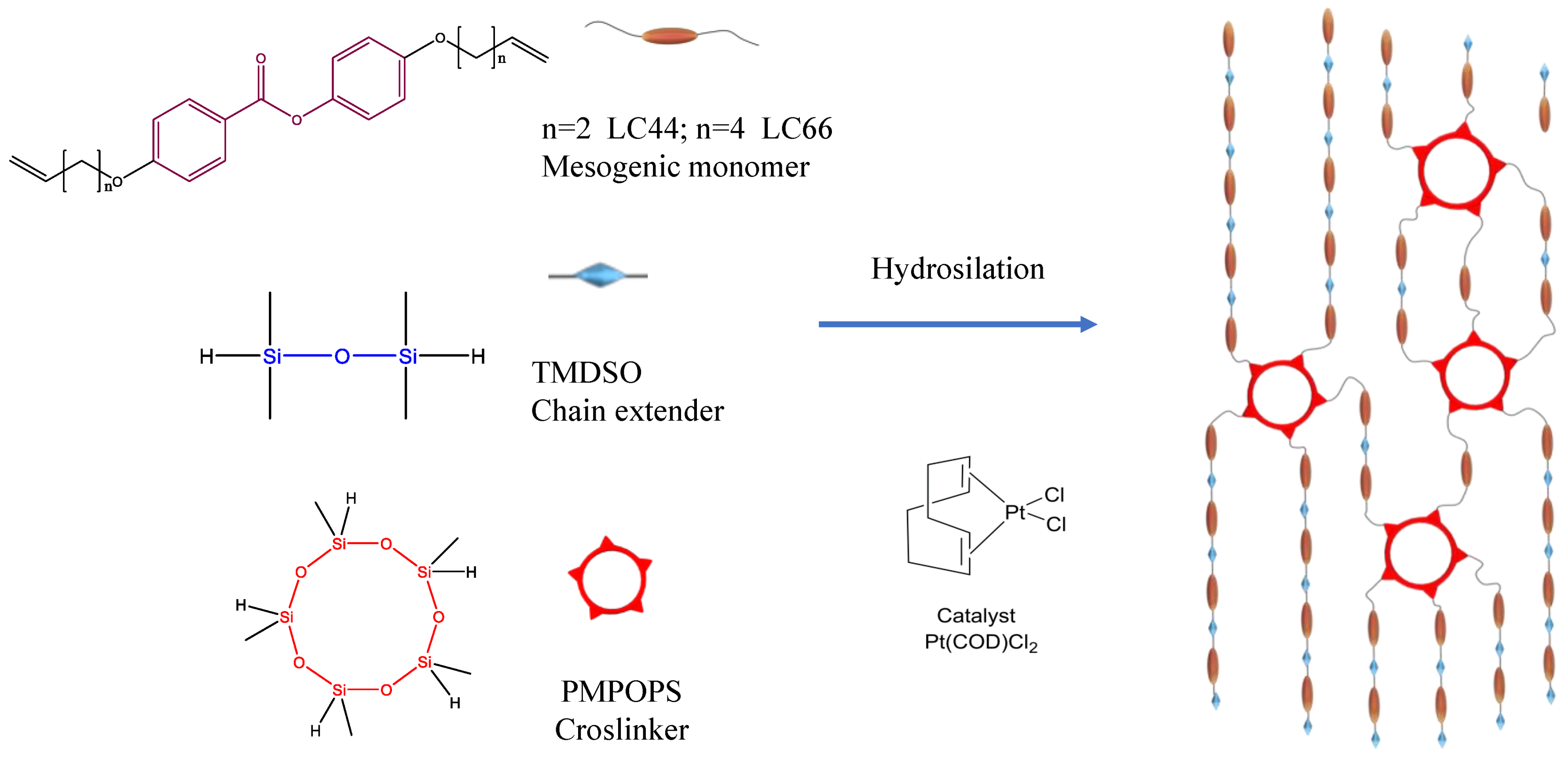
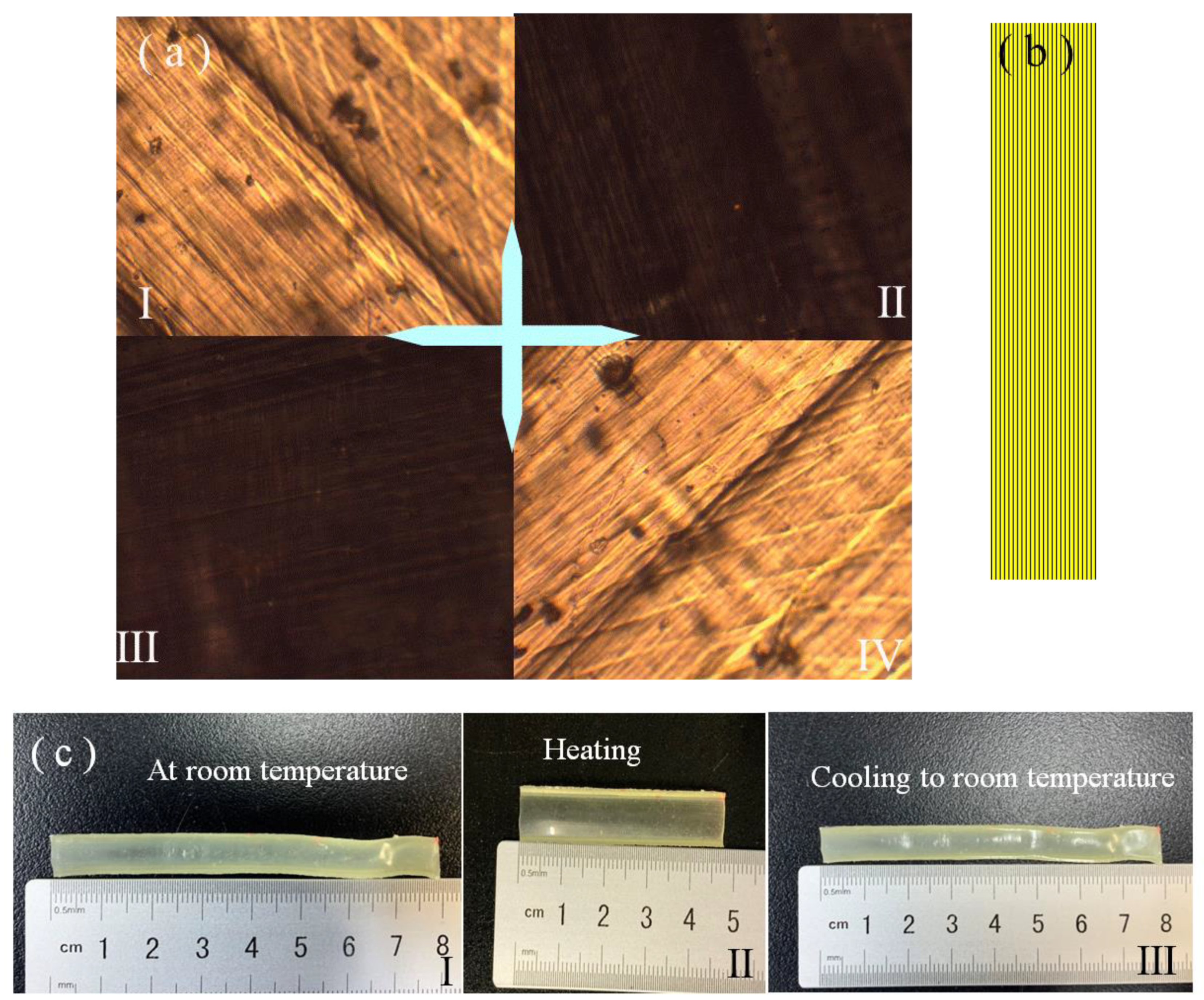
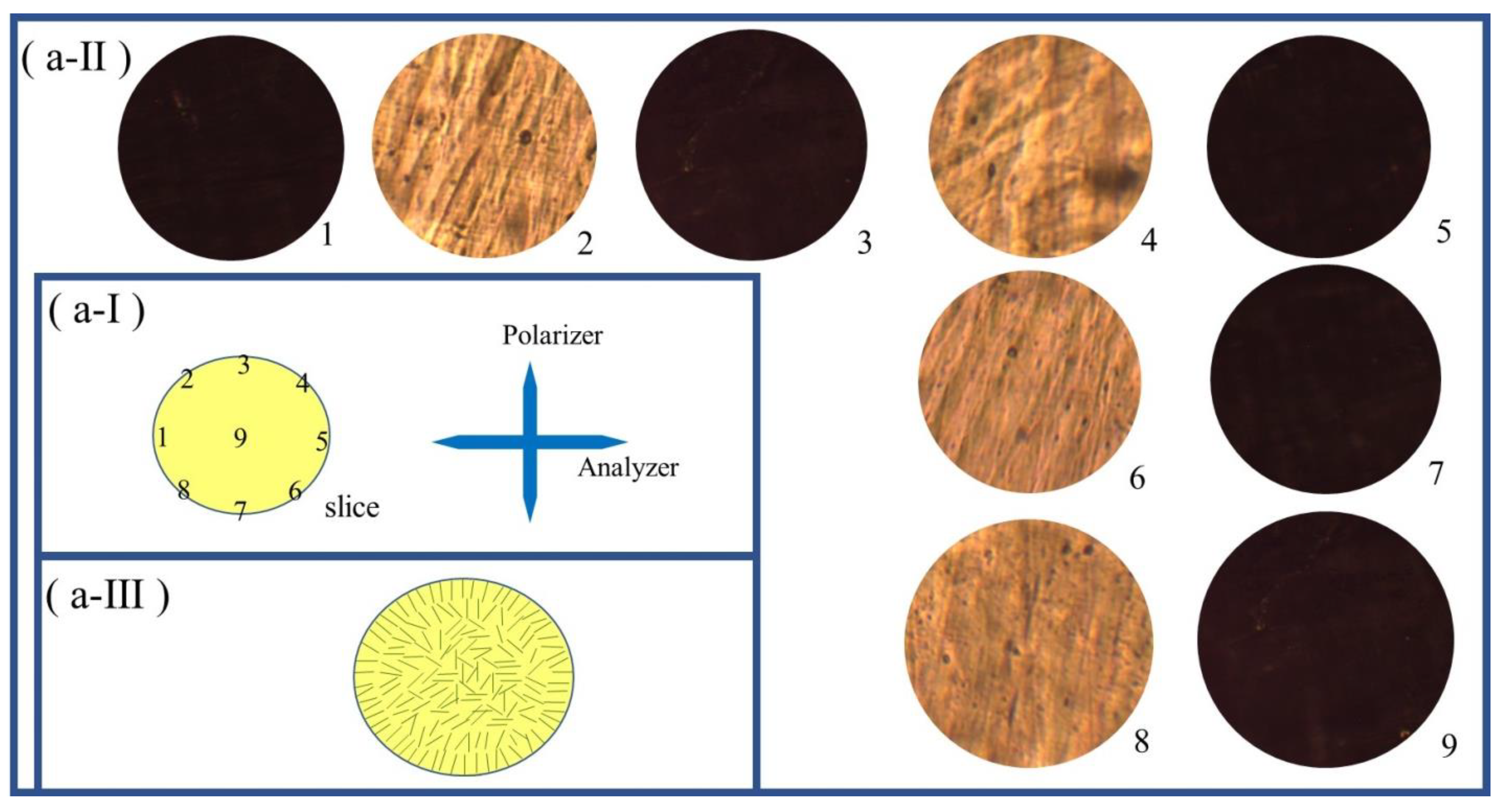


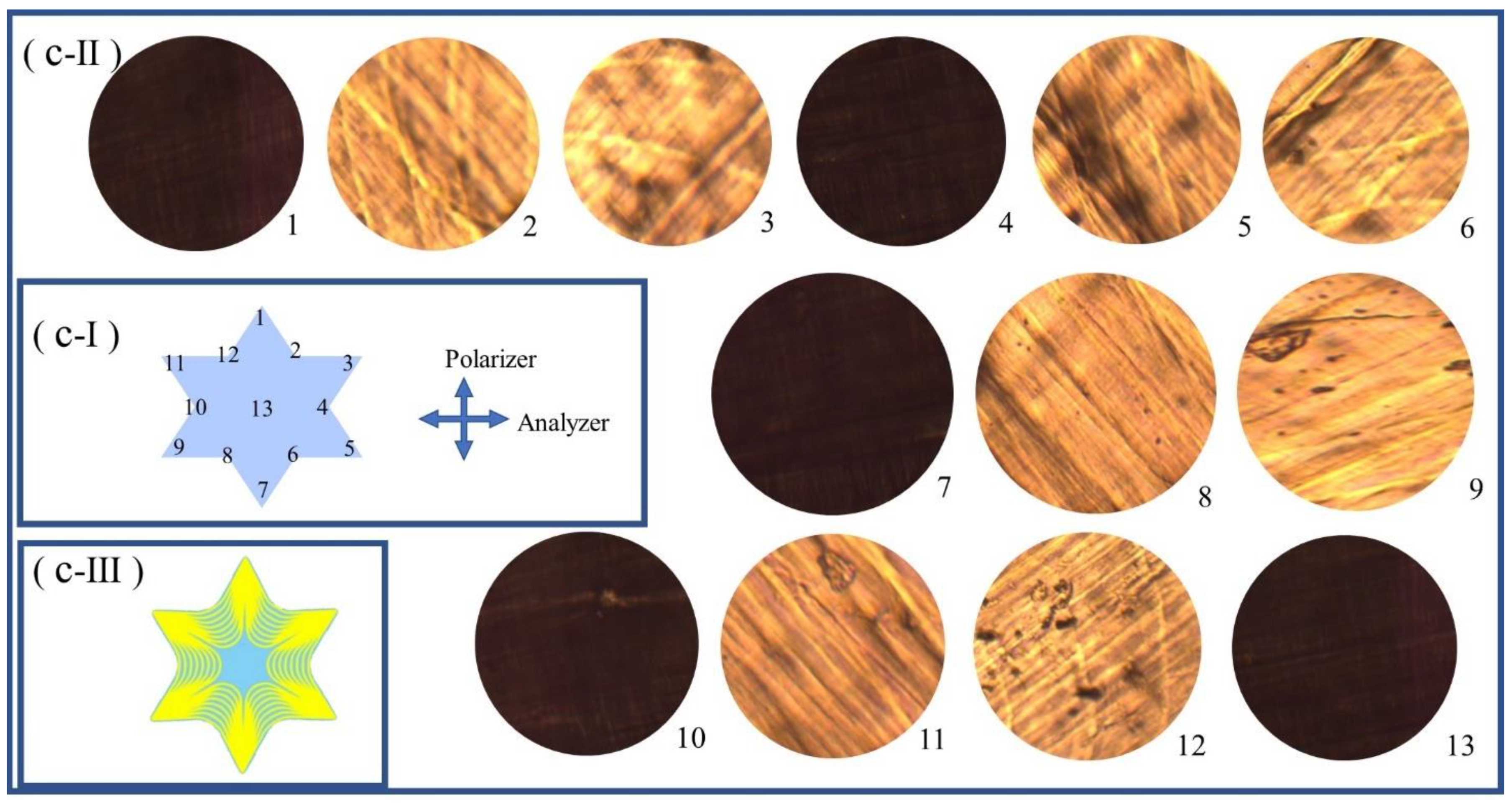


| Programmed shape | Reactant amounts | |||||
|---|---|---|---|---|---|---|
| LC44 | LC66 | TMDSO | PMPOPS | Toluene solvent (µL) | Catalyst solution (µL) | |
| 1D shape: Strip shape | 0.1692g (0.5mmol) | 0.1973g (0.5mmol) |
0.1072g (0.8mmol) |
0.0268g (0.08mmol) |
1300 | 25 |
| 1D shape: Rod shape | 0.0423g (0.125mmol) | 0.04933g (0.125mmol) |
0.0268g (0.2mmol) |
0.0067g (0.02mmol) |
330 | 8 |
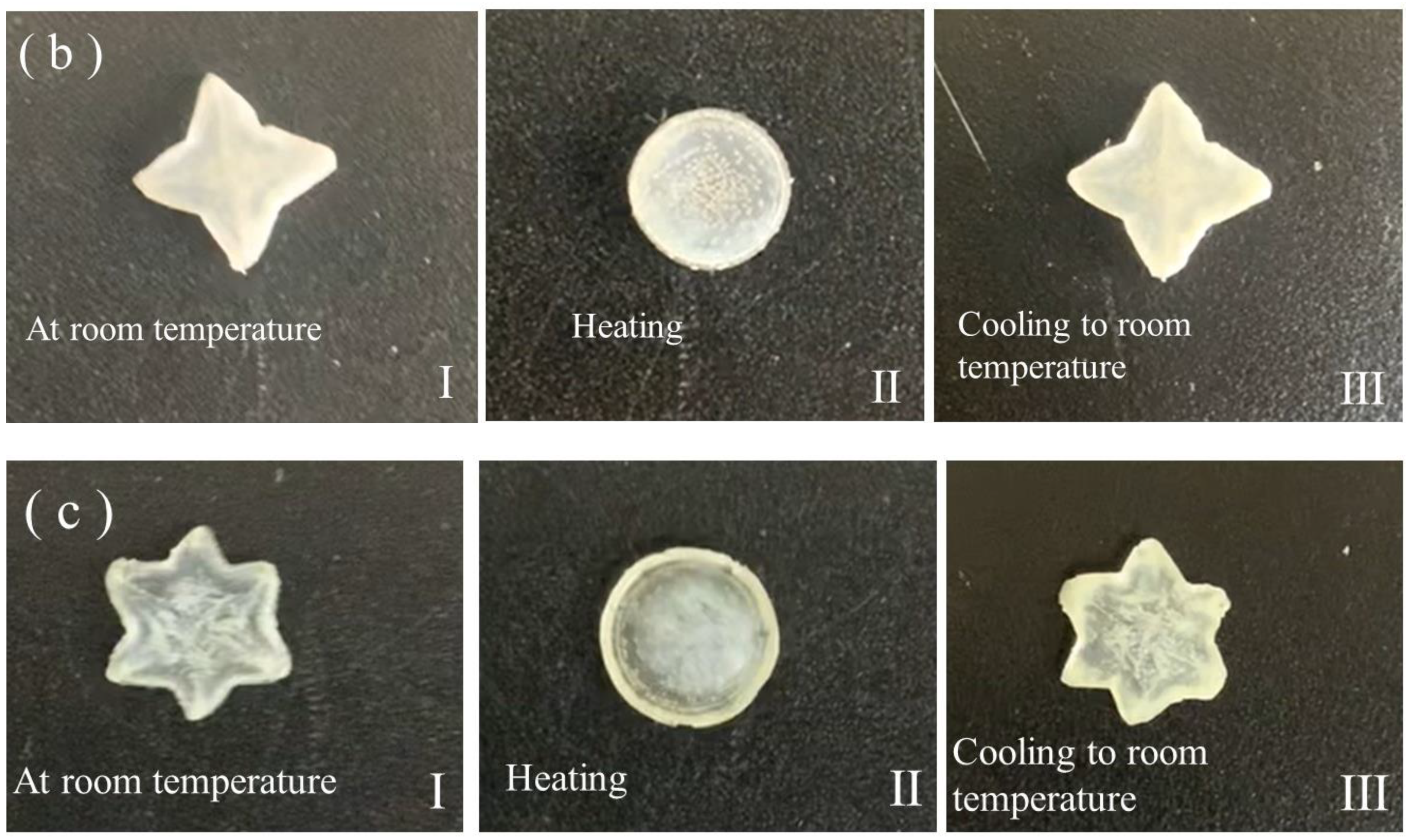
| 2D shape: Six-pointed star, four-pointed star or regular triangle | 0.0846g (0.25mmol) | 0.09865g (0.25mmol) |
0.0536g (0.4mmol) |
0.0134g (0.04mmol) |
650 | 12 |
| 3D shape: “3D-S-LCE”, “3D-E-LCE” or “3D-SE-LCE” | 0.0846g (0.25mmol) | 0.09865g (0.25mmol) |
0.0536g (0.4mmol) |
0.0134g (0.04mmol) |
650 | 12 |
| Programmed shape | fcure | fheat | fcool |
|---|---|---|---|
| Rectangular strip | 98.1 % | 98.8 % | ≈100 % |
| Round rod | 97.9 % | 98.3 % | ≈100 % |
Disclaimer/Publisher’s Note: The statements, opinions and data contained in all publications are solely those of the individual author(s) and contributor(s) and not of MDPI and/or the editor(s). MDPI and/or the editor(s) disclaim responsibility for any injury to people or property resulting from any ideas, methods, instructions or products referred to in the content. |
© 2023 by the authors. Licensee MDPI, Basel, Switzerland. This article is an open access article distributed under the terms and conditions of the Creative Commons Attribution (CC BY) license (https://creativecommons.org/licenses/by/4.0/).


