1. Introduction
Nowadays, woven roving composites are very significant class of high performance composites materials due to various aspects dealing with the improved damage tolerance in the comparison of unidirectional composites (UD). The simplicity of their use in the closed mold process and of the possible applications in various, complicated engineering structures (e.g., aerospace, building, mechanical problems) prefer their use in different industrial problems. However, the stiffness and the strength of the yarn woven fabric composites are lower than those for UD composites. Therefore it is necessary to evaluate static and fatigue mechanical properties of woven roving composites to define and describe the sense of their possible applications – e.g., wind turbine blades, aerospace, automative. Referring to the variety of manufacturing processes it is necessary to distinguish the various mechanical behaviour of 2-D, 2.5-D, and 3D woven roving composites.
One of the possible classifications of composite materials refers to the form of the reinforcement – particulate reinforcements, whisker reinforcements, nanostructural reinforcements (nanoplatelets, nanoribbons, various forms of graphens – hexagonal nanostructures), continuous fiber laminated composites, and 2-D, 2.5-D or 3-D woven composites (braided or knitted fiber architecture).
To obtain more comprehensive information on woven roving composites the reader should study the following classical works dealing with Textile Structural Components : Bogdanovich, Pastore [
6], Naik [
7], Tong et al. [
8]; books/monographs : Design and Manufacture [
9], Composite Forming Technologies [
10], Composite Reinforcement for Optimum Design – Boisse (edt) [
11], Non-crimp Fabric Composites – Lomov (edt) [
12], Fiber Architectures for Composite Applications – [
13], online encyclopedias (Blokley, Shyy (Edts) [
14]), (H. Altenbach, A. Ochsner (Edts) [
15]), Handbook of Epoxy/FiberComposites [
16], and proceedings of Textile Composites conferences.
1.1. A brief description of 2-D woven roving composites
The category of fiber architecture is that formed by 2-D,2.5-D or 3-D weaving, braiding, or knitting the fiber bundles or “tows” to create interlocking fibers that often have orientations slightly or fully in an orientation orthogonal to the primary structural plane. This approach is taken for a variety of reasons, including the ability to have structural, thermal, or electrical properties in the third or “out-of-plane” dimension. Another often- cited reason for using these architectures is that the “unwetted” or dry fiber preforms (fibers before any matrix is added) are easier to handle, lower in cost, and conform to highly curved shapes more readily than the highly aligned, continuous fiber form.
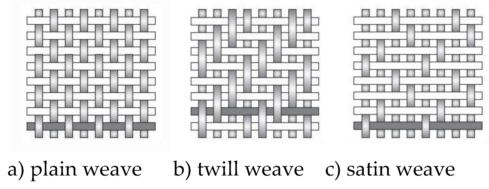
Three different types of 2-D woven roving composites are distinguished –
Figure 1.
Woven fiber-reinforce plastics are becoming increasingly important because they have the following advantages over laminates made from individual layers of unidirectional material:
Their cost efficiency
High processability, particularly, in lay-up manufacturing of large scale structures due to Improved formability and drape
Bidirectional reinforcement in a single layer
Improved impact resistance
Balanced properties in the fabric plane
The woven composite is formed by interlacing two sets of threads, the warp and the weft, in a wide variety of weaves and balances.
The lay-up attributes of woven prepregs are:
Thicker (therefore fewer) layers and faster lay-up rate
Much higher curvature conformability and hence lower susceptibility to wrinkling
Greater material width of 1.25 or 1.7 m (4.1 or 5.6 ft) compared to 0.3 or 0.6 m (1 or 2 ft) for tape prepreg. (Tape prepreg is narrow since it has low conformability, and materials waste is high for wide tape.)
Lay-up rates are therefore approximately 3 to 5 times higher than for unidirectional tape.
No requirement to butt strip edges since fabrics are wider than the parts
Less-precise ply orientation is required since the lay-up is less optimized; lay-up can therefore be faster.
Manufacturing disadvantages of woven prepregs are:
Higher proportion of waste from the wider material
Higher cost of low-thickness fabric prepreg since the weaving process preceding prepregging is an added cost. Thicker woven prepreg with a fiber areal weight (FAW) of 370 g/m2 has become standard since the weaving cost is around half that of the conventional 285 g/ m2 fabric. These thick prepregs reduced stiffness to the resultant components.
1.2. Design, Tooling, and Manufacturing Interaction
A draping simulation is used to generate fiber paths, identify areas of wrinkling and bridging, develop flat patterns, and allow the calculation of local ply orientations and the resulting laminate mechanical properties, such as stiffness, permeability, volume fraction, and thickness. The existing models for draping simulation fall into one of the following two categories: mapping models and mechanical models. Mapping models assume a geometric mechanism to transform an initial unit square of fabric into the corresponding draped shape. Mechanical models use the equilibrium equations that balance the internal forces in the fabric with external applied loads.
The above problems are very significant in manufacturing curved structures made of 2-D woven roving fabrics. For instance considering hemispherical shells the length of the meridian is equal to πR, and the maximal length of the circumference to 2πR, where R denotes the shell radius. The excess of the material along the circumference leads to the wrinkling of the produced curved structures. Those problems are discussed for shallow ellipsoidal domes by Gohari et al. [
17], curved structures by Wang et al. [
18], Potluri et al. [
19], Sharma, Sutcliffe [
20], torispherical shells by Galletly, Muc [
21] or hemispherical domes by Muc [
22]. For all cases discussed above the rectangular form of 2-D woven roving composites (e.g.,
Figure 1a) changes to rhombs. It leads to the unsymmetric mechanical description of the axisymmetric shell constructions. It should be included in the numerical analysis.
The use of filament winding method can eliminate the appearance of wrinkles along shells circumference both for opened or closed shells but it does not eliminate the unsymmetric deformations of axisymmetric domes.
1.3. Notches/holes in structures made of woven roving composites.
In general for composites, the notch sensitivity and stress concentration around the holes problems can be divided into four categories:
Strength performance of laminated unidirectional constructions [
23,
24,
25,
26,
27,
28]
2-D braided composite structures [
29,
30,
31,
32]
2.5-D woven roving composites Guo et al. [
33], Song et al. [
34]
The investigations in each of the above mentioned areas tend to introduce the more accurate description of numerical modeling to experimental results. The investigation on 2-D, 2.5-D, and 3-D textile composite structures with various shapes of notches is very rare. Pandita et al. [
4] demonstrate experimental and theoretical static strain concentrations results for circular, and vertical, and horizontal ellipsoidal centrally located holes. Guo et al. [
33] describe the results for centrally located waist, slit, octagon, square, hexagon and rhombus holes.
As it is pointed by Guo et al. [
33] the present studies are mainly directed in the analysis of structures made of 3-D woven roving materials. The identical conclusions can be drawn in the literature concerning with the fatigue reliability.
1.4. The goals of the present investigations
The aim of the present work is to present the comparison of experimental and theoretical (numerical) studies for plates (specimens) made of 2-D woven roving composites. The analysis deals with constructions of centrally located holes and subjected to tensile loading. Since the static experimental studies demonstrate an evident material nonlinear (σ-ε) characteristics the fatigue numerical (finite element) description is carried out with the use of the low fatigue cycle (LFC) method. The experimental (static and fatigue) results illustrate essentially the occurrence of the random (probabilistic) nature of both static and fatigue cracks. The classical approach to such problems is based on the statistical (Weibull) distributions. However, in such a description, a lot of experimental data is required. Therefore, we propose to use herein the limit data (lower and higher bounds) to characterize the LFC behaviour of structures.
In the present paper we intend to discuss similarities and differences for static and fatigue behaviour of plates made of 2D woven roving composites having central holes and subjected to uniaxial tension. The analysis is conducted with the application of experimental results with the finite element computations.
2. Static and Fatigue Analysis of 2D Woven Roving Specimens
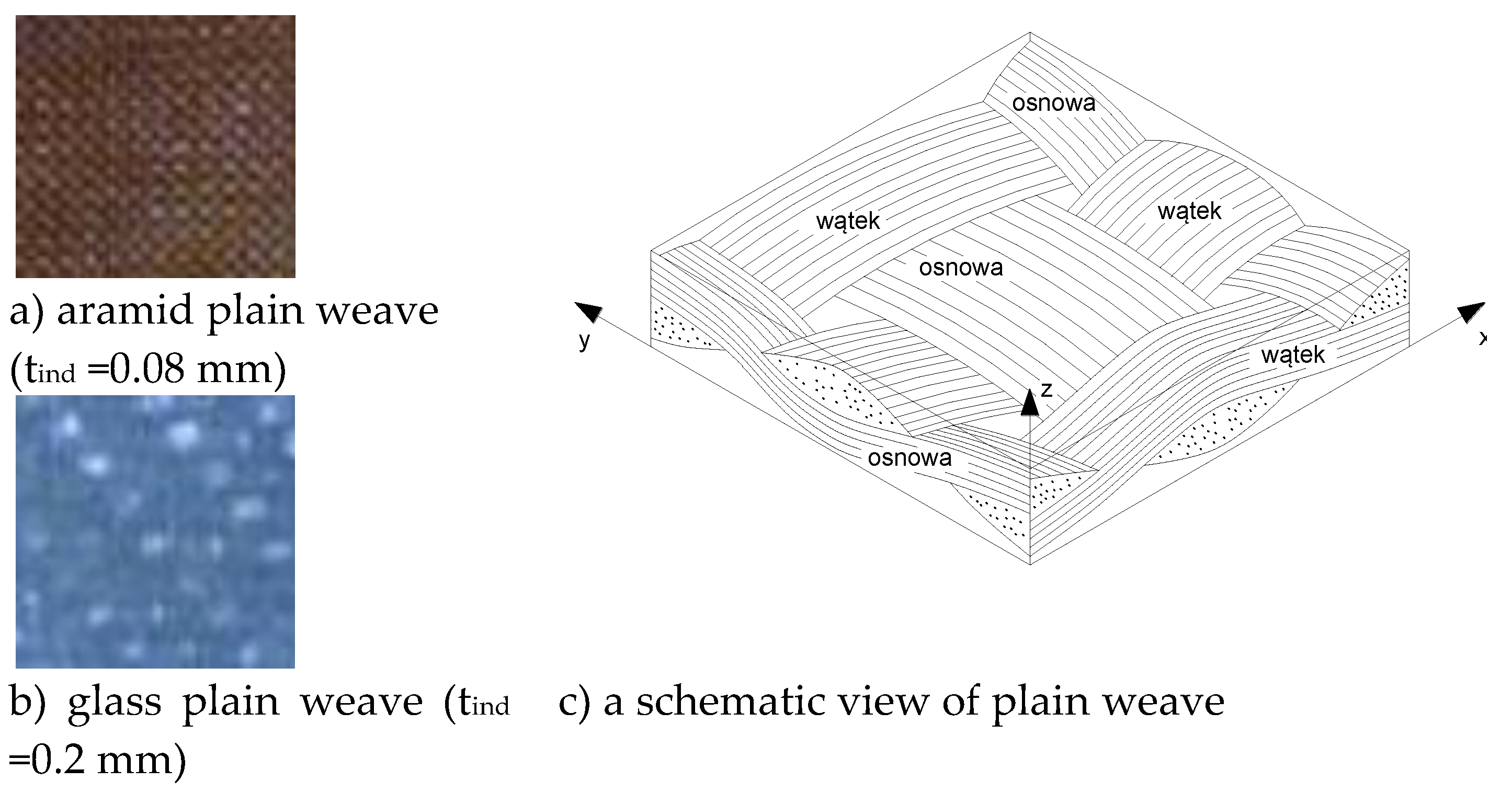
Due to manufacturing process textile composites have specific geometrical forms and possess specific periodic geometrical patterns – see
Figure 2. The analysis deals with the plain 2D woven fabric. The geometry of the cross-sections of 2D woven fabric have a crucial influence of the derivation of mechanical properties. The homogenized mechanical properties can be determined with the use of experimental tension tests or by the numerical finite element analysis.
Figures 2a and
2b depict the photographs of 2D woven composites having different thicknesses of bundles corresponding to packing density of fibres.
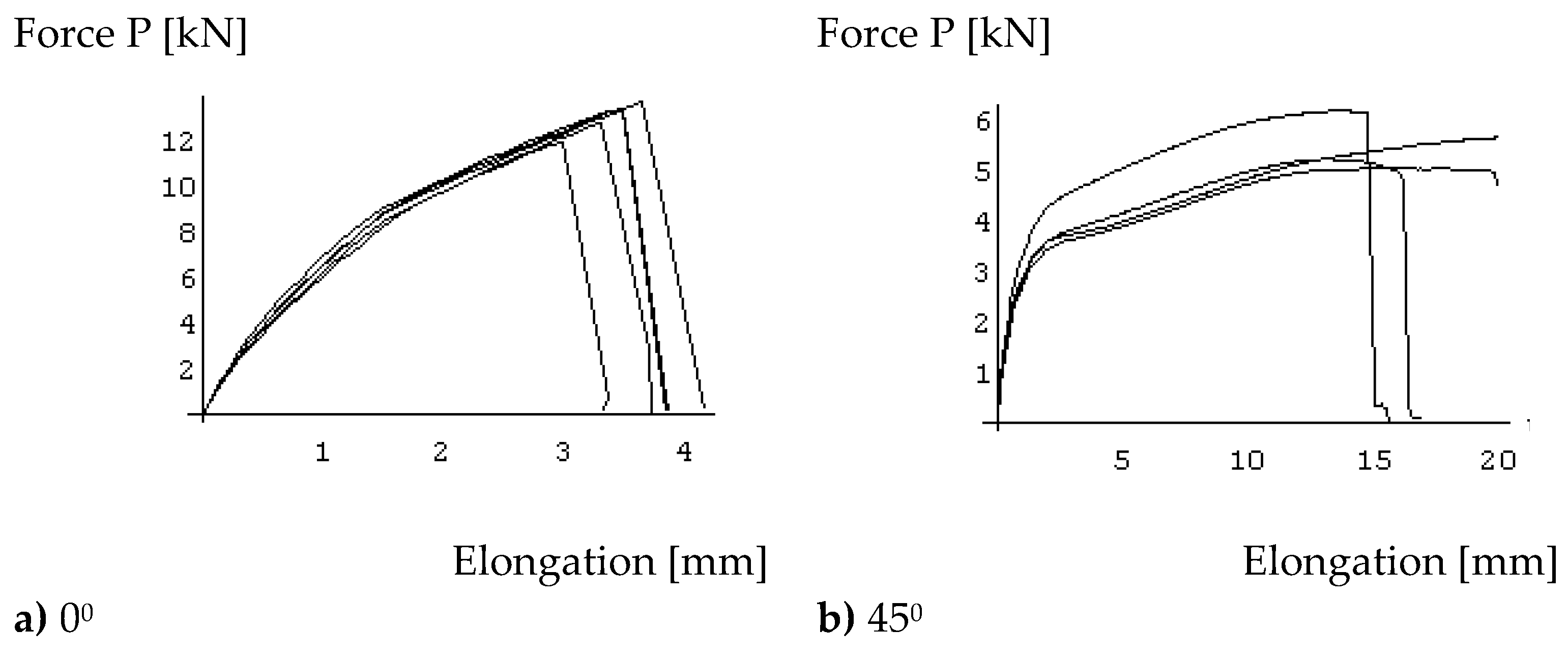
Using the experimental results plotted in
Figure 3 the average Young’s and Kirchhoff’ moduli are written in Table 1- see Ref [
40.
To model mechanical properties of 2-D woven roving composites two possible approaches can be used – see e.g., L. Wang et al. [
41]:
Two level modeling where at the first level the fiber bundle (tow) is represented in the microscale and at the second level the representative volume element (RVE) is illustrated and modeled in the mesoscale
One level modeling (mesoscale) where the mesh of composites (RVE) contains three parts: resin pocket, warp tows and fill tows – each of the part is represented by 3-D (hexahedron) finite elements
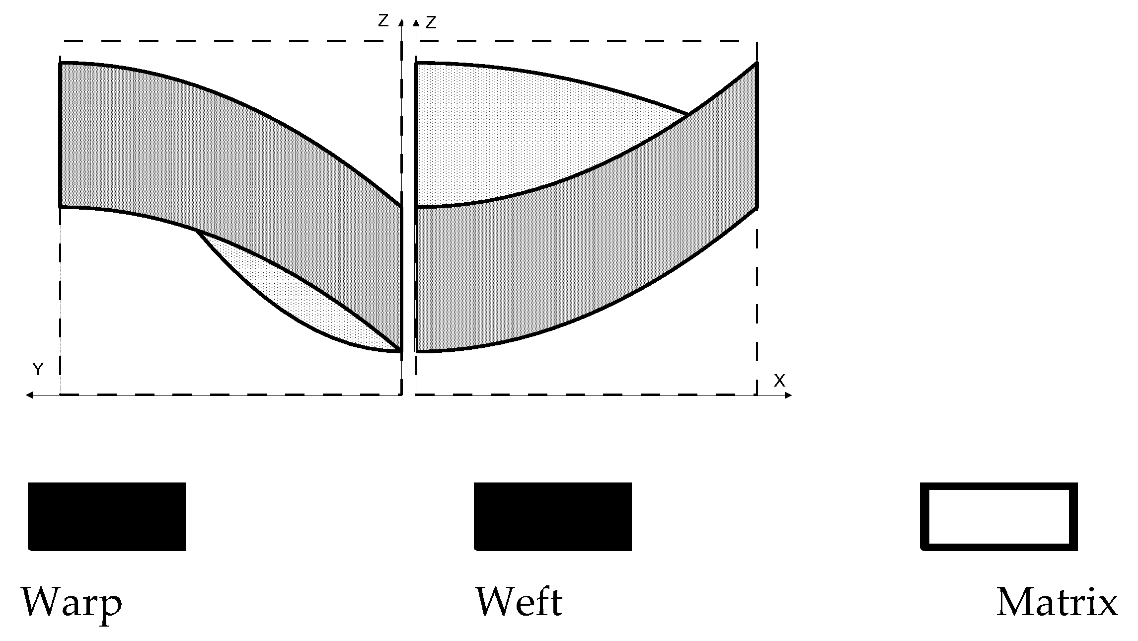
The homogenization can be also carried out for the unit cell presented in
Figure 4 – see Refs [
42,
43]. They are dependent on the form of the cross-sections that are demonstrated in
Figure 4. The agreement between experimental and numerical results is very good. In addition, let us note that the values of the Young’s moduli for warp and weft directions are almost the same.
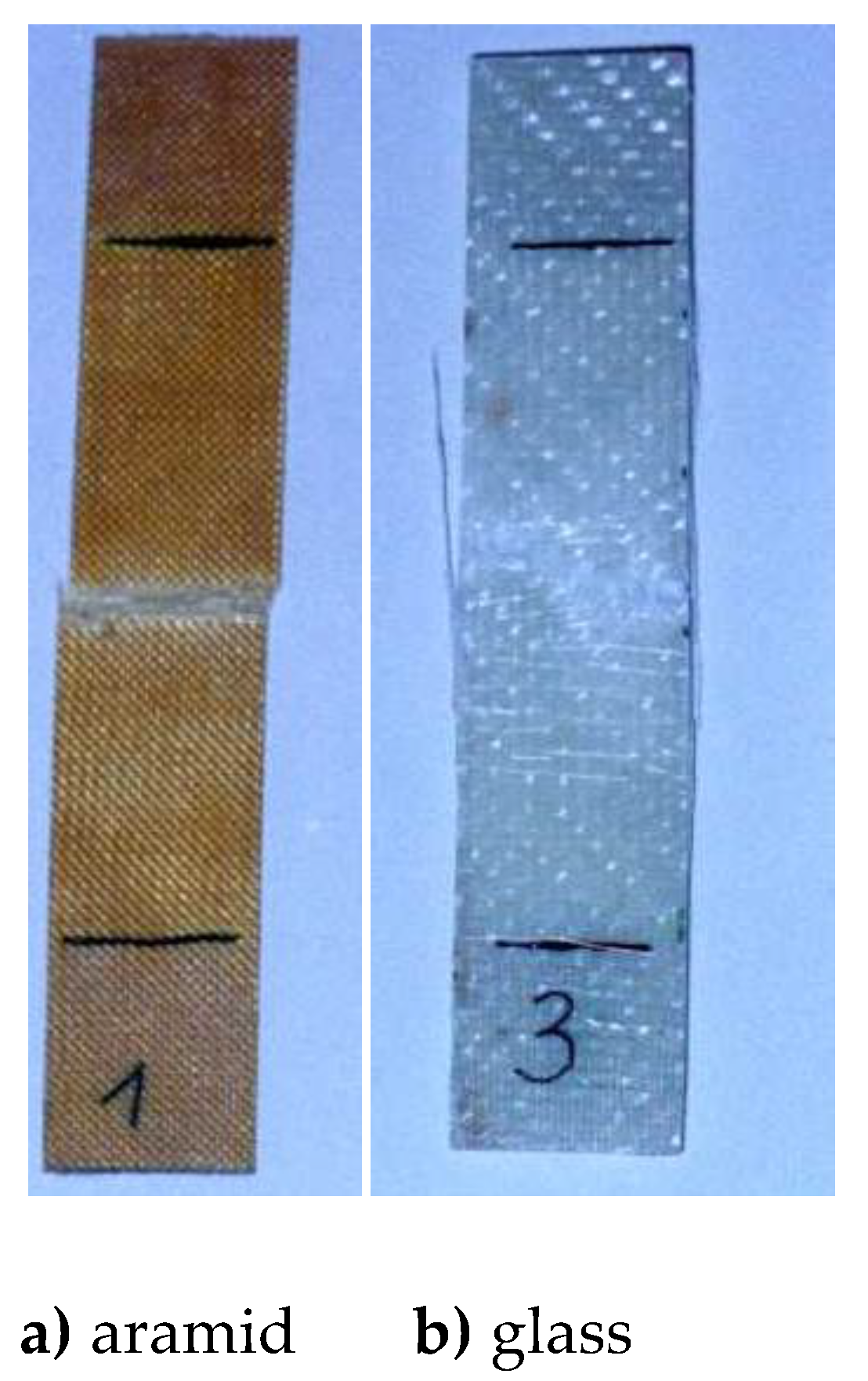
The failure modes of rectangular specimens are presented in
Figure 5. The damage occurs in the perpendicular direction to the tension load. Since the thickness of the aramid specimen is very low (
Figure 2) its mechanical behaviour (σ-ε curve) is almost linear and the failure is characterized by a brittle fracture. For glass woven roving the deformation (
Figure 3) is nonlinear and can be described by elastic-plastic bahaviour. The failure is not localized along one line (compare
Figure 5a and
Figure 5b). It is observed that failure forms is associated with delaminations illustrated by white zones.
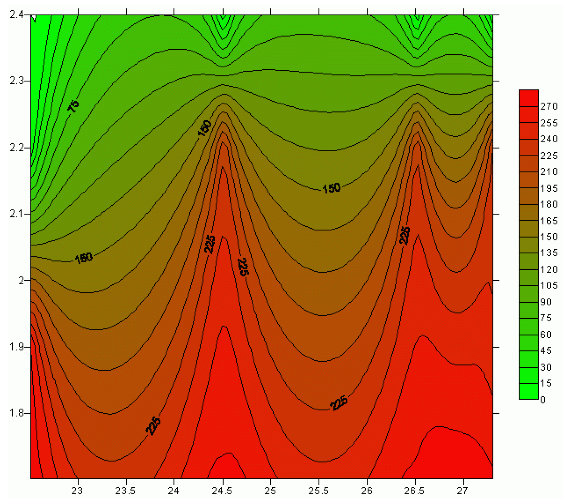
It is mainly caused by the non-uniform thickness distributions of glass specimens. It has a significant influence on the load distributions along specimens at the particular points as it is plotted in
Figure 6. The broader discussion of those problems is presented by Muc [
44]. For woven roving composites the scatter of results is usually observed.
Usuallly, as it discussed in Ref [
45] for 2D woven composites (fabric formed by interlacing the longitudinal yarns (warp) and the transverse yarns (weft)), such as plain, twill or satin), four types of damage mechanisms occur under static and fatigue loadings: intra-yarn cracks in yarns oriented transversely to the loading direction, inter-yarn decohesion between longitudinal and transverse yarns, fiber failure in longitudinal yarns and yarn failures. The failure forms plotted in photographs in
Figure 5 are identical for fatigue problems.
3. Stress Concentration around Convex Holes – Static Behaviour.
The existence of holes in woven roving composite constructions leads to the significant stress concentrations around notches. The continuum damage mechanics of unidirectional laminates is illustrated by Muc, Ulatowska in Ref [
2]. The static and fatigue description of constructions with holes made of woven roving composites is discussed in Refs [
45,
46,
47,
48,
49,
50,
51]. The authors compared the static and fatigue behaviour of unnotched and notched composites
3.1. Definition of Convex Holes
A lot of planar convex curves can be expressed in the form of the super-ellipse defined in the following way – see Muc [
1]:
where
a, b and
n are positive rational numbers. A supercircle will obviously correspond to setting
a =
b. For each value of
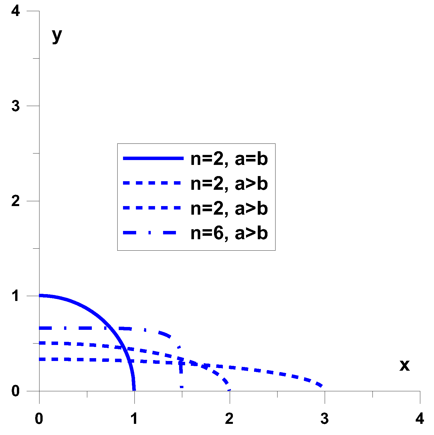
n – the supercircular exponent – we obtain a different convex curve. The shapes of the supercircles for different values of
n are shown in
Figure 7. Evidently,
n = 2 corresponds to a circle whereas
n= 1 corresponds to a triangle with its sides rotated by an angle of
π/4 . The case
also corresponds to a square with its sides parallel to the axes. Finally, the curve characterizing the convex hole (the supercircle) can be represented in the form of the Fourier series:
The above relation exploits the symmetry with respect to the OX and OY axes.
Applying the form of the curve (1) one quarter of the surface closed by the superelipse can be written in the following form:
where Γ(…) denotes the Euler gamma function.
3.2. Static failure investigations of specimens with holes
A series of experiments were carried out to study damage of specimens with circular holes. The plates made of 2D woven roving glass (see
Table 1 and
Figure 2 and
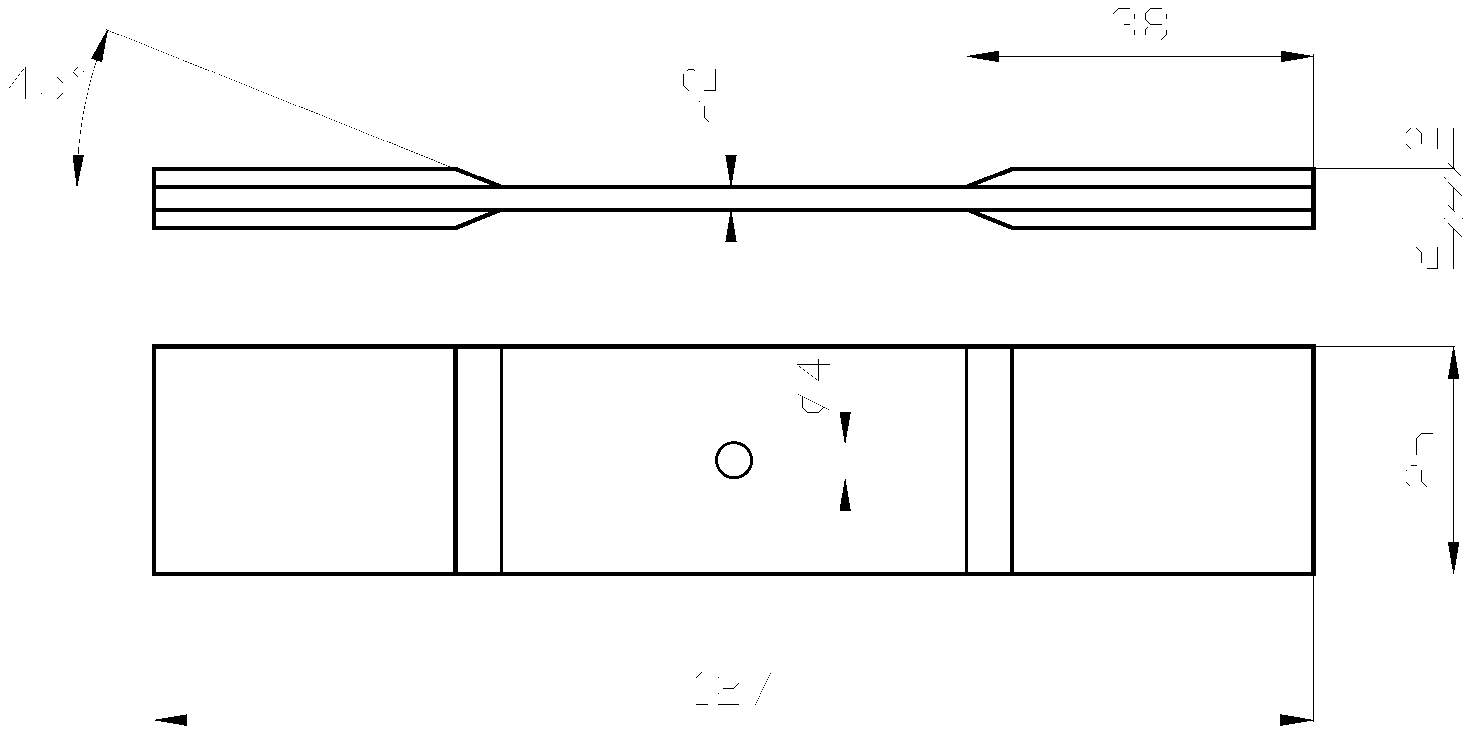
Figure 3) were subjected to the uniaxial tension. The geometry of the specimens is presented in
Figure 8.
Let us note that the ratio: the width to the hole diameter is equal to 25/4 = 6.25. For such values of the ratio the influence of the hole can be neglected at the end of the width as it demonstrated for unidirectional laminates [
3]. For 2D woven roving composites the analogous effects are also observed and are computed below with the aid of the finite element method.
Figure 9 demonstrates the forms of the final damage of the specimens. As it may be seen the failures occur always in the perpendicular direction to the tensile loads similarly as for isotropic materials. However, the failure mode is associated with the inelastic deformations of the matrix – white zones in
Figure 9.
The 2-D solid elements (plane stress elements NKTP = l) in the NISA finite element package are included in the present analysis. The element may be shaped as a 4 to 12 node quadrilateral, or as a 3 or 6 node triangle depending on the selected approach. Each node has two degrees of freedom (two displacements ux, uy) and the state of stress is characterized by three components: σx , σy and σxy. In addition, the nonuniform thickness distributions at each of the nodes can be introduced. The influence of the meshing on the accuracy of computations will be discussed and illustrated later.
Using the planar finite elements it is possible to evaluate numerically the stress distributions around the holes.
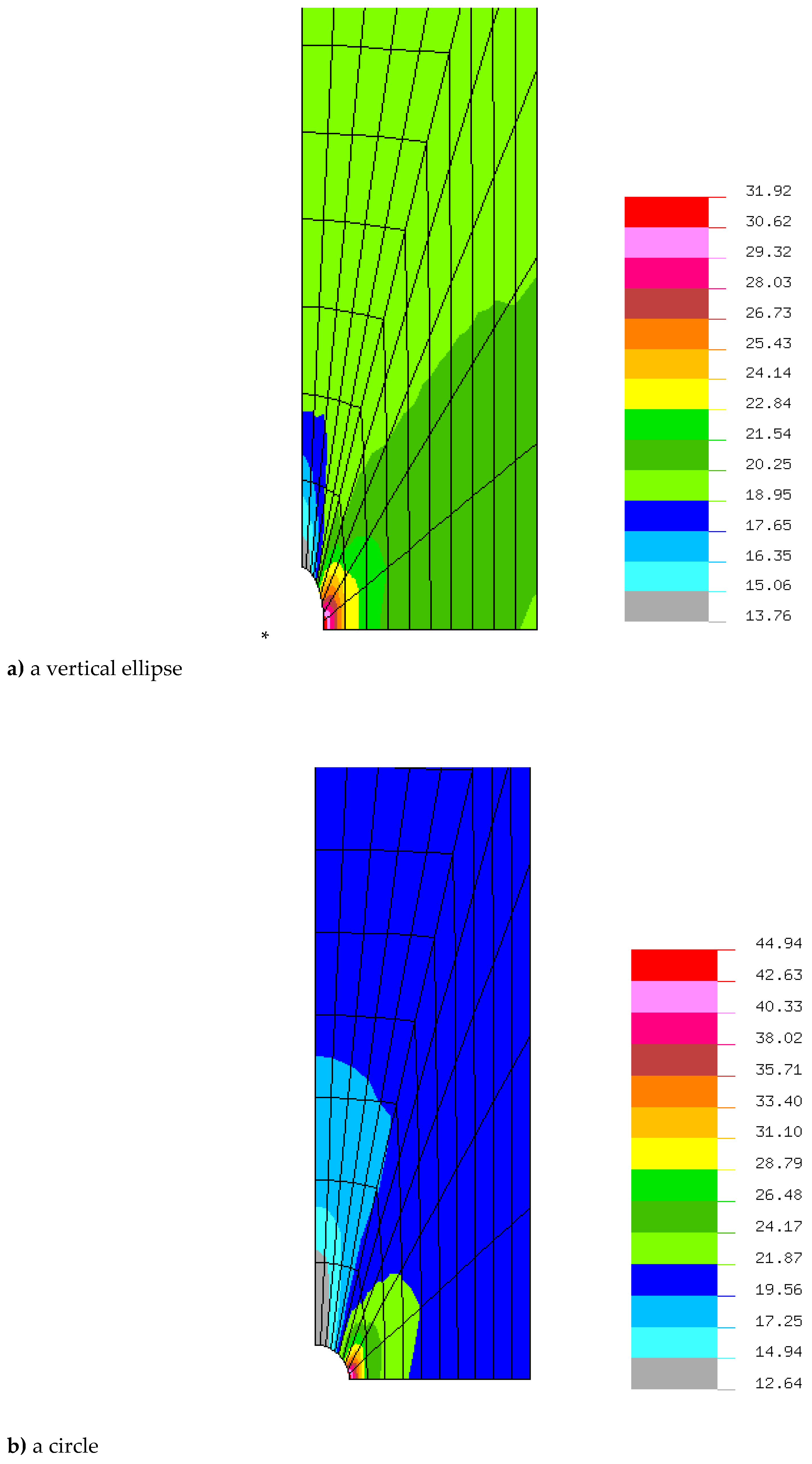
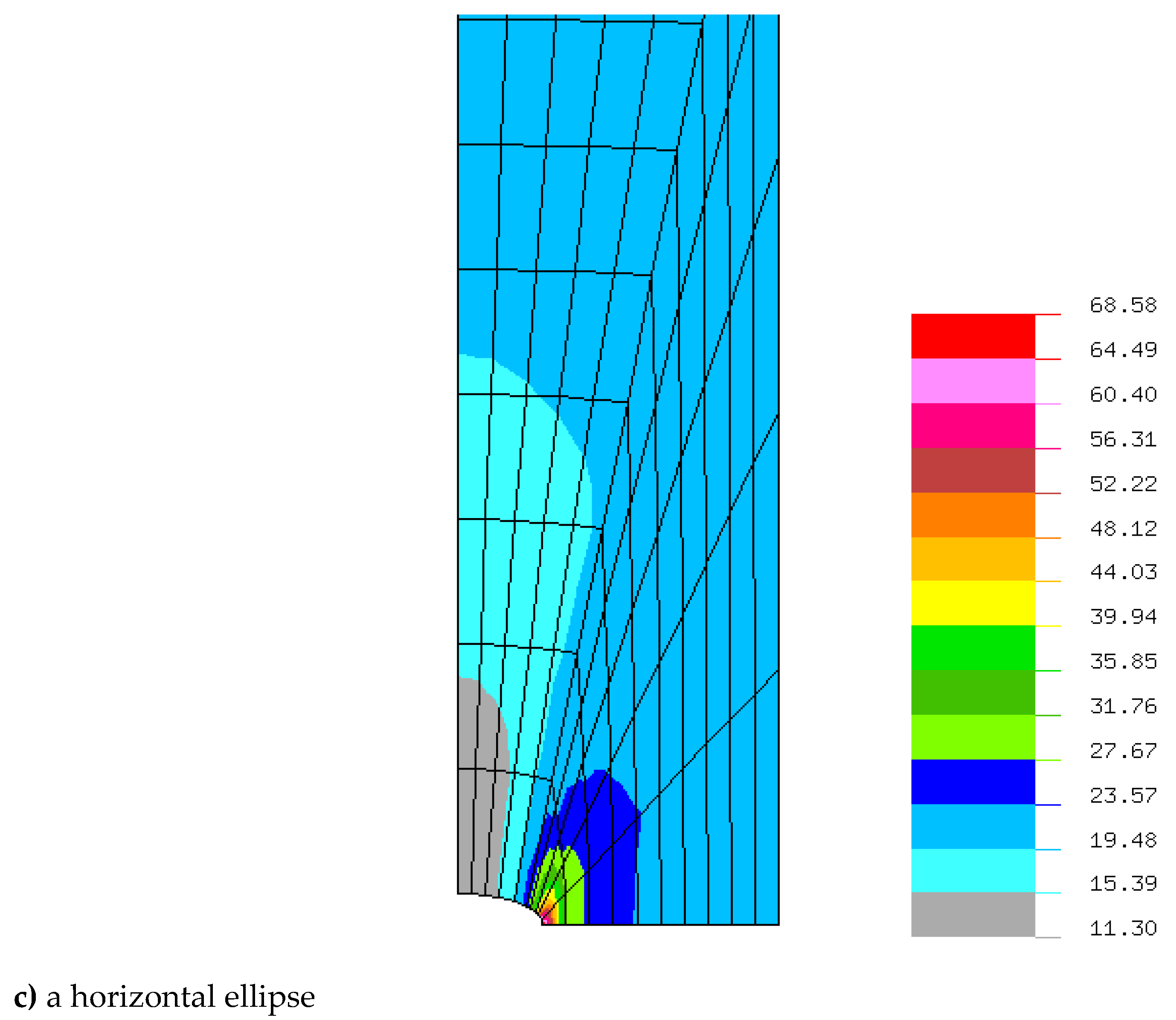
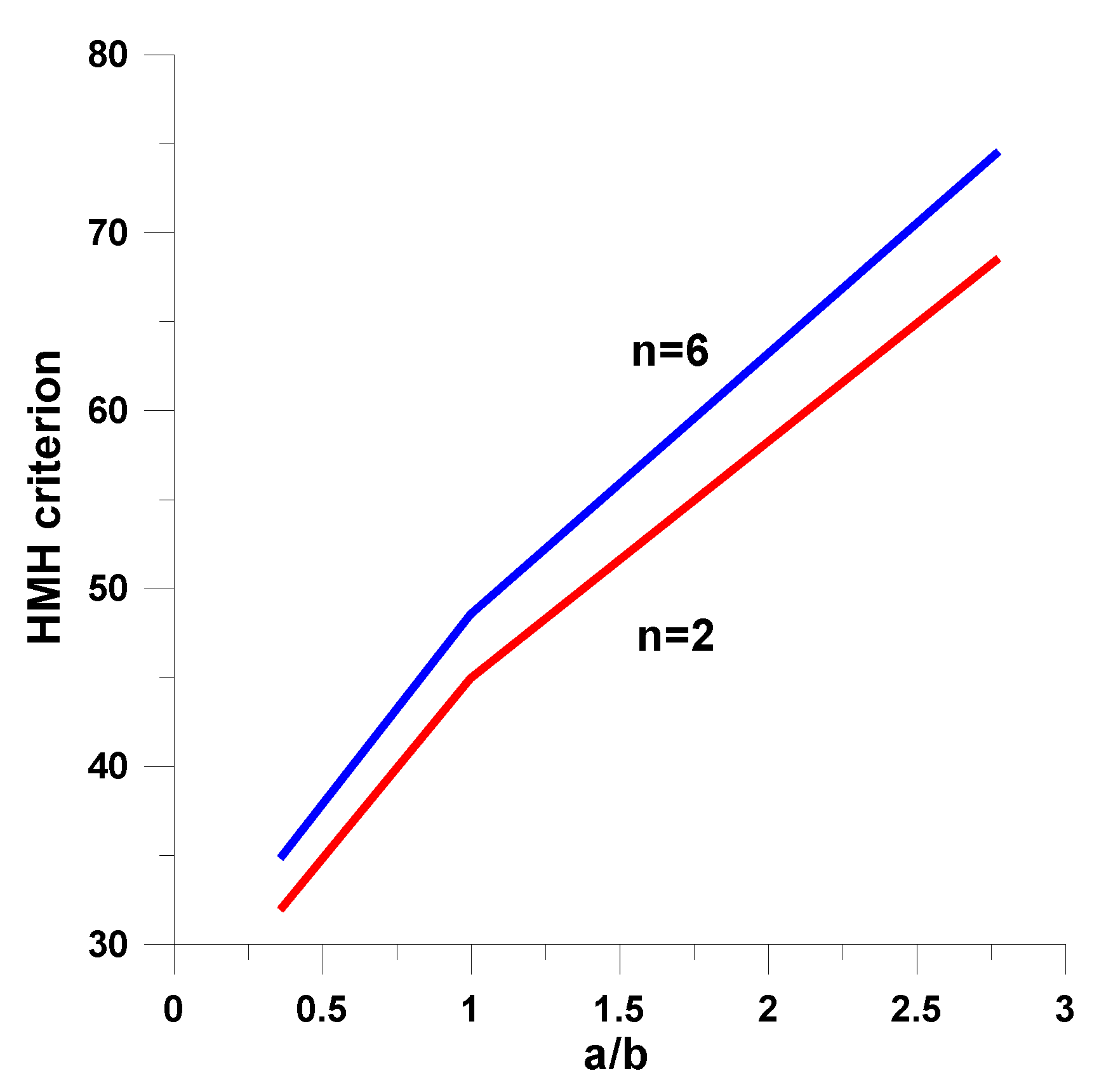
Figure 10 illustrates the plots of the static stress concentrations around the convex holes (1). The maximal stress concentrations occurs at the tip of the notch. The stresses are related to the value: P/(Wt).
As it may be noticed in
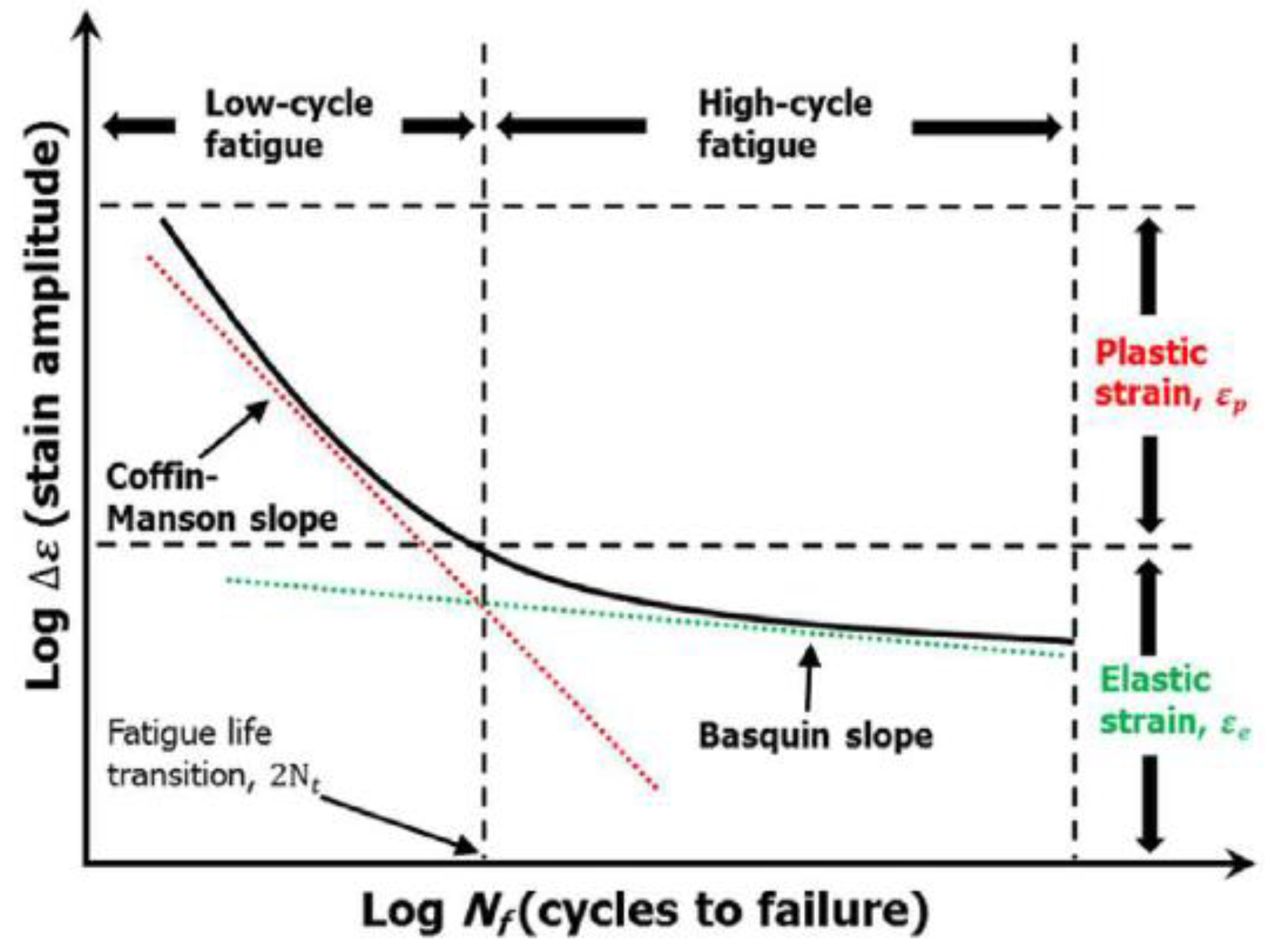
Figure 11 the stress concentrations increase with the growth of the ratio a/b (see Eq (1)). The identical behavior occurs for the higher values of the n parameter (i.e., n=6), keeping the same values of the area A
c. The similar effects are obtained for plates with holes made of woven roving composites, isotropic materials or laminated composites as it is discussed by Pandita ,Nishiyabu, Verpoest [
4] and Muc, Romanowicz [
3]. In general, various stress criteria can be employed in the analysis. We are searching for the maximal values of:
The circumferential stresses
The Hill criterion
*The Huber-Mises-Hencky citerion
The Tsai-Wu criterion
The Hashin 3-D or 2-D criterion
The detailed description of the above criteria is presented e. g. in Ref. [
52].
Since in the present analysis and modeling 2-D bidirectional woven roving plain composite materials can be treated as isotropic materials (see
Table 1 – the mesoscale analysis) the strain concentration factors can be approximated by the results valid for isotropy. The ratio between the local stresses around the hole and the nominal stresses is characterized by the stress concentration factor k
t1, i.e.,:
where the nominal stress
, and the local stress
corresponds to the value of the σ
y stress component at x = a and y = 0 (the edge of the hole). The theoretical stress concentration factor is a function only of geometry and the type of loading, and can be determined either analytically (using the theory of elasticity), through finite element analysis, or through experiments.
For isotropic materials the stress concentration factor of an elliptical notch can be described in the following way:
Considering the values of the coefficients 1+2b/a one can notice that the horizontal ellipses correspond to the high concentration effects, whereas the vertical position of ellipses corresponds to the low concentration effects. The comparisons of the stress concentration factors (4) are demonstrated in
Table 2.
The accuracy of the FE approximations is a function of the accuracy of meshing, however, in the present case is quite good. Pandita et al. [
4] obtained the unsymmetric behaviour of failure modes. It is difficult to verify such results since it depends on too many factors.
Let us note that for the parameter n greater than 6 the area A
C Eq. (2) can be approximated by the value ab(1-0.5/n). Therefore, the growth of the ratio a/b and the parameter n corresponds to the increase of the stress concentration factors and/or the HMH factor (
Table 2 and
Figure 11).
4. Fatigue behaviour of notched woven roving 2D composites
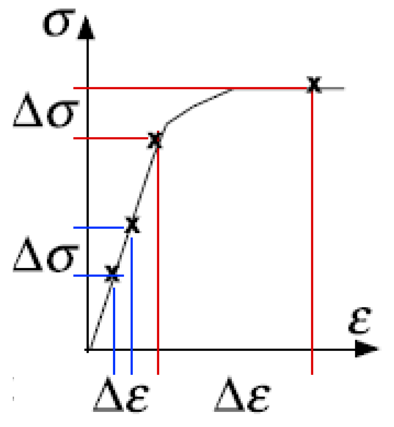
Nowadays,the fatigue of structures can be approached using the following concepts –
Figure 12:
4.1. Low cycle fatigue (LCF)
In the further part of the paper the LCF problems are investigated.
Low cycle fatigue (LCF) from Coffin [
53] and Manson [
54] – only finite fatigue life is possible and can be considered using the LCF criteria in such a case a small strain increment corresponds to a large stress increment –
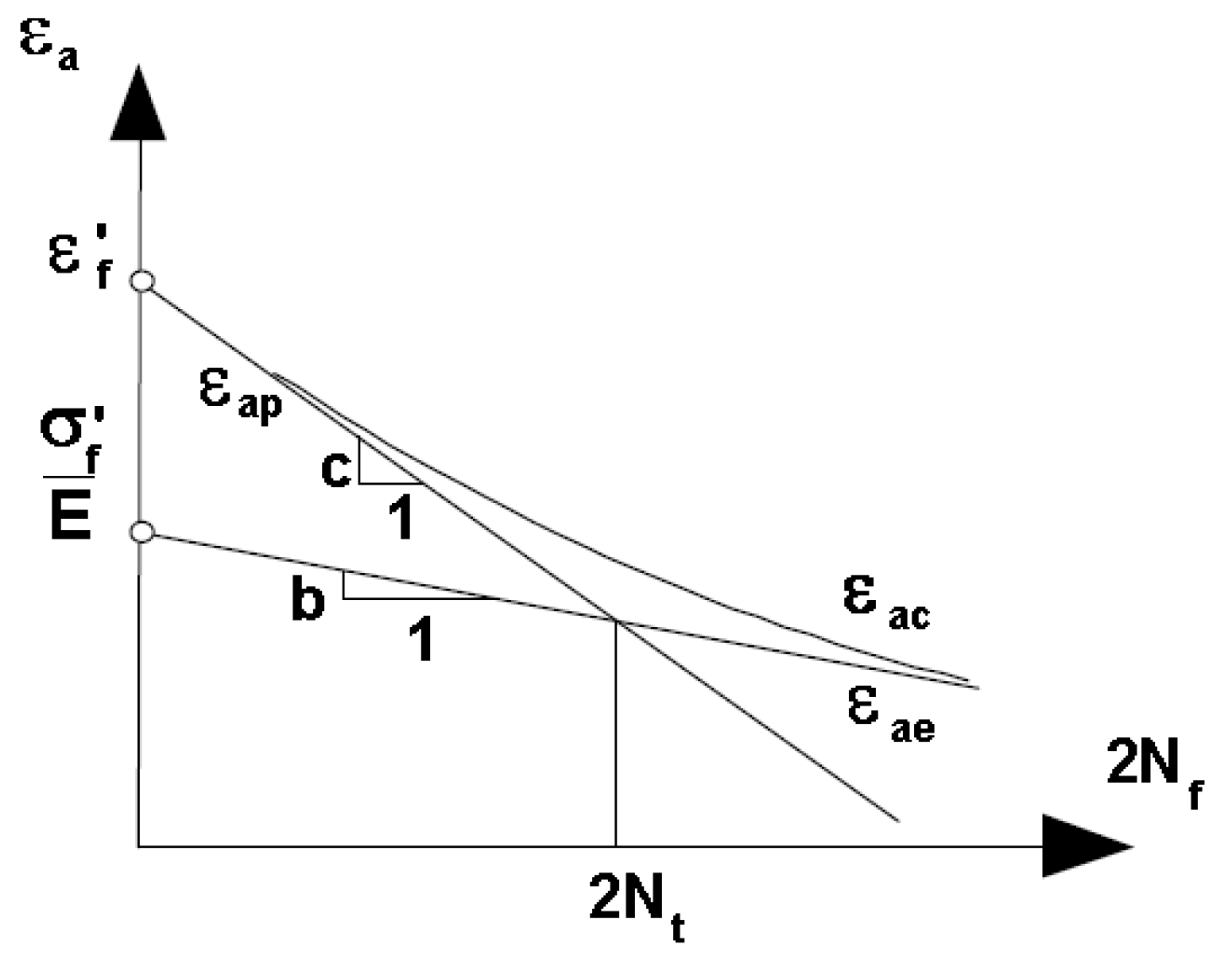
Figure 13; according to this approach, the fatigue life of a member subjected to fully reversed constant amplitude strain-controlled loading is given by an equation of the form:
where: ε - total strain amplitude,
- fatigue strength coefficient,
b - fatigue strength exponent,
- fatigue ductility coefficient,
c - fatigue ductility exponent, E - modulus of elasticity, N
f - reversals to failure; the determination of coefficients is presented schematically in
Figure 14;
The LCF curve is defined by five coefficients. Manson proposed the method of universal slope where the equation for the method can be given as follows:
where UTS denotes the ultimate tensile strength, D is the ductility , i.e., the percentage reduce of the area.
4.2. Experimental Analysis
Since the static stress-strain curves demonstrate the evident nonlinear behaviou (
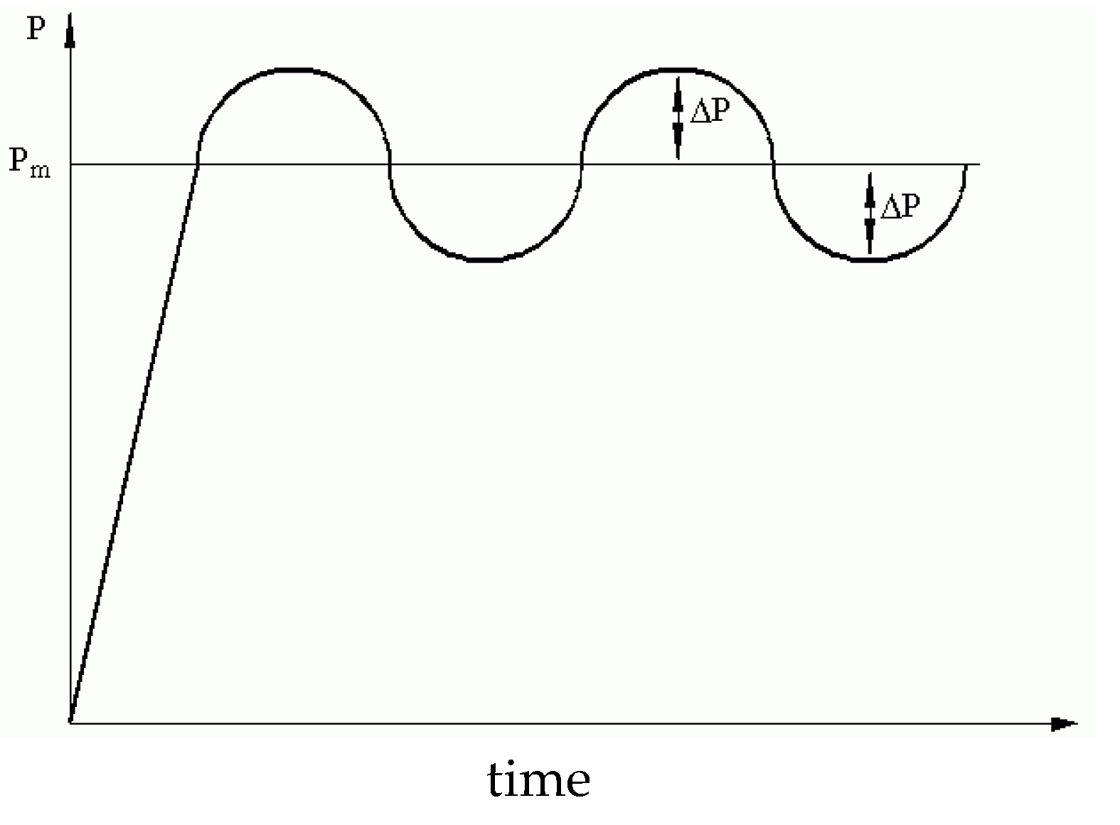
Figure 3a) the fatigue analysis is carried out with the use of the LCF method where the static load carrying capacity is not exceeded. The form of the tensile load is illustrated in
Figure 15 where P
m = 0.8 P
static and ΔP = 0.1 P
m.
time
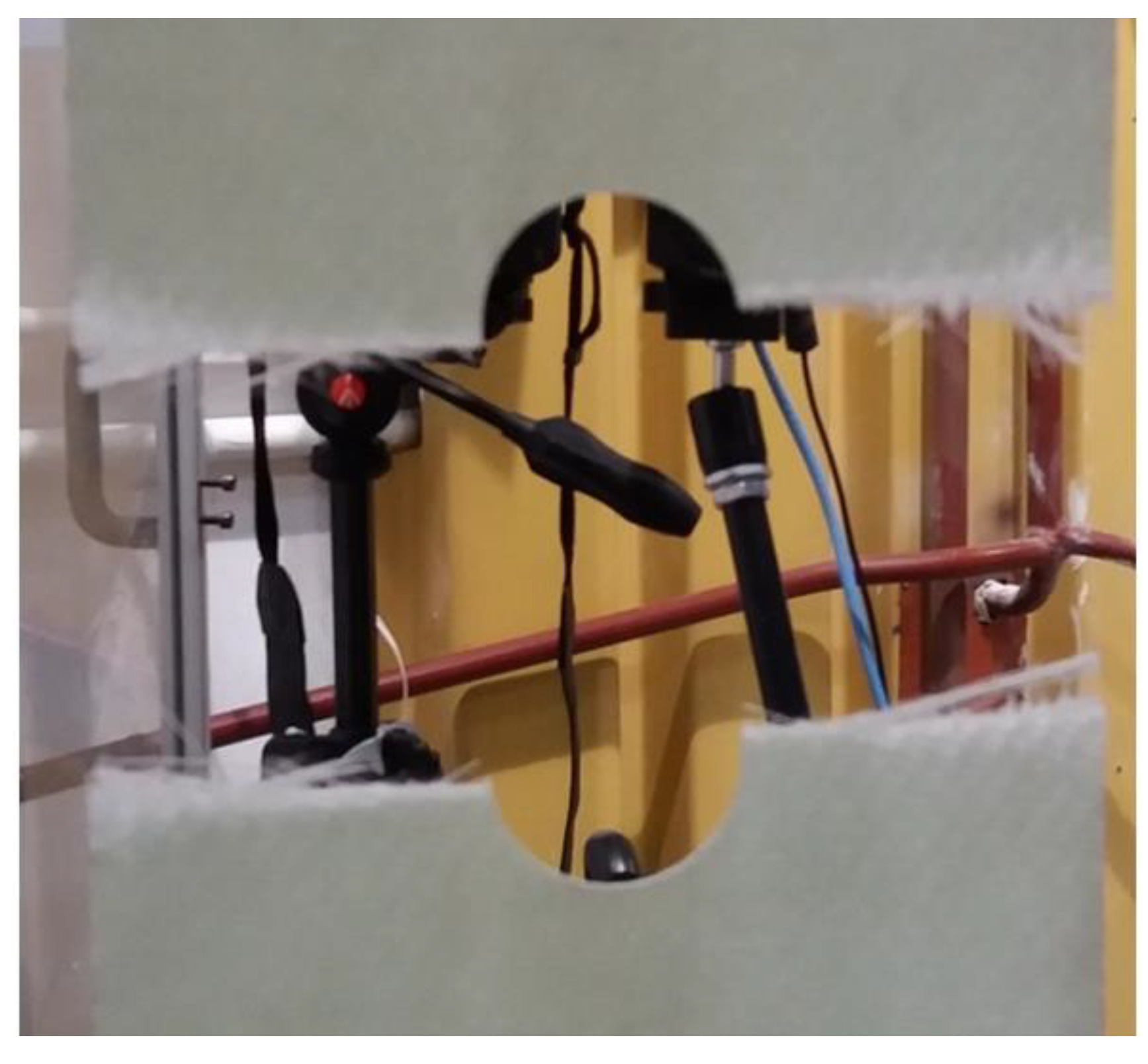
The typical fatigue final form is illustrated in
Figure 16. It is analogous to fatigue behaviour of isotropic (metallic) structures.
The number of cycles corresponding to the final fatigue failure are presented in
Table 3. They show the scatter of results caused by the nonuniform distributions of thicknesse for woven roving composites that have also a great influence on distributions of stresses along the specimen length – see
Figure 5.
The scatter of the critical number of cycles should be represented by the statistical or fuzzy set analysis – see the discussion presented by Muc [
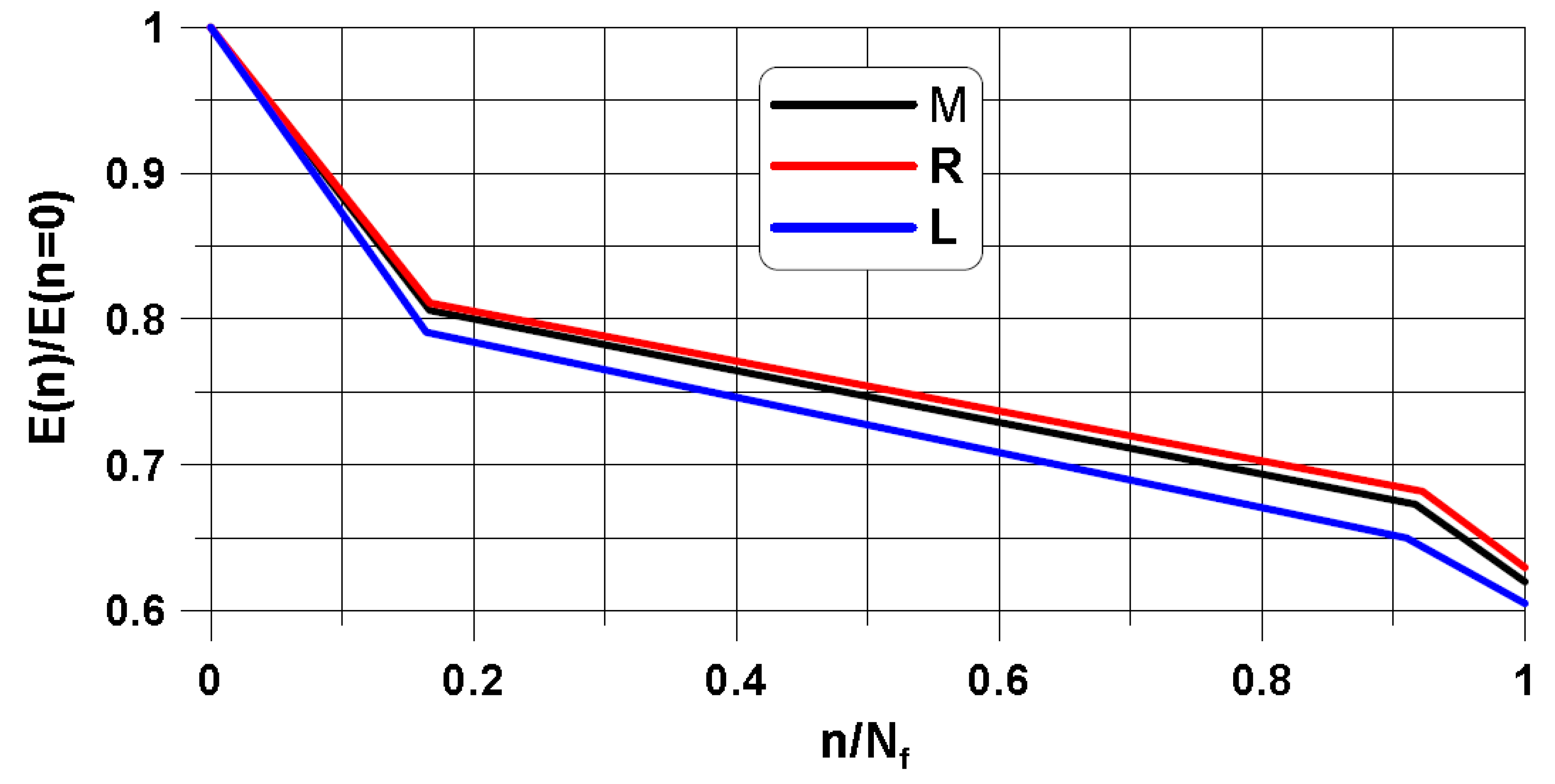
5]. Using the fuzzy set analysis the experimental fatigue degradation analysis (the decrease of the secant Young modulus) can be illustrated in the form drawn in
Figure 17. The results are represented in the form of straight lines being the approximation (linearization) of the experimental data.
In our opinion the results presented in
Figure 17 are much more convenient than the classical statistical analysis since it requires less of experimental data.
4.3. Finite Element Analysis
For low cycle fatigue problems the numerical modeling is carried out in two steps:
Finite element modeling of structures with convex holes
Derivation of final number of cycles using the Coffin, Manson relation (5)
The analysis is conducted with the use of the numerical package NISA II Endure version 17.
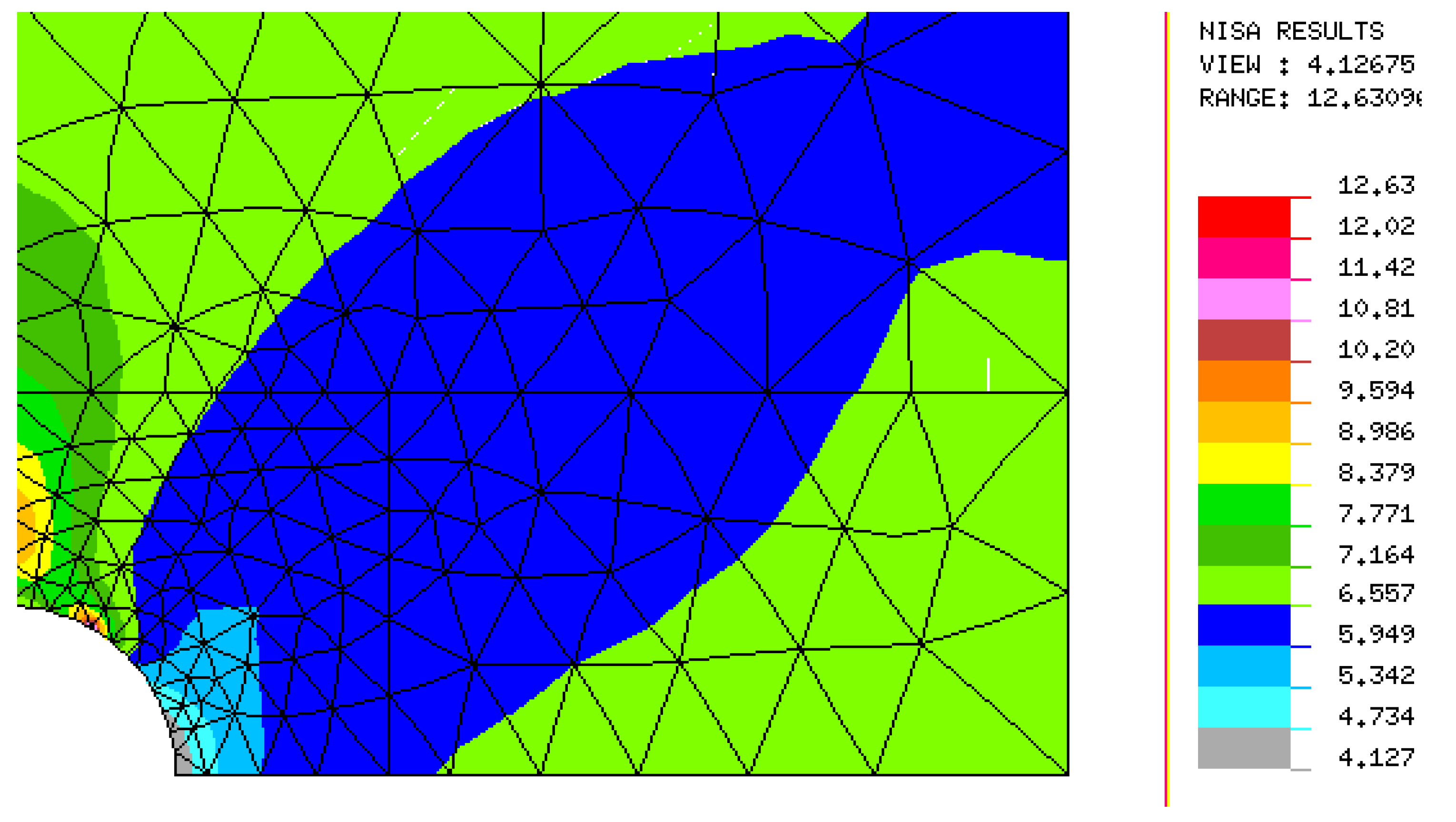
The lowest value occurs at the tip of the circular notch (the grey colour – see
Figure 18) and it corresponds to the experimental value –
Table 2. The crack initiation is always characterized by the lowest value of the number of cycles. The maximal value of N
f exists in the direction of the remote tension – the axis y.
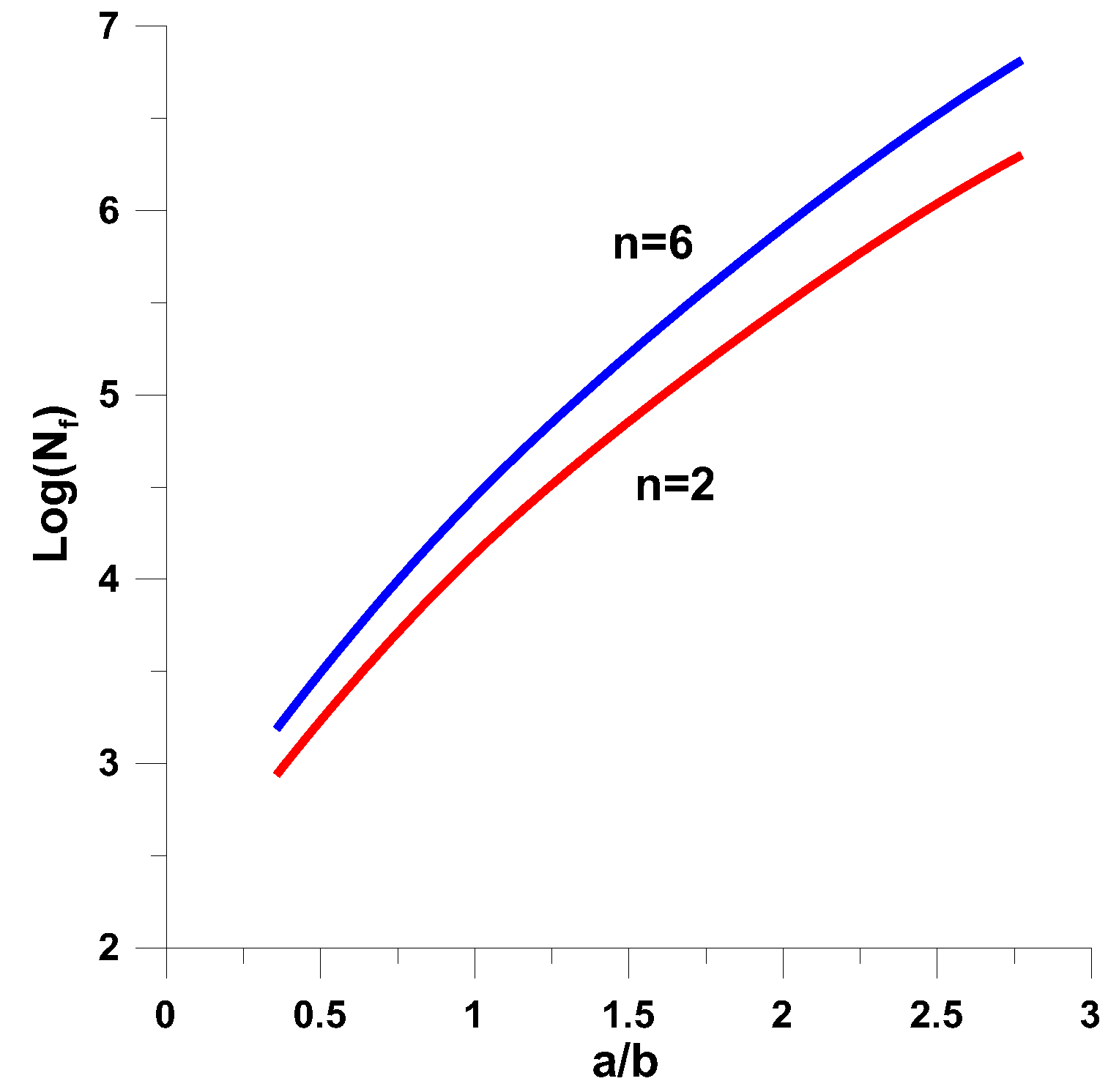
For different shapes of central notches the identical numerical analysis can be repeated. The results are illustrated in
Figure 19. As it may be seen the distributions are almost identical to the curves plotted in
Figure 11 describing the stress concentration effects for static loads.
Similarly as for the stress concentration factors the increase of the parameters a/b and n results in the increase of the critical number of cycles.
5. Conclusions
The influence of notches in 2D woven fabric composites is investigated in the mesoscale based on the ultimate stress and on fatigue loads. The stress/strain concentration under static and fatigue loads in 2D woven fabric composites with holes is influenced by the tensile loading direction and by the hole geometry and its dimension relative to the unit cell of the plain woven fabrics. For different shape parameters the strain concentration is located at the tip of holes.
The fatigue load behaviour is described by the low fatigue cycle method that is described herein.
The 2D woven roving composites have nonlinear behaviour and it has a significant influence on the final failure of static and fatigue failure. It results in the necessity of the use of statistical and fuzzy methods.
The computational finite element methods are also implemented in the paper. The comparison of experimental and numerical results is very good.
The presented results show the necessity of the use of at least two parameters (convex hole) to compare the static and fatigue behaviour of plates subjected to tension. The growth of the parameters a/b and n leads to the increase of the critical values characterizing the static and the LCS fatigue failure.
6. The novelty of the paper
The form of the convex holes can be approximated by two-parametrical description, i.e. the a/b ratio and the parameter n
The mesoscale analysis is sufficient for the characterization of static and low fatigue cycles failure damage – the comparison is presented with the use of FE and experimental analysis
The scatter of the experimental results is characterized by the fuzzy set analysis
Acknowledgment
The author would like to thank Dr H. Jodłowski, Dr P. Kędziora, Dr Z. Krawiec for their help in the preparation of the experiments.
References
- Muc, A., Effectiveness of optimal design with respect to computational models for laminated composite structures weakened by holes, (1998) Structural Optimization, 16 (1), pp. 58-67. [CrossRef]
- Muc, A., Ulatowska, A., Local fibre reinforcement of holes in composite multilayered plates (2012) Composite Structures, 94 (4), pp. 1413-1419.
- Muc, A., Romanowicz, P., Effect of notch on static and fatigue performance of multilayered composite structures under tensile loads (2017) Composite Structures, 178, pp. 27-36.
- Pandita S.D.,Nishiyabu, K., Verpoest I., 2003, Strain concentrations in woven fabric composites with holes, Composite Structures, 59, 361–368. [CrossRef]
- Muc, A., Fuzzy approach in modeling static and fatigue strength of composite materials and structures, (2019) Neurocomputing. [CrossRef]
- Bogdanovich, A. E., Pastore, C.M. (Eds), 1996, Mechanics of Textile and Laminated Composites, Chapman and Hall, London.
- Naik, N.K., 1994, Woven Fabric Composites, Lancaster-Basel, Technomic.
- Tong, L., Mouritz, A.P., Bannister, M.K., 2002, 3D Fibre Reinforced Polymer Composites, Amsterdam-Boston, Elsevier.
- Design and Manufacture of Textile Composites, 2005, Woodhead Publishing Ltd., Cambridge.
- Composite Forming Technologies, 2007, Woodhead Publishing Ltd., Cambridge.
- Boisse, P. (edt), 2011, Composite Reinforcement for Optimum Design, Woodhead Publishing Ltd., Oxford.
- Lomov, S.V (edt), 2011, Non-crimp Fabric Composites: Manufacturing Properties and Applications, Woodhead Publishing Ltd., Oxford.
- Blokley, R., Shyy W., (Edts), 2010, Encyclopedia of Aerospace Engineering, John Wiley & Sons, Ltd., Chichester.
- H. Altenbach, A. Ochsner, Encyclopedia of Continuum Mechanics, 2020, Springer Verlag.
- Kadir Bilisik, Nesrin Sahbaz Karaduman, Nedim ErmanBilisik, Fiber Architectures for Composite Applications, 2017, Elsevier.
- Sanjay Mavinkere Rangappa, Jyotishkumar Parameswaranpillai, Suchart Siengchin, Sabu Thomas, Handbook of Epoxy/FiberComposites 2022, Springer Verlag.
- S. Gohari, S. Sharifi, C. Burvill, S. Mouloodi, M. Izadafir, P. Thissen, Localized failure analysis of internally pressurized laminated ellipsoidal woven GFRP composite dome: Analytical, numerical, and experimental studies, Archives of Civil and Mechanical Engng. , 19, 2019, pp. 1235-1250.
- Y. Wang, X. Dai, K. Wei, X. Guo, Progressive failure behaviour of composite flywheels stacked from annular plain profiling woven fabric for energy storage, Composite Structures, 194 (2018), pp. 377-387.
- P. Potluri, S. Sharma, R. Rangulam, Comprehensive drape modeling for moulding 3D textile performs, Composites: Part A 32 (2001), pp. 1415-1424.
- S. Sharma, M. P. F. Sutcliffe, A simplified finite element model for draping of woven material, Composites: Part A 35 (2004) pp. 637-643. [CrossRef]
- Galletly G.D., Muc A., Buckling of fibre-reinforced plastic-steel torispherical shells under external pressure, (1988) Proceedings of the Institution of Mechanical Engineers, Part C: Journal of Mechanical Engineering Science, 202 (6), pp. 409-420.
- A. Muc, On the buckling of composite shells of revolution under external pressure (1992) Composite Structures, 21 (2), pp. 107-119.
- V. Divse, D. Marla, S.S. Joshi, Finite element analysis of tensile notched strength of composite laminates, Compos. Struct. 255 (2021) 112880. [CrossRef]
- B. Castanié, V. Achard, C. Chirol, Effect of milled notches on the strength of open hole, filled holes, single and double lap shear CFRP tension coupons, Compos. Struct. 254 (2020) 112872. [CrossRef]
- L. Wan, Y. Ismail, Y. Sheng, K. Wu, D. Yang, Progressive failure analysis of CFRP composite laminates under uniaxial tension using a discrete element method, J. Compos. Mater. (2020) 808840594. [CrossRef]
- A. Khechai, A. Tati, B. Guerira, A. Guettala, P.M. Mohite, Strength degradation and stress analysis of composite plates with circular, square and rectangular notches using digital image correlation, Compos. Struct. 185 (2018) 699–715. [CrossRef]
- T. Flatscher, M. Wolfahrt, G. Pinter, H.E. Pettermann, Simulations and experiments of open hole tension tests – Assessment of intra-ply plasticity, damage, and localization, Compos. Sci. Technol. 72 (2012) 1090–1095.
- E. Abisset, F. Daghia, P. Ladevčze, On the validation of a damage mesomodel for laminated composites by means of open-hole tensile tests on quasi-isotropiclaminates, Composites A 42 (2011) 1515–1524.
- G. Sun, L. Wang, D. Chen, Q. Luo, Tensile performance of basalt fiber composites with open circular holes and straight notches, Int. J. Mech. Sci. 176 (2020) 105517. [CrossRef]
- C. Hwan, K.H. Tsai, W. Chen, C. Chiu, C.M. Wu, Strength prediction of braided composite plates with a center hole, J. Compos. Mater. 45 (2011) 1991–2002. [CrossRef]
- R.S. Kumar, M. Mordasky, G. Ojard, Z. Yuan, J. Fish, Notch-strength prediction of ceramic matrix composites using multi-scale continuum damage model, Materialia 6 (2019) 100267. [CrossRef]
- M.M. Chauhan, D.S. Sharma, Stresses in finite anisotropic plate weakened by rectangular hole, Int. J. Mech. Sci. 101–102 (2015) 272–279. [CrossRef]
- J. Guo , W. Wen , H. Zhang , H. Cui, Influence of notch shape on the quasi-static tensile behavior of 2.5D woven composite structure, Thin-Walled Structures 165 (2021) 107944. [CrossRef]
- J. Song, W. Wen, H. Cui, Y. Wang, Y. Lu, W. Long, L. Li, Warp direction fatigue behavior and damage mechanisms of centrally notched 2.5D woven composites at room and elevated temperatures, Composites Science and Technology, 182 (2019), 107769. [CrossRef]
- S. Dai, P.R. Cunningham, S. Marshall, C. Silva, Open hole quasi-static and fatigue characterisation of 3D woven composites, Compos. Struct. 13 (2015) 1765–1774. [CrossRef]
- J. Song, L. Liu, L. Li, H. Zhou, W. Zhou, X. Li, et al., Thermo-mechanical responses of notched layer-to-layer 3D angle-interlock woven composites, Composites B 176 (2019) 107262. [CrossRef]
- L. Shuangqiang, Z. Qihong, C. Ge, F. Ko, Open hole tension and compression behavior of 3D braided composites, Polym. Compos. 41 (2020) 2455–2465. [CrossRef]
- M. Arshad, Damage Tolerance of 3D Woven Composites with Weft Binders, The University of Manchester, Manchester, 2014, pp. 109–130.
- M.N. Saleh, Y. Wang, A. Yudhanto, A. Joesbury, P. Potluri, G. Lubineau, et al., Investigating the potential of using off-axis 3D woven composites in composite joints’ applications, Appl. Compos. Mater. 24 (2017) 377–396. [CrossRef]
- Muc, A., 2003, Mechanics of fibrous composites, 2003, Kraków, (in Polish).
- Liang Wan, Jiayi Wu, Chuanyong Chen, Chuanxiang Zheng, Biao Li, Sunil Chandrakant Joshi, Kun Zhou, Progressive failure analysis of 2D woven composites at the meso-micro scale, Composite Structures 178 (2017) 395–405. [CrossRef]
- Muc A., Kędziora P., Application of fuzzy set theory in mechanics of composite materials, Soft Computing in Textile Sciences (editors L. Sztandera, C. Pastore), Springer-Verlag, 2001.
- Chwał, M, Muc, A., 2016, Transversely isotropic properties of carbon nanotube/polymer composites (2016) Composites Part B: Engineering, 88, pp. 295-300.
- M. Kaminski, F. Laurin, J.-F. Maire, C. Rakotoarisoa, E. Hémon, 2015, Fatigue Damage Modeling of Composite Structures: the ONERA Viewpoint, Life Prediction Methodologies for Materials and Structures, Journal of Aerospace Lab, Issue 9. [CrossRef]
- Ozturk, A., Moore R. E., 1992, Tensile fatigue behaviour of tightly woven carbon/carbon composites, Composites, 23(1), 39–46. [CrossRef]
- Xiao, J, Bathias, C., 1994, Fatigue behaviour of unnotched and notched woven glass/epoxy laminates, Composites Science and Technology, 50, 141–148. [CrossRef]
- Williams, J. C., Yurgatis, S. W., Moosbrugger, J C, 1996, Interlaminar shear fatigue damage evolution of 2-D carbon-carbon composites, Journal of Composite Materials, 30(7), 785–799. [CrossRef]
- Kawai, M., Morishita, M., Fuzi, K, Sakurai, T., Kemmochi, K., 1996, Effects of matrix ductility and progressive damage on fatigue strengths of unnotched and notched carbon fibre plain woven roving fabric laminates, Composites – Part A: Applied Science and Manufacturing, 27A, 493– 502. [CrossRef]
- Khan, Z., Al-Sulaiman , F S., Farooqi J K, 1998, Fatigue damage characterization in plain weave carbon–carbon fabric reinforced plastic composites, Journal of Reinforced Plastics and Composites, 17(15), 1320–1337. [CrossRef]
- Xiao, J, Bathias, C.,, 1994, Fatigue damage and fracture mechanism of notched woven laminates, Journal of Composite Materials, 28(12), 1127–1139. [CrossRef]
- Fujii, T., Shina, T., Okubo, K., 1994, Fatigue notch sensitivity of glass woven fabric composites having a circular hole under tension/torsion biaxial loading, Journal of Composite Materials, 28(3), 234–251. [CrossRef]
- Muc, A., Introduction to mechanics of composite materials and structures, (2020), J. Composite Sciences, 4, 1055705.
- Coffin L.F., Jr, A Study of the Effects of Cyclic Thermal Stresses on a Ductile Metal,Trans. ASME, 76, 931-950, 1954.
- Manson S.S., Behavior of Materials under Conditions of Thermal Stress, NASA TN-2933, 1953.
Figure 1.
Types of 2-D woven roving composites.
Figure 1.
Types of 2-D woven roving composites.
Figure 2.
Textile 2D woven fabric (plain weave).
Figure 2.
Textile 2D woven fabric (plain weave).
Figure 3.
Static strength of rectangular specimens made of woven roving composites (plain 2D glass) for different warp orientations.
Figure 3.
Static strength of rectangular specimens made of woven roving composites (plain 2D glass) for different warp orientations.
Figure 4.
Cross-sections of the unit cell for plain 2D glass composites.
Figure 4.
Cross-sections of the unit cell for plain 2D glass composites.
Figure 5.
Failure modes of 2D woven roving composites subjected to tension.
Figure 5.
Failure modes of 2D woven roving composites subjected to tension.
Figure 6.
Distributions of the stresses (the vertical axes warp, the horizontal axes weft– the width) – the force 11.25 [kN] – see [
5].
Figure 6.
Distributions of the stresses (the vertical axes warp, the horizontal axes weft– the width) – the force 11.25 [kN] – see [
5].
Figure 7.
Shape of the supercircle for different values of n (the constant area).
Figure 7.
Shape of the supercircle for different values of n (the constant area).
Figure 8.
The geometry of the specimens subjected to the uniaxial tension.
Figure 8.
The geometry of the specimens subjected to the uniaxial tension.
Figure 9.
Final failure of specimens subjected to uniaxial tensile load – woven roving glass.
Figure 9.
Final failure of specimens subjected to uniaxial tensile load – woven roving glass.
Figure 10.
Distributions of dimensionless the Huber-Mises-Hencky stresses for n=2 and the constant area Ac.
Figure 10.
Distributions of dimensionless the Huber-Mises-Hencky stresses for n=2 and the constant area Ac.
Figure 11.
Variations of the stress concentration around convex hole for constant area Ac.
Figure 11.
Variations of the stress concentration around convex hole for constant area Ac.
Figure 12.
ε-Nf curve – elastic and plastic strain curves.
Figure 12.
ε-Nf curve – elastic and plastic strain curves.
Figure 13.
Stress-strain curves for LCF.
Figure 13.
Stress-strain curves for LCF.
Figure 14.
Strain life ε-N curve.
Figure 14.
Strain life ε-N curve.
Figure 15.
Fatigue tensile load distributions.
Figure 15.
Fatigue tensile load distributions.
Figure 16.
Fatigue failure modes of stretched plates made of woven roving glass/epoxy – circular hole [
3].
Figure 16.
Fatigue failure modes of stretched plates made of woven roving glass/epoxy – circular hole [
3].
Figure 17.
The degradation of the stiffness for 2D woven roving composites (M – the average value, R – the highest value treated as the upper bound, L – the lowest value treated as the lower bound).
Figure 17.
The degradation of the stiffness for 2D woven roving composites (M – the average value, R – the highest value treated as the upper bound, L – the lowest value treated as the lower bound).
Figure 18.
Fatigue crack initiation life contours (the logarithmic scale).
Figure 18.
Fatigue crack initiation life contours (the logarithmic scale).
Figure 19.
Variations of the critical number of cycles Nf around convex hole for constant area Ac.
Figure 19.
Variations of the critical number of cycles Nf around convex hole for constant area Ac.
Table 1.
Static mechanical properties of plain 2D glass.
Table 1.
Static mechanical properties of plain 2D glass.
| |
Young’s modulus in the warp (longitudinal) direction linear part of the curves plotted in Figure 3a in [GPa] |
Young’s modulus in the weft (transverse) direction [GPa] |
Kirchhoff’s modulus linear part of the curves plotted in Figure 3b in [GPa] |
| Experimental |
13.142 |
13.004 |
9.621 |
| Finite Element modeling |
12.958 |
12.930 |
9.143 |
Table 2.
The comparison of the stress concentration effects for the ellipsoidal notches – the initiation of cracks.
Table 2.
The comparison of the stress concentration effects for the ellipsoidal notches – the initiation of cracks.
Stress Concentration
Factor |
Theoretical |
Numerical (FE) Analysis |
Percentage Error
|
| b/a=2.812 |
6.624 |
6.943 |
10.24 |
| b/a=1.000 |
3.000 |
3.211 |
12.51 |
| b/a=0.336 |
1.672 |
1.745 |
13.71 |
Table 3.
The critical number of cycles.
Table 3.
The critical number of cycles.
| Specimen |
1 |
2 |
3 |
4 |
| The length [mm] |
125.0 |
125.0 |
125.05 |
125.04 |
| The average thickness [mm] |
2.48 |
2.39 |
2.43 |
2.47 |
| Number of cycles Nf
|
11012 |
10945 |
15004 |
14617 |
| Average number of cycles |
12894.5 |
|
Disclaimer/Publisher’s Note: The statements, opinions and data contained in all publications are solely those of the individual author(s) and contributor(s) and not of MDPI and/or the editor(s). MDPI and/or the editor(s) disclaim responsibility for any injury to people or property resulting from any ideas, methods, instructions or products referred to in the content. |
© 2023 by the author. Licensee MDPI, Basel, Switzerland. This article is an open access article distributed under the terms and conditions of the Creative Commons Attribution (CC BY) license (https://creativecommons.org/licenses/by/4.0/).
