1. Introduction
A Prosthetic is an artificial device to replace missing or lost limbs. These instances mainly contributed to amputation [
1]. Amputation is a surgical process to remove a segment of body parts. Infection, disease (related to the circulatory system), and traumatic events (falling, crushed, blasted). Different cases of amputation require a different type of prosthetic device based on the level of amputation. In general, a prosthetic can be classified as upper limb prosthetics and lower limb prosthetics. Upper limb prosthetics is a prosthetic meant to replace bodily parts above the hip (i.e., trans-radial and elbow disarticulation). On the contrary, lower limb prosthetics are meant to replace bodily parts below the hip (i.e., transtibial, transfemoral) [
2]. In prosthetic development, aesthetics and function are two parameters that cannot be separated. Therefore, the development of prosthetics has been extensively studied to provide a better solution for the amputee. The latest development in the field of prosthetics provides not only a primary function but, to some degree, return amputee to the lifestyles they were used to before amputation [
3].
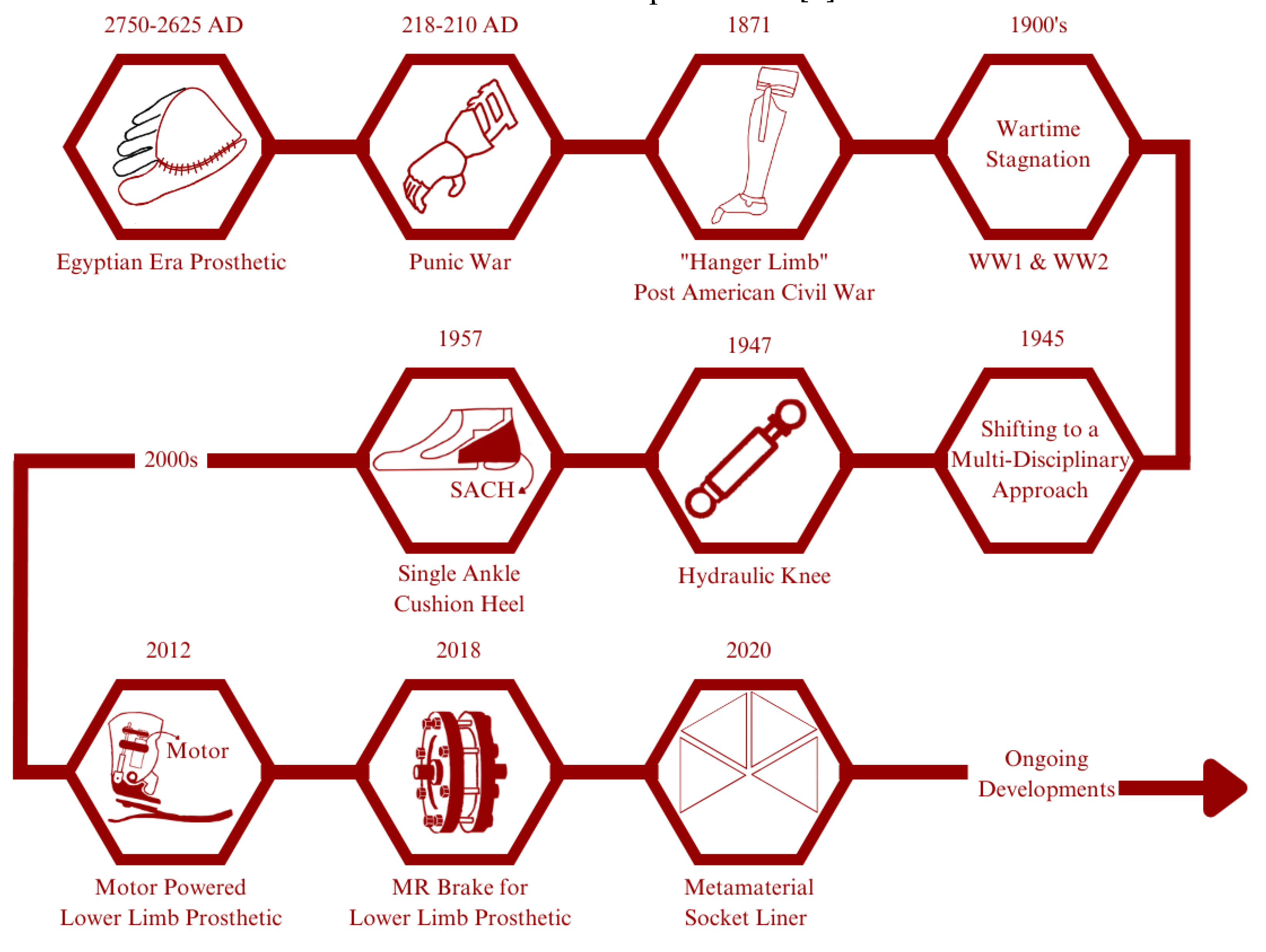
Egyptian civilization is known as the first pioneer of developing prosthetic devices dating from 2750-2625 AD. Their prosthetics are mainly made of fiber and used primarily for appearances rather than for its function; Some exception to this is a prosthetic finger found on an Egyptian mummy that is believed to provide a functional and non-functional purpose [
4]. Another instance in our history regarding the use or development of prosthetics is from the Punic War (218-210 AD), where there was a Roman soldier with an iron hand to replace his missing arm [
5]. The year 1871 sees a significant increase in amputation numbers following the conclusion of the American Civil War. James Edward Hanger developed an above-knee prosthetic (patented as “Hanger Limb”) with the implementation of a rubber bumper to replace the standard catgut tendons and designed with a hinge at the knee and ankle [
6]. Later major wars, like WW1 and WW2, did not see a significant advancement of prosthetic technology caused of the higher demands for the development of military technology. Later on, to solve this problem, in February 1945, the US National Academy of Sciences (NAS) initiated and planned a research and development (R&D) program aimed at developing prosthetic improvements by applying technology from other specialized fields. This event was soon followed by significant developments such as the first hydraulic knee in 1947, SACH (solid ankle cushion heel) introduced by Anthony Staros in 1957, a computer-aided robotic arm in 1980, and a motor-powered lower limb prosthetic in 2012 [
7]. Implementation of unique properties of MR (magnetorheological) effect as a brake for lower limb prosthetics [
8], and by 2020, Nathan Brown et al., conducted research to improve the comfort of amputees by proposing the use of metamaterials as a liner in socket for a transtibial prosthetic [
9].
Figure 1.
Historical Development of Prosthetic: In ancient Egypt, wooden prosthetic toes and feet were crafted for amputees. These prosthetics were not functional but were designed to mimic the appearance of a real foot or toe. Similarly, in ancient Greece and Rome, prosthetics were made from wood and bronze and were designed primarily for aesthetic purposes. In recent years, advancements in robotics and computer technology have led to the development of advanced prosthetic limbs that can be controlled using neural signals from the user’s brain. These “bionic” limbs are capable of incredibly lifelike movement and have revolutionized the field of prosthetics. The development of prosthetics has been a long and fascinating journey, with significant advancements being made over the centuries. Today, prosthetic technology continues to advance rapidly, offering new hope and possibilities for amputees around the world.
Metamaterial is derived from the Greek word “meta” which means “to be beyond.” Hence, Metamaterial is defined as a unique material with effective properties that is beyond its conventional counterparts. Effective Properties of Metamaterial originated from its bulk material properties and structural arrangement or design. These Effective Properties are varied based on the class of the Metamaterial and its purpose. Mechanical, acoustic, electromagnetic, and thermal Metamaterial are the four general classes of Metamaterial. Mechanical Metamaterial, also known as Auxetic Metamaterial, are Metamaterials exhibiting the unique property of Negative Poisson’s Ratio (NPR) or the ability to laterally enlarge when longitudinally stretched. Lakes first studied this unique property in 1987 [
10], which was then coined as “Auxetic” to shorten the term “Having a Negative Poisson’s Ratio” by Evans et al. [
11]. The word Auxetic is also derived from the Greek meaning “growing” or “having the tendency to grow.” Since then, the concept of Auxetic Metamaterial has been extensively researched and keeps increasing even until now.
Early on, the research was mostly focused on developing better structure arrangement and analyzing its properties (i.e., Poisson’s ratio, effective modulus, stiffness, and energy absorption). In terms of its structural arrangement, unique geometries are based on a re-entrant hexagon [
12], double-V [
13], double-U [
14], chiral [
15], and even major changes to the already established re-entrant hexagon by adding and additional horizontal component between the vertical parts [
16]. Lately, the focus of research in the field of Auxetic has gradually shifted to a more practical approach. These researches include an Auxetic nail [
17], an anti-blast and anti-impact protection [
18], an Auxetic stent for circulatory disease [
19], an Auxetic implant [
20], and an improvement in foot prosthetic performance [
21].
In this review, we provide recent state-of-the-art research in the field of prosthetics and discuss how Auxetic Metamaterial could provide a more expansive improvement for later research. First, this review will provide the general concept of Auxetic Metamaterial and its unique NPR property. Then this review will also report on the latest research and development of prosthetics, accompanied by a comparative discussion about its advantages, disadvantages, and limitations. Lastly, in this review, we will discuss the future prospects of Auxetic implementation for a prosthetic.
2. State of the Art
The research of metamaterials development has been gradually shifting. The earlier research focuses mainly on developing and understanding relevant mechanical properties of novel metamaterial shapes and geometries. The number of metamaterial research in practical and applicative approaches has been increasing in the last three years. This condition also applies to the practical research of prosthetic devices. In this section, we will provide an overview of state-of-the-art research with the implementation of auxetic metamaterials as its primary focus.
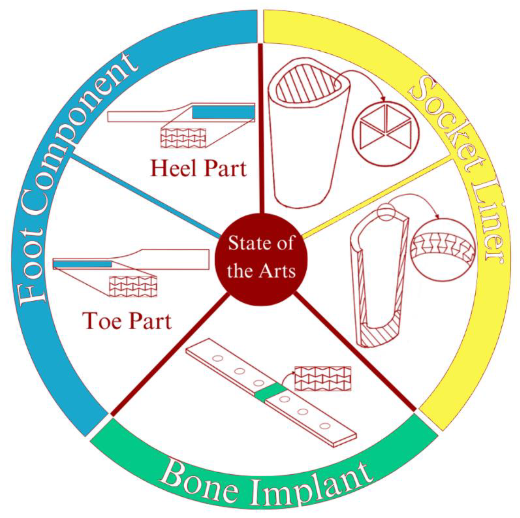
Figure 2 illustrates the state-of-arts described in this section.
Existing research mainly covers the use and application of lower limb prosthetics due to its high and increasing demands [
22]. A common problem concerning lower limb prosthetics usually relates to the comfort of its user [
23,
24,
25]. There has been an effort to solve this problem, including research investigating the use of auxetic metamaterial inlay to improve the stress distribution associated with the residual limb for transtibial prosthetics [
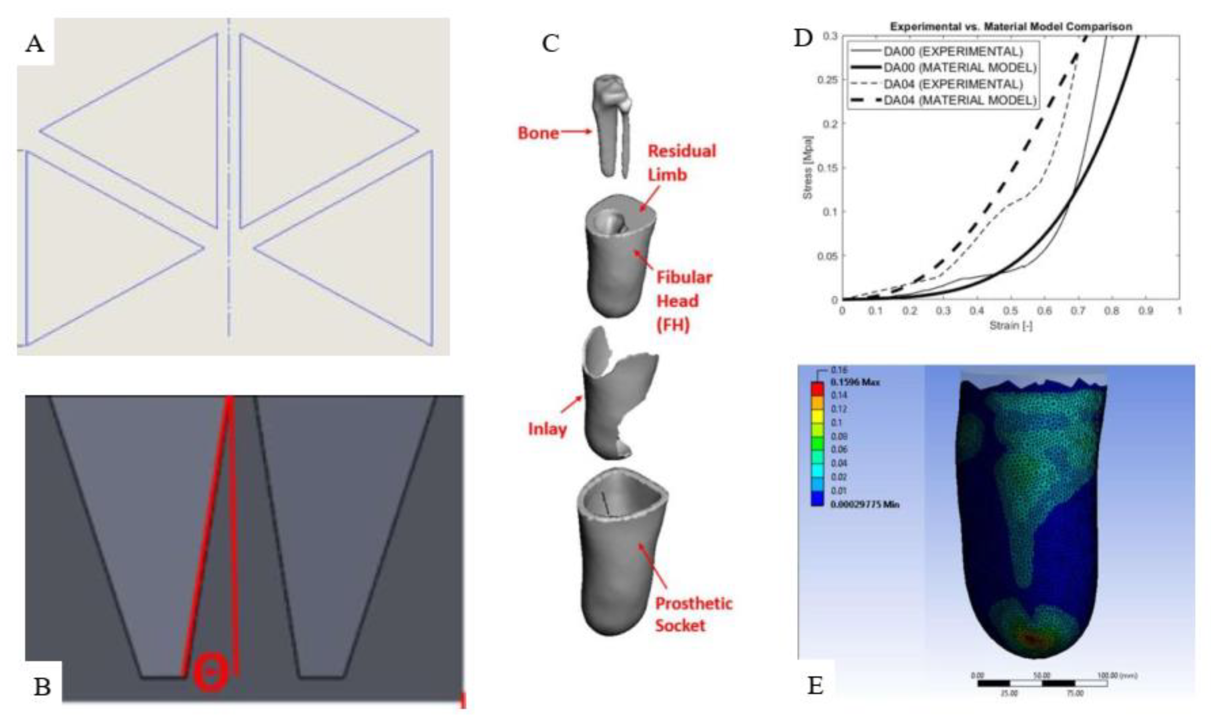
9]. The metamaterial structure implemented in this instance is based on orthogonally patterned equal-sized triangles repeated four times spanning 180 degrees with uniform gaps. The structures are additively manufactured using a 3D printer and “TangoPlus” as the base material. This research analytically investigates the aspects of PS (Peak Stress) and PPG (Peak Pressure Gradient) with the structure’s wall draft angle variation using the Finite Element Analysis (FEA) method. Comparison and optimizations of each result are discussed to provide a better pressure distribution using metamaterial inlay. In conclusion, this research is an example of metamaterial implementation on transtibial prosthetics to improve comfort by reducing PS and PPG.
In order to provide an accurate representation of material behavior, a material model is needed. For this case, the author has chosen to use the Yeoh 3rd order representation [
26]. Yeoh 3rd order representation describes the behavior of materials with large deformation under loading. C
i0 defines the three material coefficient of each material base composite material, while
and
defines stress and strain produced respectively. The mathematical model for this is as follows:
Another research presents a solution for transfemoral amputees by implementing metamaterial in the socket between the inner lining and outer shell [
27]. This research also considers the socket’s deformability to improve comfort for amputees by ensuring a sure fit with the residual limb. For this application, a basic re-entrant hexagon honeycomb is designed radially to outline the prosthetic socket’s inner lining. As a purely FEA-based research, there is no mention of fabrication methods in this article. The material is modeled after the properties of Polyurethane for the inner lining part, as for the outer shell and metamaterial structure are modeled as carbon fiber-reinforced nylon. While the socket dimension was based on the average size of human thigh data.
The solution for the FEM problem was based on Navier’s equation of motion. The mathematical model for the problem is written as follows:
FEA tool used for this investigation was Solidworks. The results are divided into four investigations. The first two relate to the capability of the socket in supporting a given load. The first was for the static condition of loading the full body weight of the user (standing by one leg) which was assumed to be 70 kg (700 N). The second one was focused into investigating the performance of the socket while the user is in gait. This condition was modeled by applying a given impact force during gait (for a 70 kg user, the impact force is assumed to be 980 N (1.4x body weight)).
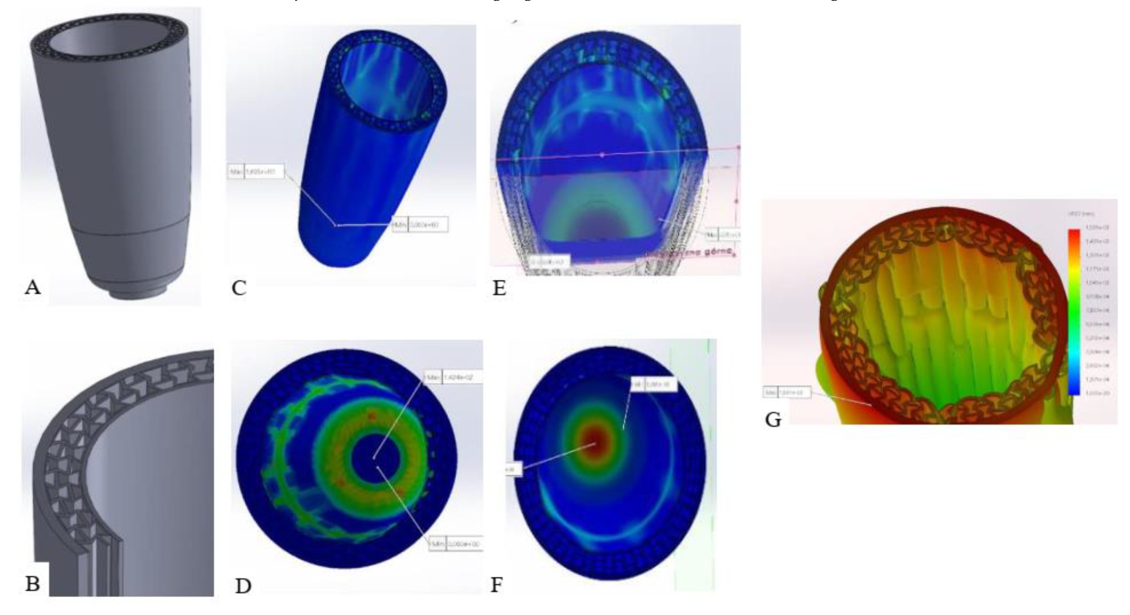
The analysis of force acting from the residual limb toward the inner circumferential surface of the inner lining of the model. This type of load caused a stretching deformation to the inner lining. Although for 70 kg user, the circumferential force acting would be considerably lighter than 700 N, this number could also quantify as a form of safety factor and to also provide better visualization for the effect of the swelling. For the last simulation case, an external force acting on the surface of the outer shell is modeled and investigated. This case is to simulate a condition in which a user chose to push in the outer shell when wearing a slightly loose socket after inserting the residual limb. Based on the average data of force exerted from one hand is equal to 250 N, with the assumption of the user pushing with both hands, the applied force becomes 500 N. As a result, this research shows that the socket fulfills its strength requirements while also providing additional adjustment to the changing size of the residual limb through the auxetic effects.
Figure 4.
Implementation of auxetic metamaterial for the interface of a transfemoral prosthetic. (A). Shows the external view of the interface part, consisting of outer shell, metamaterial structure, and inner lining. (B). Shows the metamaterial structure connecting the inner lining and the outer shell. The structure is modeled after the re-entrant hexagon arranged radially and carbon fiber reinforced nylon as the material. (C,D). Shows the resulting view of the case of the simulation for the user statically standing by one leg. (C). For its, von Misses stress distribution (maximum reduced stress present on the lower part of the socket with 1.695 MPa of stress), while (D). for its deformation distribution (maximum deformation for the applied force is 1.42 mm). (E,F). Shows the results for the case of walking user. (E). For the stress distribution (with the maximum value exceeding 2 MPa, which is still lower than the strength of the material modeled) and (F). for the displacement distribution (the maximum displacement does not exceed 4 mm). Lastly, (G). shows the result for the case of an external force acting on the outer shell. For this case, the maximum stress occurring is 0.27 MPa.
Another way to develop a prosthetic is by improving energy absorption. Such is the research conducted in 2021 to give the prosthetic the unique behavior for the heel part of the foot prosthetic [
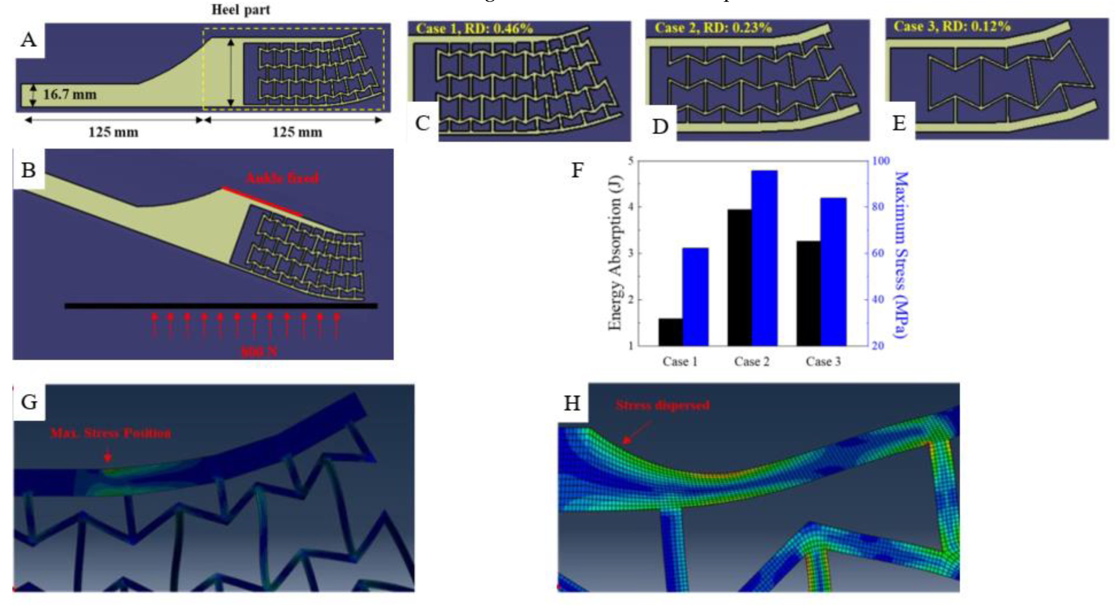
21]. This improvement is aimed at providing better energy absorption during the heel strike. This research provides an example of yet another practical research for a prosthetic device that uses the basic re-entrant hexagon as the metamaterial structure. Onyx is used as the base material for the model simulation. The proposed design was based on the re-entrant hexagon geometry which is modeled on the heel part of the foot. The variation for the design parameter is based on the Relative Density (RD) of the overall structure applied. RD itself denotes the ratio of all the lattice structure (A) to the area of the unit cell (As) or written as follows:
To better investigate the energy absorption capabilities of the proposed design. A comparison was made for the variation of three different cases of RD. With the RD of 0.46, 0.23, and 0.12, respectively for case 1-3. The foot model was designed as a 2D surface model and meshed with CPE4R elements. The modeled foot dimension was based on the dimension of a custom-built prosthetic from a past study (AMPRO II). The total length of the foot was 250 mm, the height of the toe part was 63 mm, while the heel part was 125 mm. The force-integral method was used to define the energy absorption (W) capabilities of each case mentioned. This method works by integrating the Ground Force Reaction (GRF) denoted as F, over the deformation (S). The force-integral method could then be written as [
27]:
In conclusion, this research shows the potential of implementing auxetic metamaterial for shock-absorbing function in lower limb prosthetics.
Figure 5.
The use of auxetic materials in prosthetics for the heel part of the foot. The auxetic metamaterial structure was based on the re-entrant hexagon and designed to be located on the heel part of the foot with the overall dimension as visualized on (A). The boundary and simulation condition (B) are described as the foot positioned a certain degree in relative to the ground, while the ankle equivalent is fixed. The model investigated is divided into three categories based on its RD, with the value of 0.46 for case 1 (C), 0.23 for case 2 (D), and 0.12 for case 3 (E). Figure (F) shows the comparison of simulation results in regard to the energy absorption and maximum stress in each case. From this result, it can be concluded that the case to shows the most promising design for absorbing energy; this, however, is also entailed with the condition of having the highest maximum stress compared to the other two cases. The high value of maximum stress was caused by a stress concentration occurring in the middle part of the upper plate (G). To alleviate this problem, a rounded shape is proposed as shown in (H). This solution has proven to be effective as the maximum stress for the rounded shape design has been reduced to 37.92 MPa (within the boundary of onyx yield strength of 36 MPa).
Later on, the same author conducted another research focused on providing an additional mechanism to the lower limb prosthetic [
29]. This innovation is located at the toe part of the prosthetic to bring a unique nonlinear stiffness behavior for the prosthetic. This research is important because of the low number of prosthetic development targeting an improvement on the toe part, the main focus usually being the mechanism on the heel part [
30,
31,
32]. Same with the earlier research, this one also uses the basic re-entrant geometry as the metamaterial structure and still using onyx as the modeled material. Compared to the earlier study, for this one, the relative density of the structure remains fixed at 0.4 (value based on calculation from Equation (2)). The variations were made by dividing the shape and the existence of bending space/bending zone (
Figure 6C,D).
For the methodology, the toe angle and toe torque are investigated and optimized to better mimic the natural behavior of the human toe. The prosthetic is inclined 25° relative to the ground. The ankle part remains constrained in place. 1000 N of force is applied in the direction normal to the inclined part to simulate the weight of an average human male with 100 kg of weight [
33]. The results of the proposed design were then compared with the toe-torque of humans during toe-off. The toe torque follows the below formula [
33]:
Non-dominated sorting genetic algorithm (NSGA-II) was used in this study to optimize the structure of the prosthetic foot. By using MATLAB, the condition was inputted to generate a model. This model is then simulated through ABAQUS. Based on the results provided from ABAQUS, it was inputted back to NSGA-II [
35]. This process is repeated until a solution converges. To further validate the performance of the proposed prosthetic, a comparison with human gait data was also conducted. Ground Reaction Force (GRF), center of pressure (COP), ankle angle, and ankle torque were gathered.
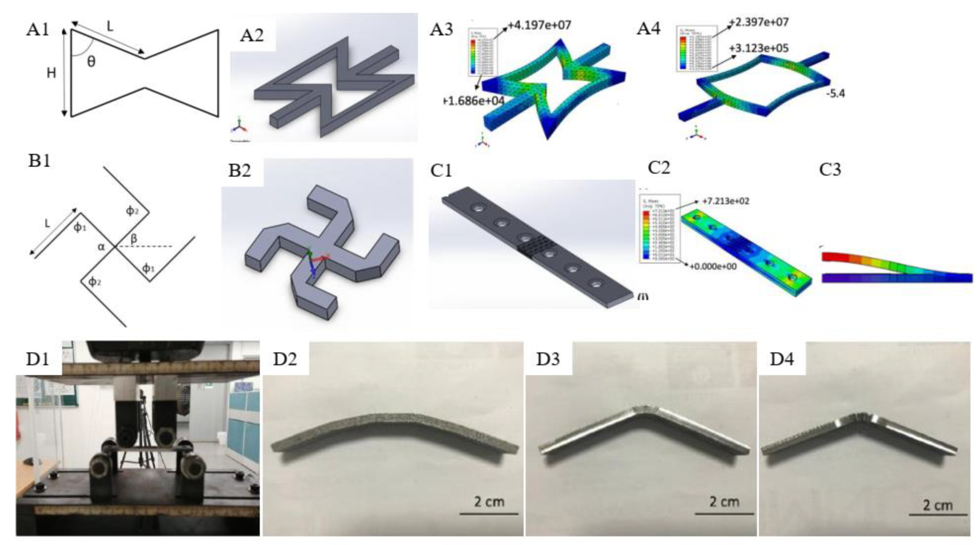
The field of lower limb prosthetics is not the only field of development where an auxetic metamaterial is potentially useful. For instance, another study developed orthopedic bone plates (a rehabilitation device used to repair fractured bones) [
36]. The use of auxetic metamaterial for this development is aimed at mitigating stress shielding and limiting the displacement of fractured bones during the healing phase. Basic re-entrant hexagon honeycomb and missing rib structures are analytically investigated using ABAQUS. For the re-entrant structure, an analytical model to define the Poison’s ratio used is as follows [
37]:
From the above model, a Taguchi Design of Experiments (DOE) method is used to provide the response of the model for given parameters. In this case, the parameters involved are H, L, and θ resulting in Poisson’s ratio as the response. Based on this design, a model was chosen to further study the effect of unit cell quantity towards the value of NPR. For the missing rib structure, the analytical model used to evaluate the Poisson’ ratio is formulated below [
38]:
After the structure has been formed, it was then used to model the bone plate using SolidWorks. The CAD was configured by modeling it based on the properties of Stainless Steel 316L, with a thickness of 3.6 mm, and width of 13.05 mm, and also featuring 6 screw holes with 16 mm of spacing. To optimize the positioning of auxetic structure on the bone plate, both experimental and finite element methods are used to decide the most optimal position for the auxetic structure. For this analysis, three model variations were investigated (control, re-entrant, and missing rib). Based on the model, a direct laser sintering (DMLS) is used for its fabrication process. DMLS itself is a form of 3D printing utilizing laser power to melt and print metal powder layer by layer based on CAD data sliced beforehand [
39,
40]. The specimen made are then tested based on the ASTM F-32 using INSTRON machine. With a loading rate of 1 mm/min. This experimental test would provide load-displacement data. This data is then derived to quantify the bending stiffness (K) of the bone plate. This was calculated from the maximum slope of the load-displacement data. Based on this data, the structural stiffness (or flexural rigidity) of the bone plate is formulated as:
The mentioned research works as state-of-the-art research conducted in the field of auxetic implementation for prosthetic devices. This shows that by implementing auxetic metamaterials, a new better innovation for prosthetics could be developed.
3. Poisson’s Ratio and Other Mechanical Properties
Siméon Denis Poisson first defined Poisson’s ratio as a measure of the tendency for a material to undergo a deflection perpendicular to the direction of an applied force. The equation which defines Poisson’s ratio is as follows (Equation (1)) [
41]:
Poisson’s ratio of a material is essential and often overlooked as a constant shared by many materials (which are assumed to have 0.3 Poisson’s ratio).
Table 1. provides a list of some common materials and corresponding Poisson’s ratio.
As could be seen from the above list, most common materials show a positive Poisson’s ratio with few exceptions. This exception either shows zero Poisson’s ratio, like found in cork [
46,
47], or negative Poisson’s ratio to some degree and includes some biomaterials like cat skin [
48,
49]. Materials exhibiting Negative Poisson’s Ratio (NPR) are also known as Auxetic. Although the example shown in
Table 1 is compromised by naturally occurring materials, artificially made materials known as Auxetic Metamaterials are the most commonly found material exhibiting auxetic behavior.
Auxetic metamaterials are made possible through artificially structuring material so that Poisson’s ratio is affected not only by its inherent properties but also by the structure design. Auxetic metamaterials commonly use re-entrant honeycombs geometry, such as re-entrant hexagons [
12], and chiral-based honeycombs, such as hexa-chiral [
15], and tri-chiral [
50].
In order to accurately quantify this number, there are some methods to measure the Poisson’s ratio of a given material experimentally. The most common way to measure this property is by measuring the deformation happening to a material from lateral and axial directions under tensile or compressive testing [
51,
52]. The FEA method can also be used to measure the Poisson’s ratio of the material with specific geometries, but this method requires the Poisson’s ratio of the bulk materials involved. The FEA method usually simulates the same boundary condition involved for the experimental method. This method is advantageous to measure the Poisson’s ratio of Auxetic Metamaterials, considering the difficulty of fabricating a specimen or sample to be tested experimentally.
Earlier research on Auxetic Metamaterials focused mainly on developing novel structure geometries. In this instance, to validate the performance of the structure, common properties being investigated include Poisson’s ratio, stress-strain curve, energy absorption, deformation behavior under loading, and stiffness. Next on will be a discussion regarding the above mechanical properties. Stress-strain curve defines the relationship between the stress and strain of a material or an object. From this curve, one can also envision deformation for any given stress. There are many ways to measure both the stress and strain of a material or object. The method usually consisted of experimentally applying a load to a specimen sample and measuring the stress (commonly by the use of a load cell) and strain (typically using an extensometer). The direction of the applied load differs depending on the data needed to be investigated—various methods used, such as tensile [
53,
54], compression [
55], flexural [
56], and impact [
57].
Understanding both stress and strain is essential because it directly affects the values of other mechanical properties such as strength, stiffness, and energy absorption. These properties are also important in the development of auxetic metamaterial. It depends on its development’s purpose and its relation with other properties. Most of the time, an auxetic metamaterial is characterized by high elasticity. This is mainly attributed to unique structure promoting gaps and voids, leading to lower stiffness value [
58]. This limits the role an auxetic metamaterial could be effectively used. Application in aerospace, automotive, structural or construction, and to some degree medical field requires materials with high stiffness.
Efforts have been made in numbers to solve this limitation. Various solutions including modifying the auxetic structure’s geometry or design parameter, adding filler to fill in the gaps of void, and combining different materials to enhance the stiffness. These instances show that enhancing auxetic metamaterials’ stiffness is possible. Though, there are limitations as to how far pushing the stiffness is viable and the downside of having the possibility to reduce the effect of NPR [
59]. Developing and studying auxetic metamaterial must take both limitations and downsides into consideration. Another point of interest when developing or researching auxetic metamaterials is studying how it deforms or also known as deformation behavior. Understanding the deformation behavior of auxetic metamaterial is essential to better predict its performance and how it would fail. The deformation behavior of an auxetic metamaterial could be investigated by using the FEA method to analyze the deformation. Combined with equivalent experimental testing, a DIC (digital image correlation) method could be effectively executed to compare both results [
60]. This comparison will provide a more accurate representation. There are instances when a unique deformation behavior of auxetic metamaterials makes it potentially useful for energy absorption [
61] and impact-resisting application [
62]. Auxetic metamaterials will inwardly contract when compressed. This leads to a higher concentration of materials at the point of contact [
63], attributing to enhanced energy absorption and capacity to resist impact.
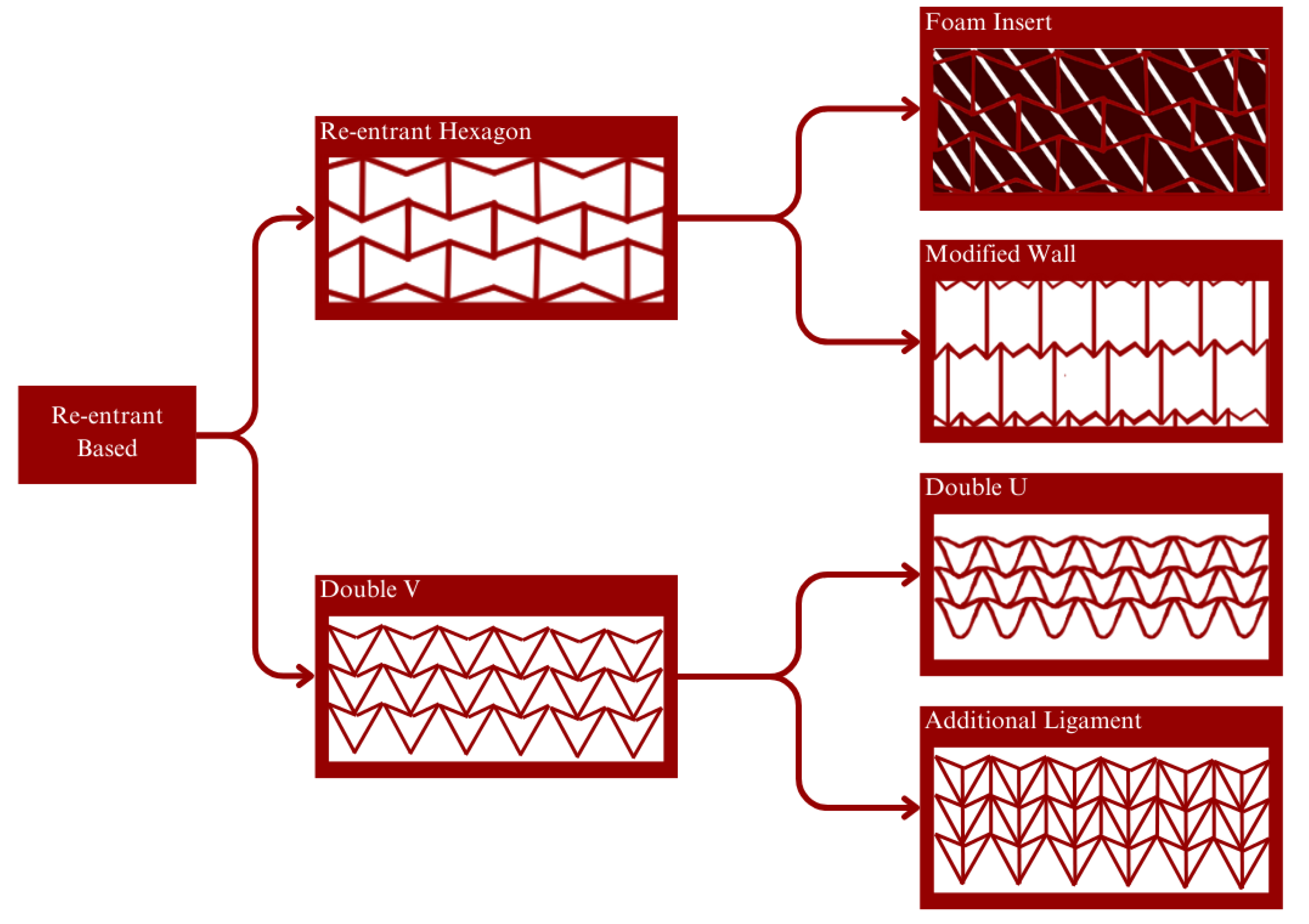
All the above properties mentioned are customizable depending on the structure or geometry it was designed. This happens because auxetic metamaterial properties are derived from its inherent material properties but also the geometry of the structure. The auxetic metamaterial’s geometry could be classified into re-entrant-based geometries, chiral-based geometries, and rotation-based polygon geometries. Re-entrant the phenomena of a polygon with vertice(s) that is pointing inward. The most common re-entrant geometry is the basic re-entrant hexagon or also known as the bow-tie hexagon. This type of geometry is able to exhibit a negative Poisson’s ratio behavior because its re-entrant aspect makes it so that when pulled, the vertice(s) pointing inward is prone to be pulled out when in tensile. While in compression, the inward vertice(s) is further pushed in.
The development of the re-entrant hexagon was oriented toward improving the stiffness properties. To achieve this, insert material could be used, such as foam. Another approach for the same objective would be to modify the geometry, such as the introduction of additional turning points [
64] or additional struts [
16]. Double V, also known as double arrowhead (DAH) geometry, as the name suggested, is based on the shape of the arrowhead [
65]. This geometry is also considered a re-entrant geometry because there is a single vertice that is pointing inward. Similar deformation behavior applies when being compressed and in tensile. The same with the re-entrant hexagon, improvement is made in terms of its stiffness by adding additional ligament [
66]. Double V is also developed into Double U to reduce the stress concentration made by its vertices [
14].
Figure 8 illustrates the development and improvement of re-entrant geometries.
Chirality is a condition in which an object cannot be superimposed on its mirror plane [
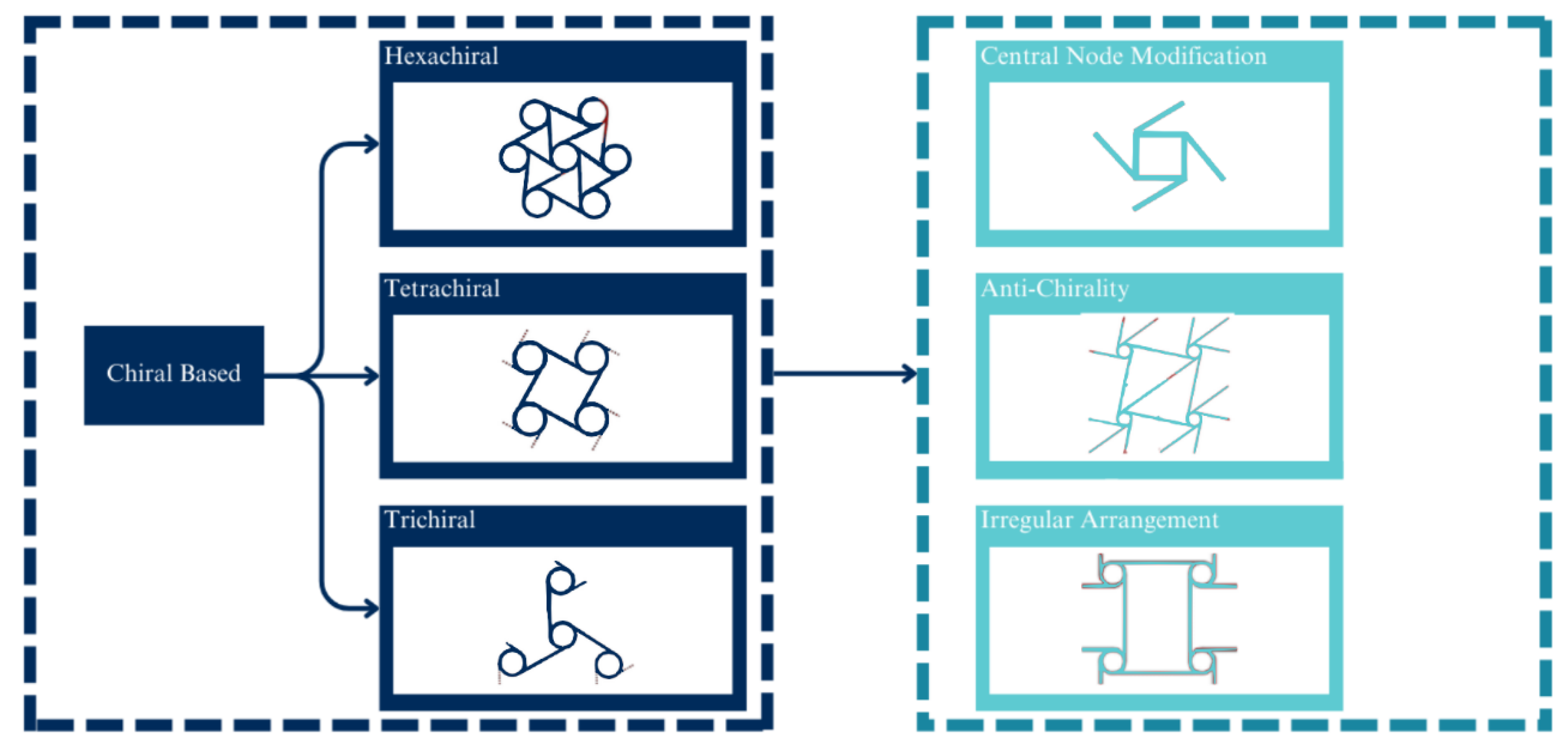
67]. Though recently, chiral metamaterials are made up of lattice geometry that is prone to spin or rotate around its central node [
68] when in compression or tensile. As mentioned, a chiral geometry consists of a central node and connecting ligament. The basic chiral structure is based on the number of connecting ligaments, such as the hexachiral (six ligaments) [
15], tetrachiral (five ligaments), and trichiral (three ligaments). A more recent development is focused on the derivation of these basic structures. These instances include the development of an anti-chiral structure, the investigation of the effect of irregularity and disorder [
69,
70,
71], and the modification of the central node or its ligaments [
72,
73].
Figure 9 illustrates the development and improvement of chiral-based geometries.
Rotating-based polygon differs from the other two lattice classes, which take advantage of thin beam-like parts or also known as a ligament, to connect the different parts of the structure. On a rotation-based polygon, the connection is made directly on the vertices of the cell. This connection works like a hinge that rotates (opens and closes) the cells based on the force applied [
74]. This class is subclassified based on its base geometry, such as rectangular [
75,
76], triangle [
77], and parallelogram [
78].
Figure 10 illustrates the different subclasses of the rotating-based polygon.
Early on, in this section, it was mentioned that the research and development of auxetic metamaterials have been mostly using the FEA method with some experimental testing with considerable limitations and required adjustments. ABAQUS, LS-DYNA, and ANSYS are commercially available FEA tools that have been used by earlier studies. To get a more accurate simulation result, the validation method used is to compare it with theoretical analysis, experimental testing, or past data from other documentaries.
Table 2 below lists the tools, base material model, and validation method of a combination of past studies regarding auxetic metamaterials.
4. Regarding Prosthetic
As mentioned on the introduction earlier, prosthetic is an artificial device to replace missing or lost limbs [
99]. These instances mainly contributed to amputation. Amputation is a process of disarticulating limbs or body parts. Common causes for amputations are diabetes, cancer, traumatic events, hypertension, hyperlipidemia, and in rare cases includes, congenital limb deficiencies [
100]. Diabetes is a disease caused by a drastic elevation in the blood sugar level in the circulation system. This condition often leads to damage to blood vessels and nerves and impairs the circulatory system. An impaired circulatory system prevents the body from properly circulating blood. An improper circulatory system is particularly dangerous. Should the patient experience a traumatic experience that could lead to injury, wound, or broken certain body parts, it would not heal properly. Improperly healed wounds or injuries requires immediate treatment as the wound would be a starting point of infection and could quickly spread to other body parts. To prevent the spread of infection, disarticulating infected body parts (amputation) is required [
101].
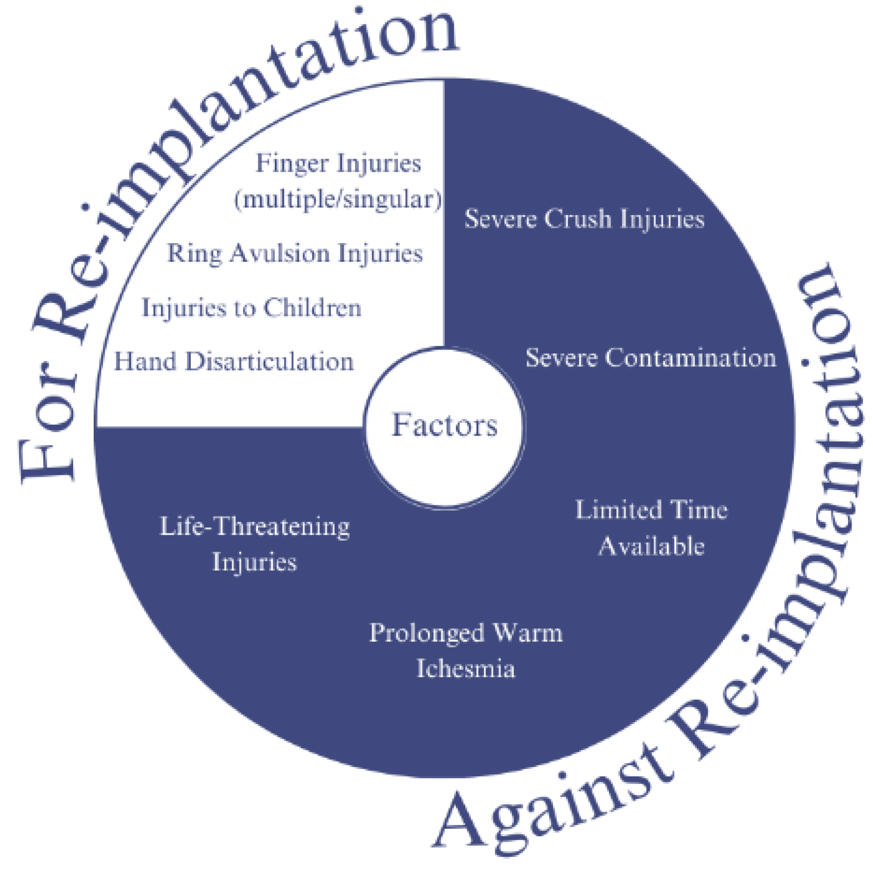
Traumatic amputation is an immediate disarticulation of body parts resulting from an accident or injury. Replantation is a surgical procedure to reattach or replant already disarticulated limbs or body parts. There are some factors that need to be taken into consideration to choose between replantation and amputation, this consideration and factors are listed in
Figure 11 [
102,
103,
104,
105,
106].
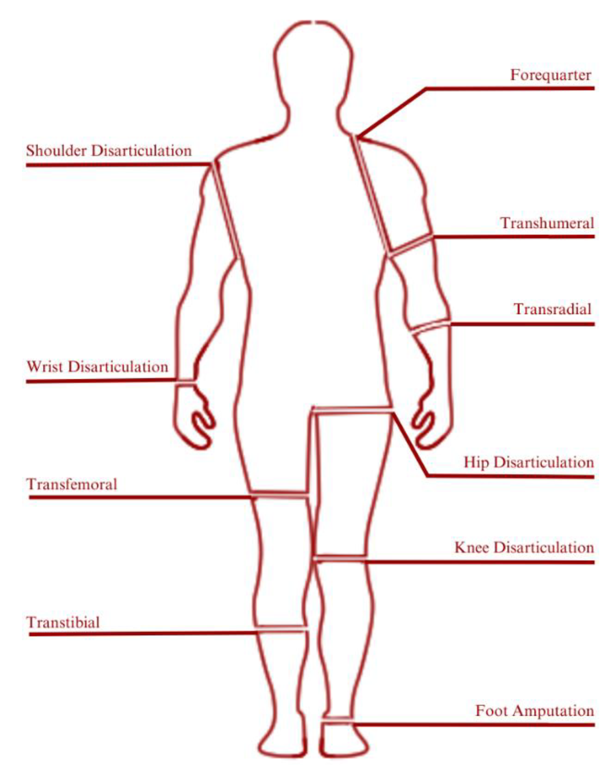
Amputation level is closely related to the classification of prosthetic devices. Generally, prosthetic devices are classified into two main categories that are lower-extremity and upper-extremity prosthetics.
Figure 12 illustrates the classification of prosthetic devices based on the level of amputation [
107].
The ratio of lower limb amputation compared with upper limb amputation could reach a ratio of 11:1 [
108]. A transtibial prosthetic is divided into an interface, suspension, shank, joint, and foot part. To better visualize the composition of transtibial prosthetics, refer to
Figure 13 [
99].
An interface is a part of the prosthetic having the role of connecting the residual limb to the prosthetic. An interface must be able to provide fitting, cushion, and shock absorption. The interface part is divided based on the material into hard material (like wood), and soft material (like closed-cell foam). Materials like wood are used early on thanks to its simple manufacturing methods and abundant, easy-to-find materials needed. In terms of maintenance, this type of interface material is relatively easy to maintain thanks to its high durability. Despite its ease of production, this type of interface material comes with inherent disadvantages, mainly its lack of cushioning. This disadvantage is the reason later soft material interface was put into consideration. Common materials used for soft interface materials are made of closed-cell foam. This material is used because of its waterproof properties, accompanied by its malleability makes it a material that is easy to mold based on user characteristics [
109]. Suspension refers to the part which holds the prosthetic in place when worn. A good suspension should be able to provide zero relative movements against the residual limb. A badly fitted suspension would cause a condition known as “pistoning”. Pistoning is and could cause pain, skin breakdown, irritation, and non-responsive prosthetic movement. Waist belt, joint and corset, and sleeve.
The choice of what is the best type of suspension and interface parts for a transtibial prosthetic is different from person to person. Essentially, other than to replace a missing ambulatory capability, a prosthetic is also aimed at the comfort of its user. This means that the best choice lies in what makes the user most comfortable. Whichever type of interface is chosen, there has to be an accurate impression technique to support it. Such impression techniques consist of hand casting, pressure casting, and optical scanning. Apart from the impression, another aspect of fitting a prosthetic involves the act of alignment. The bench alignment method is one of the most common methods of alignment, though there exists a more advanced and accurate alignment technology known as electronic alignment. This method requires the use of sensors fitted into the prosthetic to provide data in terms of user gait behavior when wearing the prosthetic. This method is capable of providing data that is unavailable from bench alignment such as socket load over a period of time walking.
6. Future Prospect
To better validate our claim, we will also provide some examples of early development into the implementation individually. Overall the future prospect is divided into potential use in a protective application, robotic application, and aerospace application. The potential for protective device application results from the unique way it deforms. Past research has shown that an auxetic sandwich panel experienced a local internal contraction in response to impact force from impact [
63]. This will support the sandwich panel to resist damage and absorb more energy from the impact. Studies have shown that compared to conventional sandwich panels and homogenous materials, an auxetic sandwich panel has proven to have an effective potential in this field.
In terms of robotic applications, auxetic material offers the capability to form and shape matching and, depending on the material used, is likely to have higher flexibility. Shape matching has been proven viable in non-robotic studies [
83]. Soft auxetic metamaterial has been further explored to be implemented in a soft robotic gripper [
110]. Implementing auxetic metamaterials in an inchworm-type soft robotic will ease it to crawl through narrow channels. This is attainable through the high flexibility an auxetic metamaterial provides. The most enticing advantage of auxetic metamaterials in aerospace application is its lightweight property. As mentioned earlier in this article, metamaterials mainly consist of lattice or highly porous structures filled with voids. This leads to lighter materials compared to conventional ones with the same overall dimension. Research exploring the idea of auxetic in aerospace, including the application in a satellite antenna [
111]. Another study has also proven the possibility of combining different materials on the same auxetic metamaterials forming what is known as multi-material auxetic metamaterials [
112]. It opens up nearly infinite possibilities to customize an auxetic metamaterial based on specific needs and requirements. Instances of research investigating the performance of multi-material auxetic are by combining soft properties of FlexPro elastomers and Polyurethane Shape Memory Polymer for its smart properties [
88].
Throughout its history, the development of auxetic geometries has been explored thoroughly. But novel geometries have been found nearly every year since the first concept of auxetic metamaterials started. From the earlier geometries like the re-entrant hexagon studied by L.J Gibson in 1997 to the more recent geometry like the hourglass lattice proposed in 2021 [
113]. This trend shows that even the generation of newer geometry still has a high potential to be further explored, ranging for more varied base geometries. Lastly, to summarize the content of this section,
Figure 14 illustrates the potential and future prospects of auxetic metamaterials that have been discussed above.
Figure 2.
The use of auxetic materials in prosthetics is still in the early stages of development; there is promising research being done in this area. As the technology and understanding of auxetic materials continue to evolve, we may see more widespread use of these materials in prosthetic design and development in the future. One of the developments implemented on materials is metamaterials. Some research has been conducted on metamaterials to change and enhance the properties of its prosthetics.
Figure 3.
Implementation of auxetic metamaterials for interface part of a transtibial prosthetic. (A). Unit cell of four triangles orthogonally arranged. (B). The variation was made on the draft angle of the wall. (C). The layout of inlay in regards to inlay and residual limb in exploded view. (D). The results of Yeoh 3rd order representation show good agreement for a higher draft angle when compared with experimental data taken from experimental testing of the material sample. For the lower draft angle, the model shows a slight error caused by the inherent limitation for Yeoh 3rd order representation in representing a drastic change in buckling, such is the condition that exists for the lower draft angle. (E). Visual representation for the FEA results to analyze PS and PPG. This resulting gradient reduction capability is compared to the “No Inlay” condition.
Figure 6.
The use of auxetic materials in prosthetics for the toe part of the foot. (A). The overall dimension of the prosthetic foot, with the indicated area denoting the location for implementing the auxetic structure. (B). The design parameter used for the re-entrant hexagon used in this study. (C–E). shows the modeled foot variance from Type 1, 1S, 2, 2S, and 3 (left side of each figure), while the right side shows the results of toe torque over the toe angle from the FEM. (F). Visualize the end process of the optimization method using NSGA-II to gain the optimal design. For validation, this optimized design was then compared to the human gait data. From the graph shown (G), it is concluded that the optimized design shows good agreement in mimicking the behavior of the natural human toe behavior.
Figure 7.
The use of auxetic materials in prosthetics for an orthopedic bone plate. (A1,B1) illustrated the design parameter considered for each type of structure (re-entrant hexagon and missing rib, respectively). (A2,B2) show the 3D modeled CAD made using SolidWorks. While (A3,A4) show the results for preliminary FEA to evaluate the behavior of the unit cell when in tensile of 20% strain ((A3) for IA = 50 degree, and (A4) for IA = 90 degree). (C1). Shows the CAD model for the bone plate specimen with the positioning of the auxetic structure in the middle. (C2). Visualize the results of finite element analysis in terms of stress contours and displacement contours for (C3). An equivalent experimental test was done based on ASTM F-32 on the 3D printed stainless steel specimens using INSTRON machine (D1). (D2–D4) are the photographs for the specimen after the experimental test for the control specimen, re-entrant hexagon, and missing rib structure, respectively.
Figure 8.
Development and improvement of Re-entrant Structure: Re-entrant structures have potential applications in various fields, including aerospace, biomedical engineering, and energy storage. They offer a promising avenue for creating lightweight, high-strength materials with unique mechanical properties. As research in this area continues to progress, we may see even more significant advancements and innovations in the design and development of re-entrant structures. Re-entrant structures are materials or structures that have repeated branching and folding patterns at different scales. They can be found in many natural materials, such as collagen fibers, bones, and plant tissues. Recently, re-entrant structures have gained significant attention in materials science and engineering due to their unique mechanical properties, including high stiffness, strength, and toughness.
Figure 9.
Development and improvement of Chiral Structure: Chiral structures also have potential applications in various fields, including optics, sensing, and energy storage. They offer a promising avenue for creating materials with unique properties that can be tailored for specific applications. As research in this area continues to progress, we may see even more significant advancements and innovations in the design and development of chiral structures. Chiral structures are structures that have mirror-image symmetry, meaning that they cannot be superimposed on their own reflection. They can be found in various natural materials, such as spider silk and collagen fibers. Chiral structures have gained significant attention in recent years due to their unique mechanical, optical, and biological properties.
Figure 10.
Subclasses of Rotation-based Polygon: Rotation-based polygons are a type of self-intersecting polygon that are formed by repeatedly rotating a line segment around a fixed point. These polygons can be classified into several subclasses based on their geometric properties. One subclass of rotation-based polygons is the monotone subclass, which is a polygon that can be divided into two monotone chains such that each chain is non-intersecting and has the property that any horizontal line intersects the chain at most twice. Monotone polygons have useful properties that make them well-suited for certain algorithms, such as triangulation algorithms. Another subclass of rotation-based polygons is the star subclass, which is a polygon that has a single vertex from which all other vertices are visible. Star polygons can be further classified into convex and non-convex subclasses. Convex star polygons are those in which all internal angles are less than 180 degrees, while non-convex star polygons have at least one internal angle greater than 180 degrees.
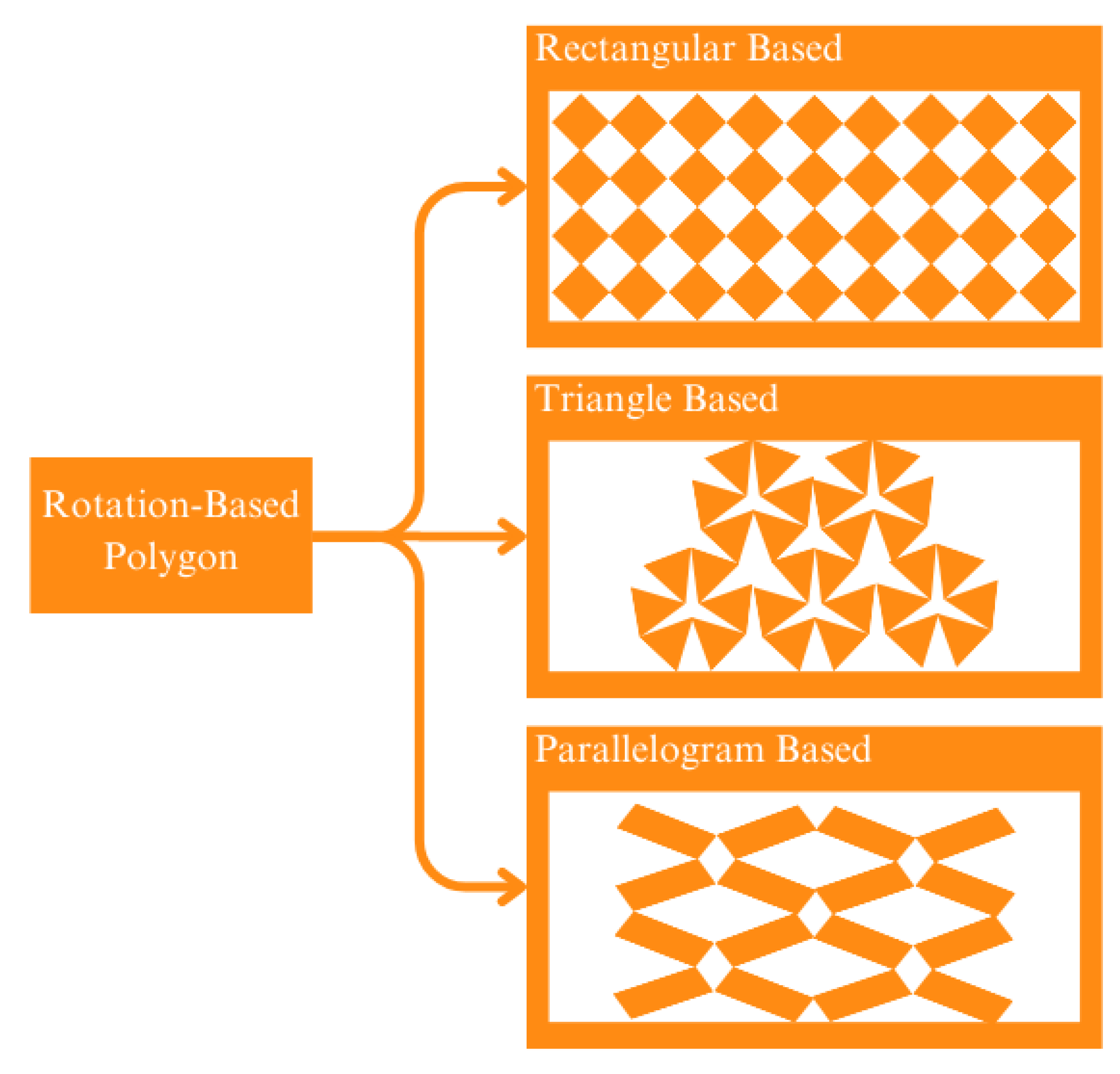
Figure 11.
Consideration of Replantation for Post-Traumatic Disarticulation: Replantation is a surgical procedure that involves reattaching a body part, such as a finger or limb, that has been completely severed from the body. Post-traumatic disarticulation refers to the loss of a limb or body part as a result of a traumatic injury. In cases where replantation is not possible or not recommended, other treatment options, such as prosthetics or physical therapy, may be considered to help patients regain function and improve their quality of life. Ultimately, the decision to pursue replantation must be made on a case-by-case basis, with careful consideration of the patient’s individual circumstances and needs.
Figure 12.
Prosthetic Classification Based on Amputation/Disarticulaltion Levels: Prosthetics are artificial devices that replace missing body parts or limbs. Prosthetic limbs are designed to compensate for the loss of a limb, and the type of prosthetic required often depends on the level of amputation or disarticulation. The level of amputation or disarticulation determines the type of prosthetic limb that is required, and the prosthetic must be carefully fitted and adjusted to the individual’s needs to ensure the best possible function and comfort. Of the existing prosthetic classifications, transtibial is the discussion that we review. The transtibial prosthetic has several parts. Of the several existing parts, metamaterials are used as the development of prosthetic technology. Some of them are parts of the sole, socket, foot and suspension parts.
Figure 13.
Composition of Transtibial Prosthetic: It is possible to develop the components of a transtibial prosthetic using auxetic metamaterials, but it would depend on the specific application and requirements of the prosthetic. Auxetic materials are unique in that they have a negative Poisson’s ratio, meaning that they expand in all directions when stretched. This property can be advantageous for certain applications, such as providing better shock absorption or improving energy return. For example, auxetic materials have been studied for use in prosthetic sockets to provide improved comfort and stability for amputees. The unique expansion properties of the auxetic material can help distribute pressure more evenly over the residual limb, reducing discomfort and the risk of injury. However, it is important to note that the design and development of prosthetic components using auxetic metamaterials is still a relatively new area of research, and there are many factors to consider when selecting materials and designing components for prosthetics. These include factors such as strength, durability, weight, and cost, among others.
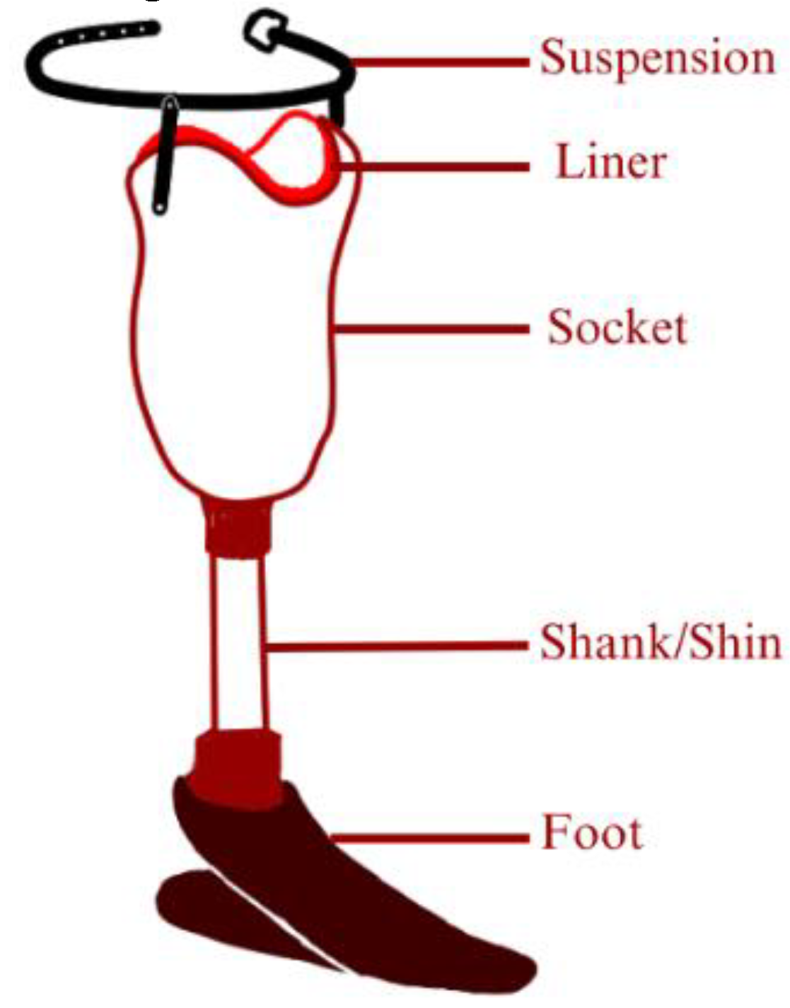
Figure 14.
Potential and Future Prospects of Auxetic Metamaterials: Auxetic metamaterials have the potential to revolutionize the design and function of prosthetic transtibial components in several ways. Here are some potential and future prospects of auxetic metamaterials for prosthetic transtibial. Improved comfort: Auxetic materials have been shown to have unique mechanical properties that can provide improved comfort for amputees. For example, auxetic materials can distribute pressure more evenly over the residual limb, reducing discomfort and the risk of injury. Better shock absorption: The expansion properties of auxetic materials can help absorb shocks and vibrations, which can be beneficial for amputees who engage in physical activities such as running or jumping. Customizable designs: Auxetic metamaterials can be engineered to have specific properties and shapes, making them highly customizable for individual needs. This can result in more personalized and effective prosthetic transtibial components. Reduced weight: Many auxetic materials are lightweight and can be used to reduce the weight of prosthetic transtibial components, which can improve mobility and reduce fatigue. Durability: Some auxetic materials have been shown to have improved durability compared to traditional materials, which can lead to longer-lasting prosthetic components. Energy return: Some auxetic materials can store and release energy, which can be beneficial for amputees who require more energy-efficient prosthetic transtibial components. Overall, the future prospects of auxetic metamaterials for prosthetic transtibial are promising. However, further research and development are needed to optimize the design and properties of these materials for specific applications in prosthetics. Additionally, cost-effectiveness and availability are important considerations when developing new materials and technologies for prosthetics.
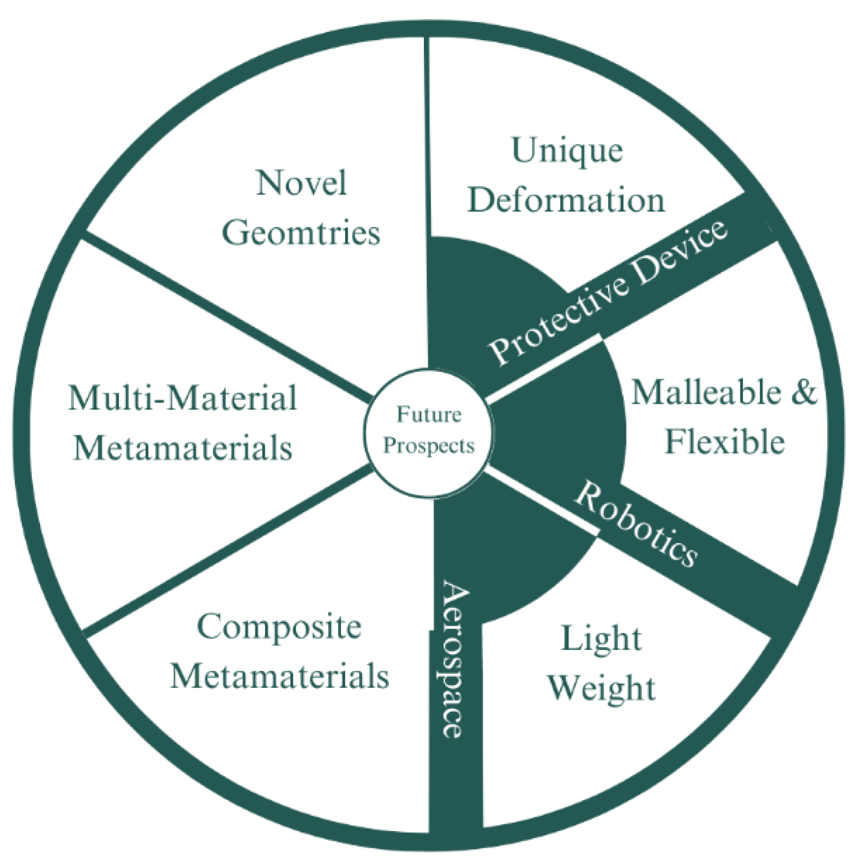
Table 1.
Poisson’s Ratio of Common Materials.
Table 1.
Poisson’s Ratio of Common Materials.
| Materials |
Poisson’s Ratio |
| Stainless Steel [42] |
0.2535–0.2774 |
| Thermoplastic Polyurethane Foam [43] |
0.25 |
| Nanoporous Gold [44] |
0.4 |
| Carbon Fibre [45] |
0.26–0.28 |
| Cork [46,47] |
0 |
| Cat Skin [48,49] |
-0.3 |
Table 2.
Methodological Comparison of Past Studies.
Table 2.
Methodological Comparison of Past Studies.
| Name/Title |
Objective |
Comparison Aspect |
| FEA Tool |
FEA Method |
Material |
Validation |
| General Comparison [79] |
Comparing mechanical properties of past Auxetic Geometries |
NX-Nastran |
Compression |
Epoxy Resin |
Past Data |
| 3D Re-entrant Hexagon [80] |
Developing analytical model |
Solidworks COSMOS |
Compression |
VeroWhitePlus |
Experimental |
| Ancient Motif [81] |
Developing structure based on existing (ancient) geometries |
N/A |
Tensile |
Natural Latex Rubber |
Experimental |
| Blast Resistance (Re-entrant Hexagon) [18] |
Investigating blast resistance of an auxetic panel |
LS-DYNA |
Blast Test |
Aluminium Alloy |
Experimental |
| Graded auxetic hexagon [82] |
Investigating flexural properties of auxetic panel |
ABAQUS |
3-P-Flexural |
PLA |
ExperimentalDIC |
| Planar 3D Chiral with rectangular central node [73] |
Investigating mechanical properties of novel arrangement for 3D Chiral |
ANSYS APDL |
Compression |
UV Curable Resin |
Experimental |
| Shape matching [83] |
Developing the concept of shape-matching |
ABAQUS |
Tensile |
PLA |
Experimental |
| Non-Positive Thermal Expansion [84] |
Developing 3D structure with two unique behavior |
ANSYS |
Compression |
Steel-Invar & Aluminium-Invar |
Numerical |
| Star Honeycomb [85] |
Investigating crushing behavior on star honeycomb |
LS-DYNA |
Crushing |
Aluminium Alloy |
Numerical |
| Peanut Inspired [86] |
Developing 2D structure based on natural geometries |
ABAQUS |
Tensile |
PLA |
Experimental |
| Turtle Inspired [87] |
Developing 2D structure based on natural geometries |
ABAQUS |
Compression |
Aluminium |
Numerical |
| 4D Printing SMP [88] |
Developing Shape-Memory-Alloy |
ANSYS |
Tensile |
SMPFlexPro |
Experimental |
| Foam for Structure [58] |
Investigating the effect of filler foam in hexagonal structure |
ABAQUS |
Compression |
TPUSR & FR Foam |
Experimental |
| Ballistic Resistance [89] |
Investigating the potential of auxetic for ballistic resistance |
ABAQUS |
Ballistic Impact |
Carbon FiberEpoxy Resin |
Experimental |
| Foam for Tubular Auxetic [59] |
Investigating the effect of filler foam in tubular auxetic structure |
ABAQUS |
Compression |
Stainless SteelPU Foam |
Experimental |
| Additional Node for re-entrant hexagon [64] |
Modifying the design of re-entrant hexagon by applying additional nodes |
ABAQUS |
Compression |
ABS |
Experimental |
| Stretching dominated deformation [90] |
Developing a structure with deformation behavior that is dominated by stretching |
ABAQUS |
Compression |
CFRP |
Experimental |
| Double U [14] |
Improving mechanical properties by converting into curve (Double U) |
ABAQUS |
Compression |
Stainless Steel |
Experimental |
| Additional Ligament DAH and re-entrant hexagon [66] |
Improving stiffness by adding ligament |
ABAQUS |
Tensile |
SLA |
Experimental |
| 3D Planar anti-chiral [91] |
Implementation of oblique node on auxetic structure |
ABAQUS |
Tensile |
VeroWhitePlus |
Experimental |
| Graded chiral [92] |
Investigating the out-of-plane impact energy absorption of graded chiral |
ABAQUS |
Dynamic Crushing |
DP590 Steel |
Numerical |
| Auxetic stent [19] |
Designing auxetic stent for CAD |
ABAQUS |
Practical Simulation |
316L Stainless Steel |
Theoretical |
| Ballistic resistance honeycomb sandwich [93] |
Examining the performance of HSP with auxetic structure |
ANSYS & LS DYNA |
Ballistic impact simulation |
Aluminium alloy AA6060 T4 |
Theoretical |
| Inverted tetrapod [94] |
Proposing the base geometry of inverted tetrapod as auxetic structure |
LS-DYNA |
Quasi-static |
Ti-6A1-4V Alloy powder |
Experimental |
| Out-of-plane ballistic performance [95] |
Exploring the performance of out-of-plane ballistic performance of different HSP |
ABAQUS |
Ballistic impact simulation |
5052-H39 Aluminium sheets |
Numerical |
| RPC filler for honeycomb [96] |
Examining the performance of auxetic HSP filled with RPC |
LS-DYNA |
Ballistic impact simulation |
45 Steel |
Numerical |
| Sandwich panel with CFRP sheet [97] |
Applying a CFRP as face sheet for auxetic HSP |
LS-DYNA |
Ballistic impact |
AlSi10Mg |
Experimental |
| Auxetic in doubly curved HSP [98] |
Implementation of oblique node on auxetic structure |
ABAQUS |
Tensile |
VeroWhitePlus |
Experimental |
| Modified Re-entrant Honeycomb [16] |
Additional horizontal member between vertical and re-entrant on a semi-re-entrant honeycomb model |
Soliworks & ABAQUS |
Tensile |
Acrylic Sheet |
Experimental& Numerical |
Table 3.
Limitations and Comparison for State-of-the-arts Prosthetic.
Table 3.
Limitations and Comparison for State-of-the-arts Prosthetic.
| Comparison |
State-of-the-arts |
| Transtibial Socket Inlay |
Transfemoral Socket Liner |
Heel-Off Foot |
Toe-Off Foot |
Bone Implant |
| Testing Method |
Both |
FEA |
FEA |
FEA |
Both |
| Sample Material Fabrication |
Yes |
No |
No |
No |
Yes |
| Prototyping |
No |
No |
No |
No |
Yes |
| Sample Experimental Testing |
ASTM D575 |
No |
No |
No |
ASTM F-32 |
| Prototype Practical Testing |
No |
No |
No |
No |
No |
| Validation |
Experimental |
Numerical |
Numerical |
Gait Data |
Experimental |
