1. Introduction
The fiber optic industry had a significant development from the late 80's. Besides communication, this technology is also being used for measuring a monitoring deformation, displacement, acceleration, pressure, temperature, and chemical properties among others [
1]. Distributed fiber optic monitoring systems have become significantly popular in geotechnical applications as they can provide distributed strain and temperature measurements with high accuracy along any monitored area without any gaps.
The first optical communication systems date back to 1790, when the French Claude Chappe1 invented the optical telegraph, although it was only in 1870 that the English physicist John Tyndall demonstrated the principle of light conduction through a simple experiment with a flashlight inside an opaque container filled with holes and water, he proved that light could bend [
2]. In 1880, Alexander Graham Bell developed an optical voice transmission system, the Fotofen, using light free space to transport the human voice up to 200 meters away. The system converted voice signals into optical signals, using sunlight and lenses mounted on a receiver that vibrated as a result of sound waves [
2]. Much later, in 1952, physicist Narinder Singh Kapany studied the singularities of total internal reflection looking for a material that had the lowest refractive index so that light could travel a curved path inside a material [
2]. His experiments led him to the invention of fiber optics, used at the time in the field of medicine.
Afterwards, the Chinese physicist Charles Kao had the idea of using optical fibers to transmit telephone calls [
2]. The discovery of fiber optics revolutionized the telecommunications area. A small glass fiber became capable of transmitting more information and with greater speed than all existing electrical technologies to date. The scientific community and industry quickly became aware of the potential of this technology. Efforts were joined in the production of optical fibers with better performance and new light sources and new photodetectors were developed that quickly contributed to the proliferation of optical fibers in the communications industry.
Despite the first optical fiber use being particularly related to data transmission, its potential as a sensor element was soon discovered [
3], presenting what can be considered the first fiber optic sensor. They measure variations in the path taken by light inside a fiber and thus managed to quantify its deformation. Since then, multiple technologies related to optical fiber sensors, based on the exploration of different properties of fibers and light, have been discovered and explored.
The first fiber optic sensors, which are considered the beginning of instrumentation, were the gyroscopes, showing through experiments that the range of physical quantities that could be measured with fiber optic sensors was vast. In the early days, several types of applications were foreseen for this technology, namely in the field of industrial sensors. However, the high cost of sensors at the time restricted applications to a small number of industries which corresponded to the most important areas of monitoring, such as instrumentation in medicine, defense systems and aeronautics. Subsequently, applications extended to environmental monitoring and, more recently, to civil engineering. Applications to telecommunications systems are due to major advances in the development of fibers and optical sensors.
Currently, with the expansion of the communications network worldwide, there is a greater availability of optical and electronic components that associate high quality with reasonable costs [
4]. In recent years, the electronics industry has made available highly sensitive equipment capable of detecting small variations in the physical properties of optical fiber when subjected to small changes, making it possible to measure different magnitudes [
4,
5,
6,
7], such as already commented. On the other hand, fiber optic sensors are an increasingly valid option for structures whose monitoring must be carried out in real time, sometimes involving great distances.
Structural instrumentation was dominated for many years by sensors of an electrical nature. For information purposes, the importance of electrical resistance strain gauges, vibrating cord strain gauges, strain gauge load cells, LVDT, PT100, etc., used in the measurement of the most diverse structural magnitudes, is highlighted [
8,
9].
Technological evolution has pointed to increasingly reliable, robust, and economical solutions. Geotechnical instrumentation emerged and began to be applied between the 1930s and 1940s [
10]. The author reports that in the first 50 years following the emergence of instrumentation, there were major changes in this field. The predominance of the use of simple, mechanical, and hydraulic instruments gave way to safer and more complex instruments with electrical and pneumatic transducers. In 1988, Dunnicliff already warned of the advent of automatic data acquisition systems and computerized data processing.
Geotechnical instrumentation is responsible for providing data that help decision-making at any stage of the project, in order to reduce or avoid catastrophic situations. Soils and rocks have anisotropic and heterogeneous characteristics that, added to the complexity of local hydrological conditions, lead to a series of uncertainties regarding soil deformation [
11]. This fact is one of the great challenges of geotechnical engineering, regarding monitoring the deformation of these materials at the surface and subsurface level. Regarding these factors, several conventional monitoring technologies are used, but these only allow the knowledge of the measures taken occasionally, with a limited amount of data. With the aid of fiber optic technology, different monitoring methods can be proposed that even allow establishing a soil displacement profile with greater precision and safety.
The application of fiber optic sensors for geotechnical monitoring has been used worldwide. The use of a fiber optic cable can cover the monitoring of a much larger area when compared to conventional instrumentation. Works by [
12,
13,
14,
15,
16] are some examples that prove the technology's potential.
Over the last three decades, several technologies and optical properties have been approached for the evaluation of different magnitudes using the measurement of variations in the properties of light transported in optical fibers, such as its intensity, frequency, wavelength, phase, or polarity [
17] and [
18].
From a metrological point of view, its high stability, precision, and resolution stand out. From the point of view of durability, the fact that they are made of a non-corrosive and chemically stable material stands out. For applications in the field of geotechnical engineering, it is relevant that they have total immunity to electromagnetic interference, which in practice results in the total absence of electrical noise, as well as the fact that they allow signal transmission over long distances. without any degradation or interference.
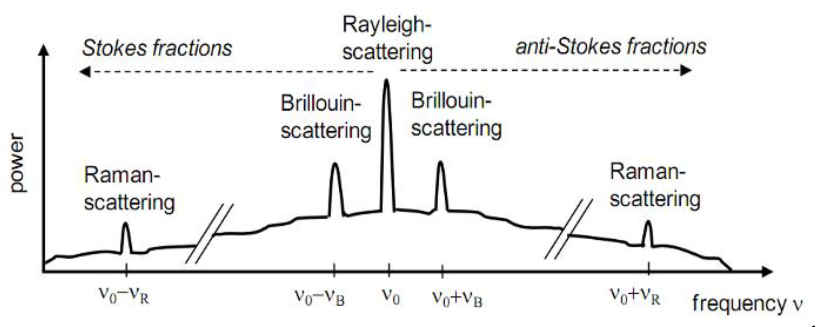
Punctual or local optical sensors allow the measurement of physical quantities at discrete place or points. They correspond to sensors with a measurement base of a few millimeters. In the case of structural monitoring, they are particularly suitable for assessing local effects, being able to capture the concentration of effects with high accuracy. As an example of punctual sensors, it can be mentioned the Bragg sensors and the Fabry-Perot interferometers. The case of distributed optical sensors is a unique aspect of fiber optic sensors. This configuration allows the evaluation of a given physical quantity along the entire length of the sensor in a continuous way in space. Variation profiles can be achieved over developments that can reach several kilometers. They are particularly suitable sensors for detecting and locating damage in highly developed structural elements such as foundations, dams, pipelines, and geotechnical works in general. The technology of Brillouin and Raman sensors has boosted the creation of distributed fiber optic sensors.
Among the technological advantages of the use of fiber optic sensors, the most notable are: (i) sensing the possibility of several signals over a single optical fiber (multiplexing data), (ii) ease of reading of the signals (good value signal versus noise), (iii) measurements over long distances (remote sensing), (iv) immunity to electromagnetic fields, (v) absence of spark, and (vi) low weight and low material reactivity.
The use of fiber optics as a tool for different kinds of geotechnical monitoring can become highly attractive and cost effective when compared to conventional instruments such as piezometers, inclinometers, among others. A single fiber optic cable may cover a larger monitoring area compared to conventional instrumentation, and the possibility of monitoring more than one physical quantity with the same fiber optic cable.
Consulting the literature, it is possible to find several different examples where distributed fiber optic systems are being used for monitoring slopes [
19,
20], tunnels [
21,
22], mass movements [
23], slope monitoring [
24], geotechnical structural elements [
25] such as pile foundations [
26,
27,
28,
29,
30,
31] and landfills [
32], in addition to those mentioned above. For this, the interrogator, the optical sensor cable, and the installation technique must be properly adjusted to guarantee the quality of the measurement results.
Analogously to conventional sensors, a sensor calibration curve is required to derive strain values from the frequency measurement quantity. However, fiber optic sensor cable manufacturers often do not provide their own calibration parameters being necessary consult the values in the specialized literature, which can result in monitoring errors [
33].
The Institute of Engineering Geodesy and Measurement Systems, IGMS developed a unique calibration facility [
34], which enables highly precise, fully automatic calibration of strain sensors with lengths of up to 30 m under stable laboratory conditions. Prior to field measurements, individual calibrations of several samples of the used sensing cables are usually carried out to reliably determine the frequency-to-strain relation. Results of various calibrations of different sensing cables for geotechnical applications from Solifos AG (e.g., types V3 and V9) are shown for [
35].
Over the 2021, it was developed a calibration facility using calibration bench that enables highly precise, fully automatic calibration of strain sensors with lengths of up to 30 m under stable laboratory conditions. Prior to field applications and measurements, calibrations of a Brazilian and an UK fiber optical sensors cable were carried out to determine the frequency and temperature to strain relation.
This article covers all steps undertaken to define function of strain variations of two different single mode optical fiber cables, using two different distributed interrogators. To fulfill this objective, this paper shows calibrations were carried out in Lactec (city of Curitiba, Parana State, Brazil), results and conclusions. [
34] presented a work focused on the calibration results of the fiber optic-based monitoring system, however, the article in question does not observe detailed details of the methods used in the calibration tests of strain and temperature performed, aiming at possible reproduction. Therefore, this article proposes a methodology for calibrating the deformation of fiber optic cables, since the calibration parameters are provided by the cable manufacturers, which can result in errors depending on the application.
It should be noted that there are few manufacturers of fiber optic cables aimed at application in civil engineering. Therefore, with the calibration methodology proposed in this article, it is intended to transmit to the academic community the possibility of obtaining calibration parameters of any fiber optic cable, even those manufactured for telecommunications purposes and not only for cables manufactured with the intended use in civil engineering. Given this, researchers will not be restricted to the acquisition of special cables for their applications.
3. Material and methods
For cable of fiber optical calibration, the materials and methods used are presented below.
3.1. Optical cables and interrogators unit
The DTSS and the DSTS interrogators used in calibrations tests are a monitoring system developed by Sensornet and OZ Optics, which measures the Brillouin spectrum, with a resolution of 1.02 m along the fiber and with the analysis of the data obtained, it is possible to obtain strain data and temperature at all points along the cable [
37].
In the DSTS interrogator from the manufacturer OZ Optics, the difference in resolution occurs between the BOTDA system (Brillouin Optical Time Domain Analysis) since the difference in resolutions in the DTSS interrogator occurs between the BOTDR system (Optical Time Domain Reflectometer).
The methods also differ in terms of how the optical fiber is connected to the interrogator. The first has a spatial resolution of less than 1 m, 0.1°C for temperature measurements and 2 με for strain measurements, in which the optical fiber is connected at both ends causing the reading to be done in the loop way, starting at one end, and ending at the other. In the BOTDR, the fiber is connected only at one end, it has a spatial resolution of 1 m, 0.8°C for temperature measurements and 16 με for strain measurements, according to the manufacturer's catalog.
The objective of using two interrogators simultaneously in the calibration methodology presented here was to seek knowledge about obtaining the same calibration parameters regardless of the interrogator used. In addition, it is known that with the BOTDA method, data with better spatial resolution can be obtained in relation to the BOTDR.
Table 1 presents a summary of the characteristics of the cited interrogators.
There is also a difference between the manufacture of optical cables, the loose tube type cables are those in which the fibers are placed loosely inside the tubes that make up the structure of the cable, as the fibers are not attached to the cable, the mechanical interferences that happen externally are not totally felt by them. These types of cables are more suitable for temperature readings since deformations in the cable are not transmitted directly to the optical fibers. For tight buffer type cables, the fibers are attached through a secondary coating and as the fibers are joined to the cable all external interference is transmitted to the fibers, so tight buffer cables are more suitable for strain measurements. Typically, tight buffer cables are constructed with kevlar fibers to join the optical fibers to the cable.
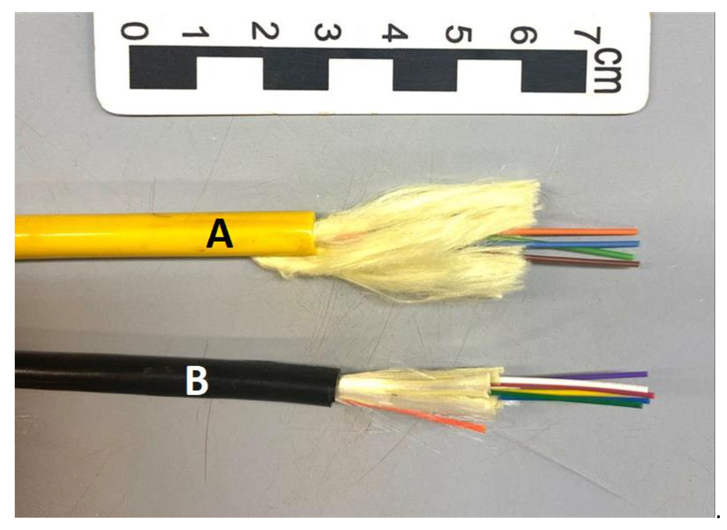
The first optical cable used in the tests to determine the cable calibration parameter for strain measurements is sold by Sensornet (
Figure 2A). This fiber optic cable has 6.5 mm in diameter and it is made up of 4 optical fibers, two of which are multimode (green and brown) and two are single-mode (blue and orange). It has tensile reinforcement elements such as kevlar fibers surrounded by an external protection layer, as can be seen in
Figure 2. The maximum tensile strength of this fiber optic cable, informed by the contractor, is 3 kN and maximum deformation of 20,000 µε (equivalent to 2%).
The second optical cable used in the tests to determine the cable calibration parameter for strain measurements is sold by the manufacturer Furukawa. Fiber optic cable is made up of tight buffer single-mode optical fibers. The optical fibers have a primary coating in acrylate and a secondary coating in thermoplastic material. On the set of fibers, tensile elements of dielectric wires are placed. The set of fibers is protected against water penetration and has an outer layer in thermoplastic material that does not propagate flame and is weather resistant. It has a nominal external diameter of 5.6 mm and consists of 6 optical fibers. The maximum tensile strength of this fiber optic cable, informed by the contracting party, is 1.85 kN. In
Figure 2B there is an illustration of the cable.
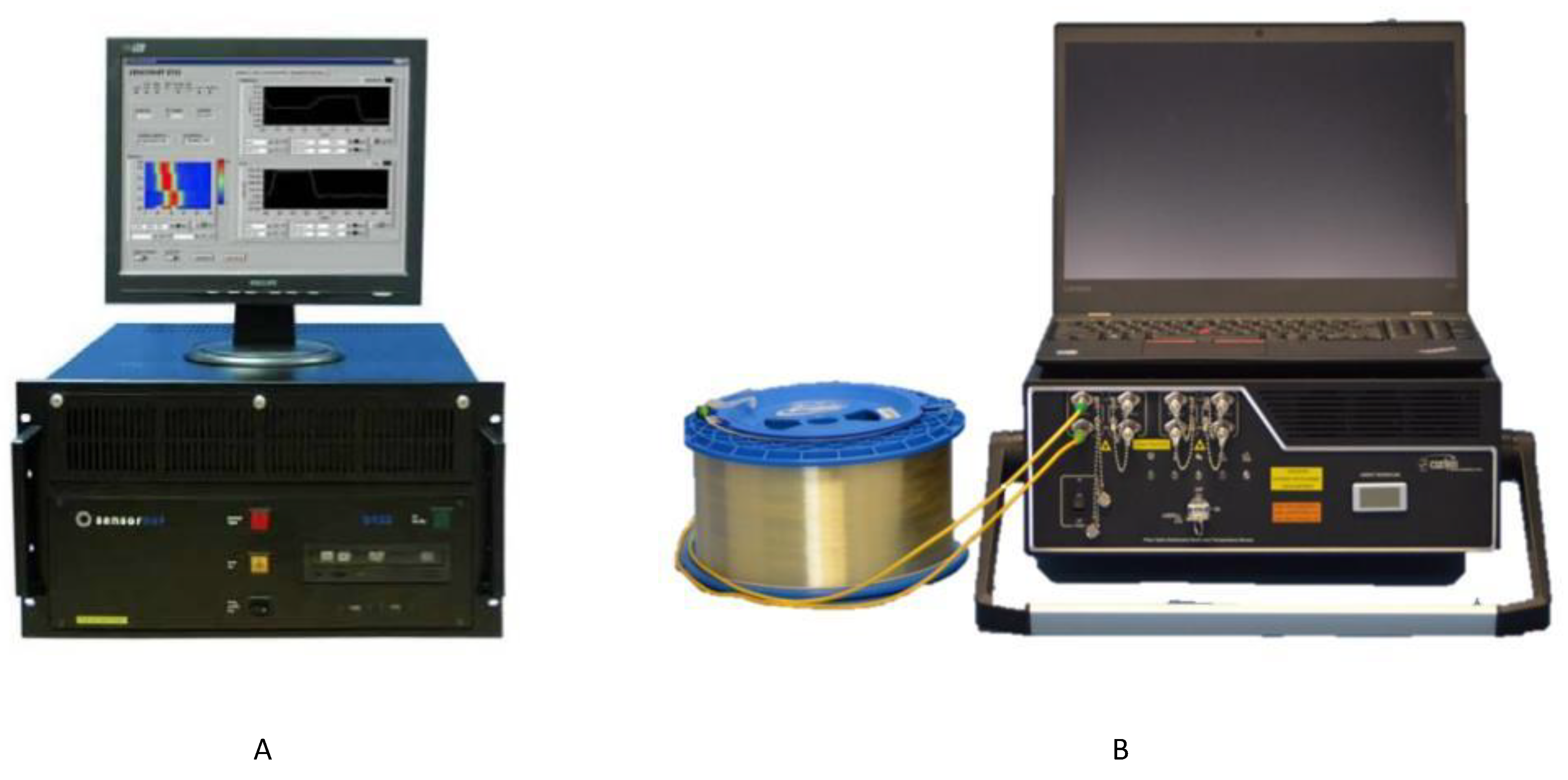
In the optical cable calibration tests, two optical fiber distributed interrogators were used. A DTSS interrogator manufactured by Sensornet and a DSTS interrogator manufactured by Oz Optics. The two interrogators record Brillouin frequencies for later calculations to convert the frequency into temperature and/or strain. In other words, the DTSS interrogator has BOTDR technology that uses Brillouin spontaneous backscattering. This backscatter allows measuring deformations and/or temperature at any point along the optical fiber, with a spatial resolution of 1.02 meters. In BOTDR technology, a single laser beam is pulsed at one end of the fiber. A small percentage of this backscattered light returns to the emitting source by spontaneous backscattering of the Brillouin Spectrum. Spectrum Brillouin frequency analysis is a consequence of changes in strain and/or temperature, while the travel time of the backscattered light pulse determines the measurement position along the length of the fiber.
Figure 3A shows Sensornet DTSS interrogator.
The DSTS interrogator has both technologies in its system, BOTDR and BOTDA. BOTDA technology utilizes Brillouin Stimulated Backscatter. The main difference is that two laser beams are injected on opposite sides at the ends of the fiber. A continuous wave beam is injected at one end while a laser pulse is injected at the other end of the fiber. In BOTDA, energy transfer occurs from one beam to the other, but the loss in the continuous wave beam is what is used for data interpretation. Although BOTDA technology requires access to both ends of the fiber, it has some advantages, such as spatial resolution of up to 0.04 meters; reading intervals with shorter acquisition time; and possibility of monitoring up to 100 km of fiber.
Figure 3B shows a photograph of OZ Optics DSTS interrogator. As already mentioned, to use optical fiber or fiber optic cables in experiments and subsequent use in experimental field, it is necessary to determine parameters of calibrated strain measurements.
3.2. Conventional sensors
For displacement measurements, two inductive linear displacement transducers (LVDT – Linear Variable Differential Transformer) were used, one WA200 (with a measurement capacity of 200 mm) and another one WA300 (with a measurement capacity of 300 mm), both supplied by HBM. The maximum linearity deviation is 0.2% in relation to the sensitivity, which is 80 mV/V (
Figure 4A).
Tensile force readings on the sample were taken by an HBM load cell (Hottinger Baldwin Messtechnik) S9M, with a capacity of 5 kN, nominal sensitivity of 2 mV/V and accuracy class 0.02, which provides the values to the control systems. (
Figure 4B).
The test temperature control was carried out by three air conditioners with frequency inverter and is done by the average of the temperature read by seven T-type thermocouples (
Figure 5C) installed along the sample, at approximately 1650 mm from each other. For tests at temperatures above 26 °C, a heating system consisting of fourteen electrical resistances is used. Control of air conditioners and resistances is done via test software (LabView) (
Figure 4C). All conventional sensors were previously calibrated in metrology laboratories according to specific technical standards.
3.3. Cable anchoring system
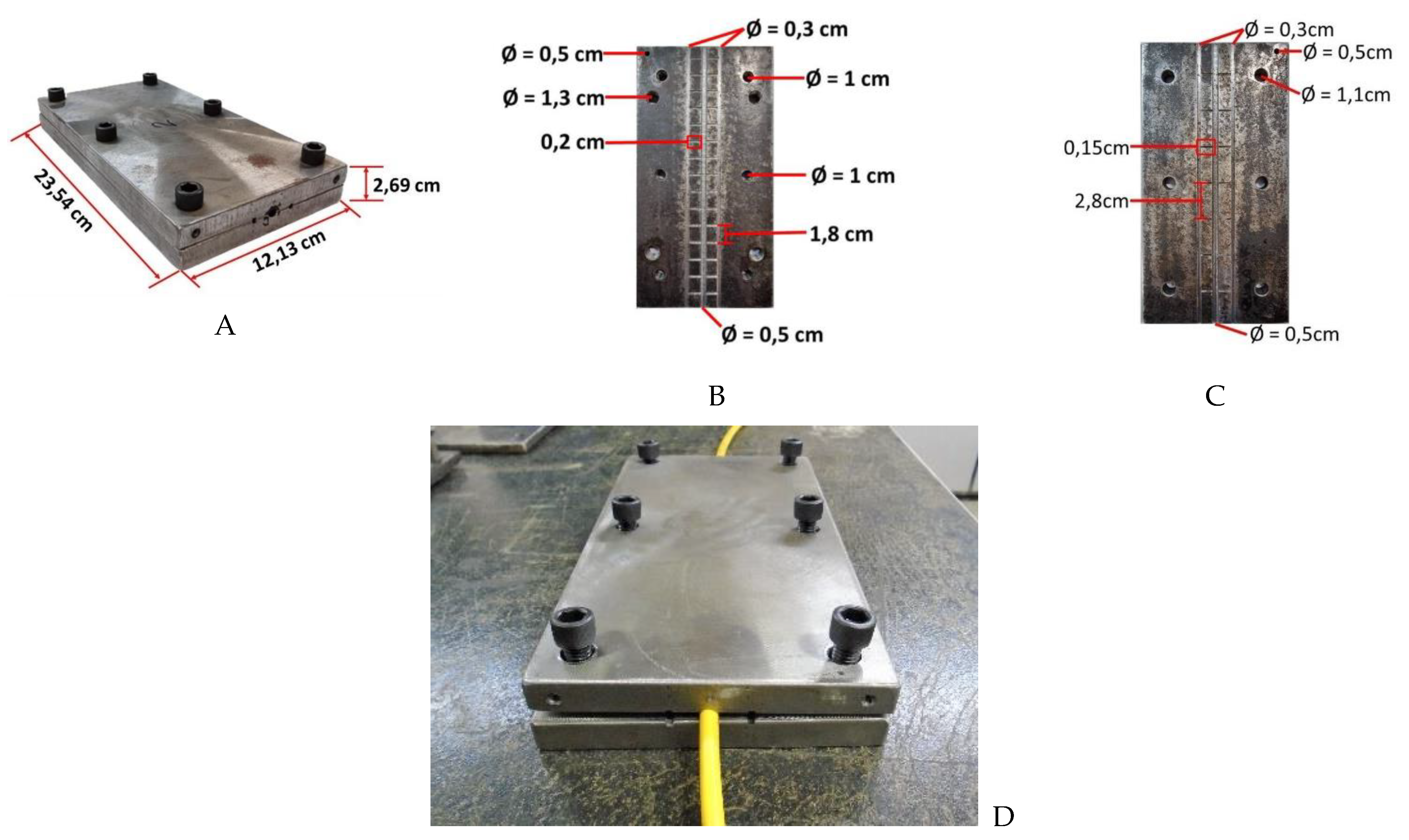
Optical cable anchoring system was developed for the cable tensile test. It is important to point out that this development was carried out exclusively based on experimental tests tentative carried out until obtaining what is presented here. When the loss of optical signal was perceived with the cable pressed, the anchoring system was reassessed until reaching the dimensions shown below. There is no knowledge of a similar development since it can be said that it is a very personal development and according to the dimensions of the fiber optic cable, which have different characteristics according to the purpose of application. It is known that fiber optic cable manufacturers have cable calibration systems, however, these procedures are still confidential since attempts were made to know them, which was not possible.
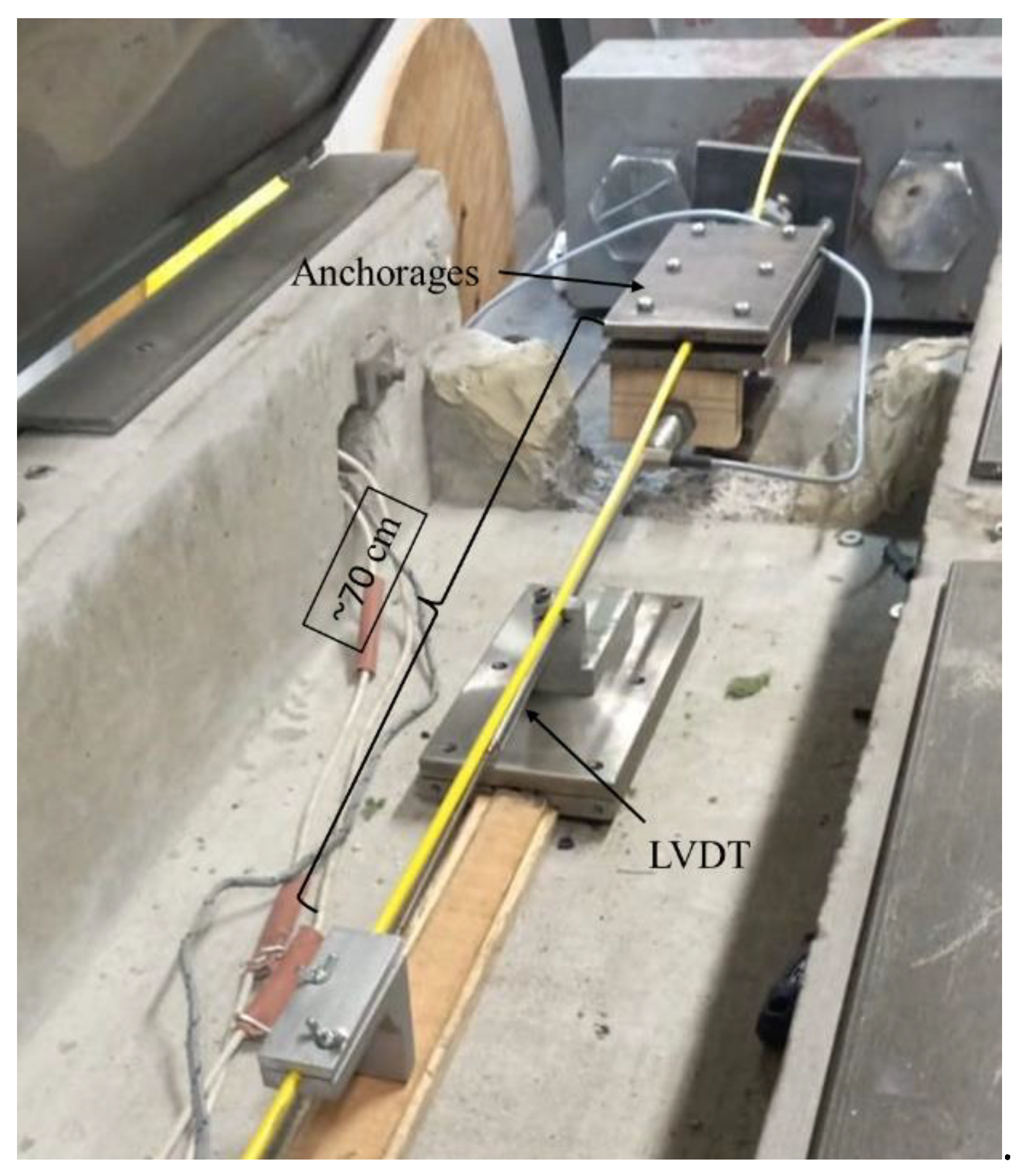
The system used consists of two rectangular metal plates, measuring 23 cm by 12 cm on each side and 1 cm thick. The plate has a recess with roughness for the positioning of the cable with a diameter slightly smaller than the diameter of the cable. This system is installed at both ends of the cable on the test bench. In
Figure 5 are shown the photographs of this system.
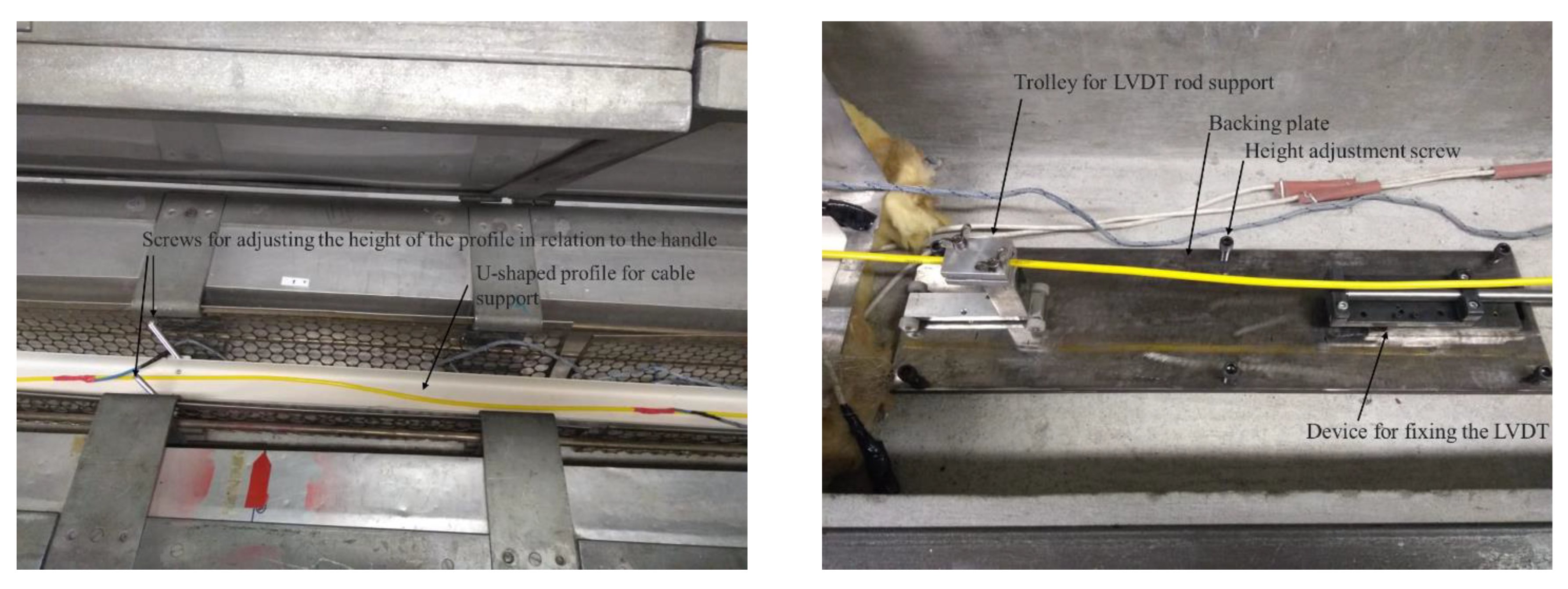
For the positioning of the LVDTs sensors, a support plate was developed that allows adjusting the height of the sensors in relation to the cable. On this plate there is an LVDT fixation system and a trolley to support its rod. This trolley is built on wheels, so that friction when moving the cable is minimized. Figure 8 shows an image of this system.
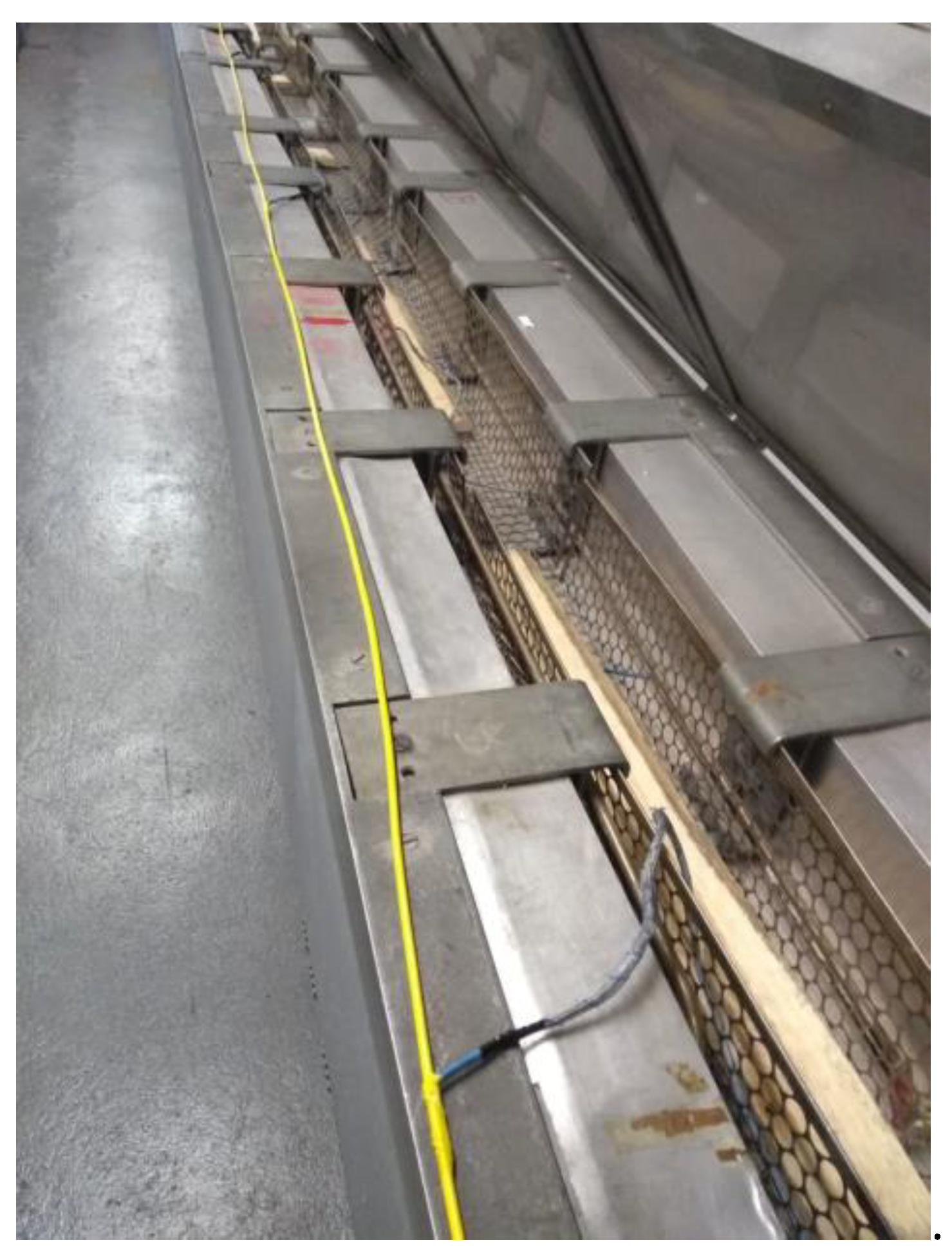
To support the optical cable, a U-shaped metallic profile was developed with screws along its length that allow the height of the profile to be adjusted in relation to the height of the optical cable, thus preventing the cable from being deformed by its own weight.
Figure 6 illustrates a section of this system.
3.4. Bench details
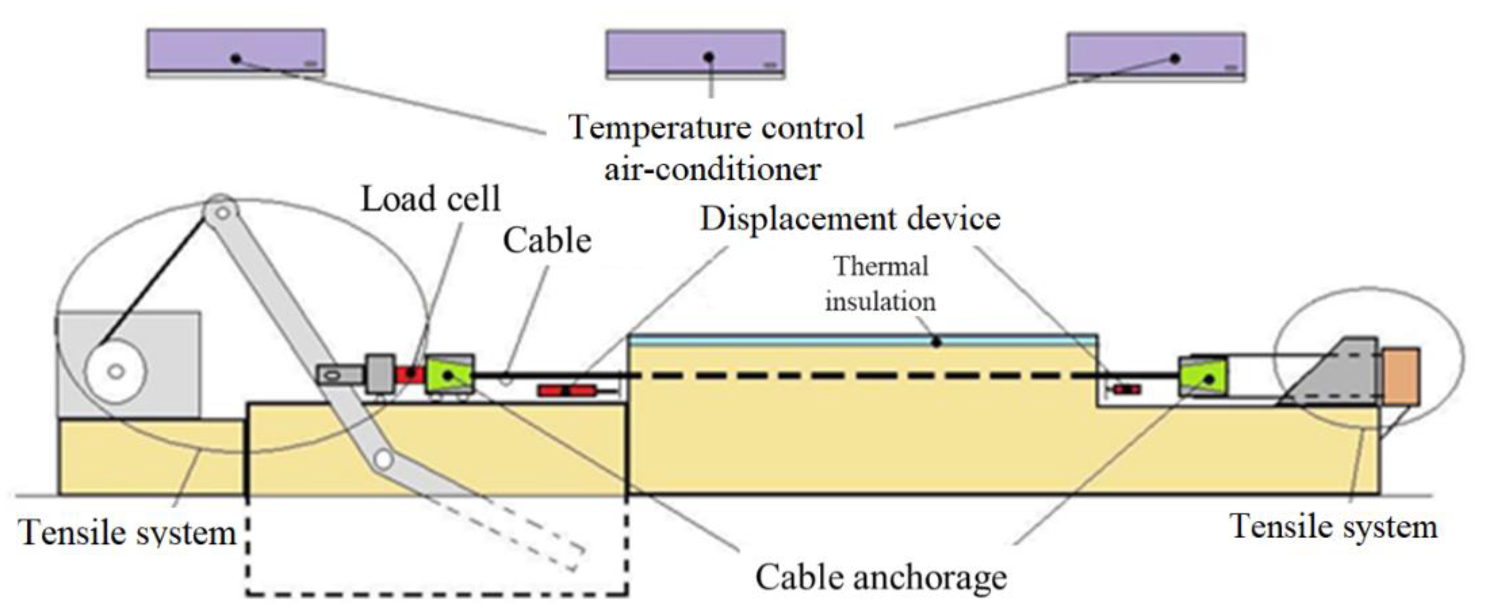
The calibration bench used is 14 m long and it can perform tests with tensile of up to 200 kN and with a total stroke of up to 1,500 mm in length. The bench's tensile equipment is equipped with a tensile control system, whose physical components are a servomotor and a reducer.
Signals from all force, displacement, and temperature transducers are stored on an NI SCXI 1000 datalogger and HBM's MGA II. The microcomputer receives the measurement readings through a PCI-6289 card, from National Instruments (NI), connecting an internal PCI bus to a microcomputer. This board also performs the function of sending temperature control signals to the air conditioners and tensile signals to the servomotor.
With the automation of the entire process, operator interference during tests is minimized, contributing to the uniformity of procedures. All measured data and control parameters are acquired and analyzed in real time, with graphic presentation. The test software was developed in LabView graphical language.
Figure 7 shows the schematic drawing of the workbench.
3.5. Test bench preparation
The sensor monitoring data (LVDTs, load cell and thermocouples) were collected in the same time interval as the optical interrogators, through a routine developed in LabView. Special care was taken to activate the equipment together and have an achieve synchronization. The times of the three acquisition systems (test bench, DTSS and DSTS) were synchronized. The strain increments were programmed for a strain variation of 15,000 με with a time interval of 9 minutes for each loading. These values were defined according to the maximum tension supported by the anchorage system identified in experimental tests.
The loads were performed by the person responsible for the test, while the sensor recordings were performed automatically. The temperature control (air-conditioners) of the room where the tests were performed was also automatically controlled by the developed program in LabView.
To start the test, the cable was completely relaxed on the platform of the test bench and then a manual adjustment of the engine displacement was performed until the strain variation was perceptible in the DTSS optical interrogator. At this moment, the deformation value in the cable was noted, which was around 1,700 με, in the section of the cable under test.
Figure 8 shows the initial condition of the cable, with the cable without strain applied.
After the mentioned adjustments, the test was started with strain in steps of 1,500 με until reaching the value of 15,000 με. These strains were controlled based on the displacements measured by the LVDTs. For each of the three programmed test temperatures, 20 °C, 30 °C and 40 °C, three repetitions were performed. In the third repetition of each temperature, the test bench was programmed to reach a value of 20,000 με, the deformation limit value read by the optical interrogators.
3.6. Test procedure
The procedure for carrying out the tests are described below.
Figure 9 shows a sketch of the test layout for the optical cable calibration, indicating the minimum length of each section. It can also be seen in this sketch that a single cable is connected to two optical interrogators, simultaneously, in the DTSS (BOTDR) and in the DSTS (BOTDA). This connection is possible due to the two single-mode optical fibers of the cable used in the tests (blue and orange fibers). This test configuration is not common, however, the purpose of using two interrogators was to verify if the calibration parameters obtained using different equipment used simultaneously in the tests were similar.
It should be noted that the minimum lengths indicated in
Figure 9 were based on the DTSS interrogator acquisition system (BOTDR), where the spatial resolution is approximately 1 m. For smaller spatial resolutions (BOTDA system), the minimum lengths may be smaller and must be evaluated on a case-by-case basis.
For the optical cable calibration tests, a cable length of approximately 60 m was required. For the BOTDR system, the optical cable is connected to the optical interrogator, then a cable section must pass through a temperature reference section. In this reference section, the deformation and temperature of the cable must be known. Thus, a section of loose cable (without deformation) is submerged in water at a known temperature (ambient temperature), so that during the tests the temperature variation in this section is minimal. On the test bench, approximately 13 m of cable were installed. For each section of the cable (interrogator to the reference; reference to the test bench and test bench to the end of the cable), it is recommended to leave a length greater than 5 m so as not to interfere with the reading section. For the BODTA system the cable still needs to return to the interrogator, so approximately 20 m more cable is needed.
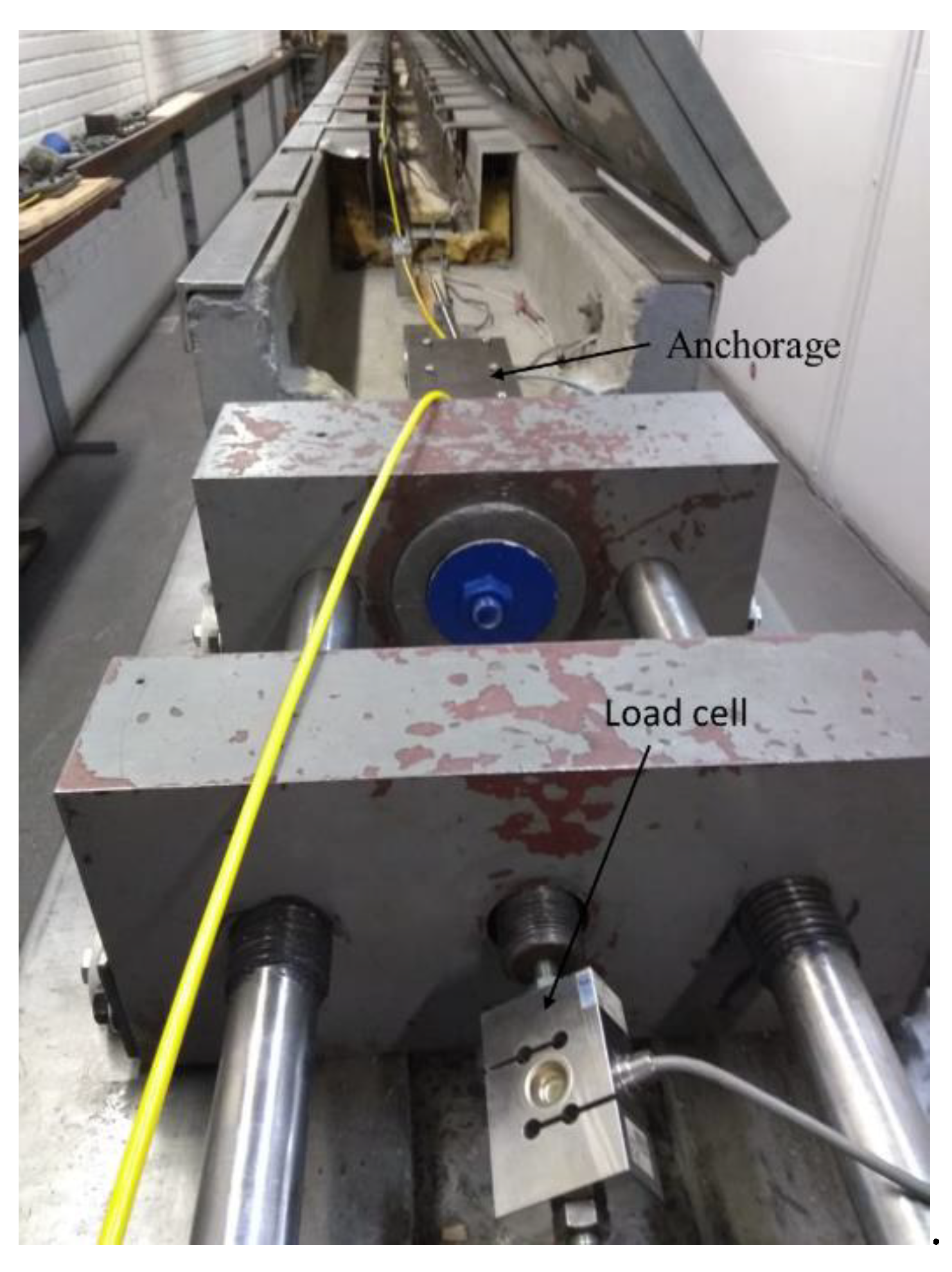
After positioning the cable on the test bench, the anchoring systems, displacement transducers and temperature sensors are installed on the cable. A load cell is installed on the bench for measuring tensile forces during calibration tests.
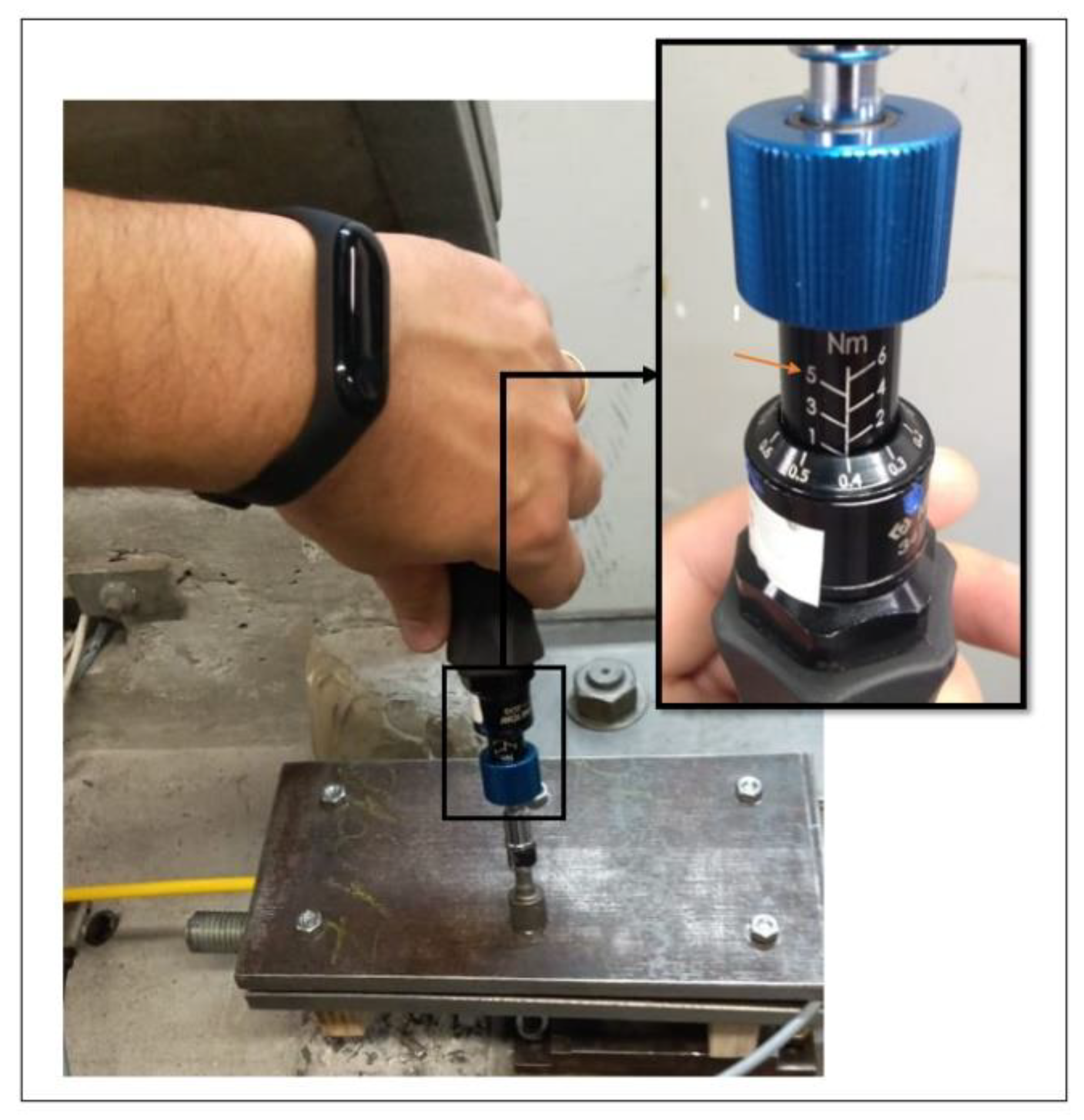
To install the anchoring systems on the cable, six screws from the system are tightened little by little and alternately. During the tightening of the screws, the torque was measured with the aid of a torquemeter. In previous tests, it was verified that the minimum torque applied so that the cable does not slip during tensile and the optical loss is minimized, should be 4.5 N.m.
Figure 10 shows the torquemeter used to install the anchoring system on the cable. It should be noted that the torque value indicated in the figure in question is only illustrative, not being the value used to tighten the screws for installing the anchoring system.
The displacement sensors (LVDT) were installed at approximately 11.6 m from each other and at 70 cm from the cable anchorage. Therefore, to calculate the strain, the distance between the displacement sensors is used and it was not used the distance between the cable anchorages (
Figure 11).
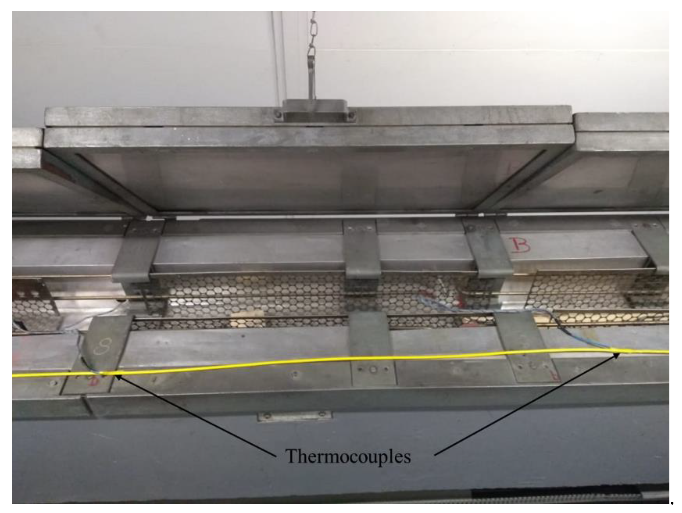
Seven temperature sensors (thermocouples) were installed on the cable, spaced every 1.80 m from each other. The sensors were fixed with the aid of self-fusion adhesive tape. These sensors help control the activation of three air conditioners used to maintain a constant temperature in the room where the tests were performed through an interface developed in LabView.
Figure 12 shows two thermocouples installed in the optical cable for monitoring temperature control during the tests. The load cell was installed between the test bench tensile system and the optical cable anchorage, as can be seen in the
Figure 13.
The temperature control of the test bench, which was carried out with the aid of three air conditioners and an electrical resistance, equivalent in length to the length of the cable, installed inside the bench. The temperature was monitored by the average of the 7 thermocouples installed along the length of the cable. The increase in temperature, to meet the range of 20°C to 50°C, provided for in the tests, was carried out in steps of 3°C, every 12 min. In the calculations, the temperature of the cable in the final 3 min. of each step was discarded, as in this time interval the addition to the next test temperature step was carried out.
Thus, the stabilization of the room ambient temperature at 20°C was carried out, with the aid of air conditioners. This stabilization was scheduled by a day before each test. Up to the temperature of 26°C, only air conditioners were used for heating. For the other temperature levels, the electrical resistance of the bench was used, until the test limit temperature of approximately 50°C was reached. It should be noted that both for the air conditioners and for the electrical resistance, the temperature control was carried out by the computer program developed in LabView.
The optical interrogators were configured to record strain measurements simultaneously over a 3 min. time period. This time was based on the interrogators' minimum acquisition time. For DTSS, the minimum acquisition rate defaults to 2 min. and the spatial resolution are 1.0202 m. For DSTS, the acquisition rate depends on equipment configuration parameters, such as: light pulse length (10 ns) and spatial resolution (0.32 m); number of scans to obtain a measurement (10,000); and frequency increment between successive sweeps (5 MHz). With the values indicated in parentheses, the minimum acquisition rate was 3 min. Therefore, both interrogators were programmed to take a reading every 3 min.
4. Data analysis
This item shows the analysis and discussion of the results of nine tests carried out to determine the optical calibration parameter of the optical cables. The tests were carried out at three different ambient temperatures, 20°C, 30°C and 40°C, which are expected temperatures for operating conditions.
For each temperature, the tests were repeated three times, thus, nine tests in total as mentioned. The tensile force was monitored in the tests only to control the maximum tensile force supported by the cable, 3 kN. In this article, the results of this monitoring are not presented.
The determination of the optical cable calibration parameter for deformation measurements was carried out by linear regression, where the variations in the frequency of the Spectrum of Brillouin are correlated with the variations of the deformations imposed on the optical cable, read from displacement sensors (LVDTs).
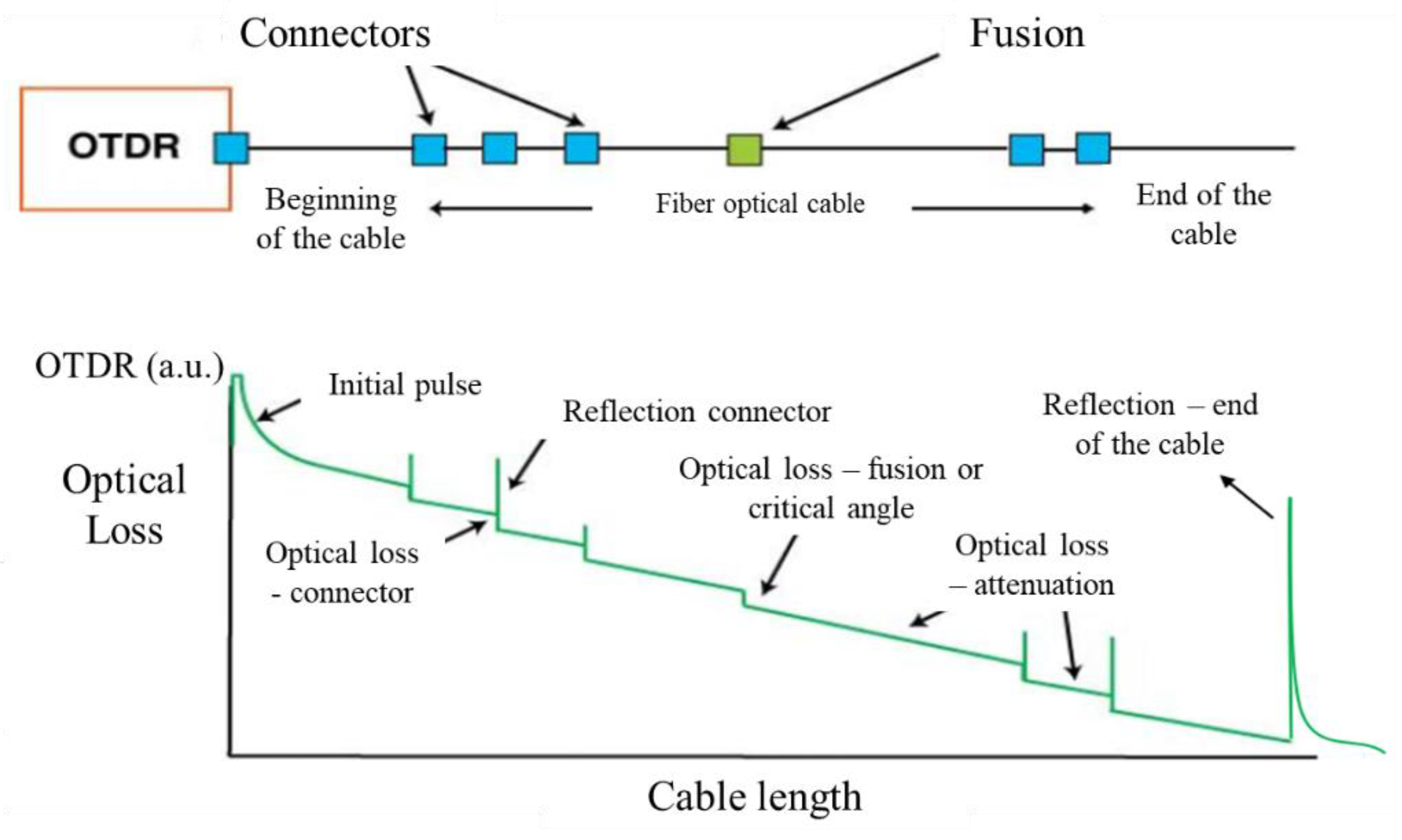
Prior to the calibration tests, an analysis of the optical loss caused by crushing the cable in the anchoring systems was carried out. The optical loss is graphically analyzed based on the response of the OTDR (Optical Time Domain Reflectometer) signal, where it is possible to identify and quantify the signal loss in an optical cable.
Based on experience using the equipment, it was verified that the OTDR signal level, in order to have a good result, must be greater than 0.25 a.u. (astronomical unit), where the value 1 a.u. indicates that 100% of the signal is being transmitted, that is, there are no optical losses and, value corresponding to 0 a.u. indicates that there is no optical signal being transmitted, that is, total optical loss, which can be caused by critical angle or identification of the end of the optical cable.
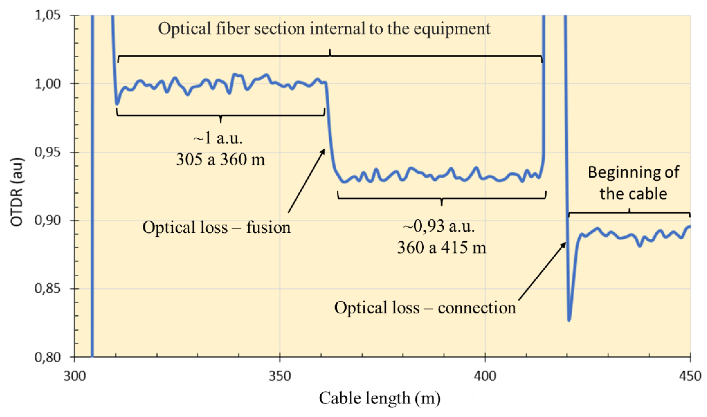
Figure 14 shows the conceptual interpretation of the OTDR response signal, where the vertical axis represents the OTDR value and the horizontal axis the cable length. The slope of this plot is the natural attenuation (optical loss) along the length of the cable.
OTDR analyzes were performed only with the Sensornet DTSS interrogator; in the DSTS equipment from OZ Optics, it is not possible to perform this type of analysis. Inside of the DTSS interrogator there is a section (stretch). This section is coming from the factory. It is approximately 415 m. Between sections 305 m and 360 m, the OTDR signal has 100% of the signal (1 a.u.); in the 360 m length there is an optical loss resulting from a splicing of the optical fiber carried out along the installation, where the signal decreased to 0.93 a.u. up to length 415 m. From length 415 m, the OTDR signal is from the fiber that is connected to the equipment. It should be noted that the splice inside the equipment is performed due to the hardware connections of the equipment itself, it is not a fiber that was broken and spliced for repair.
Figure 15 shows a graph based on the comments made in this paragraph.
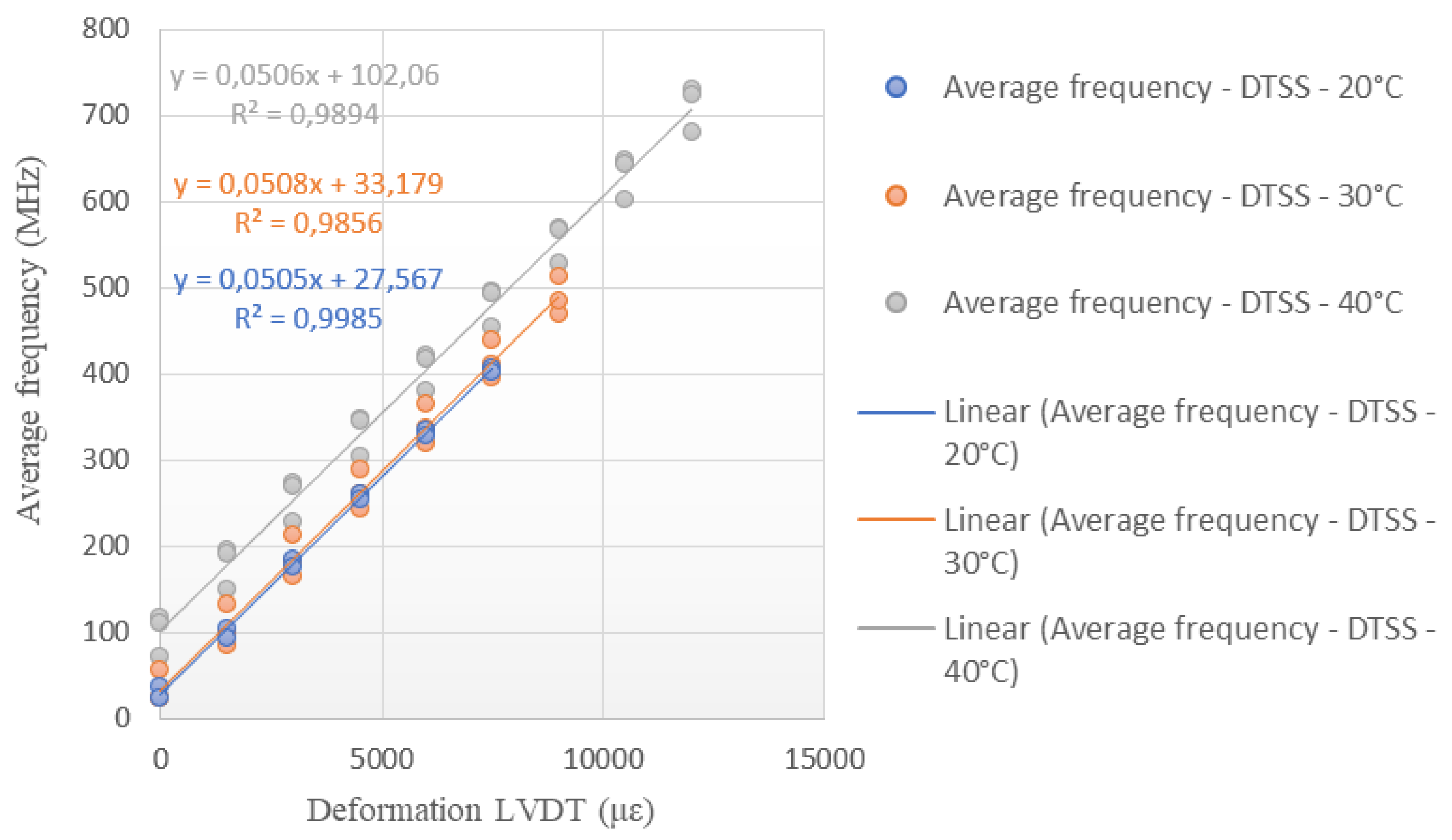
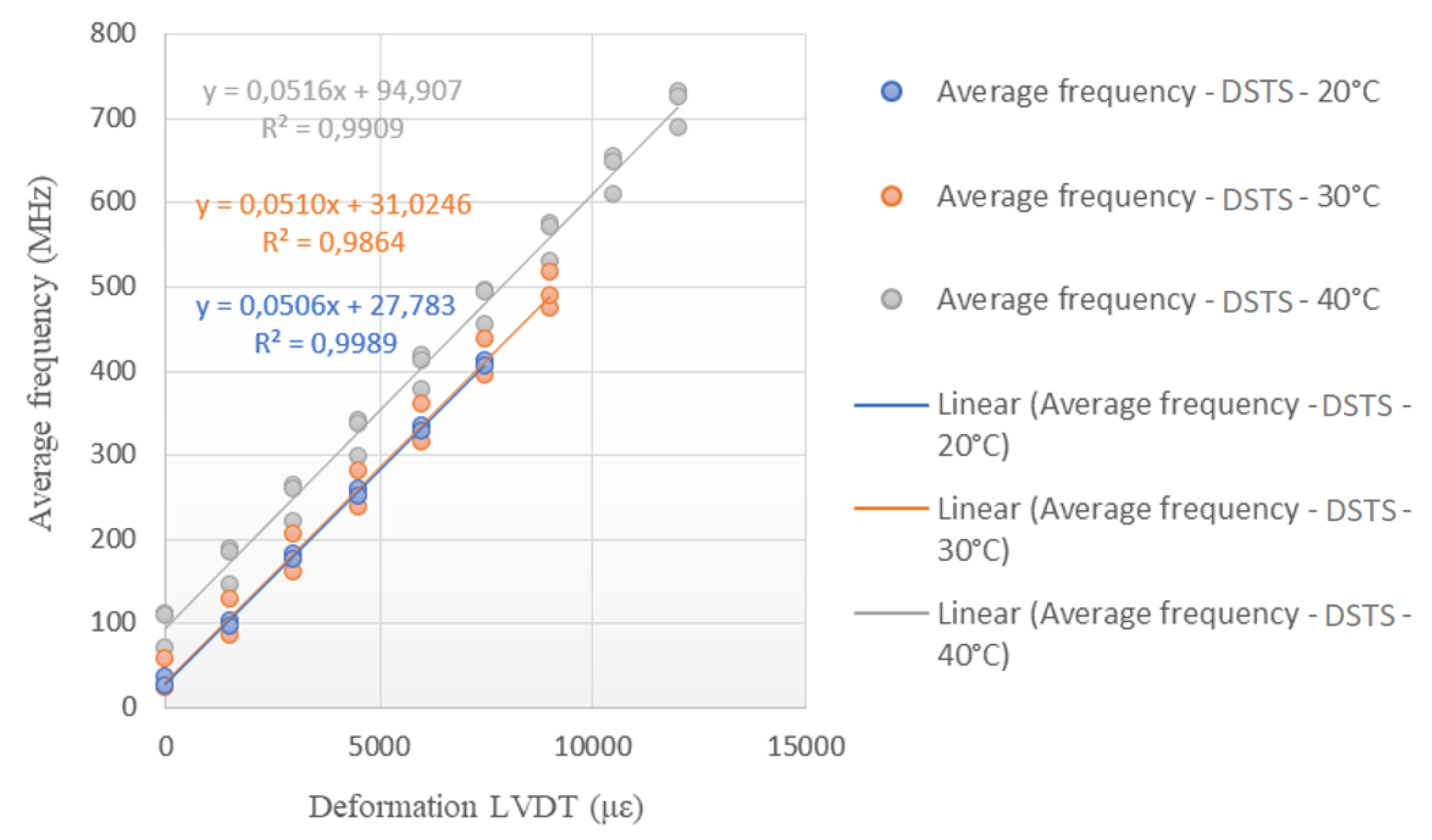
The graphs presented below show the Brillouin frequency on the vertical axis and the strain on the horizontal axis. The angular coefficient of the line obtained by linear regression is the optical calibration parameter obtained for the deformation measurements.
The following items present and discuss the results obtained in the tests carried out for the three programmed ambient temperatures of 20°C, 30°C and 40°C. For the calibration tests of the optical cable at different temperatures, the first step consisted of stabilizing the temperature of the laboratory. The average time for the temperature to stabilize at 20°C was approximately 1h, for 30°C, 1.5h and 40°C, 2h.
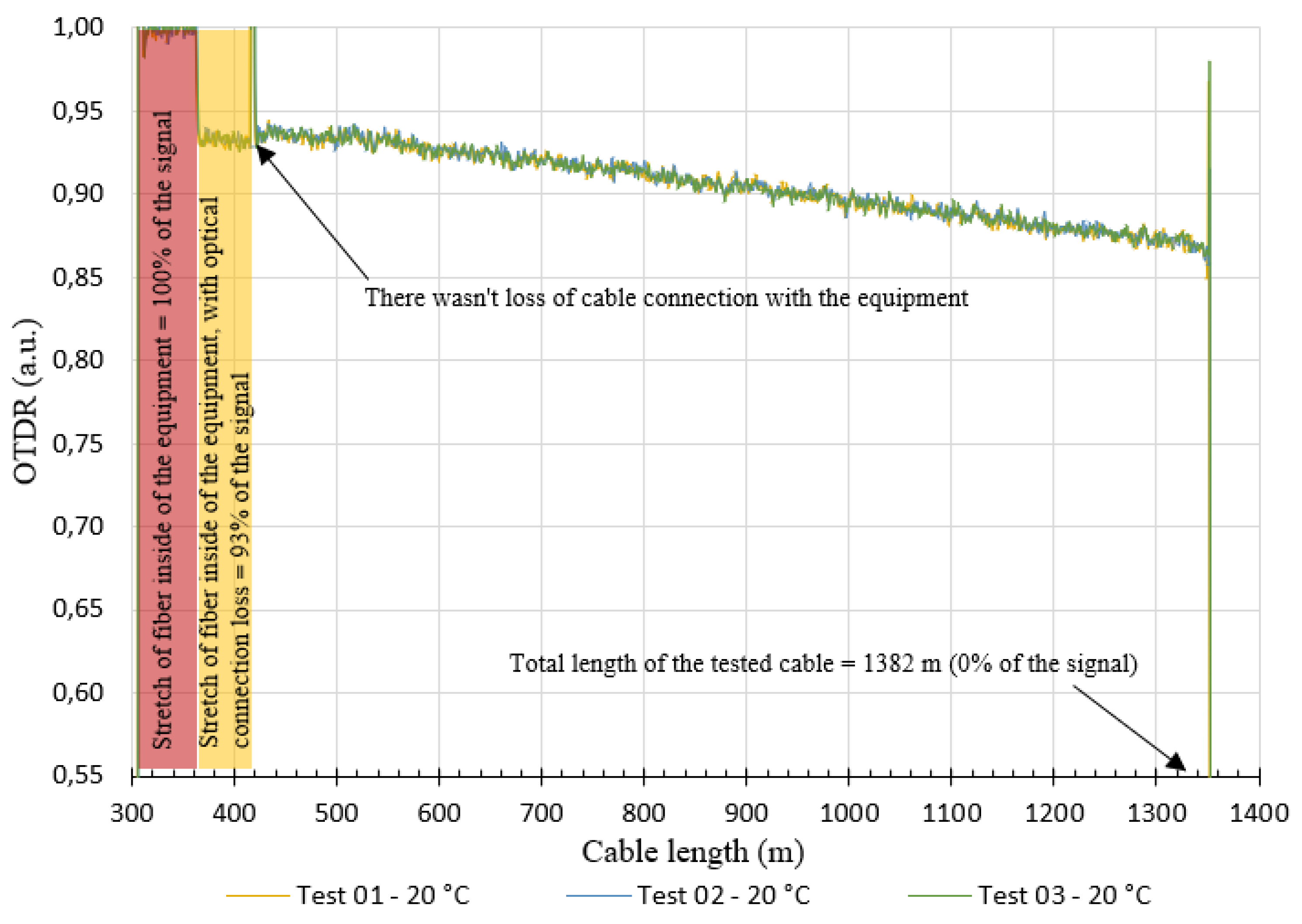
After the temperature stabilized, the test started with the verification of the response of the OTDR signal. The graph in the
Figure 16 shows an example of the result obtained from the OTDR response at the beginning of the test for the three tests carried out at a temperature of 20°C. Evidently, these analyzes were performed for all tests.
Based on the graph shown in Figure 19, it is possible to observe that there was an optical loss at the two cable anchorage points (lengths from 300 m to approximately 420 m). The cited optical losses ranged from 0.93 a.u. and 1.00 a.u. did not make the tests unfeasible, as they have values greater than 0.25 a.u (ideal OTDR value for the tested cable length). It is also noted that the optical loss is greater in the first test and decreases in the second and third tests. This reduction in optical loss is probably due to the rearrangement of the fibers inside the cable after its tensile, since the same stretch of cable is used in the tests.
After verifying the response of the OTDR signal, the test was then started, applying controlled deformations for the frequency measurement. Three tests were carried out at the same temperature in order to obtain the cable calibration parameter for strain measurements using the DTSS interrogator and the DSTS interrogator. The parameters were obtained through linear regression of the average of deformations controlled by LVDTs and the variation of the frequencies obtained.
Tensile tests
This item presents the results of tensile tests performed on the bench presented in item 3.4. Tests were carried out on the fiber optic cable produced by Furukawa (Brazilian cable) and by Sensornet (UK cable). The tests consisted of varying the temperature and strain to be possible to compare the parameters obtained (angular coefficient).
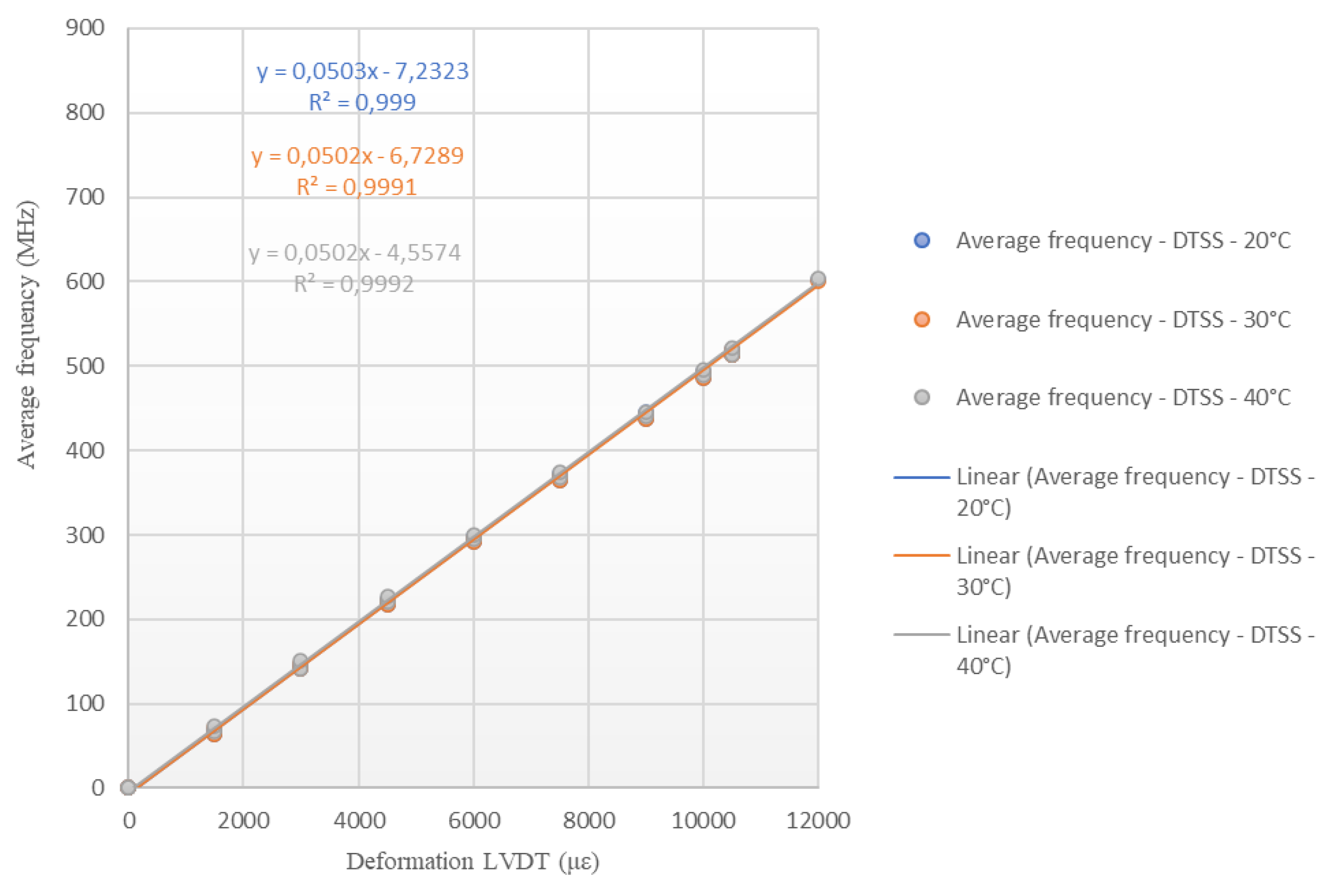
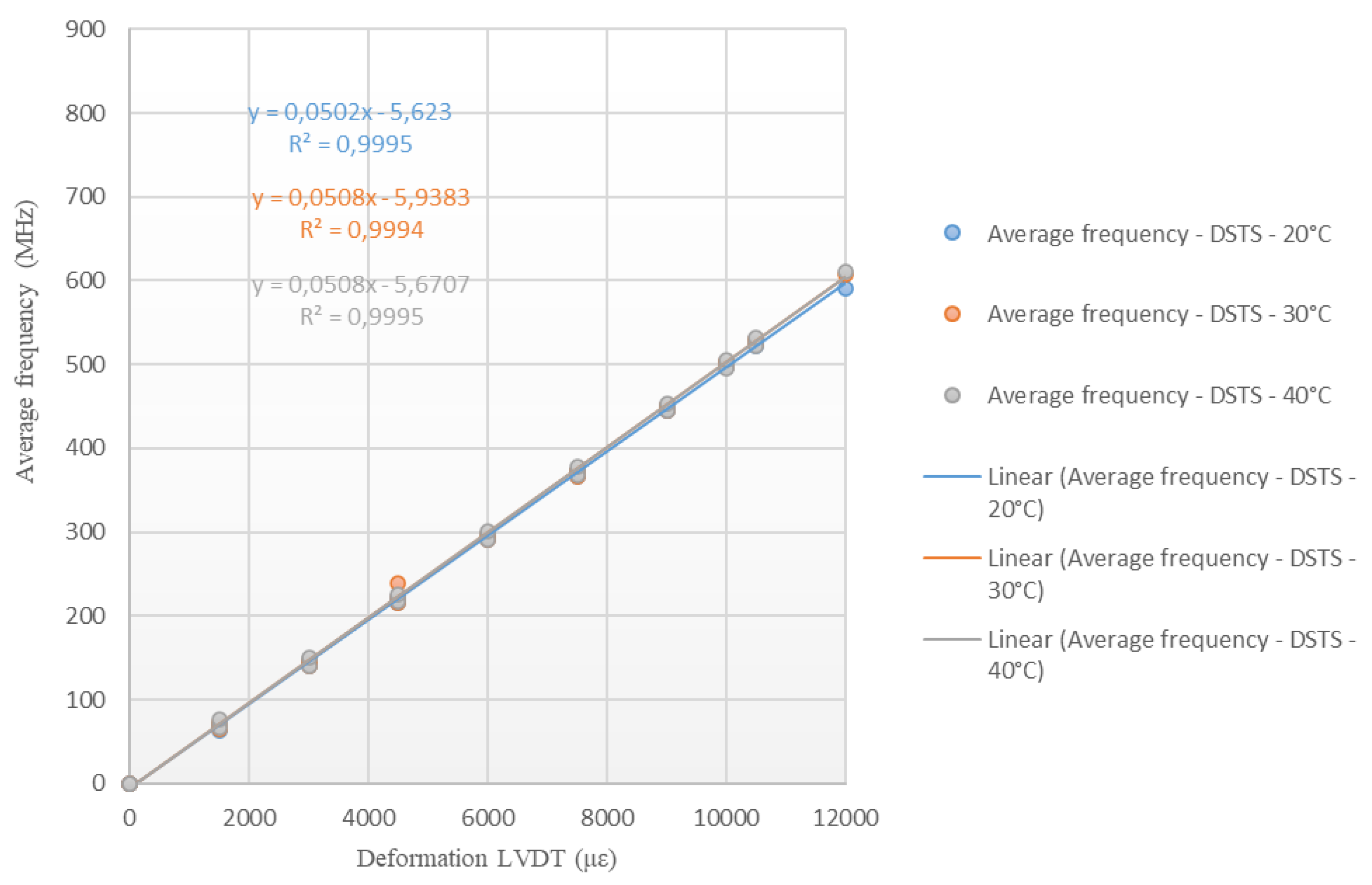
Figure 17 and
Figure 18 show the results obtained from carrying out deformation tests for different ambient temperatures (20°C, 30°C and 40°C) with the cable produced by the company Furukawa. The tests were performed with the DTSS and DSTS interrogators. The results are presented in terms of deformation versus monitored frequency.
It is important to emphasize that, for the analysis of the results, it is not necessary to impose an offset. Changing the data with the line passing through the origin will evidently change the calibration coefficient. The readings are interpreted from the variation of the frequency of the Brillouin Spectrum, thus the coefficient “b” of the equation y=ax+b is annulled. The value used is just the “a” coefficient. The tests were conducted at different temperatures to assess whether the variations would influence the calibration parameters.
Based on the calibration parameters obtained in the tests (Figure 20 and 21),
Table 2 was prepared to show the results comparison. Using the calibration equations obtained, the Brillouin Spectrum frequency was varied between 0 and 1000 MHz, for each test conditions (20°C, 30°C and 40°C) and for each interrogator (DTSS and DSTS). In the Table, the “DTSS Difference” is the sub tensile between the largest and smallest deformation obtained for the tests carried out with the DTSS interrogator; the “DSTS Difference” is the sub tensile between the largest and smallest deformation obtained for the tests carried out with the DTSS interrogator; and the “DTSS and DSTS Difference” is the sub tensile between the largest and smallest strain obtained considering both values obtained by the DTSS and DSTS interrogators. The highest and the lowest values obtained are highlighted in the table, in red and blue font, respectively.
Analyzing the results presented in Table 5, it is possible to observe that the highest variations in deformations occurred for the highest values of the frequency of the Spectrum de Brillouin; and that the highest deformations differences occurred for the DSTS interrogator. Therefore, the average parameter obtained for the DTSS interrogator is 0.0502 MHz/με, for the DSTS interrogator it is 0.0506 MHz/με and the average parameter between the interrogators is 0.0504 MHz/με. These variations may have occurred due to assay settings, even though the readings on the two interrogators took place simultaneously. In addition, for applications that are intended to be carried out in the field, the differences in deformations monitored by the different equipment are negligible.
For each temperature, the same stretch of cable was always used and the analyzes did not consider whether there is permanent/residual deformation due to cable tension. Another factor that may have influenced the results of the tests is the initial state of deformation of the cable. During the tests, the initial position of the press was not carefully controlled, it was only checked if the cable was loose at the beginning of the tests.
Also, the cable in the tests was suspended, without a support, which certainly causes an initial deformation due to its own weight. The fact that the cable does not have a support may also have interfered with the strain readings, which are measured in the LVDTs sensors, since there is a device attached to the cable for carrying out the tests. Those facts can explain the differences between the test results and the Sensornet calibration informed.
Figure 19 and
Figure 20 show the angular coefficients obtained in the tests carried out on the Sensornet cable for each of the temperature conditions of the tests (20 °C, 30 °C and 40 °C), with the DTSS and DSTS interrogators. These angular coefficients are the calibration parameters of the tested optical cable to obtain deformation data (LVDT) from the frequency of the Spectrum de Brillouin.
Based on the calibration parameters obtained in the tests,
Table 3 was prepared, like
Table 2.
Analyzing
Table 3, it is possible to observe that the highest variations in deformations occurred for the highest values of the frequency of the Spectrum de Brillouin; and that the highest differences in deformations occurred for the DSTS interrogator. Therefore, the average parameter obtained for the DTSS interrogator is 0.0506 MHz/με, for the DSTS interrogator it is 0.0511 MHz/με and the average parameter between the interrogators is 0.0509 MHz/με.
As in the previous analysis, it can be stated that the variations that occurred may have resulted from the test configurations. For each temperature, the same stretch of cable was always used and the analyzes did not consider whether there is permanent/residual deformation due to cable tension. Finally, it is believed that the cable construction process can influence the calibration parameter.
5. Final considerations
In this paper, results of two optical fiber cable calibrations are presented. Calibrations of single-mode fiber optic cables were carried out with DSTS (Oz Optics) and DTSS (Sensornet) interrogators. The results of calibration of tensile tests were performed on fiber optic cables sold by Sensornet and Furukawa. The results obtained were satisfactory and close, from then on, it is known that it is possible to monitor deformations with a single-mode fiber optic cable. It was also proposed a methodology for calibrating of the fiber optic cables deformation since the calibration parameters are provided by the cable manufacturers, which can result in errors depending on the application. There are few manufacturers of fiber optic cables aimed at application in civil engineering. Therefore, with the calibration methodology proposed in this paper, it is intended to transmit to the academic community the possibility of obtaining calibration parameters of any fiber optic cable, even those manufactured for telecommunications purposes and not only for cables manufactured with the intended use in civil engineering. Because of this fact, researchers will not be restricted to the acquisition of special cables for their applications.
For strains calibration, using the UK cable (Sensornet), the average calibration parameter obtained for the DTSS interrogator is 0.0506 MHz/με, for the DSTS interrogator it is 0.0511 MHz/με and the average parameter between the interrogators is 0.0509 MHz/με. The calibration parameter reported by Sensornet is 0.0481 MHz/με. For the Brazilian cable (Furukawa), the average parameter obtained for the DTSS interrogator is 0.0502 MHz/με, for the DSTS interrogator it is 0.0506 MHz/με and the average parameter between the interrogators is 0.0504 MHz /με.
Through the presented test arrangement, using different data acquisition system technologies, it was possible to obtain simultaneous readings of fiber optic and conventional sensors with compatible results between them, which allowed the calibration and verification of the performance of the different types of sensors, optical cables, and data acquisition technologies.
Based on the results, it is concluded that the application of calibrated fiber optic sensors in experimental piles foundations is viable, in order to evaluate the load-displacement behavior of these elements, under different loading conditions.
