1. Introduction
Cancer is the leading cause of death worldwide, with nearly 10 million people dying from cancer in 2020, accounting for almost one-sixth of the total global death [
1]. Early-stage and precise detection of tumor tissues is critically important, as timely cancer treatment can effectively reduce mortality rates [
1]. Recent studies suggest that the solid tumor progression typically increases collagen deposition and crosslinking within tissue stroma that deregulates and disorganizes the extracellular matrix (i.e., ECM, a three-dimensional assembly of macromolecules and interconnected cell-scale fibers) [
2]. Such changes in the ECM result in a modification in the biochemical and mechanical properties of cells, where many solid tumors are significantly stiffer than normal tissues. This phenomenon makes stiffness-based inspection (i.e., palpation) a relatively accurate but simple method to detect cancerous tissues, by which medical doctors can use their sense of touch to determine tumors [3-6]. However, touch sensing in humans is subjective; therefore, objective methods that employ digital sensors integrated onto endoscopes or medical robotics represent attractive features for tumor detection combined with robot-assisted treatment. The implementation of soft robotic palpation is expected to improve diagnostic efficiency and accuracy, and at the same time reduce tissue damage through minimally invasive procedures.
There are several types of tissue palpation devices with different structural configurations and sensing mechanisms. Among these, force [7-9] and pressure [10-13] sensors have been widely used to correlate the induced mechanical stimuli from the robot with the deformation of tissues to quantify tissue stiffness.
Table 1 lists some representative examples of palpation sensors for tissue-mechanic analysis. For instance, devices based on indentation depth use large and smooth contact surfaces to accurately measure tissue characteristics [
11,
14]. Sharp probe-type instruments, offer higher-resolution tissue stiffness features but can cause tissue damage due to their small contact area [
7,
15]. Arrays of tactile sensors with pneumatic devices for sensing, provide higher spatial resolution than single-point force feedback, and reduce tissue damage during contact [
16,
17]. In addition, tactile sensors that mimic the human finger structure can increase the accuracy of detecting hard nodules in soft tissue [
18,
19]. Furthermore, combining tactile sensing with wireless communication can eliminate the need for complicated wiring and electrical interconnect that can enhance robotic maneuver capability and reduce the incision size [
10,
20].
Despite the advances in tactile sensors, most available sensors were developed for dexterous robotic hands. The development of tactile sensors integrated onto endoscope and soft robotics remains challenging due to (i) the difficulty to install sensors on a small footprint, (ii) the requirement for mechanical flexibility to retain robotic maneuver within a small workspace inside the human body, and (iii) the need for optical transparency to allow real-time observation and assessment. For instance, using a Gamma force/torque sensor (ATI Industrial Automation Inc.) mounted on an aluminum rod (50 cm in length and 9 mm in diameter), Naish
et al. [
25] developed a minimally invasive system that can sense the normal and shear forces for tumor localization. However, the system lacks mechanical flexibility and therefore is not suitable for hard-to-reach organs (e.g., the colon track). Miki
et al. [
21] utilized liquid metal encapsulated in a three-dimensional (3D) microfluidic channel to develop tactile sensors. While the miniaturized sensor can measure contacting force and contacting directions, the use of non-transparent materials such as Galinstan and metallic electrodes can block the field of view of the endoscope that hinders image analysis capability. Yun
et al. used PZT bimorph to fabricate a tactile sensor that can detect tissue stiffness based on a shift in the resonant frequency of the sensor when it contacts tissues. The sensor was successfully mounted on a soft catheter robot and can measure tissues with different stiffnesses ranging from 0 to 2 MPa. Nevertheless, the use of PZT as the sensing element makes this device not suitable for an all-in-one system that can simultaneously enable mechanical measurement and optical analysis without using an additional optical path.
To overcome the above bottlenecks, in this work, we develop a novel soft, pneumatic tactile sensor for minimally invasive soft robotics. Experimental results demonstrate that the sensor can detect phantom tissue models with stiffnesses ranging from 0 to 2.5 MPa. The mechanical flexibility of the sensors allows for a simple integration onto soft robots, offering a high degree of freedom with different motions such as bending and linear actuations, suitable for hard-to-reach organs. The optical transparency of the constructing material (PDMS) enables real-time observation that can provide useful visual and mechanical feedback to detect and localize tumors.
2. Sensor Principle and Design
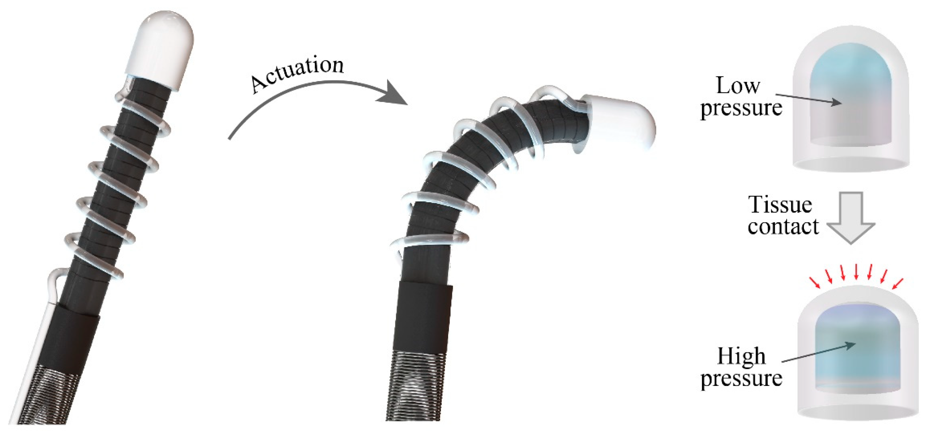
Figure 1 illustrates the configuration of a soft robotic system actuated by hydraulic soft microtubule artificial muscles (SMAM) and integrated with the proposed pneumatic tactile sensor. The tactile sensor is constructed by a transparent, dome-like air chamber and a commercial pressure sensing element (Amphenol ELVH-M500G-HRND-C-N2A4) connected to the chamber via a silicon tube. The silicon tube is wrapped around the SMAM tubes following a spiral shape to retain the mechanical flexibility of the system. This configuration (pneumatic sensing and hydraulic actuation) allows all electrical components (electric pump, control unit, and the pressure sensing element) to be placed outside of the patient’s body, while only mechanical parts (the hydraulic tube and the air chamber) are inserted through a small incision to reach the targeted organs. This approach will enhance the safety of the soft robot by minimizing the electrical contact between functioning electronics with the surrounding tissues.
The tactile sensor operates based on the change in the pressure level inside the air chamber when the robot contacts tissues. In particular, when the sensor is in contact with tissue, it will deform the PDMS dome that changes the volume of the air chamber, leading to a change in the pressure level (
P1/
P2 =
V2/
V1, where,
P1 and
V1 are the pressure and volume before contact and
P2 and
V2 are the pressure and volume after contact, respectively). Assume that
h is the displacement of the PDMS air chamber, the change in volume can be approximated as
Therefore, the change in the pressure level is expected to be a polynomial function of the applied displacement. The mechanical stiffness of tissues can be differentiated based on the measured pressure and displacement.
3. Sensor Development
3.1. Mechanical Part
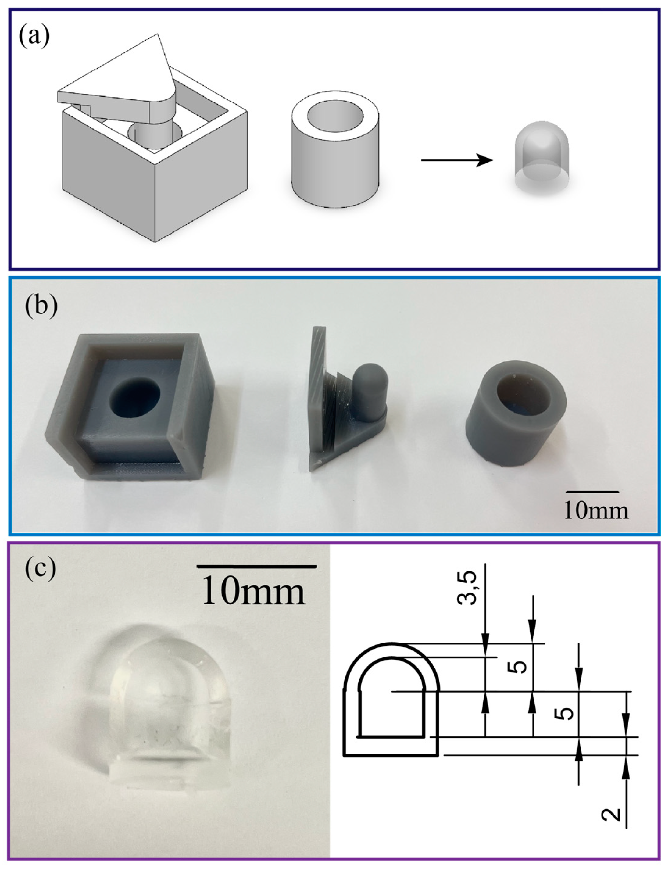
The air chamber (with a diameter of 10 mm, a height of 10mm, and a wall thickness of 1.5mm) of the tactile sensor was fabricated by casting PDMS (SYLGARD™ 184 Silicone Elastomer Kit with a mixing ratio of 10:1) to an SLA 3D printed mold. The mold consists of two parts, the housing and the upper cap which can be easily separated to detach the PDMS chamber from the mold. After the PDMS dome-like structure was vacuumed to remove air bubbles and then cured at 60°C for 2 hours, the air chamber was sealed by bonding the PDMS dome with another layer of PDMS film with a thickness of 2mm. An inlet was then punched from the bottom of the chamber to insert the silicone tube (with an inner diameter of 0.8mm, and an outer diameter of 1.6mm) and connect to the commercial pressure sensor,
Figure 2. The PDMS parts are elastic and hollow, which minimizes tissue damage when the robot interacts with targeted organs. The mechanical flexibility of the hollow structure combined with the low Young’s modulus of PDMS enables a large deformation of the chamber that results in a significant change in the inner pressure. The intrinsic optical transparency of PDMS avoids the issue related to field of view blockage in traditional silicon or metallic based sensors. This feature allows for real-time observation and visual feedback for the soft robot. The small footprint and electrical-wiring-free configuration are key features to ease the installation of the as-fabricated tactile sensor onto the tip of the soft robot. Integration of pneumatic soft sensors to hydraulic robot also retains the mechanical flexibility of the system as well as small incision size.
3.2. Readout Circuit
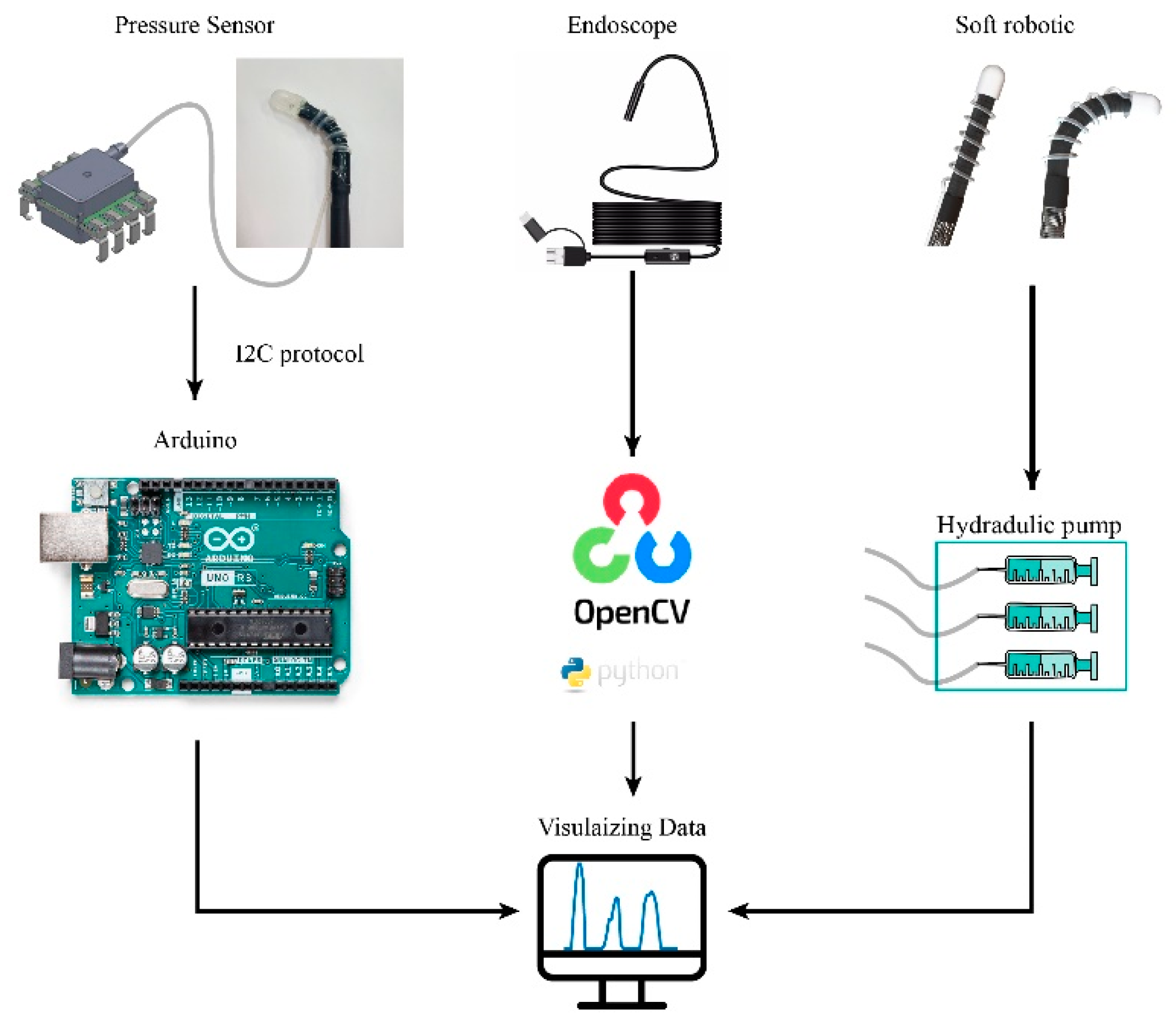
One side of the silicon tube was connected to the air chamber, while the other side was plugged into a commercial pressure sensor. The pressure sensor was connected to a controller (Arduino
TM Uno Rev3) that records and sends the measured data to a computer. An optical fiber was also placed underneath of the air chamber that can simultaneously observes and visualizes the inner tissues. We implemented automatic data acquisition from both the sensor and endoscope using Python programming. The digital signal of the pressure sensor is sent to Arduino via I2C bus, and the program transforms the original output voltage (in arrange of 0V to 3.3V) into the pressure value in mbar unit by the formula:
.The equipment connection layout and physical illustration are shown in
Figure 3.
4. Results and Discussion
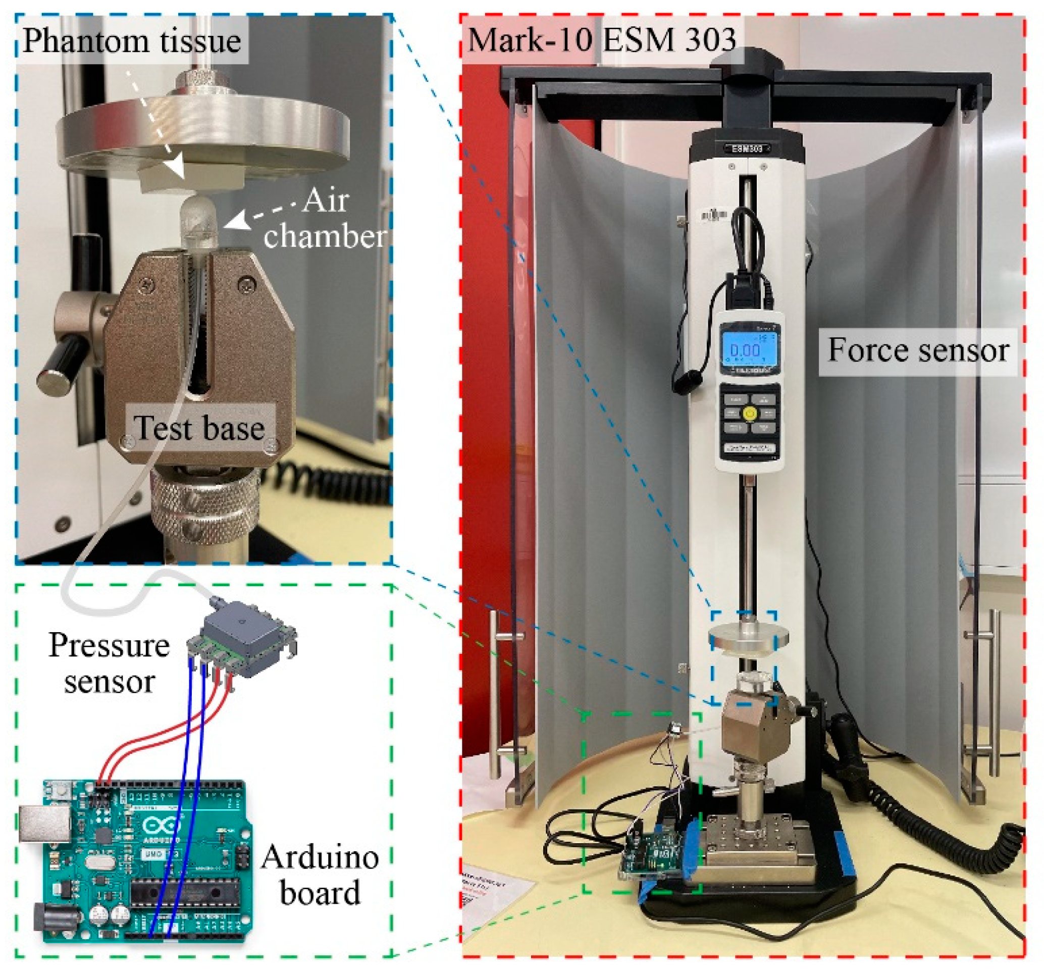
Figure 4 shows the experimental setup for tactile sensor characterization. We utilized a motorized tension compression setup (Mark-10 ESM 303) that can monitor in real-time the deformation (height) and applied force (Force Gauge Model M7-20). The tactile sensor was firmly fixed onto the lower base of the compression setup while phantom tissues with different stiffnesses were mounted on the upper metallic stage (iron) and pressed against the sensor. In the calibration experiment, a flat metallic surface was pressed directly against the tactile sensors so that all displacements are contributed by the deformation of elastic air chamber of the sensor. The sensor response (i.e., output pressure) and applied displacement was simultaneously measured, displayed, and recorded using an Arduino board.
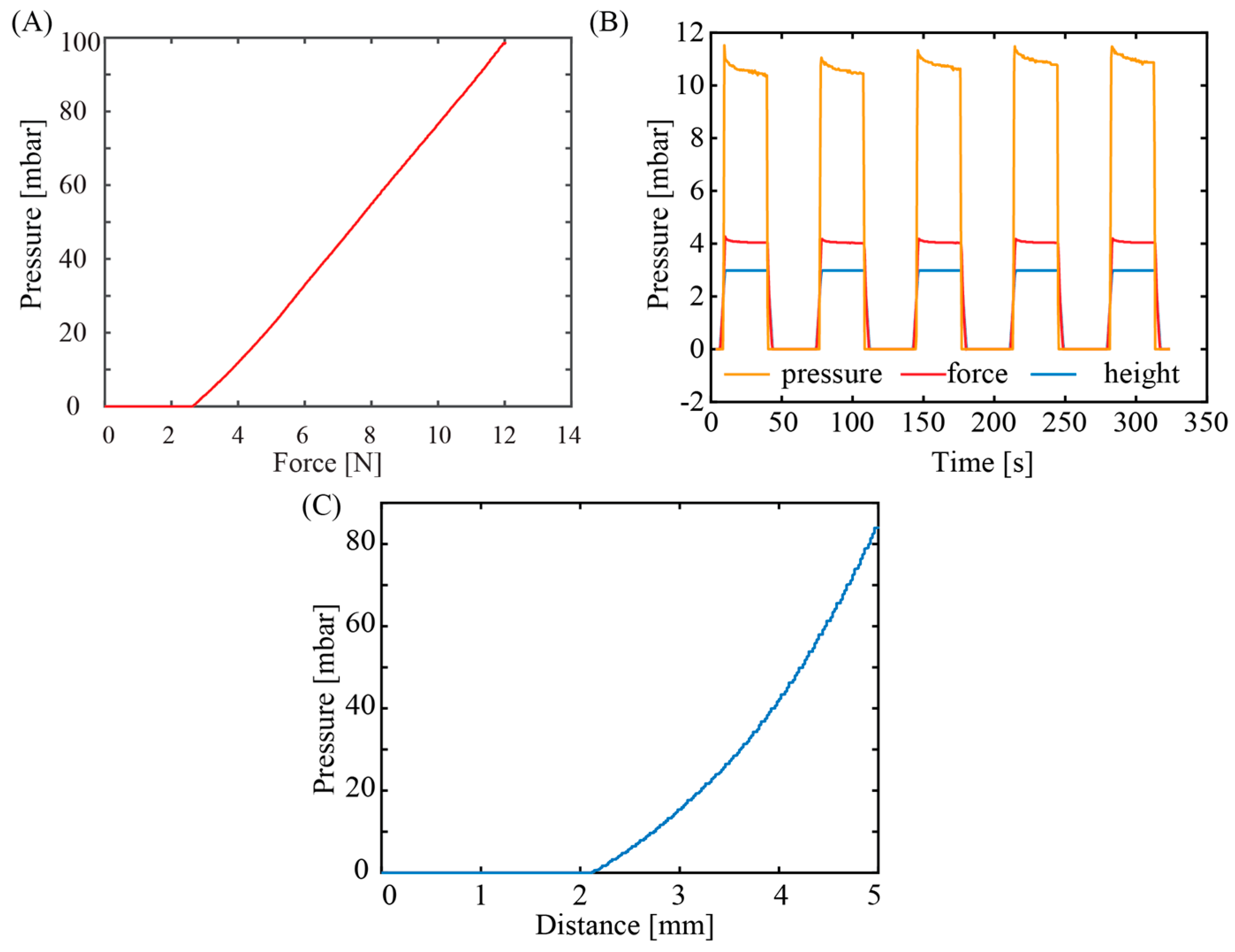
Figure 5A shows the response of the pressure sensor with varied applied force. The response of the sensors started to be observable at an applied force of 2N. The delay in the sensor output at this low force range can be attributed from the detection limit of the commercial pressure sensor along with the small volumetric change at the initial pressurizing stage. The sensor output linearly increases with increasing the applied force from 2N to 10N, a typical range used for palpation application. From this relationship, the applied force can be extrapolated from the measured pressure:
, which can serve as a feedback signal for robotic manipulation and palpation applications.
Figure 5B shows the output of the sensors at a constant applied force and displacement. Evidently, the tactile sensor exhibits a good repeatability and stability after several pressurize cycles, indicating that air was well sealed within the elastic chamber, the silicone tube, and the commercial pressure sensor. The tactile sensor did not show significant hysteresis once the applied pressure was released, indicating that PDMS air chamber can fully return to its initial shape owing to its excellent elasticity.
Figure 5C plots the relationship between the measured pressure and applied displacement, showing a polynomial relationship, which is consistent with the geometrical deformation shown in Equation (1).
Based on the stable performance of the tactile sensor to measure pressure again hard substrate, we further demonstrated its capability in differentiating soft materials with different stiffnesses. Three phantom tissue models were prepared by using Ecoflex™ materials with different elastic properties. The Young’s moduli of these phantom tissue can be estimated based on the relationship between Shore and ISO hardness (s) and Young's modulus (E) [
26]:
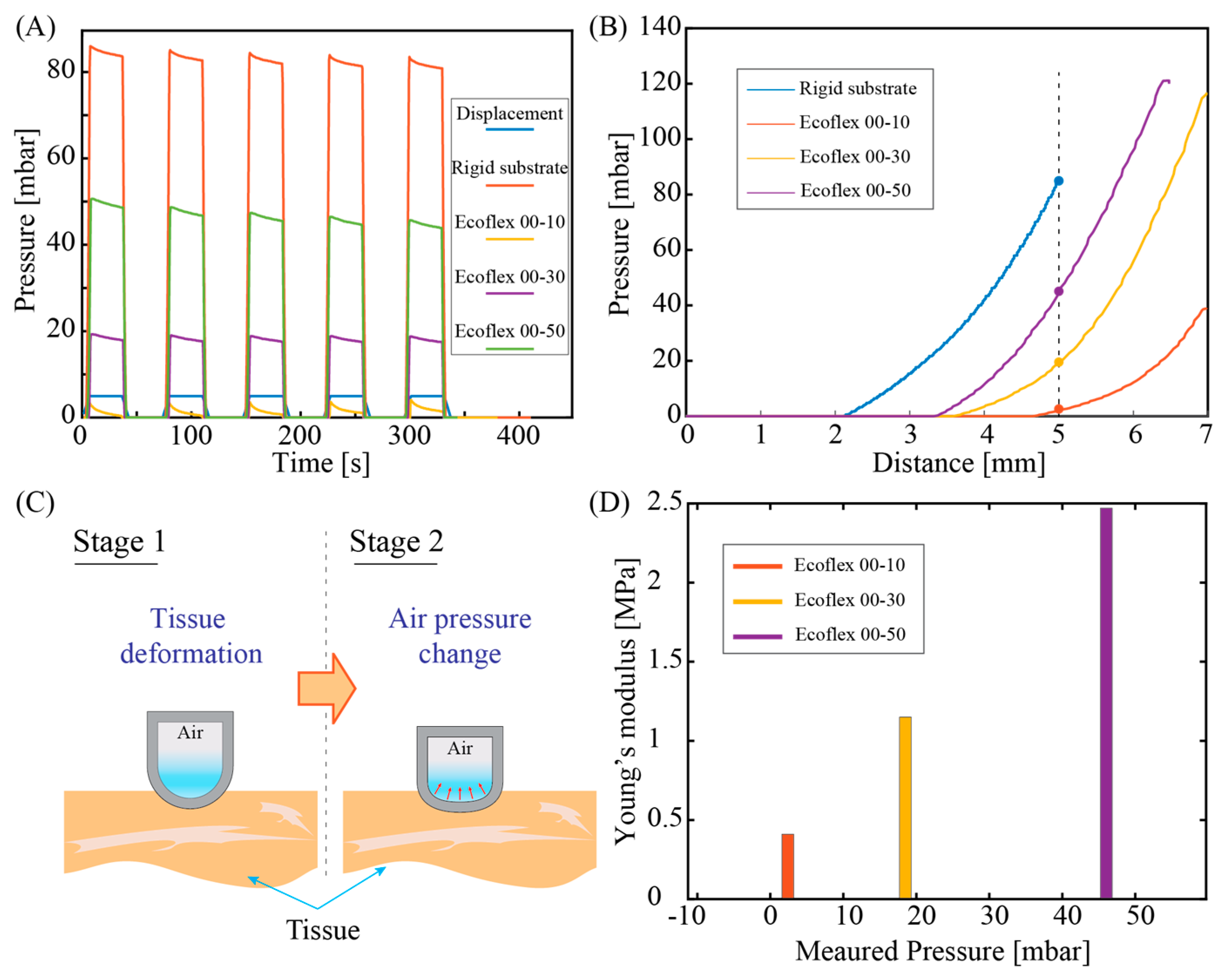
, where s is the Shore hardness . Accordingly, the approximate values of Young's moduli of Ecoflex™ 00-10, 00-30, 00-50 are 0.41 MPa, 1.15 MPa, and 2.47 MPa, respectively.
Figure 6A plots the response of the tactile sensor when applying the same displacement of 5mm to all three phantom tissues and the rigid substrate (iron). All cyclic pressurizing test shows a consistent sensor response with an output pressure of approximately 83.5 MPa measured for rigid substrate (iron), while these values for Ecoflex 00-50, Ecoflex 00-30 and Ecoflex 00-10 are 46.03 MPa, 18.5 MPa, and 2.4MPa respectively. Obviously, a higher-pressure level was observed in phantom tissue with a high stiffness (i.e., Ecoflex 00-50). To further interpret the relationship between the measured pressure output and the stiffness of the phantom tissue, we observed the transient response of the sensor when linearly increasing the applied displacement,
Figure 6B. For all three types of phantom tissues, the tactile sensor exhibits a similar trend that the change in pressure was only observable when the displacement reached a certain threshold. Specifically, for Ecoflex00-50 sample, pressure change is observable at a displacement of around 3.4mm, while this value for Ecoflex00-30 and Ecoflex 00-10 are 3.7mm and 4.7mm, respectively. We hypothesize that when linearly pressing the tactile sensor against the phantom tissues, the initial displacement was mainly contributed by the deformation of the tissue, as illustrated in
Figure 6C (stage 1 of deformation). When the tissues are compressed to a certain level, it will generate a sufficiently high elastic force (analogous to the spring force) that start to deform the air chamber in the opposite direction, resulting in a change in the air pressure,
Figure 6C (stage 2 of deformation). Since the elastic force is proportional to the spring constant of the testing sample, at the same applied displacement, Ecoflex 00-50 with higher Young’s modulus (2.47MPa) exhibits a larger force compared to those of Ecoflex 00-30 and Ecoflex 00-10 with lower Young’s moduli. As a consequence, it is reasonable that the pressure starts to change in the Ecoflex 00-50 (with a larger stiffness) first before the same phenomenon occurred in other phantom tissue samples. We extracted the measured pressure level of the three phantom tissue samples from the transient response at an applied displacement of 5mm. The relationship between the sensor response and the estimated tissue elasticity plotted in
Figure 6D shows a clear trend that phantom tissues with a higher stiffness exhibit a higher output pressure, which is consistent with the cyclic pressurizing results plotted in
Figure 6A. The data indicates the feasibility of using our sensor for quantifying the mechanical properties of biotissues.
5. Demonstration of the Tactile Sensor on Surgical, Soft Robot
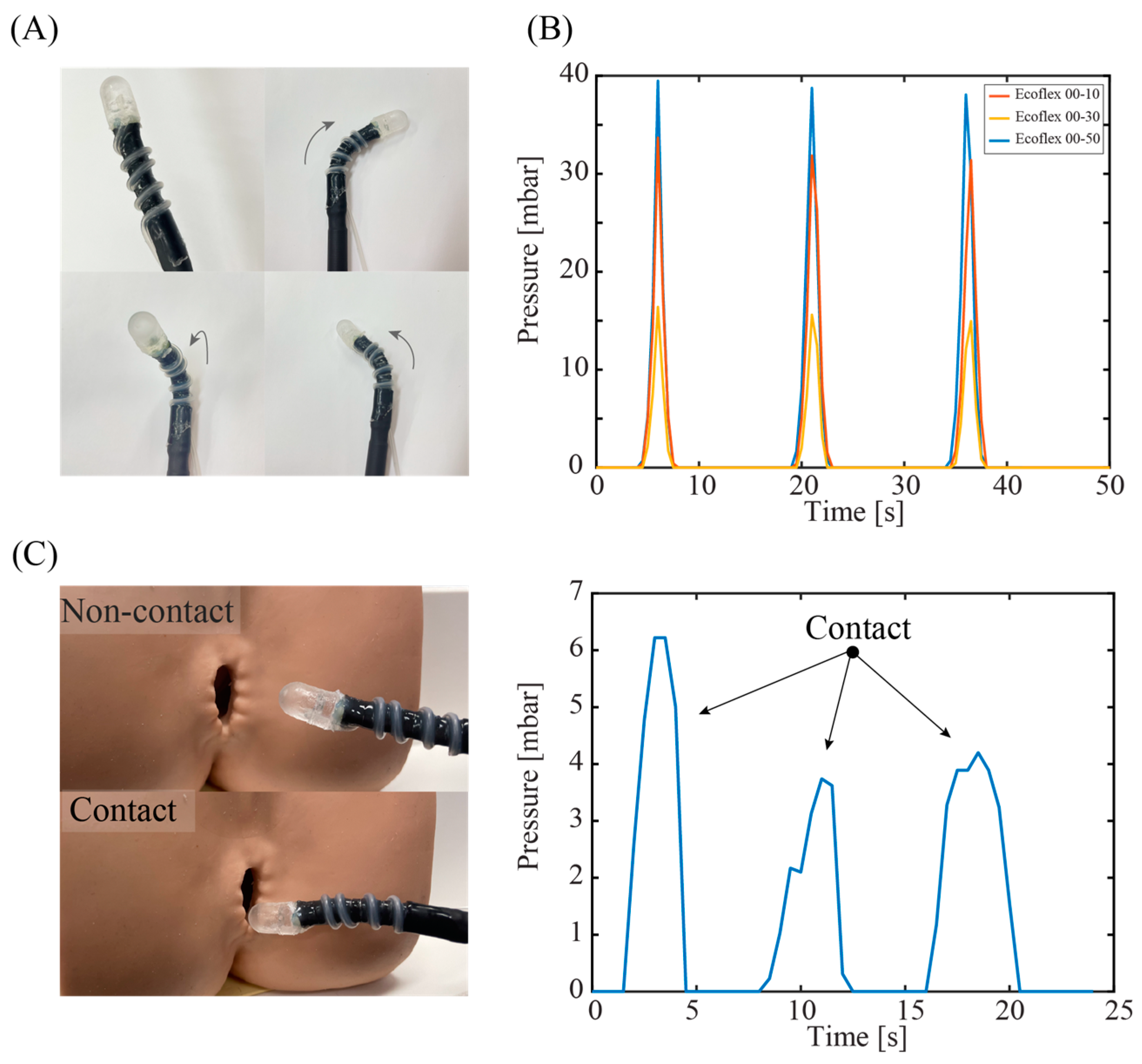
Figure 7A shows a photograph of a sensor-integrated soft medical robot, where the elastic air chamber is mounted on the top surface of the robot's end effector. The fluidic configuration (air) of the tactile sensor enables seamless integration with hydraulic soft robotics (liquid), where there is no direct electrical wiring posed to the inner tissue. The fabrication process and characteristics of our robotics system can be found in [
27]. The elasticity of the silicone tube retains the mechanical compliance of the system, allowing the robot to generate different actuations such as bending in left, right and out-of-plane directions,
Figure 7A. This high degree of freedom in robot motions is possible by using a set of three hydraulic tubes that can be independently or simultaneously actuated.
We demonstrated the capability of the soft robot in detecting tissues with different stiffness. Simultaneously actuating the three hydraulic tubes generates linear motion in the soft robot, which inserts a normal force to the targeted tissue.
Figure 7B shows the sensor's response when applying a constant displacement of 5 mm for 5 s to three types of phantom tissues. The sensor shows a higher spike output when interacting with the Ecoflex 00-50 sample, while exhibiting smaller outputs when pressing the Ecoflex 00-30 and 00-10 samples. The results clearly demonstrate the feasibility of using our device for in-situ mechanical characterization and feedback control. Another demonstration on a 3D model of anus clearly shows the touching events between the robot end effector and the tissue, suggesting the possibly for palpation applications through the colon tract,
Figure 7(C).
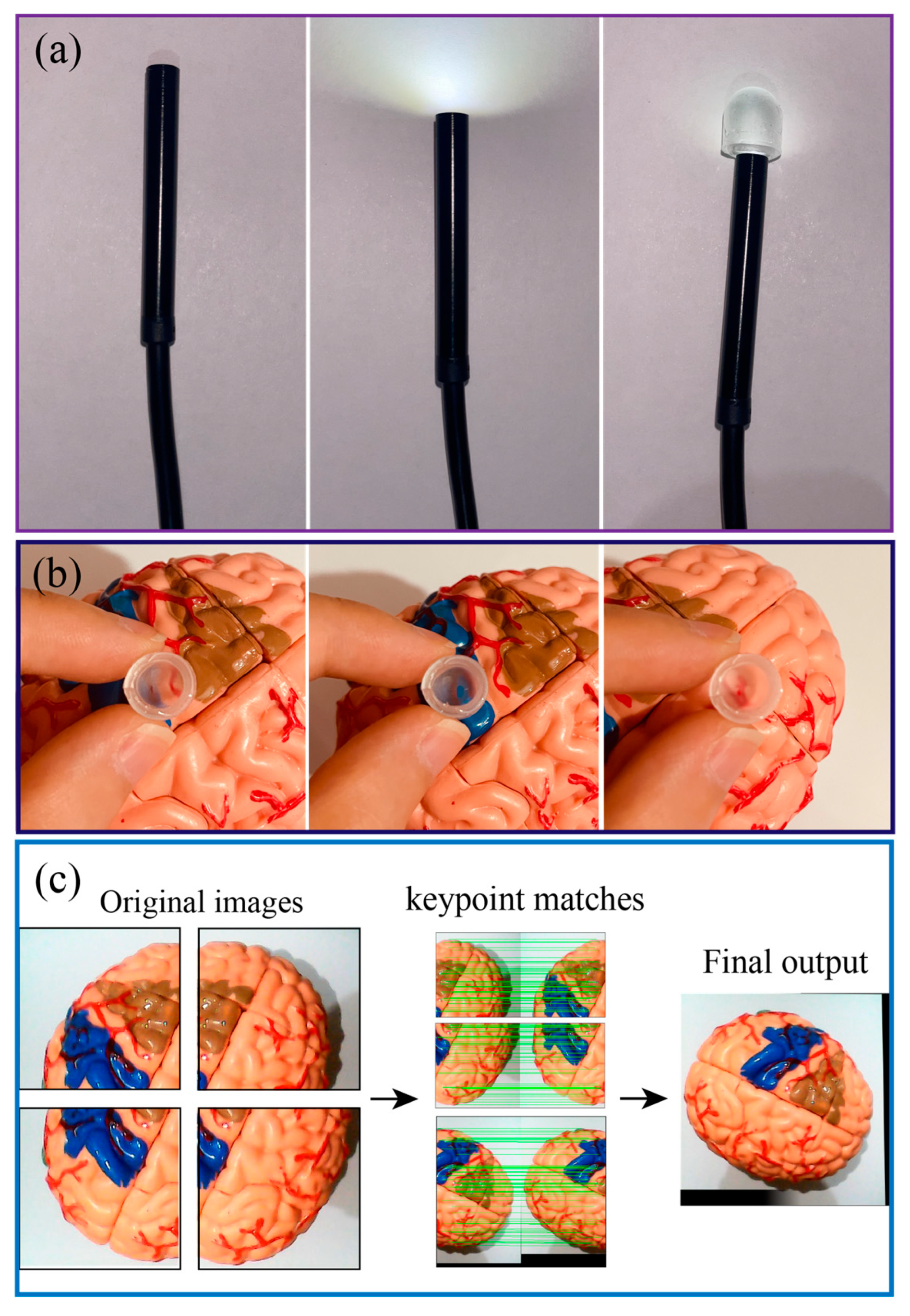
Owing to the optical transparency of PDMS, our system can retain the on-site imaging assessment capability in conventional endoscopy.
Figure 8A presents the optical transparency of the sensors when connect with an USB endoscope and a camera, clearly show that LED light can pass through the PDMS air chamber. Although, the light intensity was slightly decreased when passing through the PDMS layer, this can be further improved by smoothing the PDMS surface using a high-resolution 3D printed mold. The quality of the figure can be further improved when the sensor closely approaches the targeted tissues or organs, as shown in
Figure 8B. It is noteworthy to mention that due to the field of view of the system could be small for each single imaging capture. However, a spatial imaging resolution of organ can be obtained by scanning the robot on different locations and using the image stitching function (e.g., OpenCV's Stitcher class) as demonstrated in
Figure 8C. Overlapping the real-time processed image (enabled through the optical path of the sensor and optical fiber) with mechanical characterization data from the tactile sensor would provide meaningful information for palpation analysis.
6. Conclusions
This work develops a novel tactile sensor with mechanical flexibility and optical transparency for medical robotic control and palpation applications. The sensor was developed using a low cost and simple technique with 3D-printed mold and PDMS casting. Experimental data validate the use of this sensor for measuring the contact for between the robotic end-effector with biotissue together with differentiating tissue stiffness ranging from 0 to 2.5 MPa, suggesting a promising possibility to detect tumor through mechanical touch. We also successfully integrated the as-fabricated sensor onto a soft medical robotics driven by hydraulic soft microtubule artificial muscles. The system exhibits excellent mechanical flexibility, a high degree of freedom, along with mechanical sensing and optical visualizing capability. These features demonstrate the potential for the development of an all-in-one surgical soft robotic systems that can simultaneously perform on-site diagnosis and therapy.
Author Contributions
Conceptualization, S. Z., H.-P.P.; Methodology, S. Z., T.T.H. and C.C.N.; Software, S. Z., T.T. Hoang and C.C. Nguyen; Writing, Review, & Editing, S. Z., H.-P.P., C.C.N, H.T.T.; Supervision, H.-P.P. and T. N. Do. All authors have read and agreed to the published version of the manuscript.
Funding
H.-P.P. acknowledge the research support from the Australian Research Council (Project ID: DE200100238 and DP230101312).
Institutional Review Board Statement
“Not applicable” for studies not involving humans or animals.
Informed Consent Statement
“Not applicable.” for studies not involving humans.
Data Availability Statement
Data available on request from the authors.
Acknowledgments
This work was performed in part at the UNSW node of the Australian National Fabrication Facility, a company established under the National Collaborative Research Infrastructure Strategy to provide nano- and microfabrication facilities for Australia’s researchers.
Conflicts of Interest
The authors declare no conflict of interest.
References
- World Health, O. Cancer. World Health Organization 2022.
- Zanotelli, M.R.; Reinhart-King, C.A.J.B.i.O. Mechanical forces in tumor angiogenesis. 2018, 91–112.
- Byar, D.P.; Mostofi, F.; Cancer, V.A.C.U.R.G.J. Carcinoma of the prostate: Prognostic evaluation of certain pathologic features in 208 radical prostatectomies. Cancer 1972, 30, 5–13. [Google Scholar] [CrossRef] [PubMed]
- Barton, M.B.; Harris, R.; Fletcher, S.W.J.J. Does this patient have breast cancer?: The screening clinical breast examination: Should it be done? How? Obstet. Gynecol. Surv. 1999, 282, 1270–1280. [Google Scholar] [CrossRef] [PubMed]
- Waggoner, S.E.J.T.l. Cervical cancer. 2003, 361, 2217–2225.
- Egorov, V.; Van Raalte, H.; Sarvazyan, A.P.J.I.T.o.B.E. Vaginal tactile imaging. IEEE Trans. Biomed. Eng. 2010, 57, 1736–1744. [Google Scholar] [CrossRef] [PubMed]
- Ahn, B.; Lorenzo, E.I.S.; Rha, K.H.; Kim, H.J.; Kim, J.J.J.o.e. Robotic palpation-based mechanical property mapping for diagnosis of prostate cancer. J. Endourol. 2011, 25, 851–857. [Google Scholar] [CrossRef] [PubMed]
- Konstantinova, J.; Cotugno, G.; Dasgupta, P.; Althoefer, K.; Nanayakkara, T. Autonomous robotic palpation of soft tissue using the modulation of applied force. Proceedings of 2016 6th IEEE International Conference on Biomedical Robotics and Biomechatronics (BioRob); pp. 323–328.
- Ahn, B.; Kim, Y.; Oh, C.K.; Kim, J. Robotic palpation and mechanical property characterization for abnormal tissue localization. Med. Biol. Eng. Comput. 2012, 50, 961–971. [Google Scholar] [CrossRef] [PubMed]
- Beccani, M.; Di Natali, C.; Benjamin, C.E.; Bell, C.S.; Hall, N.E.; Valdastri, P.J.S.; Physical, A.A. Wireless tissue palpation: Head characterization to improve tumor detection in soft tissue. Sensors Actuators A Phys. 2015, 223, 180–190. [Google Scholar] [CrossRef]
- Csavina, J.; Field, J.; Félix, O.; Corral-Avitia, A.Y.; Sáez, A.E.; Betterton, E.A. Effect of wind speed and relative humidity on atmospheric dust concentrations in semi-arid climates. Sci. Total. Environ. 2014, 487, 82–90. [Google Scholar] [CrossRef] [PubMed]
- Beccani, M.; Di Natali, C.; Sliker, L.J.; Schoen, J.A.; Rentschler, M.E.; Valdastri, P.J. Wireless tissue palpation for intraoperative detection of lumps in the soft tissue. IEEE Trans. Biomed. Eng. 2013, 61, 353–361. [Google Scholar] [CrossRef]
- Trejos, A.L.; Jayender, J.; Perri, M.T.; Naish, M.D.; Patel, R.V.; Malthaner, R.A. Experimental evaluation of robot-assisted tactile sensing for minimally invasive surgery. In Proceedings of the 2008 2nd IEEE RAS & EMBS International Conference on Biomedical Robotics and Biomechatronics; pp. 971–976.
- Wanninayake, I.B.; Seneviratne, L.D.; Althoefer, K. Novel indentation depth measuring system for stiffness characterization in soft tissue palpation. In Proceedings of the 2012 IEEE International Conference on Robotics and Automation; pp. 4648–4653.
- McKinley, S.; Garg, A.; Sen, S.; Kapadia, R.; Murali, A.; Nichols, K.; Lim, S.; Patil, S.; Abbeel, P.; Okamura, A.M. A single-use haptic palpation probe for locating subcutaneous blood vessels in robot-assisted minimally invasive surgery. In Proceedings of the 2015 IEEE International Conference on Automation Science and Engineering (CASE); pp. 1151–1158.
- Li, M.; Luo, S.; Nanayakkara, T.; Seneviratne, L.D.; Dasgupta, P.; Althoefer, K.J.S.; Physical, A.A. Multi-fingered haptic palpation using pneumatic feedback actuators. Sensors Actuators A Phys. 2014, 218, 132–141. [Google Scholar] [CrossRef]
- Scanlan, P.; Hammer, S.; Good, D.; Phipps, S.; Stewart, G.; McNeill, S.; Shu, W.; Reuben, R.J.S.; Physical, A.A. Development of a novel actuator for the dynamic palpation of soft tissue for use in the assessment of prostate tissue quality. Sensors Actuators A Phys. 2015, 232, 310–318. [Google Scholar] [CrossRef]
- Herzig, N.; Maiolino, P.; Iida, F.; Nanayakkara, T.J.I.R.; Letters, A. A variable stiffness robotic probe for soft tissue palpation. IEEE Robot. Autom. Lett. 2018, 3, 1168–1175. [Google Scholar] [CrossRef]
- Sornkarn, N.; Nanayakkara, T.J. Can a soft robotic probe use stiffness control like a human finger to improve efficacy of haptic perception? 2016, 10, 183–195.
- Naidu, A.S.; Escoto, A.; Fahmy, O.; Patel, R.V.; Naish, M.D. An autoclavable wireless palpation instrument for minimally invasive surgery. In Proceedings of the 2016 38th Annual International Conference of the IEEE Engineering in Medicine and Biology Society (EMBC); pp. 6489–6492.
- Nagatomo, T.; Miki, N.J.M.; Letters, N. Three-axis capacitive force sensor with liquid metal electrodes for endoscopic palpation. Micro Nano Lett. 2017, 12, 564–568. [Google Scholar] [CrossRef]
- Quang-Khang, P.; Minh-Dung, N.; Binh-Khiem, N.; Phan, H.-P.; Matsumoto, K.; Shimoyama, I. Multi-axis force sensor with dynamic range up to ultrasonic. In Proceedings of the 2014 IEEE 27th International Conference on Micro Electro Mechanical Systems (MEMS); pp. 769–772.
- Faragasso, A.; Bimbo, J.; Stilli, A.; Wurdemann, H.A.; Althoefer, K.; Asama, H.J.S. Real-time vision-based stiffness mapping. Sensors 2018, 18, 1347. [Google Scholar] [CrossRef]
- Peng, P.; Sezen, A.; Rajamani, R.; Erdman, A.J.S.; physical, A.A. Novel MEMS stiffness sensor for force and elasticity measurements. Sensors Actuators A Phys. 2010, 158, 10–17. [Google Scholar] [CrossRef]
- Naish, M.D.; Patel, R.V.; Trejos, A.L.; Perri, M.T.; Malthaner, R.A.J.S.R.S.A. Visions. Robotic techniques for minimally invasive tumor localization. 2011, 469–496.
- Gent, A.N.J.R.C. Technology. On the relation between indentation hardness and Young's modulus. 1958, 31, 896–906.
- Thai, M.T.; Phan, P.T.; Tran, H.A.; Nguyen, C.C.; Hoang, T.T.; Davies, J.; Rnjak-Kovacina, J.; Phan, H.P.; Lovell, N.H.; Do, T.N.J.A.S. Advanced Soft Robotic System for In Situ 3D Bioprinting and Endoscopic Surgery. Adv. Sci. 2023, 2205656. [Google Scholar] [CrossRef]
|
Disclaimer/Publisher’s Note: The statements, opinions and data contained in all publications are solely those of the individual author(s) and contributor(s) and not of MDPI and/or the editor(s). MDPI and/or the editor(s) disclaim responsibility for any injury to people or property resulting from any ideas, methods, instructions or products referred to in the content. |
© 2023 by the authors. Licensee MDPI, Basel, Switzerland. This article is an open access article distributed under the terms and conditions of the Creative Commons Attribution (CC BY) license (http://creativecommons.org/licenses/by/4.0/).
