One of the solutions for reducing the time allocated to the programming of the numerical control while respecting the safety of the program and the correctness of the trajectories generation sequences from the relative movement of the tool-piece is offered by the numerical control system CNC-plus, of the German company
R & S KELLER GmbH, system implemented by one of the most important manufacturers of CNC machine tools, the multinational company
HAAS Automation Inc. see [
12,
13,
14,
15,
16,
17]. This is based on the existence of predefined subroutines specific to each type of common surface existing on the part and their automatic allocation with the selection of the respective surface type from the "program's surface portfolio". Thus, the programmer is no longer obliged to write the entire kinematic description program of the piece, but only the elements that cannot be defined by subroutines and, OF course, the connecting elements between the predefined cycles.
Practically, for the repetitive elements that would have required the conception of sequences of C.N. repetitive in form but with different geometric addresses, consuming programming time, specific predefined subroutines are created. In this way, the programming activity is greatly simplified, especially in the most resource-consuming part - that of the geometric description of the tool-part trajectory.
2.1. Predefined cycles for drilling: G81
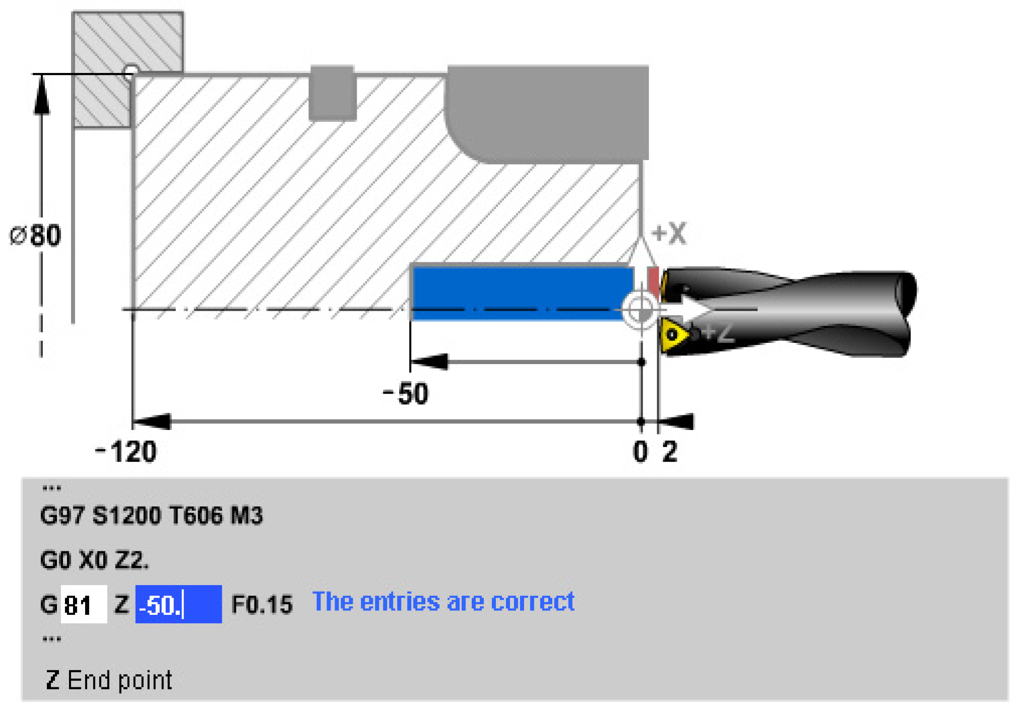
In
Figure 1, the simplest subroutine is analyzed - common for other processings as well - namely, the drilling subroutine, which has the preparatory function code:
G81. We say that this subroutine is also common for other processing because it contains the same movements - to be described in the program - as for other processing of the holes, such as: widening, deepening, laming and reaming, what differs is the processing regime and of course the type of tool.
In the first line, the A.P. speed is set. -at the value of 1200 rpm, i.e. S1200, specify the number of the tool with which the T6 processing is done -tool no. 6- and its length correction -code 06 which is added after the tool number-. Also in the first line, the direction of rotation of A.P. is specified. through the auxiliary function M, where the direction of rotation CLW is indicated by the code M3 - the direction of rotation of the clock hands.
In the second line, the tool moves to the cycle start position, a position located coaxially with the AAP (x=0) and at a safety distance of 2 mm from the part z=2: rapid movement (G0), up to the coordinate point x=0 mm and z=2 mm. It is noted that the OZ axis is the main shaft axis (AAP), and the OX axis is the axis in the radial direction. Dimensions will be given, where appropriate, on OX, on diameter, not on radius.
The third line is actually the one that calls the drilling subroutine and, it is observed that the number of data to be entered is minimal, because the subroutine itself has a simple kinematics; upon reading the G81 code, the numerical control equipment will start the drilling cycle: the rotation movement of the main shaft is started in the indicated direction, the advance is switched to the indicated value - through the function: F0.15 - and the drilling is performed along the length of the part until it is reached dimension z = -50 mm from the drawing, followed by the rapid withdrawal of the tool to the cycle start position.
2.2. Predefined cycles for channel turning: G75.
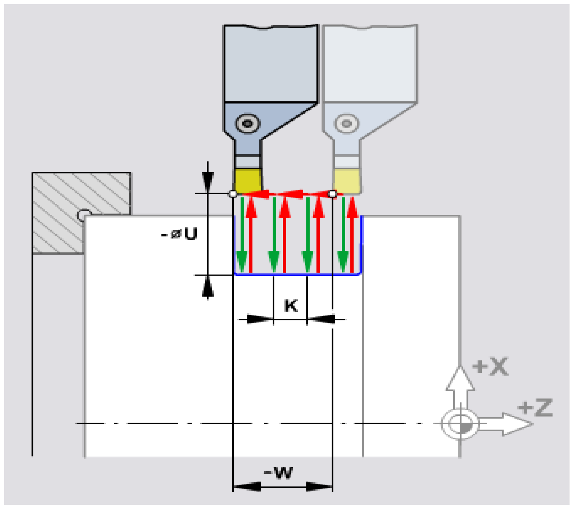
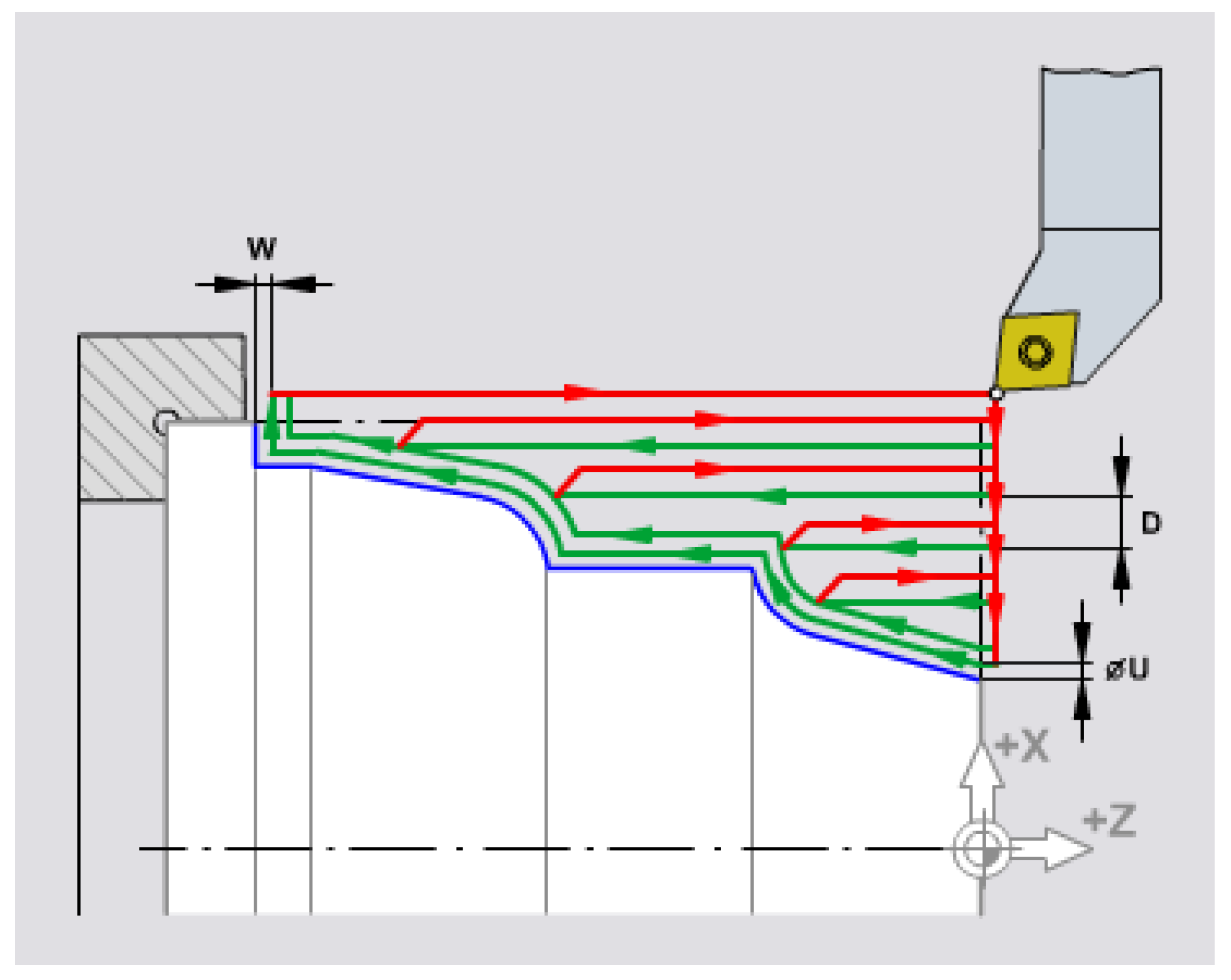
It is a subroutine that saves many intermediate phrases, especially when processing channels where the width of the knife is much lower than the channel width. In
Figure 2 shows the intermediate sequences necessary to create the channels according to the elevations in the execution drawings.
The repetitive circuits that the tool must describe are observed:
-penetration into the part with a transverse advance over a distance given by the U... ;
-quick withdrawal to the initial quota,
-lateral movement by the distance K... (a distance that is chosen approximately 5/6 of the width of the knife, in the case below 1.5 mm;
-resume: repeating the cycle until reaching the dimension W..., dimension which is actually equal to the width of the channel-width of the knife/tool: 10 - 1.8 mm.
Under these conditions, for a concrete case of processing [
12], the subroutine is presented as in
Figure 3. It can be seen that, just like in the drilling subroutine, the first phrase in the program ensures the initial setting of the A.P. speed ( here n =120 rpm, so
S120), specifies the tool (
T4 ) and its correction (
04) as and the direction of rotation of AP, which here is CCLW, i.e. counter-clockwise (
M4).
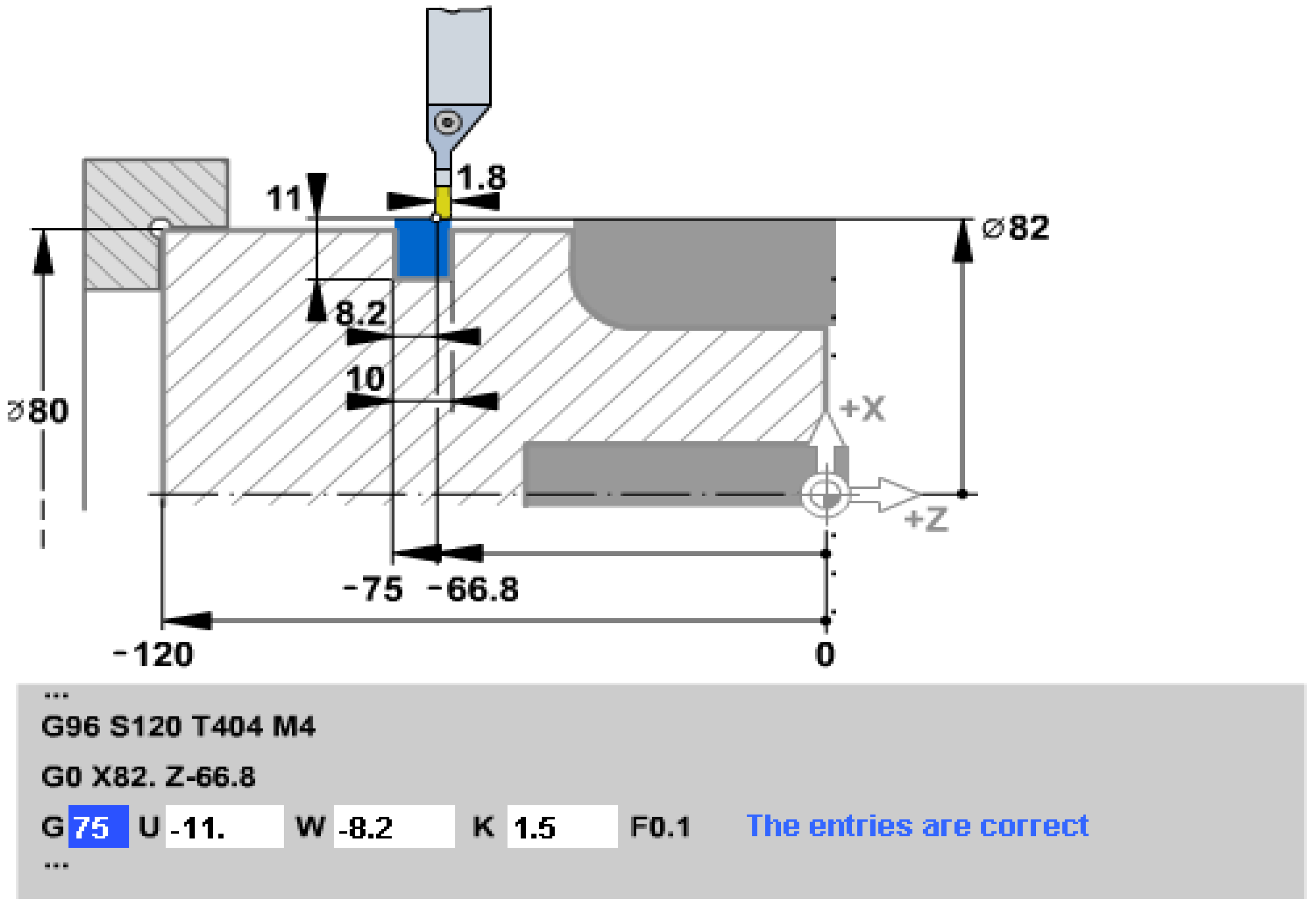
The second phrase ensures positioning with rapid advance ( G0 ) at the cycle start point ( x=82 z=68.8 )
The third phrase - from
Figure 3 - the figure extracted from the interactive preparation software [
12], is the one that defines the subroutine proper for turning the channels:
G75; the elements that intervene in the phrase are as in
Figure 2, i.e. the value 8.2 mm from address
W represents the width of the channel from which the width of the tool edge is subtracted, at address
U the penetration depth + initial distance etc. is given, and the working advance is 0.1 mm/rot
(F0.1)
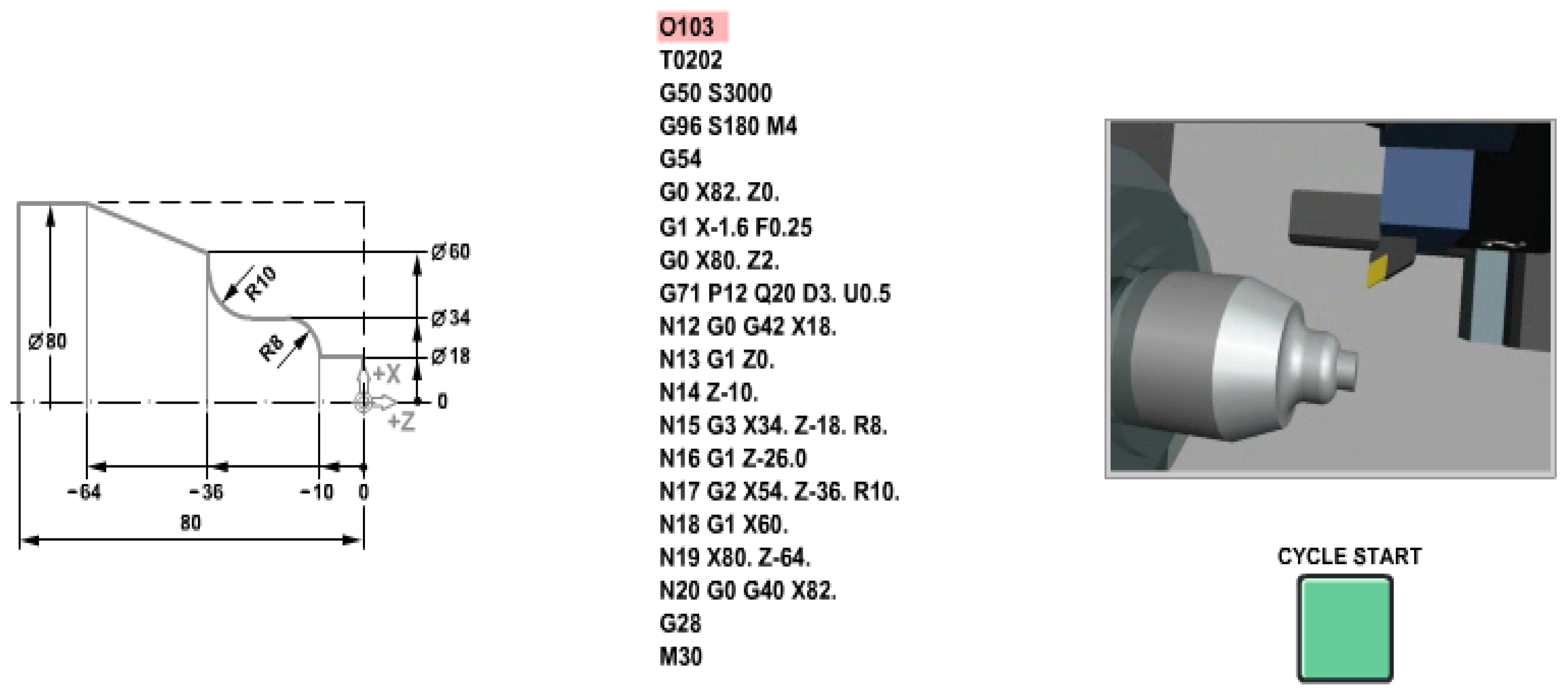
2.3. Predefined cycles for turning complex/compound profiles: G71.
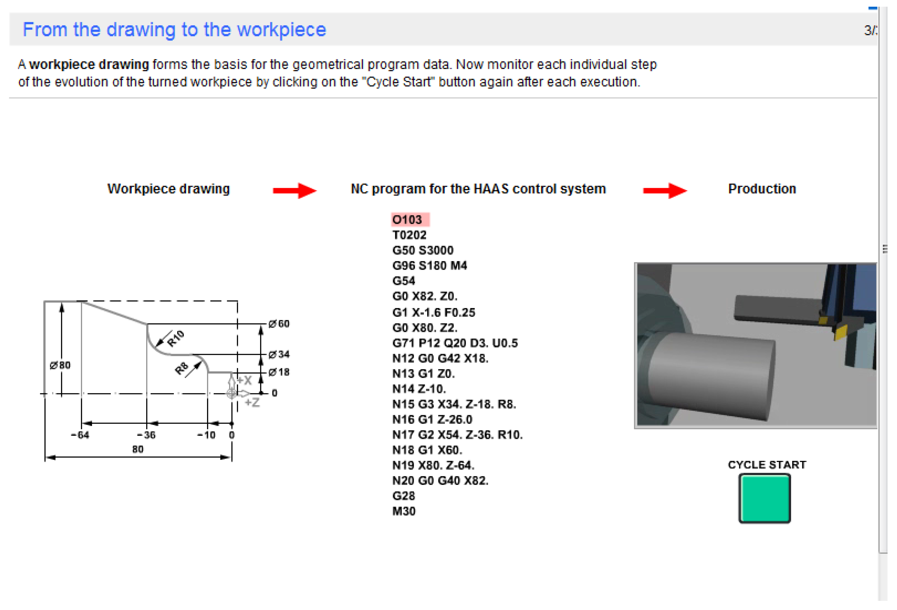
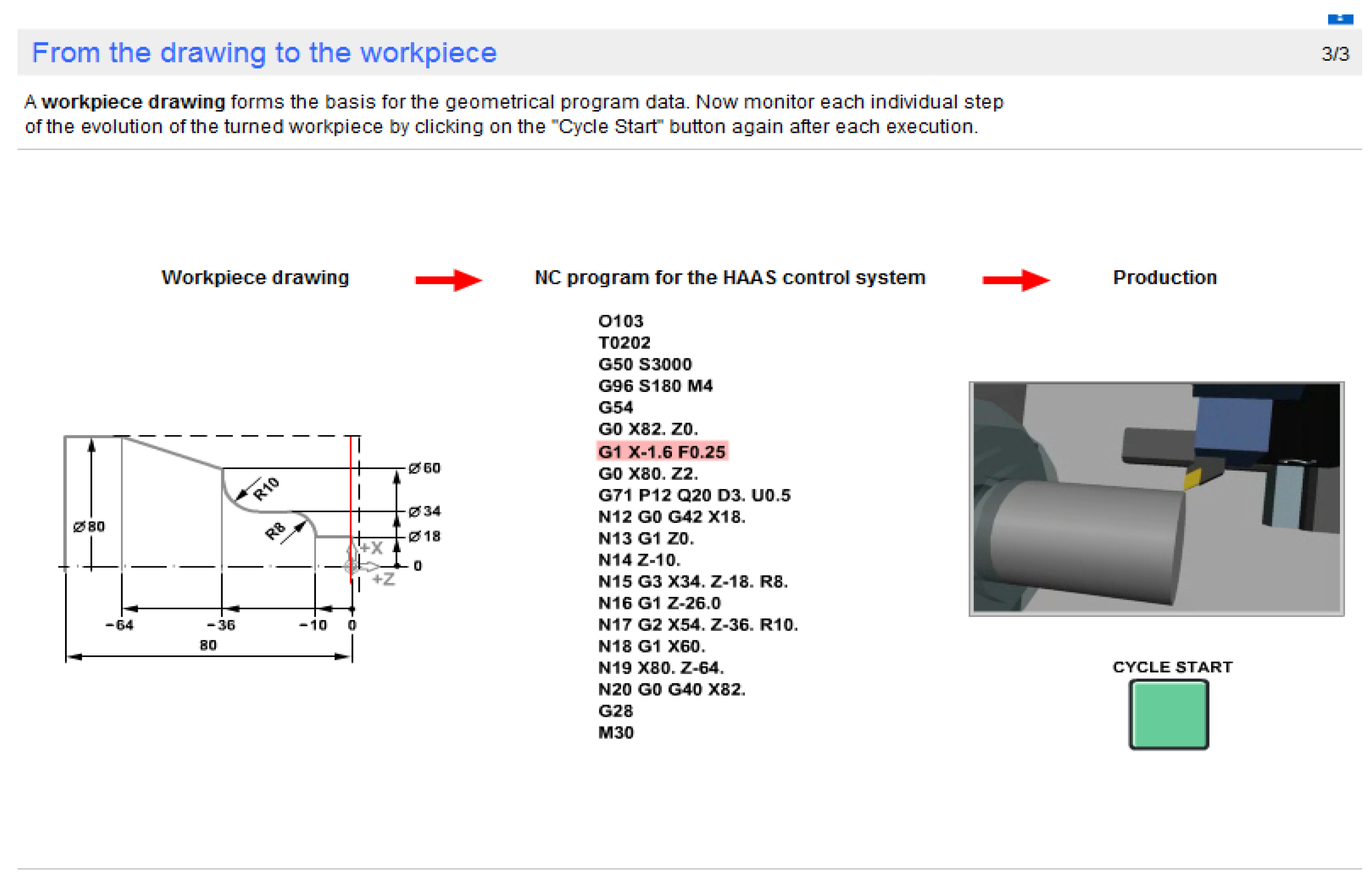
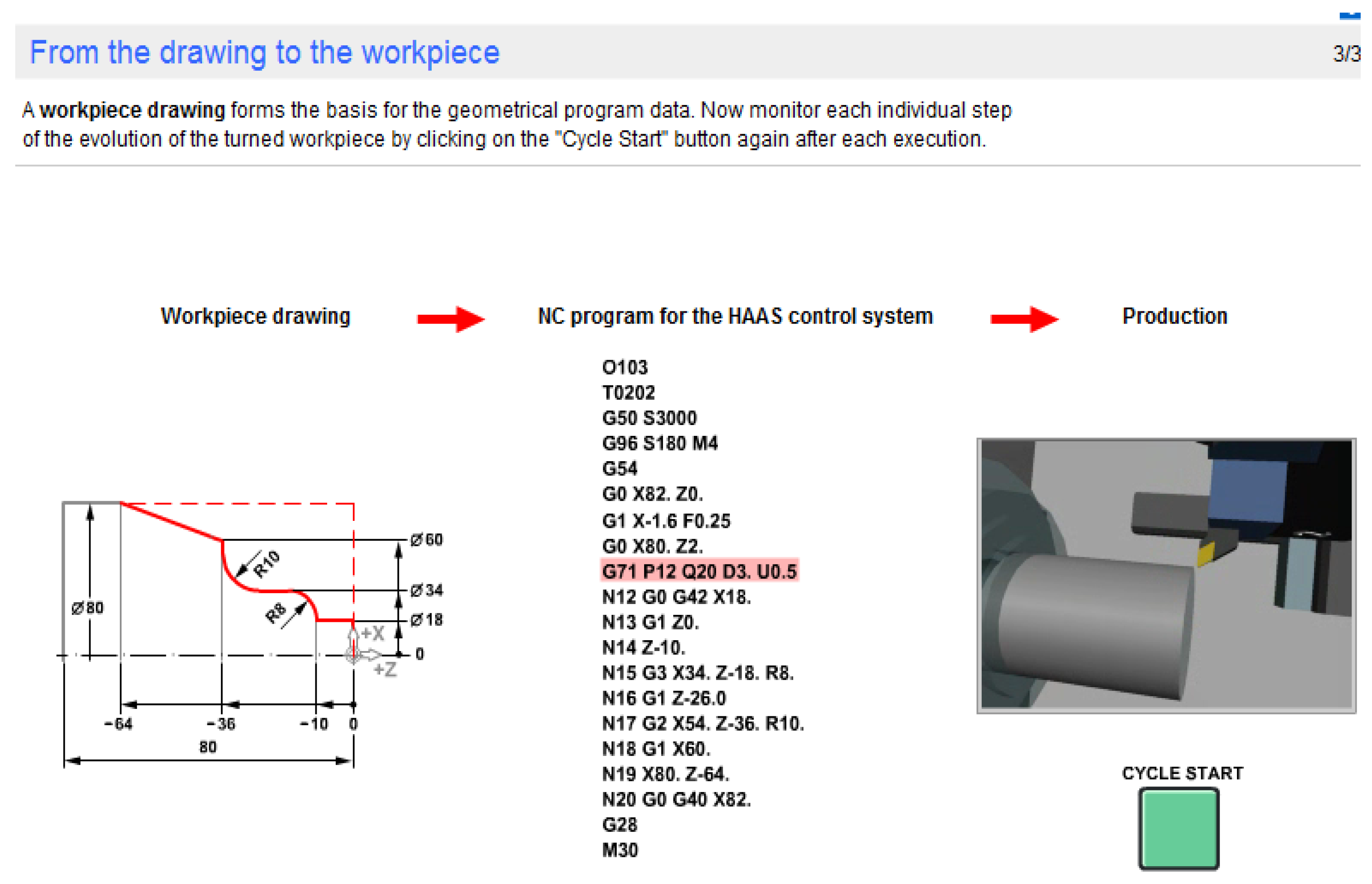
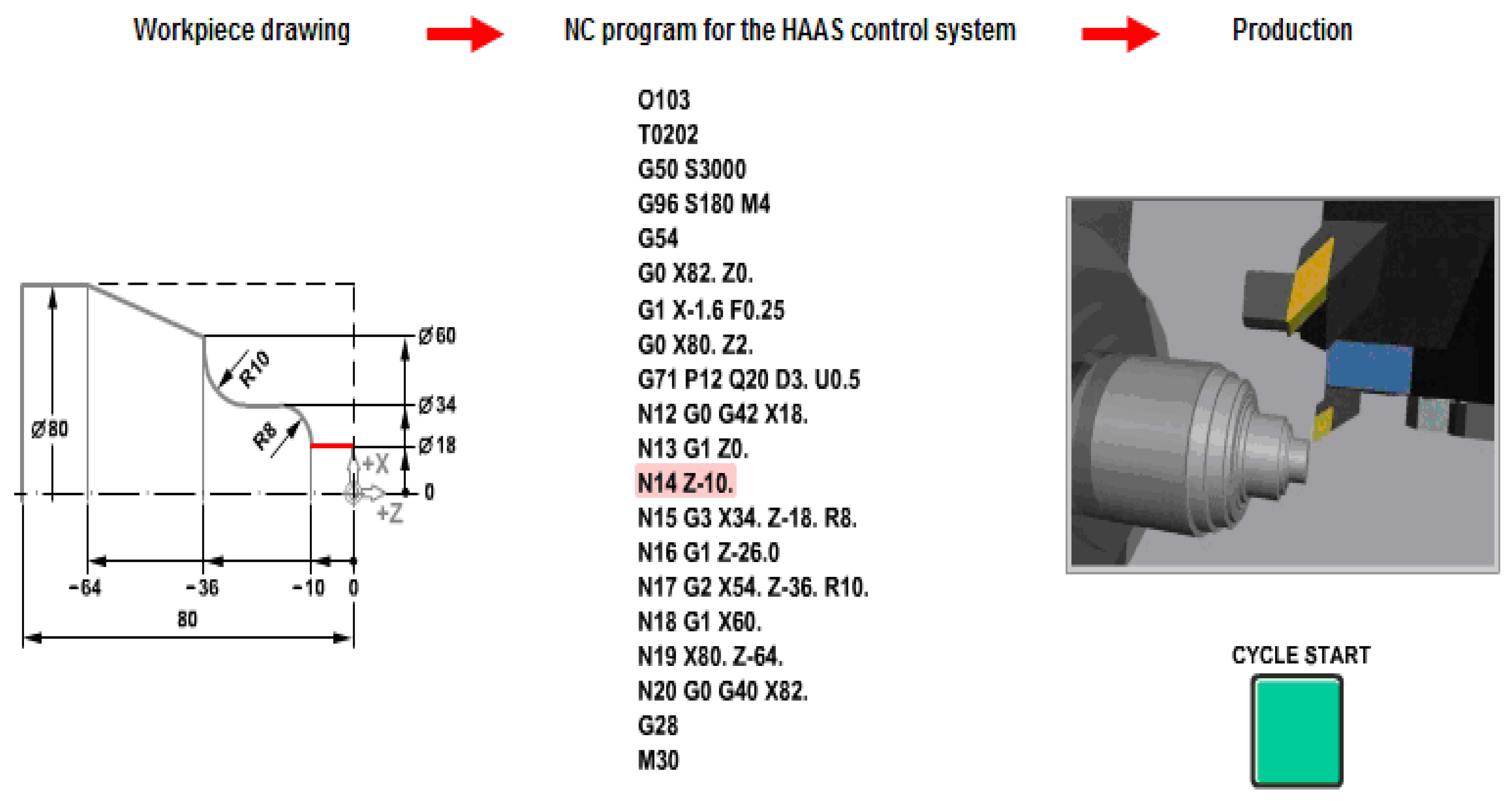
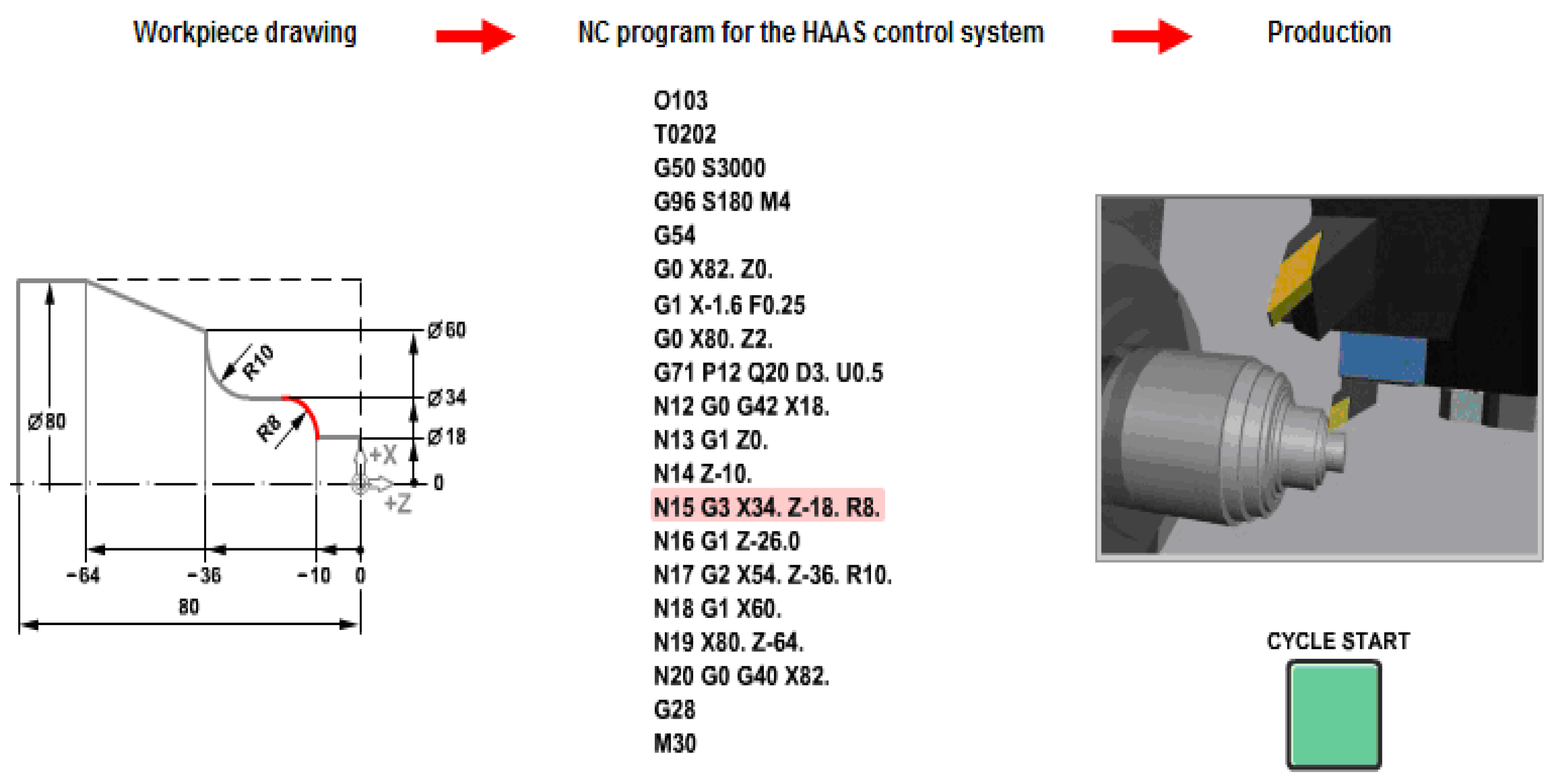
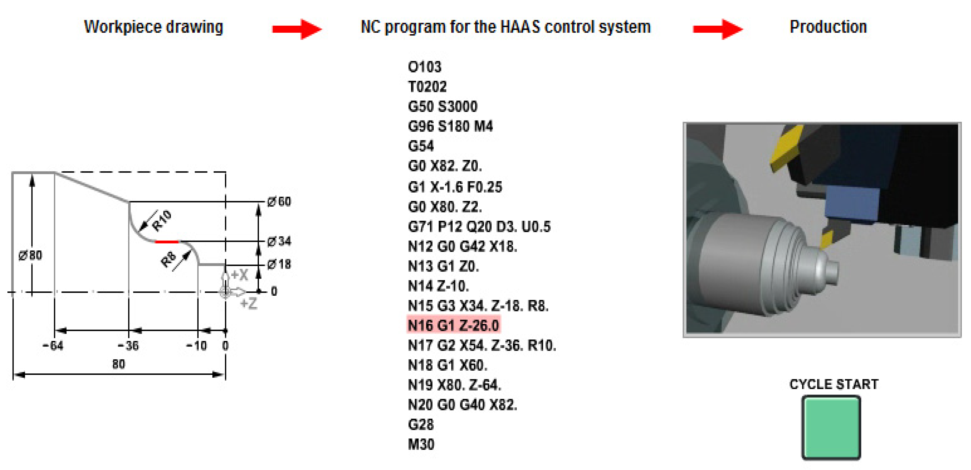
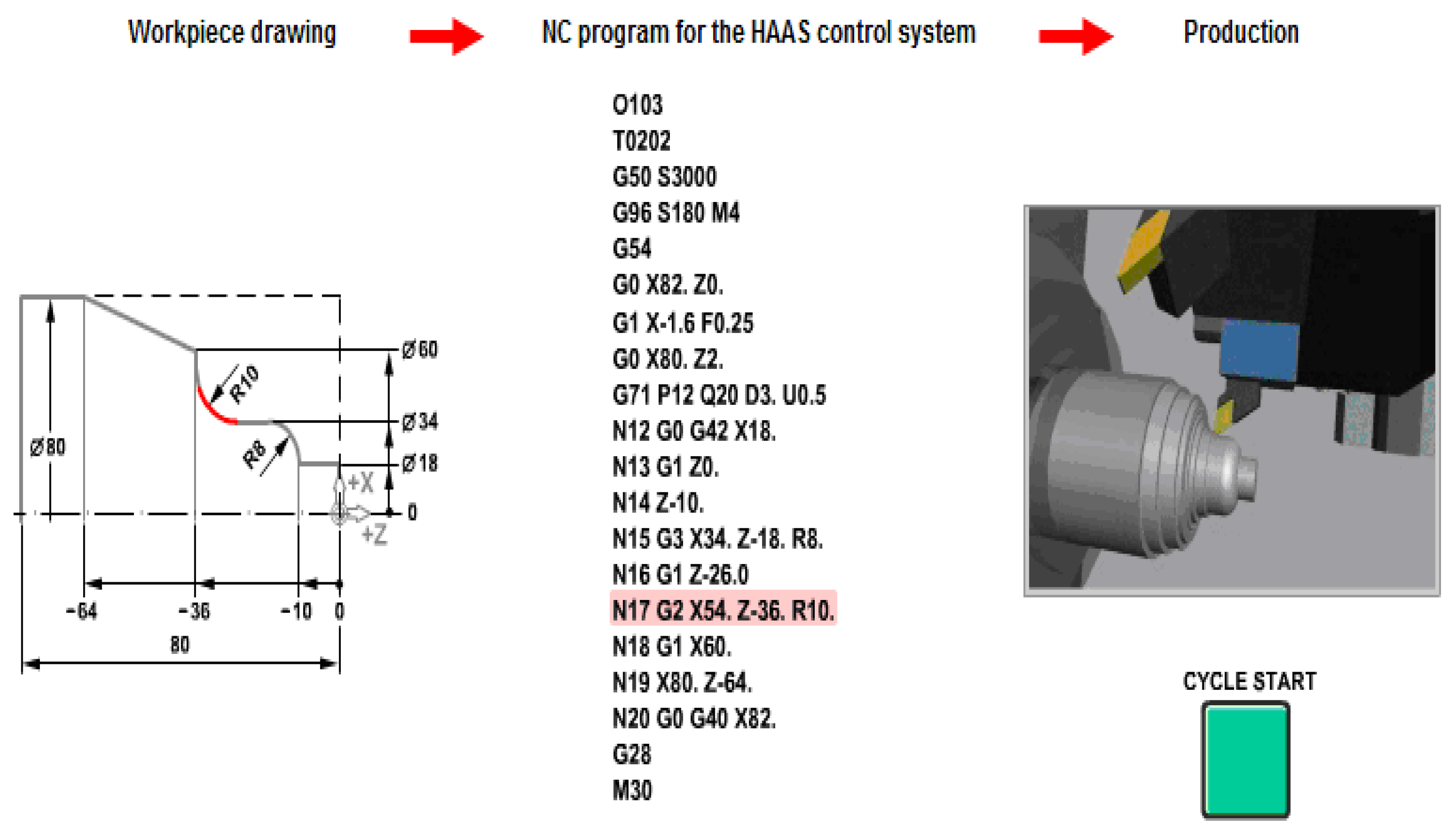
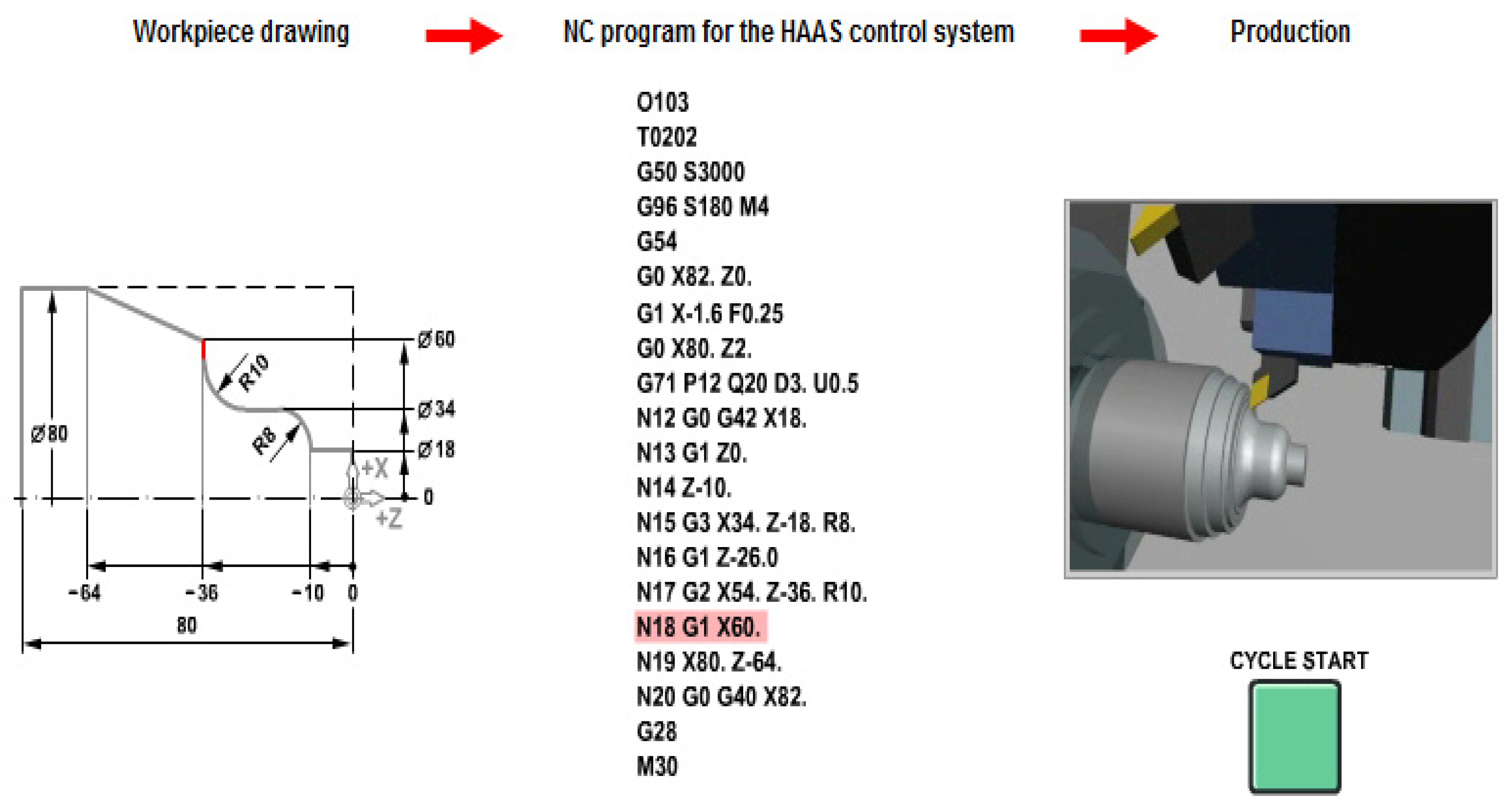
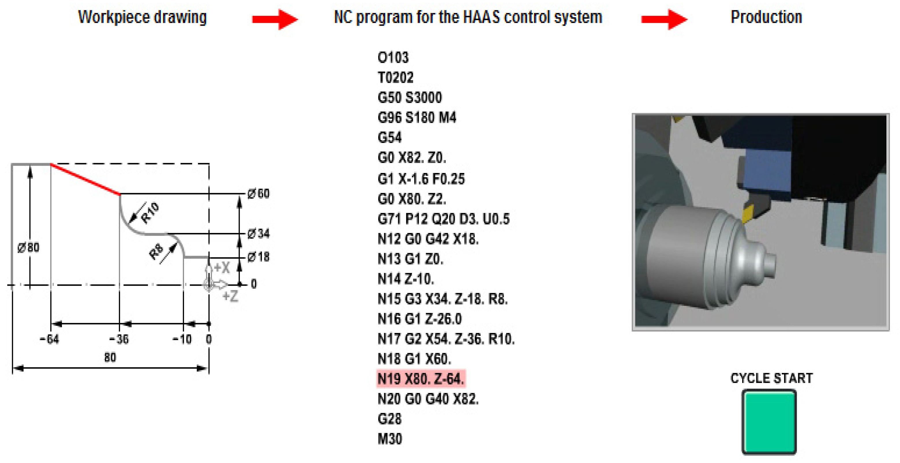
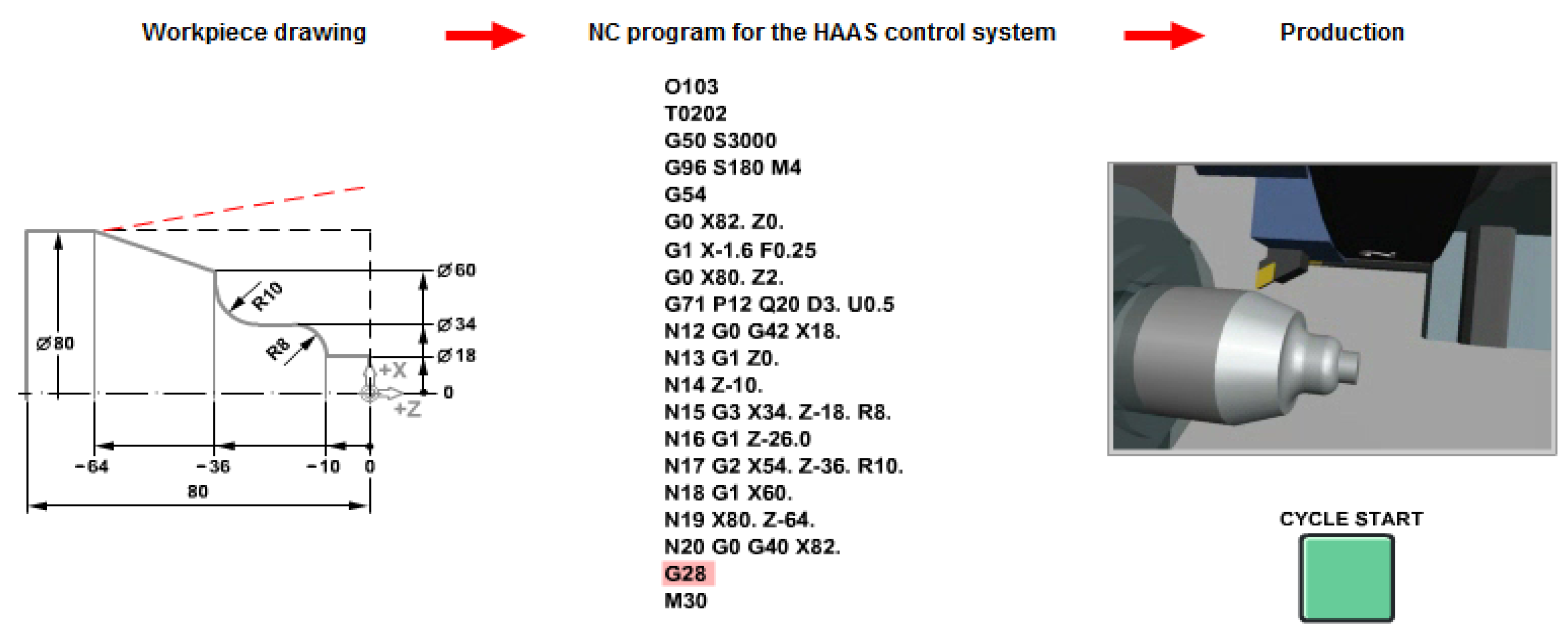
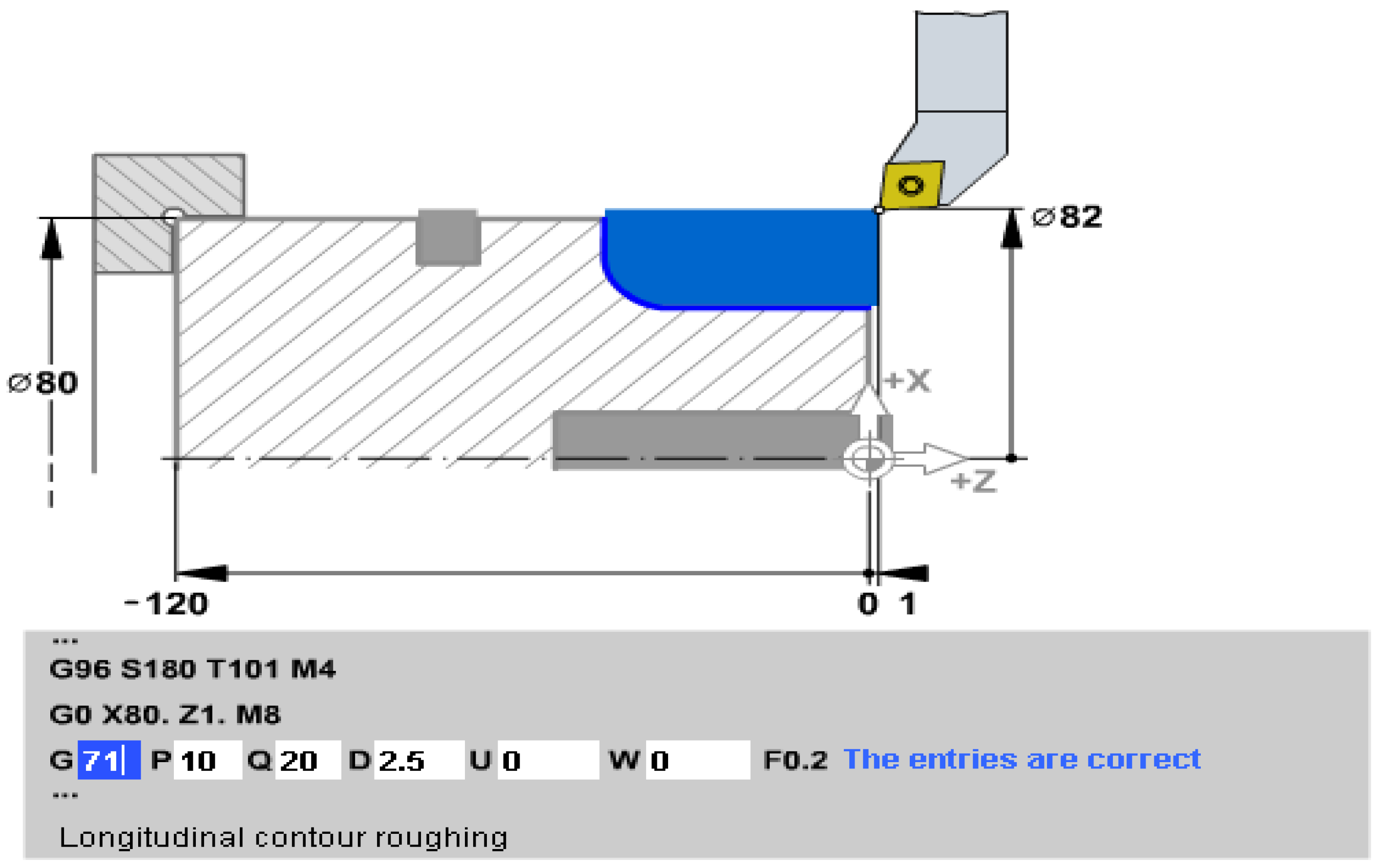
This subroutine is in fact the most important from the point of view of frequency of appearance, especially through the substantial effect of simplifying the program. This effect and the way the subroutine works also results from
Figure 4, see [
12,
14].
Practically, it is known that, when processing complex surfaces, before reaching the contour generation of the surface, several intermediate circuits must be made to remove the processing addition. The number of these closed circuits - pictured next to it - is the larger the volume of material to be removed or the jump in diameters.
From the point of view of programming, this fact represents an important inconvenience because it leads to a large consumption of time and resources - on the one hand, the final outline is calculated, the mandatory stage anyway - but, on the other hand, time is also consumed for the calculation independent of each circuit and making the appropriate program sequence for them.
The advantage of using the complex profile turning subroutine results from the fact that, in the case of its use, only the final contour is programmed and only the following technological elements are specified:
- the processing additions that we want to reserve before the final pass (radial addition U... and frontal W...)
- the cutting depth of each pass (given by D...)
- The number of the address where the definition of the contour starts and where it ends, i.e. P ... and respectively Q ...
In
Figure 5 shows the turning subroutine of complex profiles; as in the previous cases, in the first two sequences (phrases) of the program, the initial setting of the machine is made. In the present case, a speed of 180 rpm will be used. for AP (
S180 ), tool
T1 will be used, and the direction of rotation is CCLW given by auxiliary function
M4.
The starting point is also defined here (at X80 and Z1 mm) and the cooling liquid is additionally started, through the M8 command, considering that a more intensive processing is to be performed. Its stopping will be done at the end of the processing through an M9 cancellation command which is not found here, but will have to be added later by the programmer, somewhere in the program content.
It can therefore be observed that, instead of entering into the program several phrases calculated separately for each circuit, a single one is entered, the one defining this subroutine, but which includes the reference elements: G71 is the code of the subroutine.
A detail of the application of these processing cycles is presented in subchapter xxx4
2.4. Definition of some common types of predefined cycles for milling processing
In the following, an interactive auxiliary method for training numerical control programmers is presented, which has proven its effectiveness in practice, applicable to milling processes. The advantage of using the method consists in the fact that the learner-programmer has the opportunity to analyze the "putting into the phrase" and then into the program the addresses and the various commands necessary for processing on numerical control machine tools, respecting the sequence accepted by the processing system and with highlighting the meaning of each "phrase" and the addresses of the "words" in it.
Also, the student-programmer has the opportunity to see the composition of the primary initialization phrases of the machine-tool as well as the final ones for resetting and bringing the MUCN to its initial state, as well as the facilities resulting from the use of the concept of "commented programs".
The concept involves making the connection between the content of the "phrase" from the point of view of writing and its meaning from the technological point of view, or, in other words, the connection between the syntax of the phrase and its semantics.
In practice, the Numerical Command program related to a certain processing for a part will be written, with all the necessary phrases and then the content of each will be described. phrases.
2.4.1. The C.N program for blade processing - circular pockets.
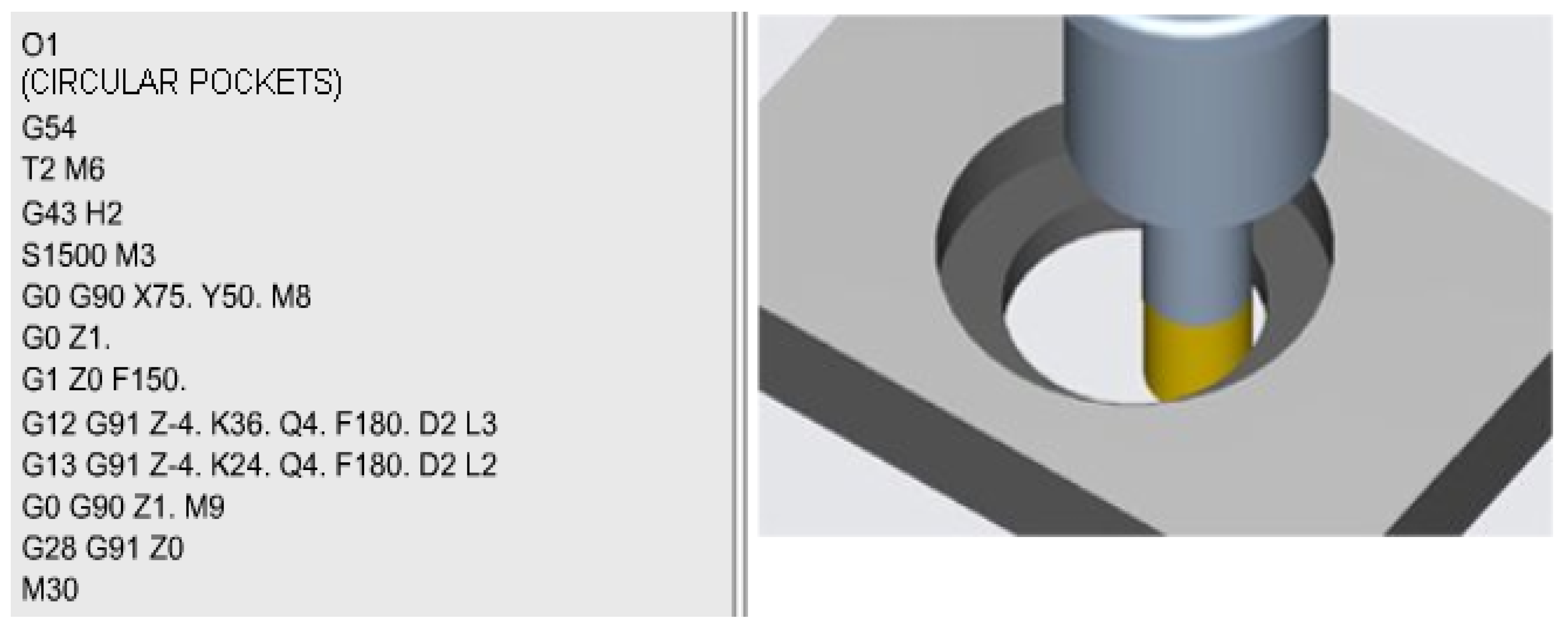
The content of the commented program in
Figure 6 is as follows (in order not to introduce interpretation errors, the comments are made in the order of the addresses in the phrase):
O1 – name of the program/file
G54 – initialization, origin transfer from the origin of the machine-tool to the origin of the part (chosen here in the lower left corner). The operation is accompanied by the physical positioning by direct command of the mobile organ (cutting tool) at the point corresponding to the new origin. In this way, at the G54 command, the coordinates of this point are assigned and interpreted as the new origin (in this case the origin of the part)
T2 M6 – tool change, tool no. 2 from the tool shop is assigned
G43 H2 – tool length correction
S1500 M3 – A.P. rotation with 1500 rpm and direction of rotation CLW
G0 G90 X75. Y50. M8 – the movement of the tool with rapid advance, in absolute coordinates at the point X75 Y50 (the center of the bore) with the start of the cooling liquid (the auxiliary functions M are passed at the end of the phrase.
G0 Z1. – moving the tool with rapid feed in the coordinate point Z1. (practically, the tool descends vertically, along the OZ axis, up to 1 mm from the part). It is mentioned that the movement from the previous sequence was done with the tool retracted vertically at the point of maximum amplitude.
G1 Z0 F150 - movement with working feed until contact with the part (Z0) and the feed speed used is 150 mm/min.
G12 G91 Z-4. K36. Q4. F180. D2 L3 – subroutine for processing the blade (circular pocket). The relative coordinates are used (given by the preparatory function G91); the first processing plane has coordinates located 4 mm below the zero level, the processing radius is 36 mm. The penetration in the radial direction at each described circle is 4mm. Advance speed 180 mm/min. The D2 tool correction is assigned to the diameter and is assigned to the T2 tool and in total the cycle will be repeated 3 times. This means that at the end the lamaje will be 12 mm deep.
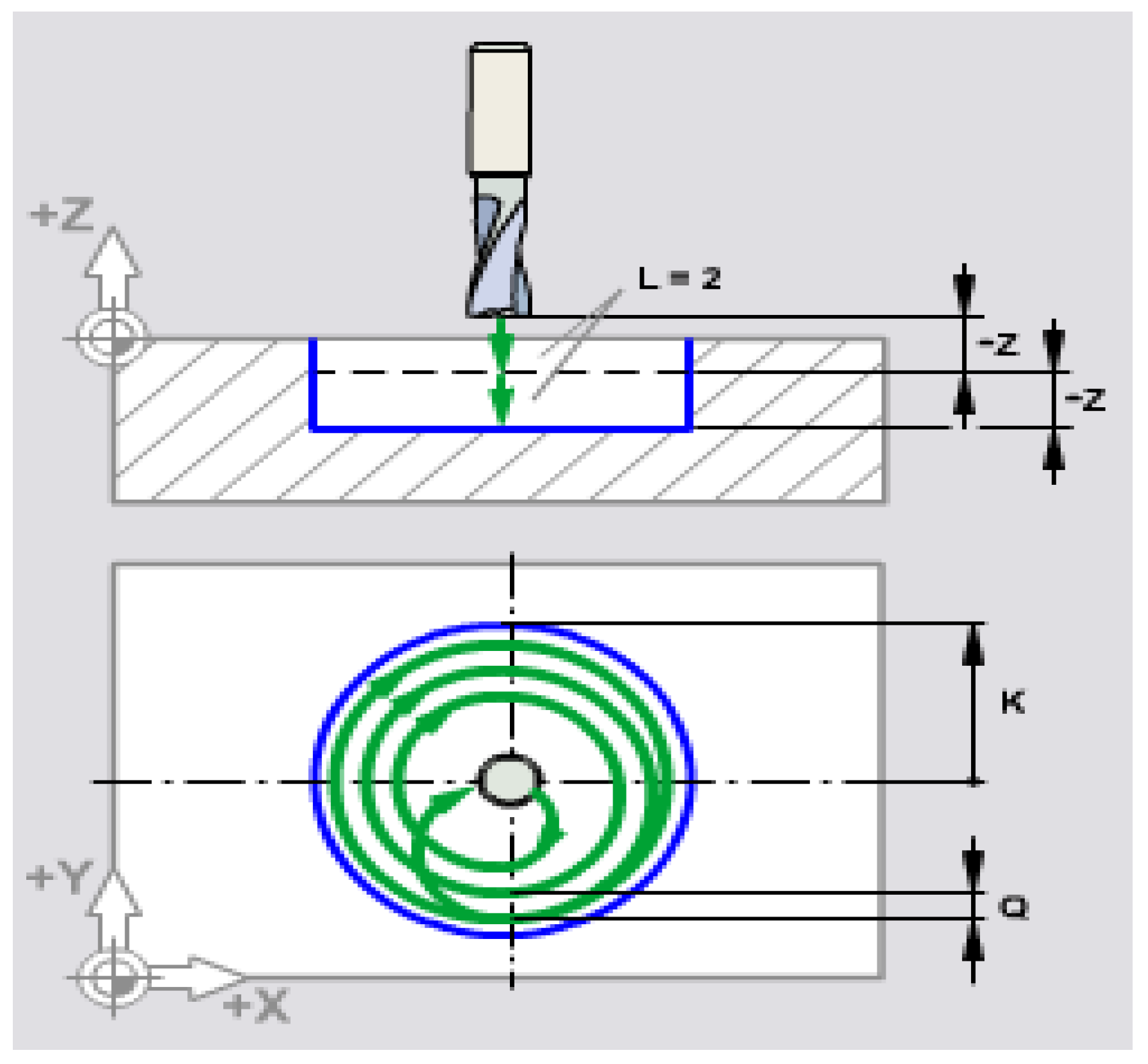
The meaning of the addresses in the phrase also results from
Figure 7. It is valid for both subroutine
G12 and
G13.
Both are subroutines for machining bores (lamination, machining circular pockets, etc.), the first by describing the machining circuit clockwise ( CLW ) and the second counterclockwise ( CCLW ).
The figure shows the meaning of addresses Z... K... Q... and respectively L...
The commented program continues with subroutine G13 whose meaning is similar to that of G12 above, and with the phrases:
G0 G90 Z1. M9 – rapid feed movement, in absolute coordinates up to the height of 1 mm above the part and stopping the coolant.
G28 G91 Z0 – specific Keller – Haas sequence, for resetting and bringing the tool to coordinates relative to the machine zero point.
M30 - end of program.
2.4.2. The CNC program for machining flange holes (circular pattern) and hole networks (linear pattern).
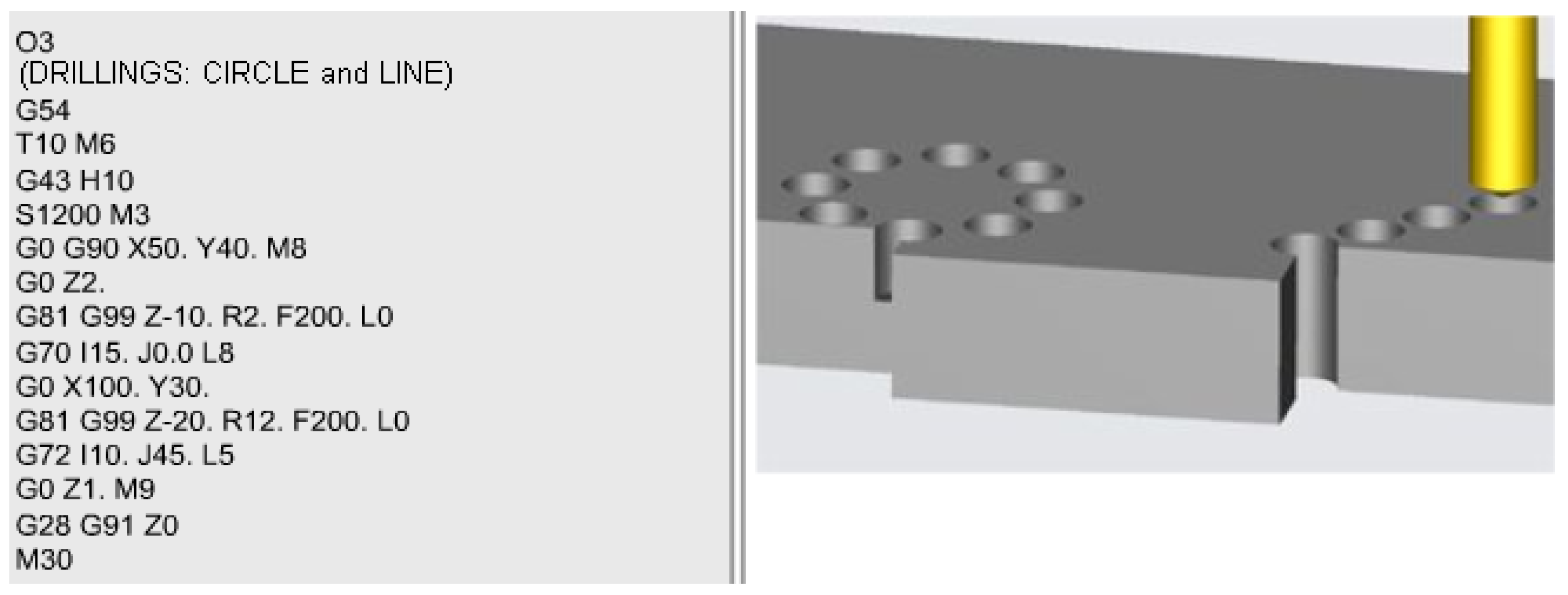
The content of the program and the processing scheme is given in
Figure 8.
As in the previous case, (the starting sequences are similar because they assume the standard initialization steps):
O3 – name of the program / file
G54 – initialization, origin transfer from the origin of the machine-tool to the origin of the part (also chosen here in the lower left corner).
T10 M6 – tool change, tool no. 10 from the tool shop is assigned
G43 H10 – tool length correction
S1200 M3 – A.P. rotation with 1200 rpm and the direction of rotation to the right, CLW
G0 G90 X50. Y40. M8 – moving the tool with rapid advance, in absolute coordinates at the point X50 Y40 (the center of the flange) with the start of the cooling liquid
G0 Z2. – moving the tool with rapid feed in the Z2 coordinate point. (practically, the tool descends vertically, along the OZ axis, up to 2 mm from the part).
G81 G99 Z-10. R2. F200. L0 – standard hole machining subroutine ( G81 ) with machining to a depth of 10 mm ( Z-10 ) and with retraction of the tool relative to a reference plane ( G99 ) which is located at the reference distance of 2 mm above the part (R2). The processing is programmed to be done with a feed speed of 200 mm/min, but it will not start in this phrase (L0) but in the next one that will describe the template (circular pattern) on which the holes will be distributed as well as the number of repetitions/drilling successive.
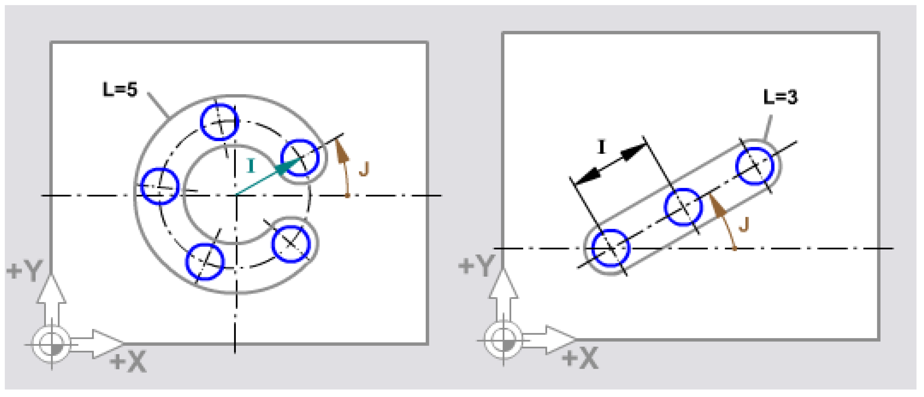
G70 I15. J0. L8 - flange hole processing subroutine. The radius of the dividing circle is 15 mm ( I15 ) and the first hole starts from an angle to the center of zero degrees ( J0.). The number of repetitions, i.e. of flange holes, is eight ( L8 )
Obs. The description of the processing scheme for the circular pattern (flange holes) can be found in
Figure 9a.
G0 X100. Y30. – fast forward movement to the coordinate point (X100,Y 30) which is actually the center of the first hole in the linear hole network (linear pattern)
G81 G99 Z-20. R12. F200. L0 – standard hole machining subroutine ( G81 ) with machining to a depth of 20 mm ( Z-20 ) and with retraction of the tool relative to a reference plane ( G99 ) which is located at the reference distance of 12 mm above the part ( R12 ). The processing is programmed to be done with a feed speed of 200 mm/min, but it will not start in this phrase ( L0 ) but in the next one that will describe the template (linear pattern) on which the holes will be distributed as well as the number of successive repetitions.
G72 I10. J45. R5 – subroutine for processing hole networks distributed along a line (linear pattern) where the distance between two successive holes is 10 mm (I10), and the angle of the hole network to the OX axis is 45 degrees ( J45 ). The number of network holes is 5 which results from the address ( L5 ).
Obs. The description of the processing scheme for the linear pattern can be found in
Figure 9b.
G0 Z1. M9 – rapid feed movement in the coordinate point Z1 (point located above the part at a distance of 1 mm) combined with the coolant stop. This movement is performed for the purpose of withdrawing the tool from the part in a vertical direction, so that later movements in the three-dimensional space are allowed in any direction without the danger of collision between the tool and the part.
G28 G91 Z0 – specific Keller – Haas sequence, for resetting and bringing the tool to coordinates relative to the machine zero point.
M30 - end of program.
2.4.3. Contour processing
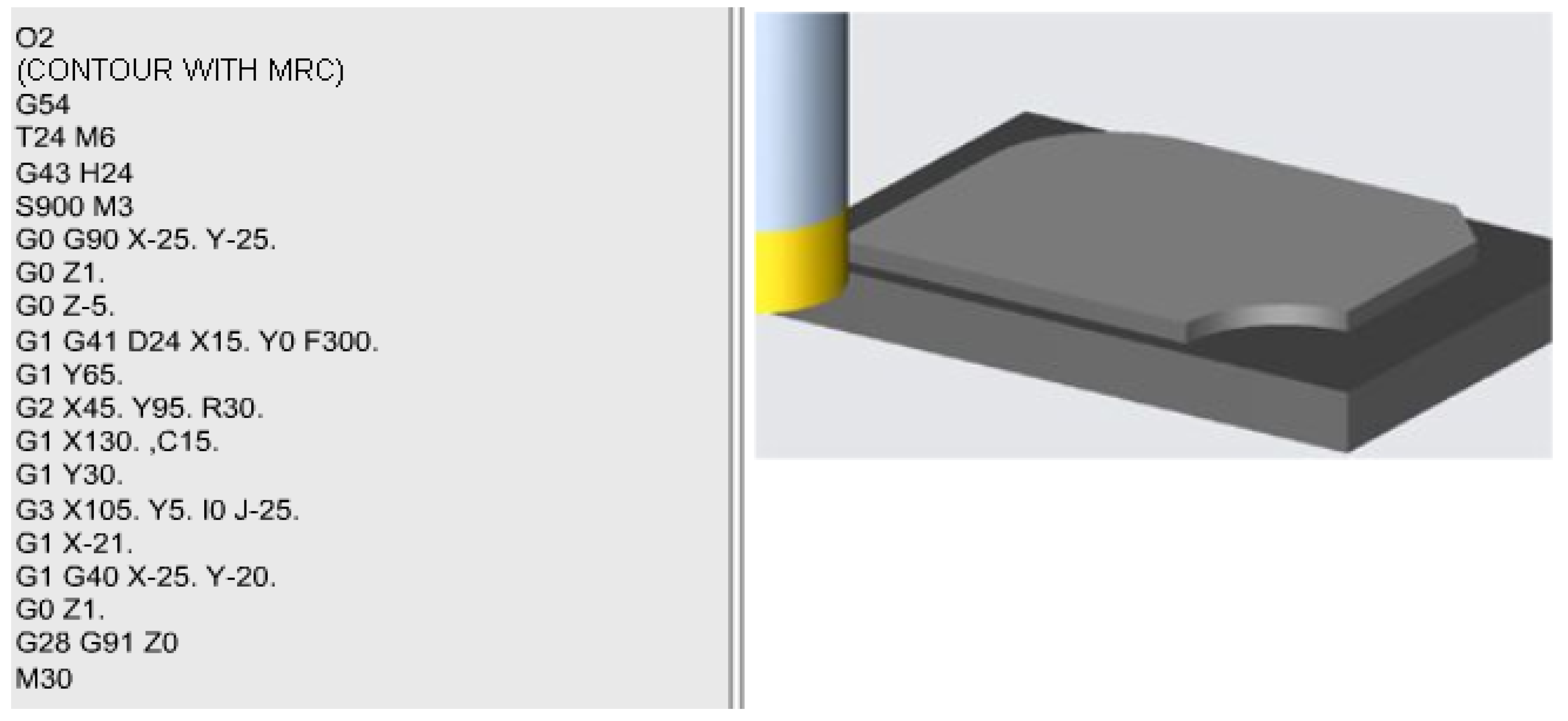
The following program (
Figure 10) describes the contour processing of a piece by combined milling and the kinematic description of the various component elements (connecting radius, chamfers, etc.) using the facilities and Keller – Haas subroutines described in previous works see. [
13] , [
15,
17] The first five instructions in the program are the initialization instructions whose meaning was presented in case studies 3.1 and 3.2 (with application in complex parts [
18],described above.
G0 G90 X-25. Y-25. – fast forward movement to the point of the mentioned coordinates which represents the starting point for contour processing.
G0 Z1. - movement also with rapid advance in the vertical direction along the OZ axis up to the amplitude of 1mm above the piece.
G0 Z-5. – descent, also with rapid advance, to elevation -5 in the direction of the OZ axis, elevation at which the level plane is located on which contour processing is done. It should be noted that this descent can be done with rapid feed because the tool is outside the part (X-25, Y-25).
G1 G41 D24 X15. Y0 F300 – is a movement with work feed to the coordinate point (X15,Y0) with tool offset on the left ( G41 ), and the tool offset on the diameter ( D24 ) is assigned to tool number 24 defined in instruction 3, ( T24 ). Processing is done with a feed speed of 300 mm per minute.
G1 Y65. – fast forward movement keeping the X15 coordinate (which is no longer included in the phrase) until reaching the Y65 point; basically, the rectilinear side from the left of the part is processed up to the entrance to the connection.
G2 X45. Y95. R30 – Represents the machining of the R30 taper radius from the top left corner of the part.
G1 X130. , C15. - Together with the immediately following instruction (G1 Y30.) this phrase allows processing the 15 x 15 mm chamfer (chamfer C15 ).
G3 X105. Y5. I0 J-25. - processing by circular interpolation of the connection radius from the lower right corner by interpolation in the opposite direction of the clock hands CCLW, the resulting surface being the concave surface as shown in
Figure 5.
G1 X-21. – Machining the portion of the lower straight line while keeping Y which is no longer mentioned in the sequence but has a value of 5 mm (Y5), and the tool will exceed the contour of the piece to the left entering quadrant 2 with negative values for X.
Obs. This is a precautionary measure to force the tool out of the part, because in the next sequence the radius correction is canceled and the tool is given freedom to retract to the machine zero point.
G1 G40 X-25. Y-20. – Canceling the tool correction ( G40 ) and retracting the tool to the previously mentioned safety position, outside the part. Retraction is done with a work advance of linear interpolation G1 (the last asset mentioned in the program, F300, so 300mm/min). The next three sequences are the reset and end of program sequences and are common sequences to all programs and they were described above in case studies 3.1 and 3.2.
