Submitted:
08 May 2023
Posted:
09 May 2023
You are already at the latest version
Abstract
Keywords:
1. Introduction
2. UAV Communication Subsystems
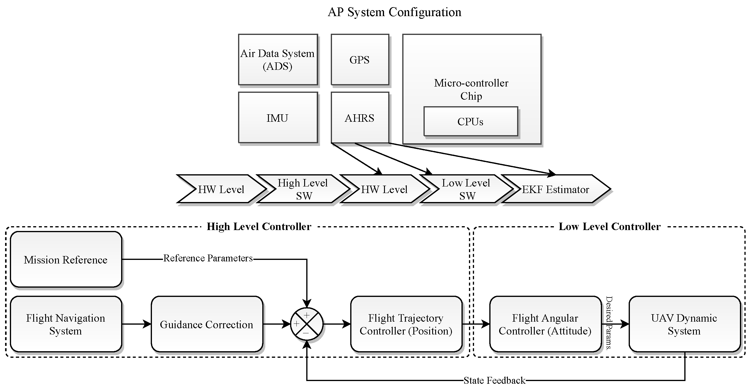
2.0.1. Autopilot (AP) and Digital Systems
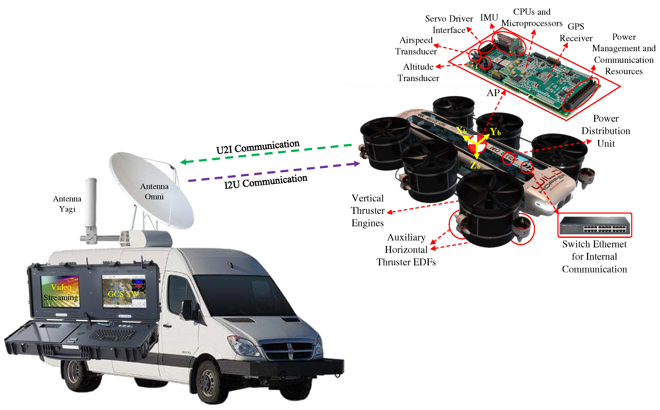
2.0.2. Communication System
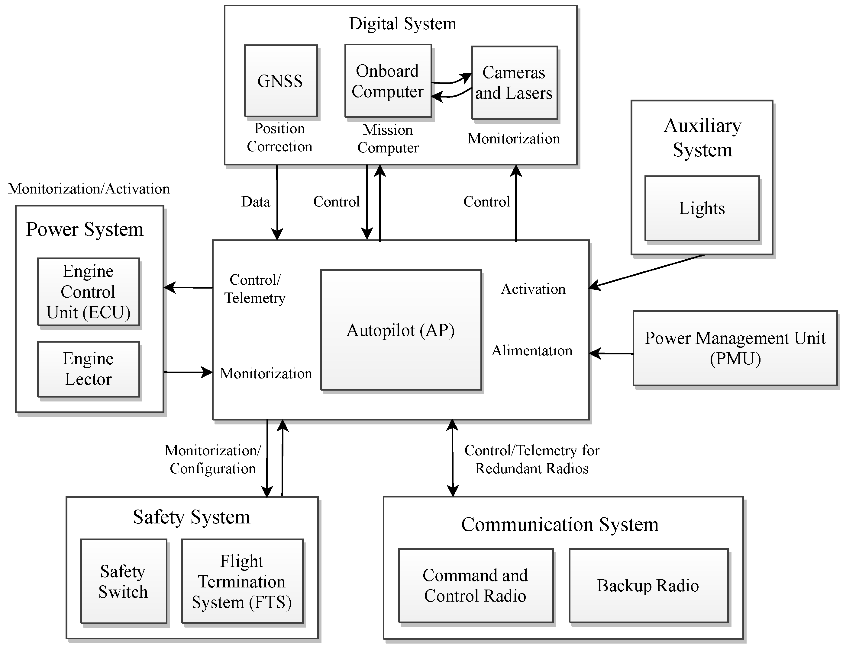
3. Dynamic System and Control
3.1. Aerodynamics Analysis
3.2. Control Strategy
4. Results
5. Conclusions and Future Work
Author Contributions
Acknowledgments
Conflicts of Interest
Abbreviations
| UAV | Unmanned Aerial Vehicle |
| UAS | Unmanned Aerial System |
| H2020 | Horizon 2020 |
| GCS | Ground Control Station |
| SMC | Sliding Mode Controller |
| TVC | Thrust Vectoring Control |
| FANET | Flying ad hoc Network |
| IBN | Infrastructure-Based Network |
| WSN | Wireless Sensor Network |
| WMN | Wireless Mesh Network |
References
- Tzu, S. The art of war. In Strategic Studies; Routledge, 2008; pp. 63–91.
- Zeng, Y.; Zhang, R.; Lim, T.J. Throughput maximization for UAV-enabled mobile relaying systems. IEEE Transactions on communications 2016, 64, 4983–4996. [CrossRef]
- Castrillo, V.U.; Manco, A.; Pascarella, D.; Gigante, G. A Review of Counter-UAS Technologies for Cooperative Defensive Teams of Drones. Drones 2022, 6, 65. [CrossRef]
- Nawaz, H.; Ali, H.M.; Laghari, A.A. UAV communication networks issues: a review. Archives of Computational Methods in Engineering 2021, 28, 1349–1369. [CrossRef]
- Li, B.; Fei, Z.; Zhang, Y. UAV communications for 5G and beyond: Recent advances and future trends. IEEE Internet of Things Journal 2018, 6, 2241–2263. [CrossRef]
- Mozaffari, M. Wireless Communications and Networking with Unmanned Aerial Vehicles: Fundamentals, Deployment, and Optimization. PhD thesis, Virginia Tech, 2018.
- Li, B.; Fei, Z.; Dai, Y.; Zhang, Y. Secrecy-optimized resource allocation for UAV-assisted relaying networks. 2018 IEEE Global Communications Conference (GLOBECOM). IEEE, 2018, pp. 1–6. [CrossRef]
- Behjati, M.; Zulkifley, M.A.; Alobaidy, H.A.; Nordin, R.; Abdullah, N.F. Reliable aerial mobile communications with RSRP & RSRQ prediction models for the Internet of Drones: A machine learning approach. Sensors 2022, 22, 5522. [CrossRef]
- Jawhar, I.; Mohamed, N.; Al-Jaroodi, J.; Agrawal, D.P.; Zhang, S. Communication and networking of UAV-based systems: Classification and associated architectures. Journal of Network and Computer Applications 2017, 84, 93–108. [CrossRef]
- Isaac, M.S.A.; Ragab, A.R.; Garcés, E.C.; Luna, M.A.; Peña, P.F.; Cervera, P.C. Mathematical Modeling and Designing a Heavy Hybrid-Electric Quadcopter, Controlled by Flaps. Unmanned Systems 2022, 10, 241–253. [CrossRef]
- Ale Isaac, M.S.; Luna, M.A.; Ragab, A.R.; Ale Eshagh Khoeini, M.M.; Kalra, R.; Campoy, P.; Flores Peña, P.; Molina, M. Medium-Scale UAVs: A Practical Control System Considering Aerodynamics Analysis. Drones 2022, 6, 244. [CrossRef]
- Luna, M.A.; Ale Isaac, M.S.; Ragab, A.R.; Campoy, P.; Flores Peña, P.; Molina, M. Fast Multi-UAV Path Planning for Optimal Area Coverage in Aerial Sensing Applications. Sensors 2022, 22, 2297. [CrossRef]
- Ragab, A.R.; Isaac, M.S.A.; Luna, M.A.; Flores Peña, P. WILD HOPPER Prototype for Forest Firefighting. International Journal of Online & Biomedical Engineering 2021, 17. [CrossRef]
- Isaac, M.; Naghash, A.; Mirtajedini, S. Control and guidance of an autonomous quadrotor landing phase on a moving platform. Proceedings of the IMAV Annual Conference of Autonomous Vehicles, Madrid, Spain, 2019, Vol. 29.
- Urban, D.; Kusmirek, S.; Socha, V.; Hanakova, L.; Hylmar, K.; Kraus, J. Effect of Electric Ducted Fans Structural Arrangement on Their Performance Characteristics. Applied Sciences 2023, 13, 2787. [CrossRef]
- Eltayesh, A.; Castellani, F.; Burlando, M.; Hanna, M.B.; Huzayyin, A.; El-Batsh, H.M.; Becchetti, M. Experimental and numerical investigation of the effect of blade number on the aerodynamic performance of a small-scale horizontal axis wind turbine. Alexandria Engineering Journal 2021, 60, 3931–3944. [CrossRef]
- Jacobsen, E.B. Modelling and Control of Thrust Vectoring Mono-copter 2021. p. 89.
- Abrego, A.I.; Bulaga, R.W.; Rutkowski, M. Performance study of a ducted fan system. American Helicopter Society Aerodynamics, Acoustics and Test and Evaluation Technical Specialists Meeting, 2002.
- Muehlebach, M.; D’Andrea, R. The flying platform–a testbed for ducted fan actuation and control design. Mechatronics 2017, 42, 52–68. [CrossRef]
- Karpinska, F.; Pachtrachai, J. Comparison of hexacopter and quadcopter performance for aerial photography. 2015 10th International Conference on Electrical and Electronics Engineering (ELECO). IEEE, 2015, pp. 867–871. doi:10.1109/ELECO.2015.7394554. [CrossRef]
- Reddy, R.S.; Dash, S.K. Design and Analysis of a Hexacopter for Heavy Lift Applications. International Journal of Engineering Research & Technology (IJERT) 2014, 3, 1352–1357.
- Tovar, D. Quadcopter vs Hexacopter: Pros and Cons. UAV Coach, 2018.
Disclaimer/Publisher’s Note: The statements, opinions and data contained in all publications are solely those of the individual author(s) and contributor(s) and not of MDPI and/or the editor(s). MDPI and/or the editor(s) disclaim responsibility for any injury to people or property resulting from any ideas, methods, instructions or products referred to in the content. |
© 2023 by the authors. Licensee MDPI, Basel, Switzerland. This article is an open access article distributed under the terms and conditions of the Creative Commons Attribution (CC BY) license (http://creativecommons.org/licenses/by/4.0/).


