1. Introduction
Designing and creating reconfigurable antennas that have a broad operating frequency range, are small in size, and have a soft visual impact are a very exciting challenge. One of the key advantages of optically transparent and reconfigurable printed Vivaldi antennas is that they can be integrated into a wide range of applications, such as smart windows, and smart glasses, without affecting the appearance of the device. Additionally, because they can be reconfigured to operate at different frequencies, they can be used for multiple wireless communication standards, such as 5G and 6G. Additionally, because the antenna can be reconfigured, it can be tuned to operate at different frequencies, making it more versatile than traditional fixed-frequency antennas. [
1,
2,
3,
4]. The trend in recent years has been to develop broadband frequency antennas or reconfigurable antennas that can serve multiple microwave applications from a single device. These antennas can be used for GPS, GSM, WLAN, and Bluetooth applications [
5,
6,
7,
8]. Additionally, 5G base stations require compact, reconfigurable antennas that can adjust radiation patterns to track users. This paper will describe the proposed transparent, reconfigurable, and broadband Vivaldi antenna in Section II, detail the fabrication process and characterization at microwaves in Section III, discuss experimental results in Section IV, and conclude in Section V.
2. Antenna design
The proposed reconfigurable wideband Vivaldi antenna was printed on a 25.4 mm x 25.4 mm x 0.2 mm fused quartz substrate (dielectric permittivity
εr = 3.75 and loss tangent tanẟ = 4x10
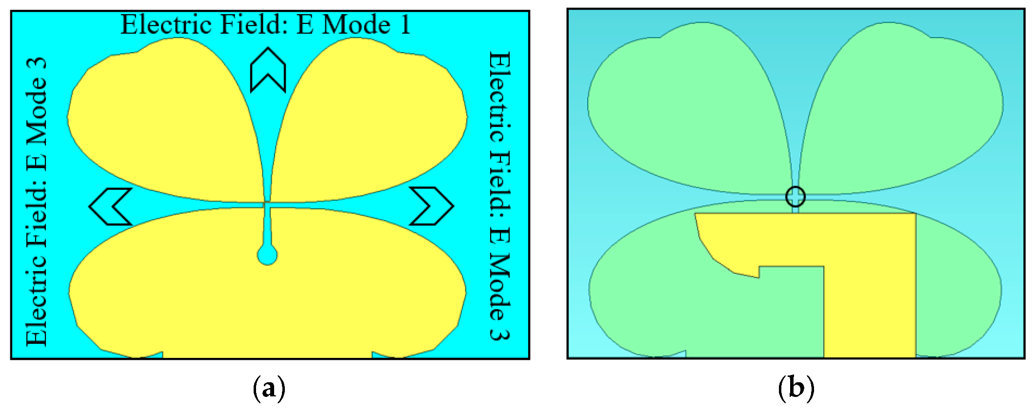
-4 at 24 GHz). It consisted of a 7.25 mm x 8.94 mm radiating element made of 2 distinctive parts (namely petals) and a specially designed ground plane that was printed on the front side of the substrate (
Figure 1a). The radiating element is energized by a transition between a slot and a micro strip line, which has a width of 3.1 mm and ends with a quarter circle with a radius of 0.6 mm, which is printed on the back side of the fused quartz substrate (as shown in
Figure 1b). On the front side of the substrate, three PIN diodes were integrated into tapered slot lines to achieve reconfigurable radiation patterns (as shown in
Figure 1a). The slot line along the y-axis is terminated with a circular slot with a radius of 0.22 mm (as shown in
Figure 1b).
Three PIN diodes, labeled D1, D2, and D3, are used to control the reconfigured slots to operate in three different modes. Mode 1 is achieved when D1 and D2 are in the ON state (acting as a short-circuit) and D3 is in the OFF state (acting as an open-circuit). Mode 2 is achieved when D2 and D3 are in the ON state and D1 is in the OFF state, and Mode 3 is achieved when D1 and D3 are in the ON state and D2 is in the OFF state. This is summarized in
Table 1.
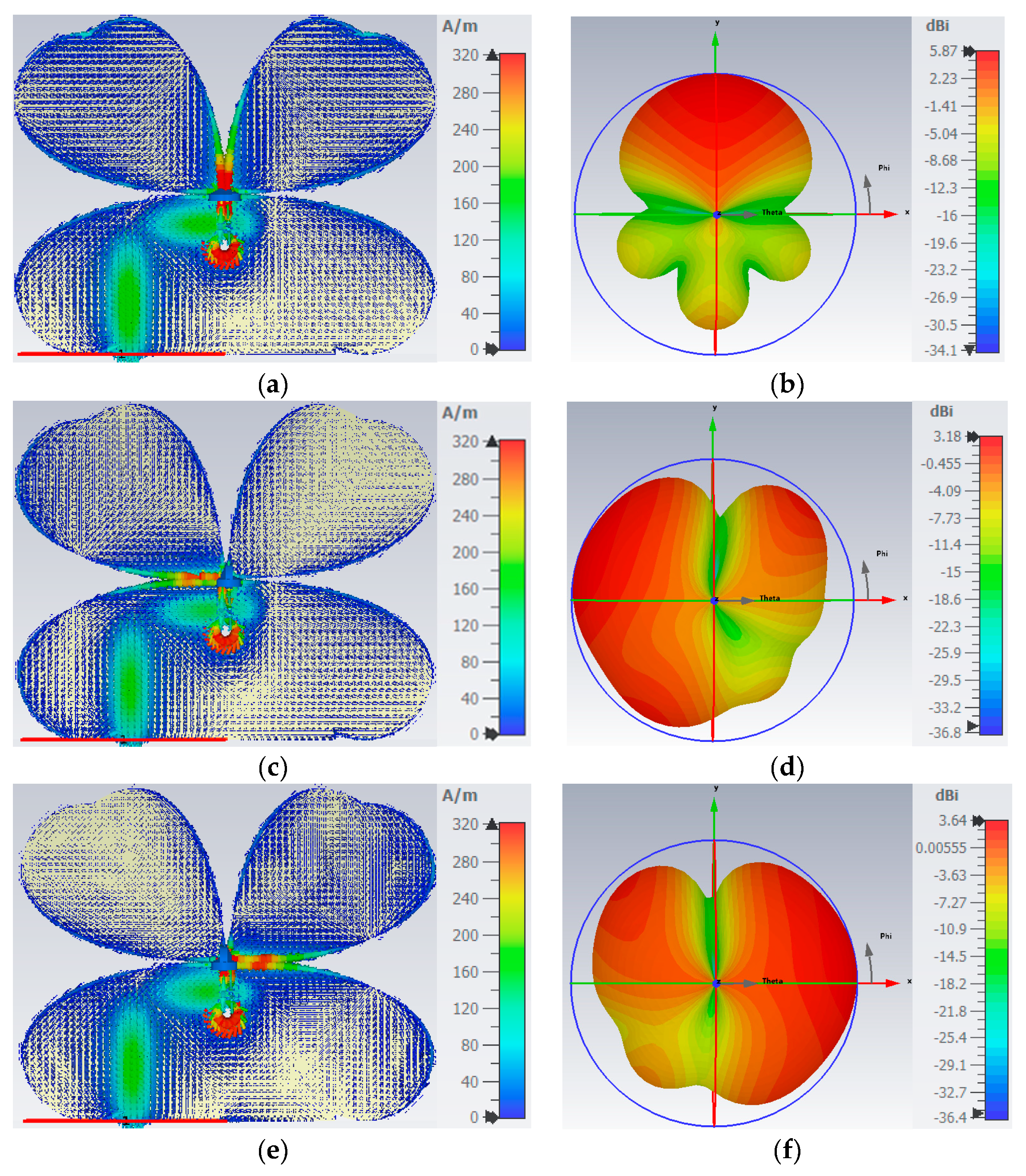
The current flow through the tapered slots is maximized at the edges (as seen in
Figure 2a,
Figure 2c, and
Figure 2e) and the direction of the radiating beam can be adjusted by directing the current through D1, D2, or D3 PIN diodes. In Mode 1, with D1 and D2 in the ON state, the beam radiates at an angle of ϕ = 90° (as shown in
Figure 2b). In Mode 2, the deviation of the current occurs on the left side of the tapered slot (as shown in
Figure 2c) and in Mode 3, the deviation occurs on the right side (
Figure 2e).
The radiation pattern of the Vivaldi antenna can be adjusted to cover a 300° by utilizing the three different modes, allowing for greater control and flexibility.
Mode 1, shown in
Figure 2b, has the highest gain of 5.9 dBi at 26 GHz, while Modes 2 and 3, shown in
Figure 2d and
Figure 2f respectively, have lower gains of 3.2 dBi and 3.6 dBi in the same frequency. The difference in gain values is a result of greater back-side radiation in Modes 2 and 3. It should be noted that the simulations were conducted using a continuous silver metal layer.
Figure 3 and
Figure 4 present the simulation outcomes of gain and efficiency for the three modes, which indicate a gain variation from 3.2 dBi to 5.9 dBi and efficiency from 80% to 92% at 26 GHz frequency.
3. Simulations Results
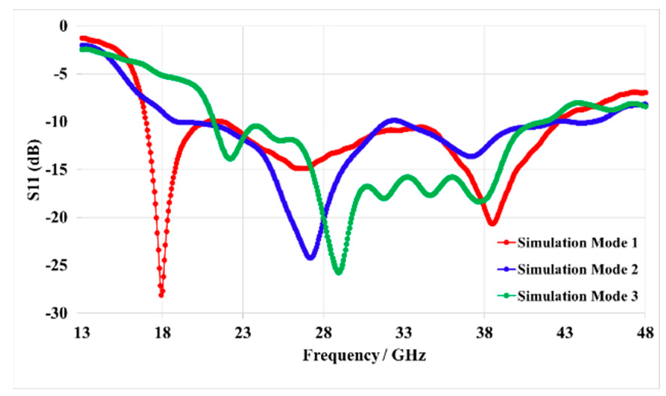
Due to the PIN diode used MA4AGP907 (beam-lead), all simulations consider the perfect PIN diode behavior (ON=Open circuit, OFF=Short-circuit). The S parameters are shown in
Figure 3, and correspond to very good matching antenna for the three modes.
Figure 4 illustrates the simulation results of the gain and efficiency performance in the three different modes, Mode 1, Mode 2, and Mode 3 of the antenna across a frequency range of 21-30 GHz.
4. Transparent Vivaldi Antenna Fabrication
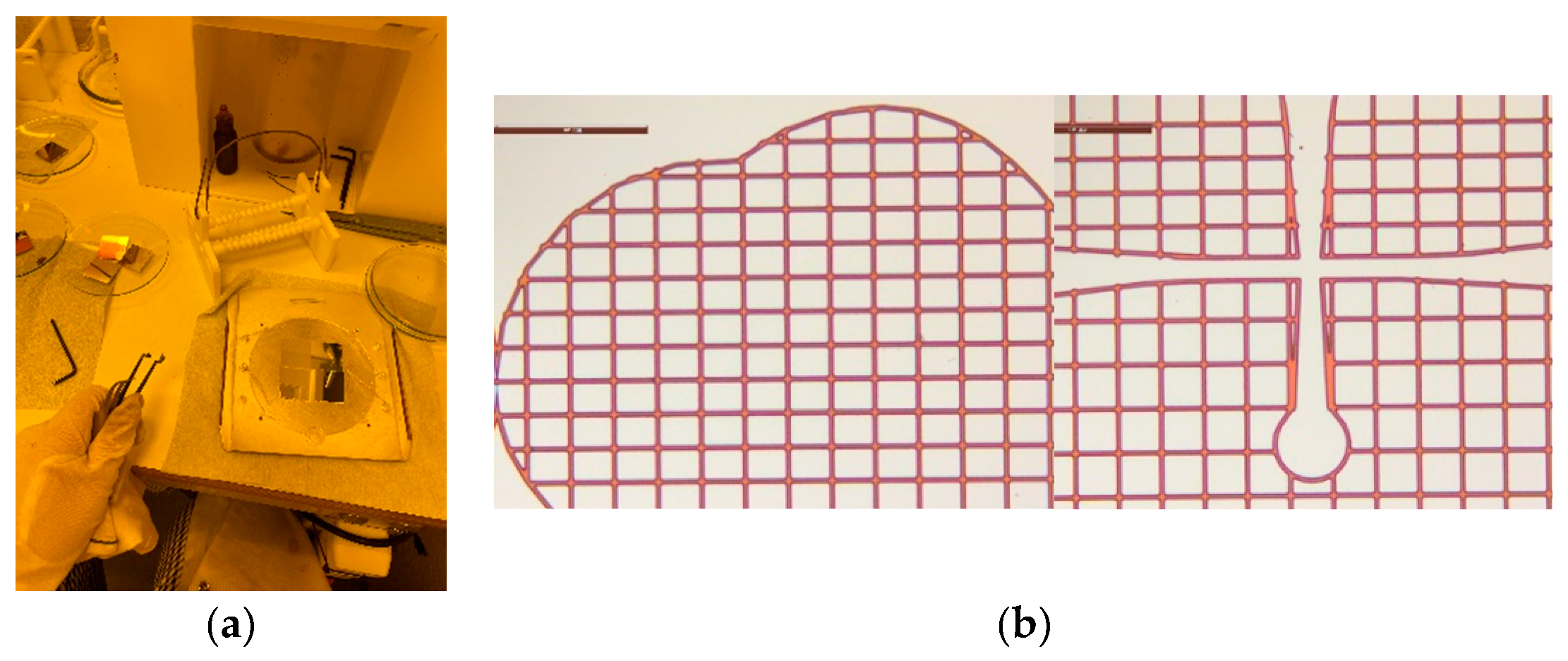
Three transparent mesh antennas have been created using a process described in [
4], which involves depositing a 1.35 µm-thick continuous silver film and a 5 nm-thick titanium adhesion film on a substrate using RF sputtering. Photolithographic wet etching is then used to create the antenna patterns with appropriate photomasks. The silver film was made three times thicker than the skin depth value (0.45 µm at 26 GHz) by using standard photolithographic wet etching processes and appropriate photomasks. During the photolithography process, careful alignment of the photomasks and the substrate is crucial to ensure the accuracy of the antenna. The resulting antenna is optically transparent, making it suitable for use in applications where visibility is important, such as in smart windows or heads-up displays. The distance between the antenna elements (pitch) affects the level of optical transparency, with wider pitch resulting in higher transparency levels (ranging from 66% to 89%). This transparency is measured using a UV-Visible spectrophotometer.
The process of creating a transparent antenna involves creating square apertures in the metal layers, with a specific pitch and metal strip width. In this case, the pitch is 150 µm and the metal strip width is close to 15 µm.
Figure 5 details such an antenna.
5. Active transparent antenna
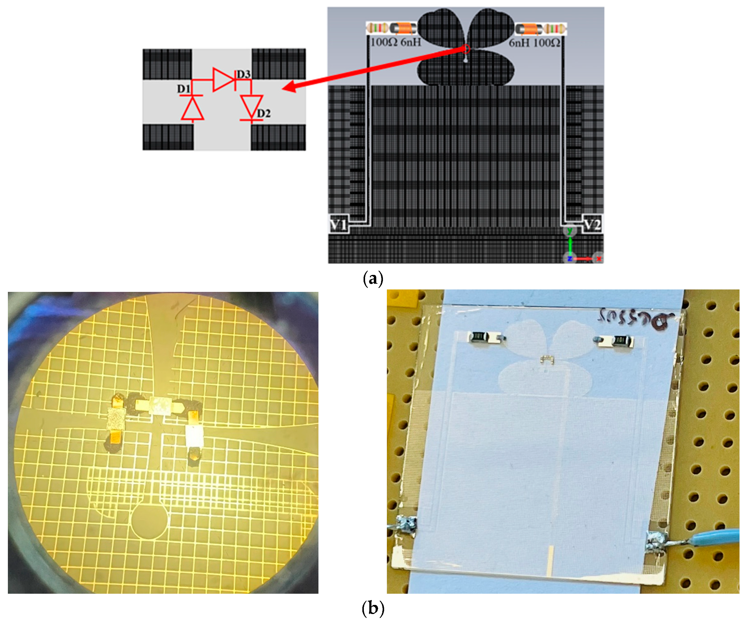
Three positive-intrinsic-negative (PIN) MA4AGP907 diodes were implemented as switches to provide the antenna beam switching (
Figure 6, and
Figure 7). PIN diodes are implemented as switches to provide beam switching capabilities and are connected in series to use only two DC supply voltages (V1 and V2) for the different modes is displayed in
Table 2. 200 µm-width biasing lines are positioned perpendicularly to minimize their impact on the radiation pattern, for each DC biasing line an inductors (L = 6 nH) and resistors (R = 100 Ω) are also used to block RF current and protect the diodes, respectively.
As indicated in
Table 2, to activate Mode 1, apply reverse bias to D1 and forward bias to D2 and D3. For Mode 2, apply reverse bias to D2 and forward bias to D1 and D3. And, for Mode 3, apply reverse bias to D3 and forward bias to D1 and D2. Modes 1, 2, and 3 refer to activation of upper radiating slot, left-sided slot, and right-sided slot respectively.
6. Results and discussion
The mesh antenna underwent an optical transparency test using a UV/Visible spectrophotometer. The results showed a transparency of 76% across the visible light spectrum of 400-800 nm. This confirms the high optical transparency of the mesh antenna.
Figure 6b displays the results of the test. The mesh antenna's ability to transmit visible light with minimal absorption ensures its suitability for optical applications. The high transparency is a testament to its quality and effectiveness.
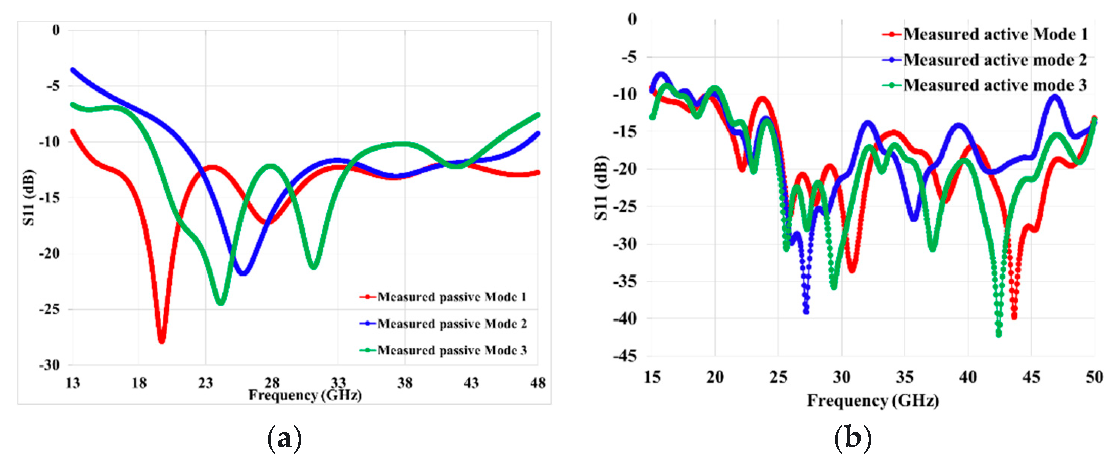
Figure 8 describes the comparison between simulations and actual measurements of the performance of a transparent antenna in different operating modes (1, 2, and 3). The results of the measurements given in
Figure 8 match the expected results from the simulations, showing that the antenna can operate within a frequency range of approximately 20 to 30 GHz with a low level of reflection (indicated by a magnitude of S11 lower than -10 dB) for both cases, passive and active antennas. However, some fluctuations, or ripples, in the experimental measurements may be observed due to errors in the measurement process or losses incurred by active components in the antenna. Despite these issues, the measurements provide evidence for the wide frequency bandwidth and overall performance of the transparent antenna.
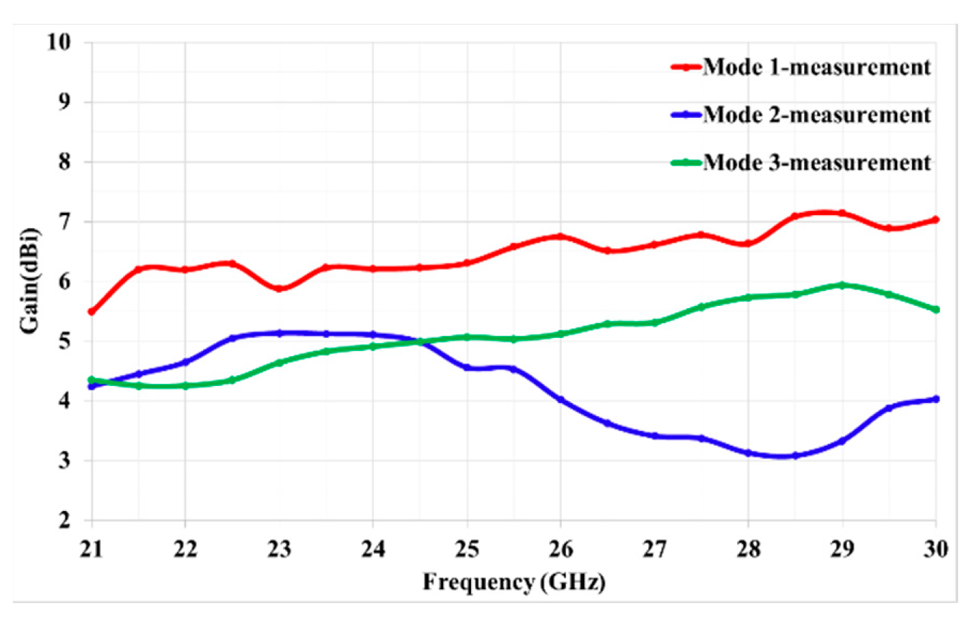
The measurement results for the gain of the antenna in each mode are depicted in the
Figure 9. Mode 1 shows the highest gain of 7.2dBi at 26GHz, while modes 2 and 3 have a peak gain of 5.1dBi at 24 GHz and 6dBi at 29GHz respectively. The difference in gain can be explained by the higher level of rear radiation in modes 2 and 3.
Figure 10 shows that by changing the DC bias of diodes, the orientation of radiation pattern change as expected.
7. Modes combination
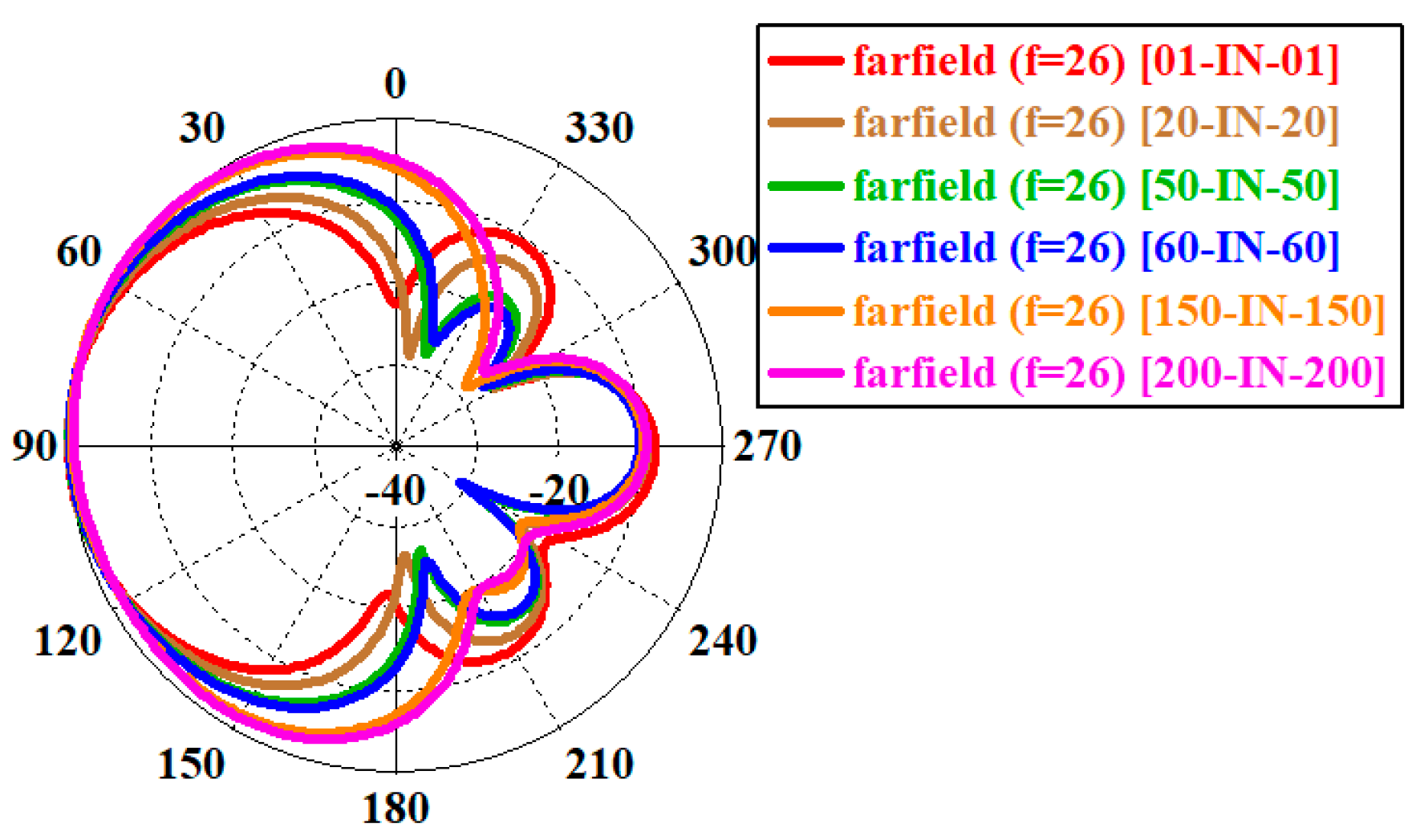
The radiation beams of mode 1 are more directional compared to the other two modes, as the ground plane serves as a better reflector for this mode. To achieve equalization of the radiation modes in our proposed structure, we modified the values of the PIN diodes bias, which act as variable resistors, to regulate the opening of the radiation beams for mode 1. To simulate the 2D diagrams for the first mode, we varied the resistor values on the right and left at a frequency of 26 GHz.
According to
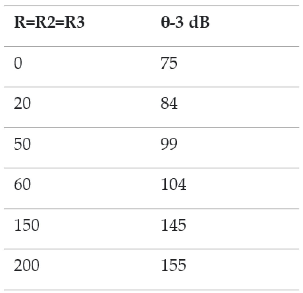
Figure 11, we have the ability to regulate the aperture of the beam. When the resistor value is X=0.01 Ω, the beam aperture is 75° at -3 dB. Conversely, when the resistor value is 200 Ω, the beam aperture increases to 155°, which is approximately twice the previous value. The table below illustrates the values of the resistors and their corresponding -3 dB beam aperture angles (θ-3dB).
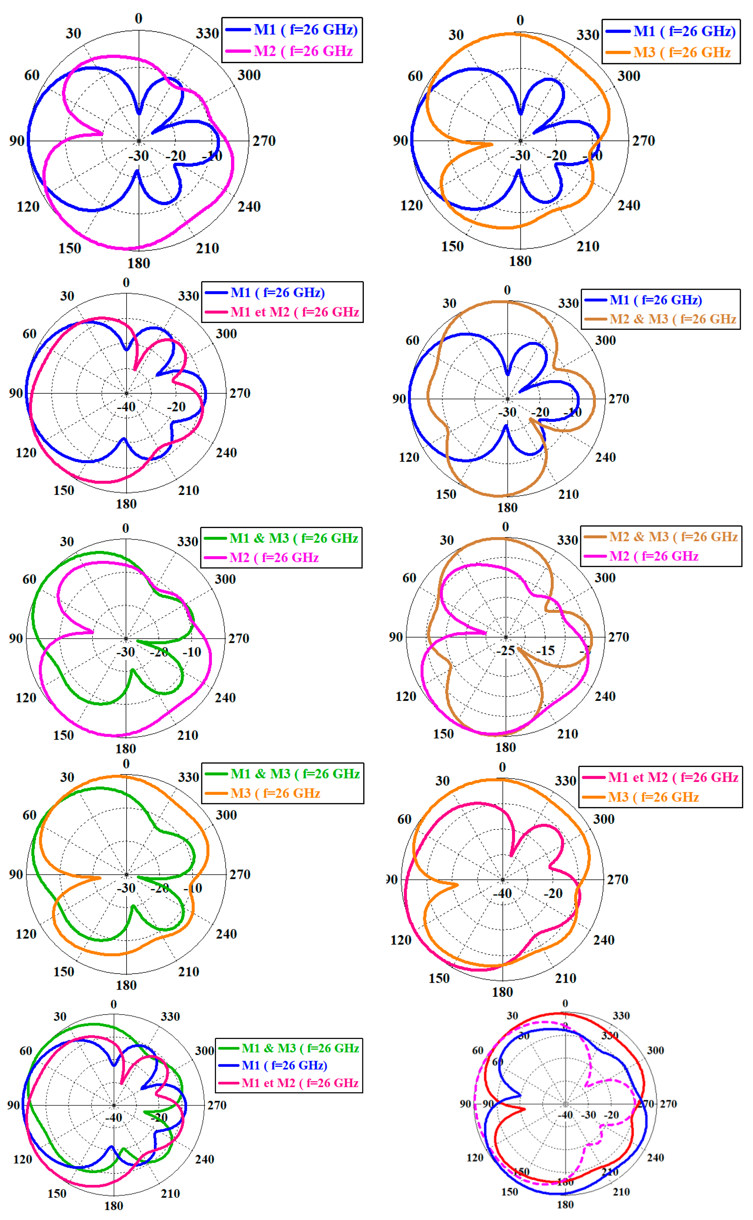
By referring to
Figure 12, we can observe the amalgamation of the three radiation modes, resulting in a coverage angle of 330°. However, the remaining coverage is obscured by the connector.
8. Conclusion
The design of a compact and transparent Vivaldi antenna, suitable for use in the 20-30 GHz microwave frequency range, has been achieved. The antenna boasts a high level of transparency, with 76% visible light transmission. The beam direction of the antenna can be adjusted up to 300° by activating specific PIN diodes. Therefore, Active transparent antennas can be utilized in 5G and 6G communication systems that need multi-beam and directional beam capabilities.
Author Contributions
Conceptualization, A.C. and M.H.; methodology, A.C. and M.H.; software, A.C.; validation, A.C., M.H.; investigation, A.C. and M.H.; data curation, A.C.; writing—original draft preparation, A.C.; writing—review and editing, A.C., M.H., X.C., Q.S., S.D., F.C.; visualization, X.X.; supervision, M.H.; project administration, M.H. All authors have read and agreed to the published version of the manuscript.
Data Availability Statement
Not Applicable.
Acknowledgment
This work is supported by the European Union through the European Regional Development Fund (ERDF), the Ministry of Higher Education and Research, the Région Bretagne, the Département des Côtes d’Armor and Saint-Brieuc Armor Agglomération, through the CPER Projects 2015-2020 MATECOM and SOPHIE / STIC & Ondes.
Conflicts of Interest
Declare conflicts of interest or state “The authors declare no conflict of interest.” Authors must identify and declare any personal circumstances or interest that may be perceived as inappropriately influencing the representation or interpretation of reported research results. Any role of the funders in the design of the study; in the collection, analyses or interpretation of data; in the writing of the manuscript; or in the decision to publish the results must be declared in this section. If there is no role, please state “The funders had no role in the design of the study; in the collection, analyses, or interpretation of data; in the writing of the manuscript; or in the decision to publish the results”.
References
- X. Castel, M. Himdi, and F. Colombel, “Comparison of the microwave performance of transparent monopole antennas made of different transparent conducting films,” in IEEE Conf. Antenna Meas. Appl. (CAMA), Sept. 2018, Västeras, Sweden.
- Martin, O. Lafond, M. Himdi, and X. Castel, “Improvement of 60 GHz transparent patch antenna array performance through specific double-sided micrometric mesh metal technology,” IEEE Access, vol.7, no.1, pp. 2256-2262, Jan. 2019. [CrossRef]
- H. A. Elmobarak, S. K. A. Rahim, M. Himdi, X. Castel, and M. Abedian, “A transparent and flexible polymer-fabric tissue UWB antenna for future wireless networks,” IEEE Antennas Wirel. Propag. Lett., vol.16, no.1, pp.1333-1336, May 2017. [CrossRef]
- Martin, C. Gautier, X. Castel, and M. Himdi, “Transparent and miniature FM antenna in printed technology,” Intern. J. Microw. Wirel. Technol., vol.10, no.1, pp.19-24, Feb. 2018. [CrossRef]
- Cherif, M. Himdi, S. Dakhli, X. Castel, and F. Choubnani, “Broadband reconfigurable Vivaldi antenna for 5G communication,” in Intern. Conf. IEEE WAMICON 2022, April 2022, Tampa, USA. [CrossRef]
- Delphine, M. Rijal Hamid, N. Seman and M Himdi, “Broadband cloverleaf Vivaldi antenna with beam tilt characteristics,” Int. J. RF Microw. Comput. Aided Eng., vol.30, no.5, pp.e22158, May 2020. [CrossRef]
- M. R. Hamid, and P. Gardner, “Vivaldi antenna with integrated switchable band pass resonator,” IEEE Trans. Antennas Propag., Vol.59, no.11, pp. 4008-4015, Nov. 2011. [CrossRef]
- S. Saleh, W. Ismail, I. S. Z. Abidin, M. H. Jamaluddin, M. Bataineh, and A. Alzoubi, “Compact reconfigurable ultra wide band and 5G narrow band Vivaldi tapered slot antenna,” in IEEE Intern. RF and Microw. Conf. (RFM), Dec. 2020, Kuala Lumpur, Malaysia. [CrossRef]
- R. Elmahraoui, R. Rais and T. Mourabit, “A new endfire phased array based on Vivaldi antenna for 5G applications,” in 19th Intern. Symp. Antenna Technol. App. Electromagn. (ANTEM), Aug. 2021, Winnipeg, MB, Canada. [CrossRef]
- J. Guo, S. Xiao, S. Liao, B. Wang, and Q. Xue, “Dual-band and low profile differentially fed slot antenna for wide-angle scanning phased array,” IEEE Antennas Wirel. Propag. Lett., vol.17, no.2, pp.259-262, Dec 2017. [CrossRef]
|
Disclaimer/Publisher’s Note: The statements, opinions and data contained in all publications are solely those of the individual author(s) and contributor(s) and not of MDPI and/or the editor(s). MDPI and/or the editor(s) disclaim responsibility for any injury to people or property resulting from any ideas, methods, instructions or products referred to in the content. |
© 2023 by the authors. Licensee MDPI, Basel, Switzerland. This article is an open access article distributed under the terms and conditions of the Creative Commons Attribution (CC BY) license (http://creativecommons.org/licenses/by/4.0/).
