1. Introduction
Management of inner pipe walls is important because defects on the inner wall of the pipe can interfere with facility operation and pose a threat to safety. To address this issue, several advanced technologies have been developed, such as endoscopes and pipe inspection robots. Pahwa [
1] came up with a technique that involves using a 360-degree camera to capture continuous footage of the interior of pipes and then stitching the images together. Kagami [
2] utilized Structure-from-Motion (SfM), a method that reconstructs 3D structures from 2D images, to identify the defects in the structure and inside of pipes. Duran [
3] discovered flaws within pipes by using a laser projector that casts a ring-shaped light onto the pipe wall and a neural network-based classification technique. Gunatilake [
4] suggested a mobile robot detection system that generates a 3D RGB depth map by using a stereo camera vision system coupled with an infrared laser profiling device to determine the presence of internal pipeline defects. However, using high-performance cameras and sensors as described above incurs considerable costs in terms of money and computation time.
Our proposed technique aims to generate images of the inner wall of a pipe by utilizing perspective images captured by a monocular camera sensor. As the images of the pipe wall that are captured while the sensor moves through the pipe are perspective images that project the wall from close to the camera to far away, we calculate the position of the corresponding wall on each pixel of the captured image while accounting for the focal length and the diameter of the pipe. To obtain the relationship between a point on the image plane and a point on the corresponding wall when the pipe and the image plane are perpendicular, we first derive the inverse perspective mapping (IPM) formula for a cylinder. IPM is a transformation technique that can be used to map a 3D object projected onto a 2D plane to a new position to create a new 2D image [
5,
6,
7]. A well-known application of IPM is in lane detection systems for autonomous driving, where it transforms the perspective view of a road image into a top view space, thus making lane detection easier and removing perspective distortion from the transformed 2D image. We use the IPM to restore the sharpness of the image at an appropriate restoration distance, as the sharpness decreases with the increasing distance of the wall from the camera. Moreover, to correct the distortion that occurs due to obstacles during the movement of the robot inside the pipe, we derive a generalized formula that considers the angle of the image plane. This IPM formula is based on the position of the vanishing point in the perspective image. While a common method for vanishing point detection is to find the intersection of the detected lines using the Hough transform [
8], this method may not always be applicable to perspective pipe images due to the absence of a line component leading to the vanishing point. Therefore, we use optical flow [
9,
10] for vanishing point detection inside the pipe. Optical flow is a vector field that captures the motion of objects between consecutive frames by identifying the displacement of corresponding pixels in adjacent frames. To capture a panoramic image of inner surface of a pipe, we first create a contour plot by using the vector magnitude of the optical flow formed in the perspective image of the pipe and detect circles. Next, we calculate the convergence position of these circles to detect the vanishing point. We then connect the transformed images using image stitching techniques [
11] and concatenate them into a panoramic image of the pipe wall. Ultimately, our technique generates a flat map of the pipe wall, which is convenient for crack detection. To validate our approach, we conduct numerical experiments using a 3D pipe model with arbitrary shape patterns and cracks inside.
2. Methods
2.1. Inverse Perspective Mapping
2.1.1. Perpendicular Image Plane
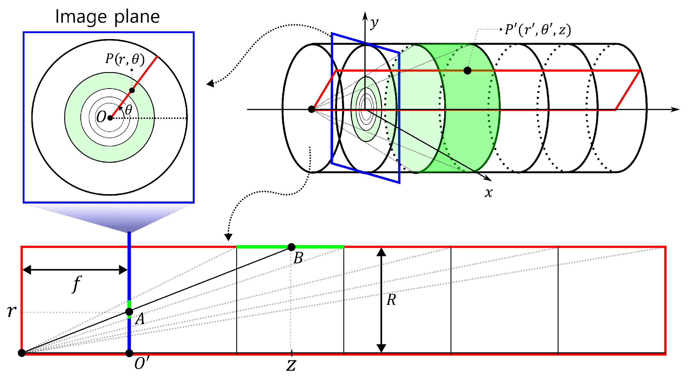
We assume that we are moving through a straight pipe of a constant diameter (
R) while capturing its interior using a camera. In
Figure 1, the image plane, which is marked by a blue rectangle, is shown perpendicular to the direction of flow inside the pipe. Suppose that circles are drawn at regular intervals inside the pipe, then the circles will be projected closer to the vanishing point as the camera moves further away from them. When representing the coordinates of the pipe wall in cylindrical coordinates and the image plane in polar coordinates, we can consider the following mapping between a point
on the image plane and a point
on the pipe wall:
where
and
(const.).
The red rectangle in
Figure 1 represents a plane that shows the cross-section of the pipe for a fixed
. The point
P on the image plane corresponds to point
A on the cross-section, while point
on the pipe wall corresponds to point
B. By a geometric proportion, we have the relationship
. Therefore, we obtain the following equation:
Here,
f is the focal length,
R is the radius of the pipe, and
r is the distance from a point on the image plane to the vanishing point. Since
f and
R are both constants, we can observe that
and
r are inversely proportional to each other, where
is the horizontal distance from the light source to the corresponding point on the pipe wall.
2.1.2. Inclined Image Plane
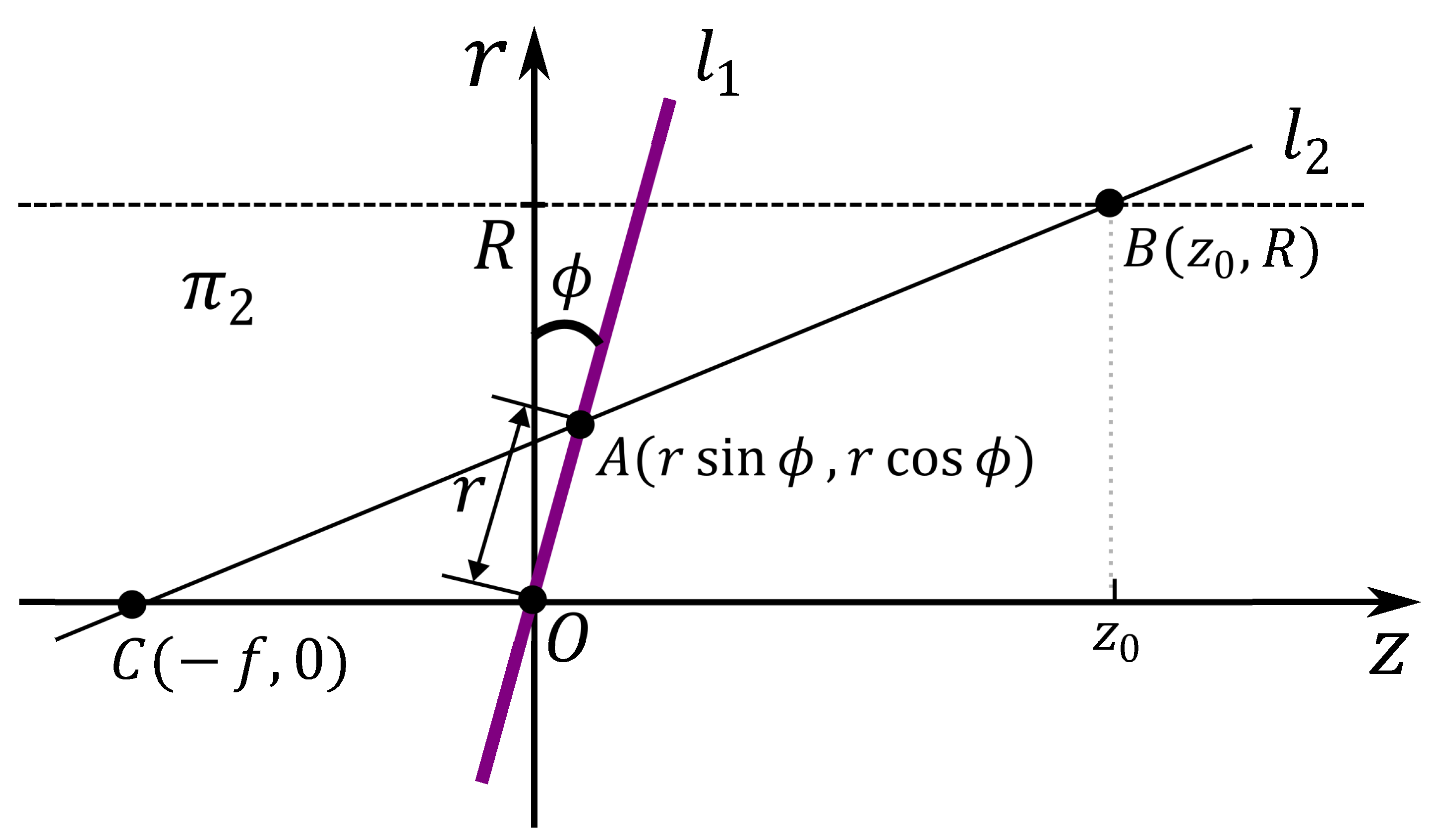
To consider the case where the camera direction does not match the flow direction of the pipe, we assume an image plane tilted by
with respect to the
x-axis, as shown in
Figure 2. We define the rectangular region
as the area where the interior of the pipe intersects the plane, which is created by rotating the half
-plane with
counterclockwise by an angle of
. Let
be the intersection line of
and the image plane,
. The angle (
) between
and the
z-axis is determined by
and
, where
represents the angle at which the image plane rotates around the
x-axis. Therefore, Equation (
2) needs to be modified to include both
and
as variables. As a result, point
P on the image plane corresponds to point
C on the cross-sectional plane, and the depth
z of point
D on the wall varies with the values of
and
, which depend on the position of
C. These relationship can be derived as follows:
Here,
f is the focal length,
R is the radius of the pipe, and
r is the length of
. The detailed derivation of the equation is given in Appendix
A and
B. Note that when
,
or
, Equation (
3) reduces to the same as Equation (
2).
2.2. Image Stitching
To generate a complete interior wall image of the pipe by connecting the images converted to a 2D wall, we use the panoramic image stitching technique [
11,
12]. This image stitching technique finds common features among multiple images taken of the same location or object and connects them into a single image. We use the SIFT (Scale-Invariant Feature Transform) method to identify corresponding points between two images, analyze the geometric relationship between the image pairs, and establish the transformation necessary to align and convert one image to another. Considering that the resolution of the images captured inside the pipe decreases with increasing observation depth, we carefully select and crop specific regions of the captured images for the purpose of image stitching, with the aim of obtaining optimal results despite the decreasing resolution.
2.3. Vanishing Point Detection
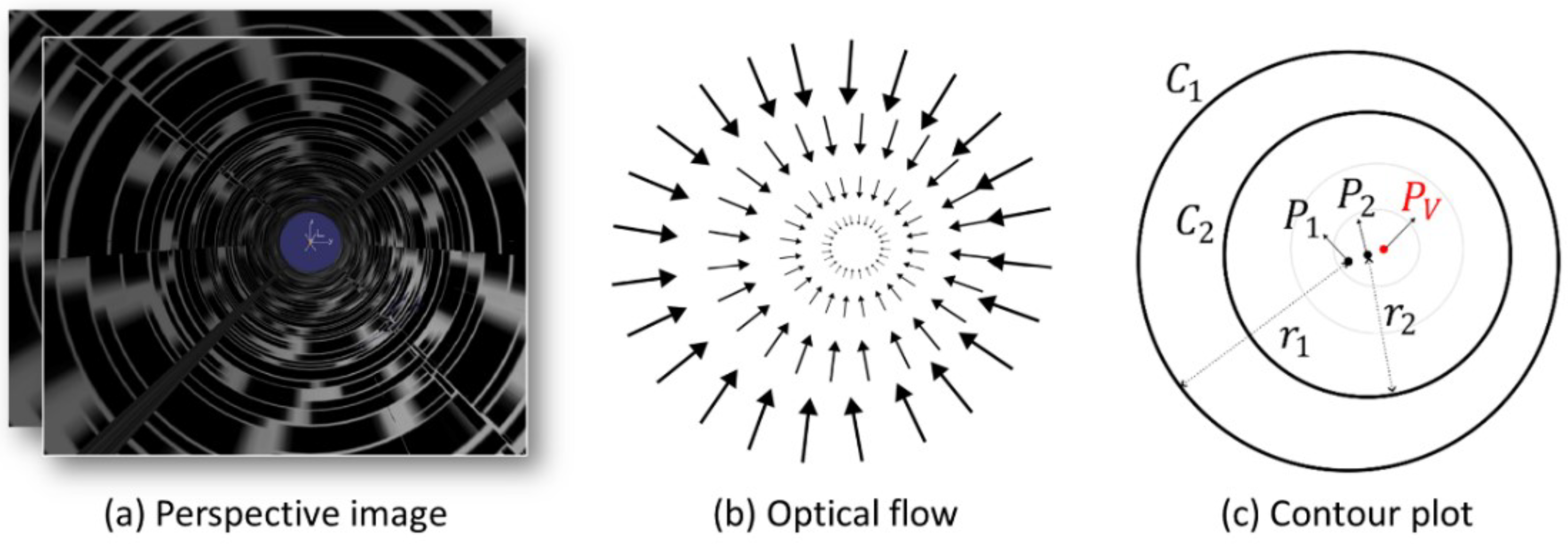
We detect the vanishing point using optical flow obtained from a sequence of perspective images.
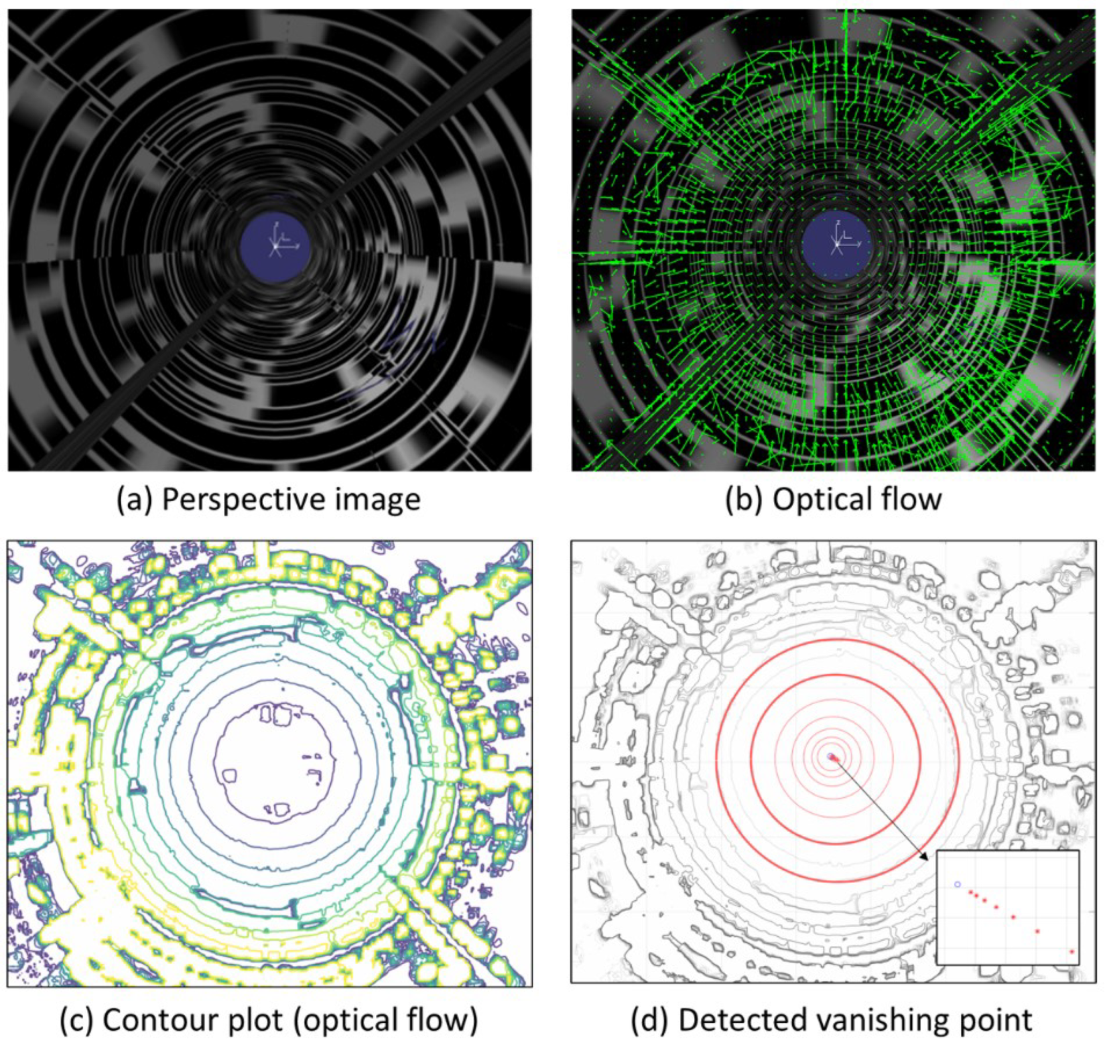
Figure 3 shows a conceptual diagram explaining the method of detecting the vanishing point. Optical flow is calculated for two consecutive perspective images obtained during movement inside the pipe, as shown in
Figure 3a. As can be seen in
Figure 3b, each vector in the optical flow has a direction toward the vanishing point, and the size decreases as it approaches the vanishing point. Theoretically, the maximum intersection point of the optical flow vectors is the optimal position for estimating the vanishing point. However, in practice, this method’s accuracy is often limited by minor errors in the vectors, which can lead to significant positional deviations in the vanishing point estimation. Therefore, we instead generate a contour plot for the magnitudes of the optical flow vectors, as shown in
Figure 3c. Circles are generated along the pipe wall in this contour plot. We select two circles among the circles generated around the vanishing point. Various methods for automatically detecting circles in images have been studied [
13,
14], but in the present study, we manually select three points on each of the two contours we want to choose on the contour plot to detect the circles. For the two detected circles
and
with respective centers
and
and respective radii
and
(where
), we use an infinite geometric series to calculate the position of the vanishing point
as follows:
where
.
2.4. Algorithm
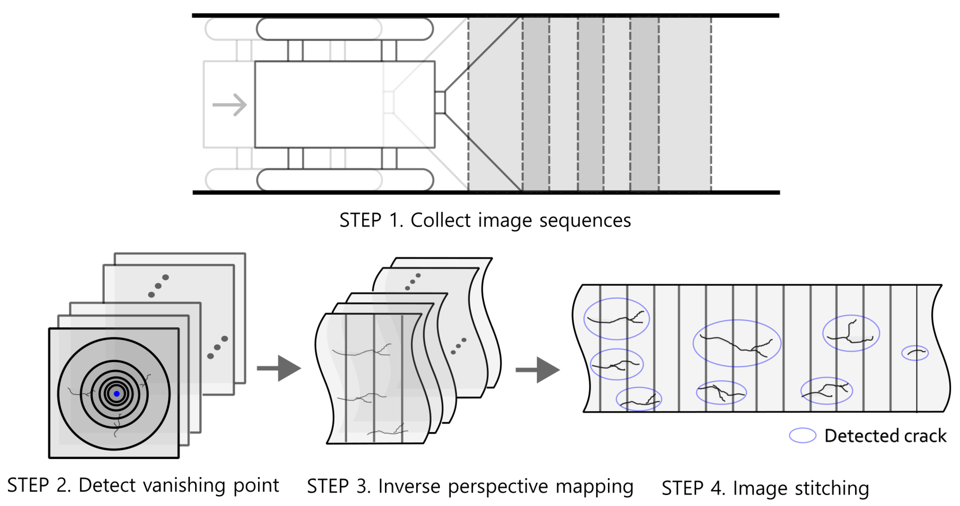
As depicted in
Figure 4, the overall algorithm we propose for creating a panoramic image of the inside wall of a pipe is as follows:
STEP 1. Collect an image sequence of the inside of the pipe while moving through the pipe.
STEP 2. Compute the optical flow for the consecutive images and generate a contour plot for the optical flow magnitudes. Select two circles from the contour plot and determine the vanishing point location using Equation (
5).
STEP 3. Obtain images of the pipe wall corresponding to each perspective image for the collected image sequence using Equations (
3) and (4).
STEP 4. Stitch the transformed images together using image stitching to create a panoramic image and detect cracks.
3. Results
To validate our method, we generated a sufficiently long 3D pipe using CATIA and inserted images with irregular patterns and cracks on the inner wall of the pipe. The diameter of the pipe was 350 mm and the focal length was 420 mm. We extracted a total of 50 perspective images by moving 40 mm inside the pipe while capturing images. We considered cases where the shooting angle was perpendicular to the direction of the pipe and cases where the pitch angle was tilted by degrees.
3.1. Vanishing Point Detection
Figure 5 illustrates the process used to detect the vanishing point using optical flow for a sequence of perspective images obtained by traversing inside the pipe model. The optical flow is calculated using the perspective image sequence shown in
Figure 5a, and the green arrows in
Figure 5b represent the optical flow (note that the white dot in the center here is not the vanishing point but simply the coordinate axis.) As the vectors move closer to the center, their size decreases, while their magnitude increases as they move outward, with errors in direction.
Figure 5c shows a contour plot of the magnitude of the optical flow vectors. Several circles can be seen near the vanishing point. The two circles selected from the contour plot, which are indicated by thick red lines in
Figure 5d, were used to create circles by selecting three points for each circle on the contour plot. In
Figure 5d, the two circles marked with bold red lines are selected from the circles observed in the contour plot. We generated the circles on the contour plot by selecting three points for each of the two circles. The red circles within the selected circles are drawn based on estimates of the centers and radii of the two selected circles. We can see that the centers of the circles converge to the blue vanishing point in the magnified image at the bottom right of
Figure 5d.
3.2. Inverse Perspective Mapping
3.2.1. Perpendicular Image Plane
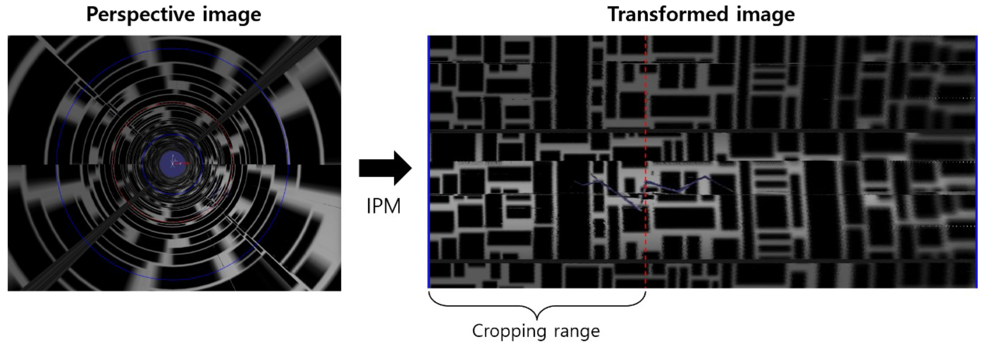
The left side of
Figure 6 shows a perspective image when the image plane is perpendicular to the direction of the pipe. Two circles (blue line) with radii
and
were generated based on the vanishing point to set the area to be transformed. The right image in
Figure 6 shows the resulting image plane that has been transformed using Equation (
2). We used the
function in MATLAB to pass RGB values to corresponding positions. As can be seen in the transformed image in
Figure 6, as we move toward the right, deeper areas of the pipe are represented, thus resulting in decreased resolution and slight image distortion. Therefore, in this experiment, we set the cropping area to points satisfying
, where
r is the distance from the vanishing point to the image plane.
Figure 7 shows the results of connecting the transformed images using image stitching, thus enabling easy identification of crack positions inside the pipe.
3.2.2. Inclined Image Plane
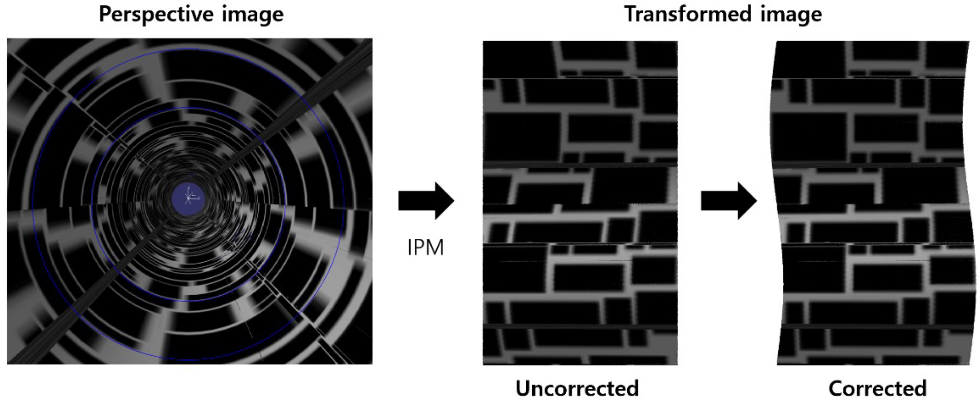
Figure 8 on the left shows a perspective image obtained when the image plane is tilted by 0.1 degrees in pitch. The blue circle represents the cropping range. If we use Equation (
2) without considering the tilt of the image plane, the resulting image is distorted as shown in the middle image in
Figure 8. However, when we use Equations (
3) and (4) to consider the tilt of the image plane, the transformed image no longer has a rectangular boundary and instead has a wavy shape, and the image distortion disappears. To perform actual image stitching, we set the cropping range to exclude the wavy area and accordingly calculated the internal square.
4. Conclusions and Discussion
Herein, We proposed a method for generating a flattened view of the inner wall of a pipe by transforming perspective images obtained from inside the pipe. First, we utilized the optical flow technique on a sequence of perspective images to generate contours and identify the vanishing point by calculating the positions of converging circles. Next, we rotated the cross-section around the vanishing point to determine the inverse projection point corresponding to a point on the image plane. To correct image distortion caused by the tilting of the image plane, we derived the IPM equation for the tilted image plane by considering the intersection of the image plane and the cross-sectional plane. Numerical experiments confirmed that the perspective images obtained from a 3D pipe model were successfully restored to images of the pipe wall by IPM, and that image distortion was effectively corrected even when the image plane was tilted. This paper did not propose a method for estimating the tilt angle of the image plane. The tilt angle of the image plane could be estimated by directly measuring the tilt angle using IMU sensors, or by estimating the tilt angle of the image plane using the position of the vanishing point. It is expect that this can be further developed and empirically validated through subsequent research.
Author Contributions
Conceptualization, S.-S.Y. and H.-S.L.; methodology, S.-S.Y. and H.-S.L.; software, S.-S.Y.; validation, S.-S.Y.; resources, H.-S.L.; writing—original draft preparation, S.-S.Y.; writing—review and editing, H.-S.L.; visualization, S.-S.Y.; project administration, H.-S.L.; funding acquisition, H.-S.L. All authors have read and agreed to the published version of the manuscript.
Funding
This paper was supported by Joongbu University Research & Development Fund, in 2022.
Institutional Review Board Statement
Not applicable.
Informed Consent Statement
Not applicable.
Data Availability Statement
Data is available from the authors upon reasonable request.
Conflicts of Interest
The authors declare no conflict of interest.
Appendix A. Derivation of Equation (3)
To determine the projection of a point (
A) on the wall (
B) from the image plane, we consider the line
on the cross-sectional plane (
) as shown in
Figure A1. Here,
is the intersection of the image plane (
) and the cross-sectional plane (
), while
O is the vanishing point on the image plane. Let
C be the light source, then,
A is projected onto the point
B on the wall, and the line passing through these three points is denoted as
. The two lines are then expressed as follows:
Since point A lies on both
and
, we obtain the following equation:
Solving the equation for
yields the following expression:
Figure A1.
Correspondence between a tilted image plane and the interior wall surface of a pipe
Figure A1.
Correspondence between a tilted image plane and the interior wall surface of a pipe
Appendix B. Derivation of Equation (4)
We aim to obtain a relationship equation for
, which is determined by the rotation angle
of the cross-sectional plane (
) and the tilt angle
of the image plane (
), as shown in
Figure 2. Let
and
be the normal vectors to planes
and
, respectively. We can obtain the rotated normal vectors by applying the rotations of
and
to the original normal vectors, respectively, as follows:
The direction vector
u of
is the cross product of
and
, which can be expressed as follows:
Now, considering the relationship between u and the direction vector
of the
z-axis, we have:
Thus, we obtain the following equation:
References
- Pahwa, R.S.; Leong, W.K.; Foong, S.; Leman, K.; Do, M.N. Feature-less stitching of cylindrical tunnel. In Proceedings of the 2018 IEEE/ACIS 17th International Conference on Computer and Information Science (ICIS); pp. 502–507.
- Kagami, S.; Taira, H.; Miyashita, N.; Torii, A.; Okutomi, M. . 3D pipe network reconstruction based on structure from motion with incremental conic shape detection and cylindrical constraint. In Proceedings of the 2020 IEEE 29th International Symposium on Industrial Electronics (ISIE); pp. 1345–1352.
- Duran, O.; Althoefer, K.; Seneviratne, L.D. Automated pipe defect detection and categorization using camera/laser-based profiler and artificial neural network. IEEE Trans. Autom. Sci. Eng 2007, 4, 118–126. [Google Scholar] [CrossRef]
- Gunatilake, A.; Piyathilaka, L.; Tran, A.; Vishwanathan, V.K.; Thiyagarajan, K.; Kodagoda, S. Stereo vision combined with laser profiling for mapping of pipeline internal defects. IEEE Sens. J. 2020, 21, 11926–11934. [Google Scholar] [CrossRef]
- Oliveira, M.; Santos, V.; Sappa, A.D. Multimodal inverse perspective mapping. Inf. Fusion 2015, 24, 108–121. [Google Scholar] [CrossRef]
- Nieto, M.; Salgado, L.; Jaureguizar, F.; Cabrera, J. Stabilization of inverse perspective mapping images based on robust vanishing point estimation. In Proceedings of the 2007 IEEE Intelligent Vehicles Symposium; pp. 315–320.
- Jeong, J.; Kim, A. Adaptive inverse perspective mapping for lane map generation with SLAM. In Proceedings of the 2016 13th International Conference on Ubiquitous Robots and Ambient Intelligence (URAI); pp. 38–41.
- Lutton, E. , Maitre, H., & Lopez-Krahe, J. Contribution to the determination of vanishing points using Hough transform. IEEE Trans. Pattern Anal. Mach. Intell. 1994, 16, 430–438. [Google Scholar]
- Horn, B.K.; Schunck, B.G. Determining optical flow. Artif Intell. 1981, 17, 185–203. [Google Scholar] [CrossRef]
- Fortun, D.; Bouthemy, P.; Kervrann, C. Optical flow modeling and computation: A survey. Comput Vis Image Underst 2015, 134, 1–21. [Google Scholar] [CrossRef]
- Brown, M.; Lowe, D.G. Automatic panoramic image stitching using invariant features. Int. J. Comput. Vis 2007, 74, 59–73. [Google Scholar] [CrossRef]
- Wei, L.; Zhong, Z.; Lang, C.; Yi, Z. A survey on image and video stitching. Virtual Real. Intell. Hardw. 2019, 1, 55–83. [Google Scholar]
- Ye, H.; Shang, G.; Wang, L.; Zheng, M. A new method based on hough transform for quick line and circle detection. In Proceedings of the 2015 8th International Conference on Biomedical Engineering and Informatics (BMEI); pp. 52–56.
- Yuen, H.K.; Princen, J.; Illingworth, J.; Kittler, J. Comparative study of Hough transform methods for circle finding. Image Vis. Comput. 1990, 8, 71–77. [Google Scholar] [CrossRef]
|
Disclaimer/Publisher’s Note: The statements, opinions and data contained in all publications are solely those of the individual author(s) and contributor(s) and not of MDPI and/or the editor(s). MDPI and/or the editor(s) disclaim responsibility for any injury to people or property resulting from any ideas, methods, instructions or products referred to in the content. |
© 2023 by the authors. Licensee MDPI, Basel, Switzerland. This article is an open access article distributed under the terms and conditions of the Creative Commons Attribution (CC BY) license (http://creativecommons.org/licenses/by/4.0/).
