1. Introduction
Recent developments in computing power and pattern recognition methods have driven the emergence of viable clinical and non-clinical neuroengineering applications based on scalp electroencephalography (EEG). These applications [
1] include, but are not limited to, seizure state prediction [
2,
3], sleep stage analysis [
4], cognitive workload assessment [
5], motor imagery-based Brain Computer Interface (BCI) systems [
6,
7], clinical BCI systems [
8,
9], multi-modal and multi-brain computer interfaces [
10], brain-controlled vehicles [
11], EEG-based home control [
12], virtual reality [
13], and interactive virtual environments [
14]. However, one of the main challenges in the deployment of these technologies to the end-users is the lack of mobile, low-cost, user-friendly EEG-based BCI systems as most current commercial EEG amplifiers and BCI headsets are prohibitively expensive, lack interoperability, and do not offer high signal quality nor closed-loop operation critical for BCI applications [
15]. To address these and other challenges to the translation of BCI systems, it is important to use multiple criteria for the design of neural interface systems.
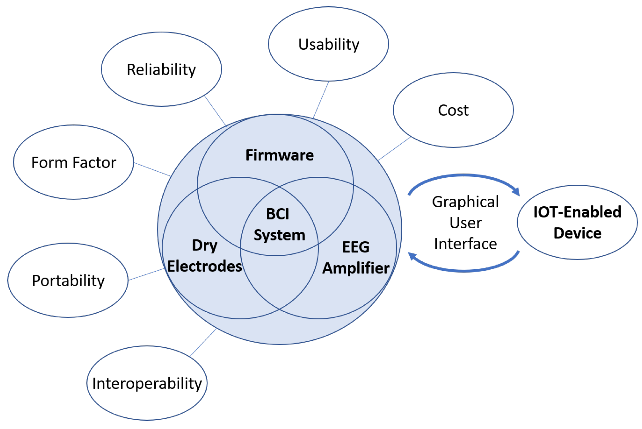
Figure 1 depicts the proposed criteria for the design of a closed-loop BCI system.
Portability and interoperability both affect the type of EEG/BCI applications that can be considered. Most commercial EEG systems are tethered to immobile processing hardware, making it difficult to deploy outside of the clinic or laboratory. A portable and wireless EEG system is highly preferred so it can be used more naturally and during mobile applications. Additionally, a system design that only provides control of a single device or the analysis of a single protocol significantly limits the potential for EEG and BCI systems, so a generalized control or analysis framework is preferred over a task- or protocol-specific system.
Usability, form factor, and reliability all significantly affect the user’s experience. Current commercial EEG systems are generally difficult to set up and use. This is a critical challenge for applications that will be used by the public as a complex system set up may be too difficult or take too long for an untrained user to operate without technical or expert assistance. A difficult challenge in the design of an EEG headset is accommodating the many different head sizes and shapes, and hair types and styling, but designing many different variations may not be economically feasible nor desirable for a commercial system. While a one-size-fits-all design is preferable, the ability for the system to be adaptable must be emphasized early in the design process and heavily tested in ecological settings. Moving this technology to low-cost hardware will increase accessibility, but, if the system is not reliable, the resulting user frustration may lead to product abandonment. Therefore, extensive software and hardware benchtesting must be performed to ensure reliability.
Outside of factors that affect design considerations and the user’s experience, the ability for the system to process EEG quickly and effectively is a necessary condition for complex EEG applications. This necessity is due to the fact that EEG suffers from a low signal-to-noise ratio, low spatial resolution, and high prevalence of artifacts, such as eye movement, eye blink, and motion artifacts. Many of the commonly used signal denoising methods are not suitable for real-time or mobile applications, so the selection of on-chip effective real-time signal denoising methods is a crucial decision that should be considered early on in the development process. Once the EEG signals are denoised, a neural decoder or neural classifier is commonly employed to extract valuable information, e.g., motor intent, from the brain signals acquired with EEG [
1,
16]. However, most current EEG systems do not provide the decoding functionality necessary for implementing closed-loop BCI applications without additional hardware and software. The above challenges provided the motivation for the development of the proposed EEG-based BCI headset.
While there are low-cost commercial dry EEG amplifier systems available on the market, none meet the criteria outlined above. The Ultracortex Mark IV EEG headset from OpenBCI [
17] is a popular open-source EEG headset design and is sold for a relatively low cost (
$399.99 for the user to 3D print the headset,
$899.99 for the 3D printed and assembled version at the time of publication of this report). However, each headset electrode holder must be manually manipulated for each user, which is not as user friendly as a design that employs a single manipulator for headset adjustments. Additionally, the OpenBCI headset does not provide processing onboard with the amplifier. Instead, it requires a separate computational unit for signal processing. The Muse 2 system [
18] is one of the lowest cost commercial amplifiers available (
$249.99) and includes a software application that provides standard biofeedback. The major drawback with the Muse 2 system is that, for raw EEG data collection and processing, an annual subscription must be purchased. Additionally, the Muse 2 system only has two forehead sensors and two sensors located behind each ear, which limits the potential applications for systems based on the Muse. Like the OpenBCI Mark IV headset, the Muse 2 system does not have processing onboard the headset, meaning a separate computing unit must be employed. While the market for commercial EEG amplifiers is expanding, there are no suitable commercial systems that meet the specifications required for more complex EEG applications. For a recent review of portable EEG devices with wireless capability, see [
19].
The rest of the paper is organized as follows:
Section 2 will describe the methods, which includes details and reasoning for hardware and software selection and development, as well as the methodology for system validation.
Section 3 presents the results of the system validation tests, including bench-testing and human participant validation in an ecological setting.
Section 4 provides a discussion on crucial design decisions and the development of the system generally, and Section 5 details our conclusions.
2. Methods
The target technical specifications for the system are presented in
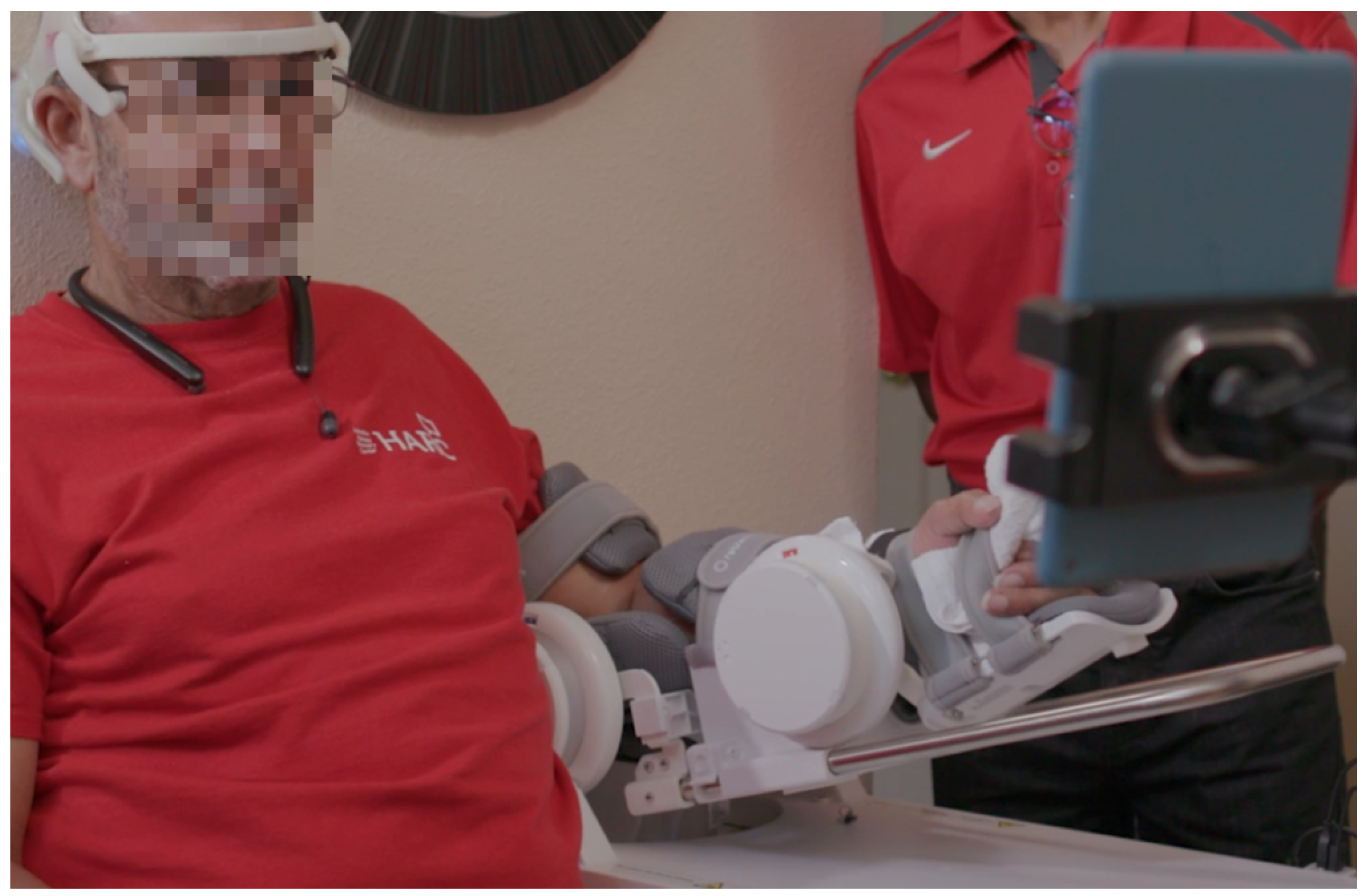
Table 1. A BCI-robotic system, including IOT enabled robotic device and a tablet with a custom graphics user interface (GUI), is presented as an example of deployment in a neurorehabilitation application with
Figure 2. The following section will detail the user-centered design of the headset, the development of the software, and the approach followed for bench-testing and experimental validation with human participants for the system. Written informed consent for the experimental procedures, which were approved by the University of Houston and University of Texas Health Science Center at Houston institutional review boards, was obtained from each participant.
2.1. Headset Design
Proper headset fit for the users is a critical factor affecting the system’s performance, but most headsets on the market do not fit as well as research-grade soft EEG caps [
20,
21]. To date, traditional soft EEG caps are still the best option in terms of accommodating both head size and shape variations [
22,
23]. The wide range of variations in human body biometrics demands the flexibility and adjustability in designing a more accommodating headset. Anthropometry data is widely used as a reference of variations to design products with optimized fit, comfort, functionality, and safety [
24]. In terms of size management, there are two different approaches. One approach is to offer the headset in different sizes to fit a wide range of users. Another approach is to offer a single size with adequate adjustments in multiple degrees to fit all users. Previous research in the development of a one-size-fits-all headset has found success, providing support for this approach [
25,
26].
One important requirement in the design of mobile devices is the need for single-handed device interaction as the headset will likely be used by people with limited attention span and upper limb and/or hand impairments, including reduced mobility and hand dexterity (e.g., older individuals and persons with chronic stroke [
9]). These physical limitations significantly influence the details of the design, the mechanical controls, and the overall form factor. As indicated in other studies, hardware design influences the user’s interaction with the device [
27]. For this reason, the design process should include a detailed ergonomic evaluation to ensure all controls are intuitive for one-hand use.
As a device to be used directly by consumers, general usability factors should be considered and optimized, including overall weight, adjustability, operational clarity and accuracy, user comfort, and aesthetic [
28]. Additionally, a good fixation of scalp and skin electrodes should be provided for reducing the contact impedance between the electrode and the skin, which enhances signal-to-noise ratio [
23].
2.1.1. Headset Design Development
The headset design began by mapping out the essential electrode locations required by a motor imagery (MI)-based BCI system prototype. For this, findings of a closed-loop BCI-exoskeleton system developed for upper-limb stroke rehabilitation were used to define the target technical specifications [
9]. This clinical trial of a closed-loop BCI to control an upper-limb exoskeleton (BCI-EXO) therapy demonstrated that 80% of participants with chronic stroke showed motor improvements after 12 sessions of BCI-EXO therapy. Moreover, the study reported changes in slow cortical potentials, as measured via EEG, due to the BCI intervention [
9]. Thus, the BCI-EXO system specification dictated the number and locations of the EEG electrodes with a reference to the international 10–20 system provided by the American Clinical Neurophysiology Society guidelines [
29]. In the current design, five EEG electrode locations were selected for the EEG-based BCI system for robot-guided stroke rehabilitation ([
9,
30]). The locations include frontocentral scalp locations at FC3, FC1, FCz, FC2 and FC4 positions.
Dry EEG comb electrodes with 5mm extended prongs (Florida Research Instruments, Inc., Cocoa Beach, FL) were selected for this device to maximize usability. Comb electrodes [
31] are recognized as an effective solution for collecting EEG through longer hair conditions and the selected electrodes end in blunt tips for long-term wearing comfort. While these dry electrodes alone will likely go through users’ different hairstyles and/or hair types to reach the scalp, without a specific mechanism to secure and maintain a constant steady contact during use, it is still likely to fail the needs of most users and needed to be addressed during the design of the EEG electrode holders.
An additional technical requirement of the headset is the capability to measure eye movements and eye blinks using electrooculography (EOG) sensors, where outputs could be used as auxiliary control outputs or for real-time de-noising of the EEG signals. Ancillary experiments (to be reported elsewhere) provided support that three EOG sensors can be used to extract information about eye blinks and eye movements in the vertical, horizontal, and oblique axes with high accuracy. These EOG sensors are located at the right temple, the left temple, and directly above the participant’s left eye. Two reference sensors, one behind each ear, complete the set of electrodes/sensors available in the headset. The skin sensors are adjustable in position and orientation to adapt to and fit a wide range of face profiles and contours while maintaining a constant and steady contact.
2.1.2. Design with Anthropometric Data
Anthropometric data ([
32]) was used to determine the overall device size in relation to the range of head size variations. The sizing parameters are referenced from the measurements of the smallest (5th percentile female) to the largest (95th percentile male) head sizes. The key dimensions in design consideration are head breadth, circumference, and length. The size range in three dimensions provides a guide for the design of the adjustment mechanisms. The differences in head breadth, circumference, and length between the 5th percentile female and the 95th percentile male are 1.08 in., 3.5 in., and 1.62 in., respectively. A digital mannequin corresponding to the 5th percentile female was developed and then scaled up to the 95th percentile male. These two digital mannequin models served as the basis to build the headset model in a 3D digital SolidWorks environment.
Traditional anthropometry calculation is based on a uniform variation on several dimensions. For instance, if the head length increases, the head breadth is expected to also increase by a consistent ratio. In some cases, the head breadth and the head length do not follow the common ratio due to unique head forms. This characteristic was confirmed with the real-world data collection for this study, which helped to determine a more realistic range of deviation. Due to this discrepancy, the head breadth adjustment mechanism was designed to be independent of the head length adjustment mechanism. Based on the electrode mapping and the general mechanical adjustment concept, an initial headset structure was developed, which includes 3-degree of freedom adjustments with a sufficient range to fit 90 % of all users.
2.1.3. Design of the Overall Sizing Adjustment Mechanism
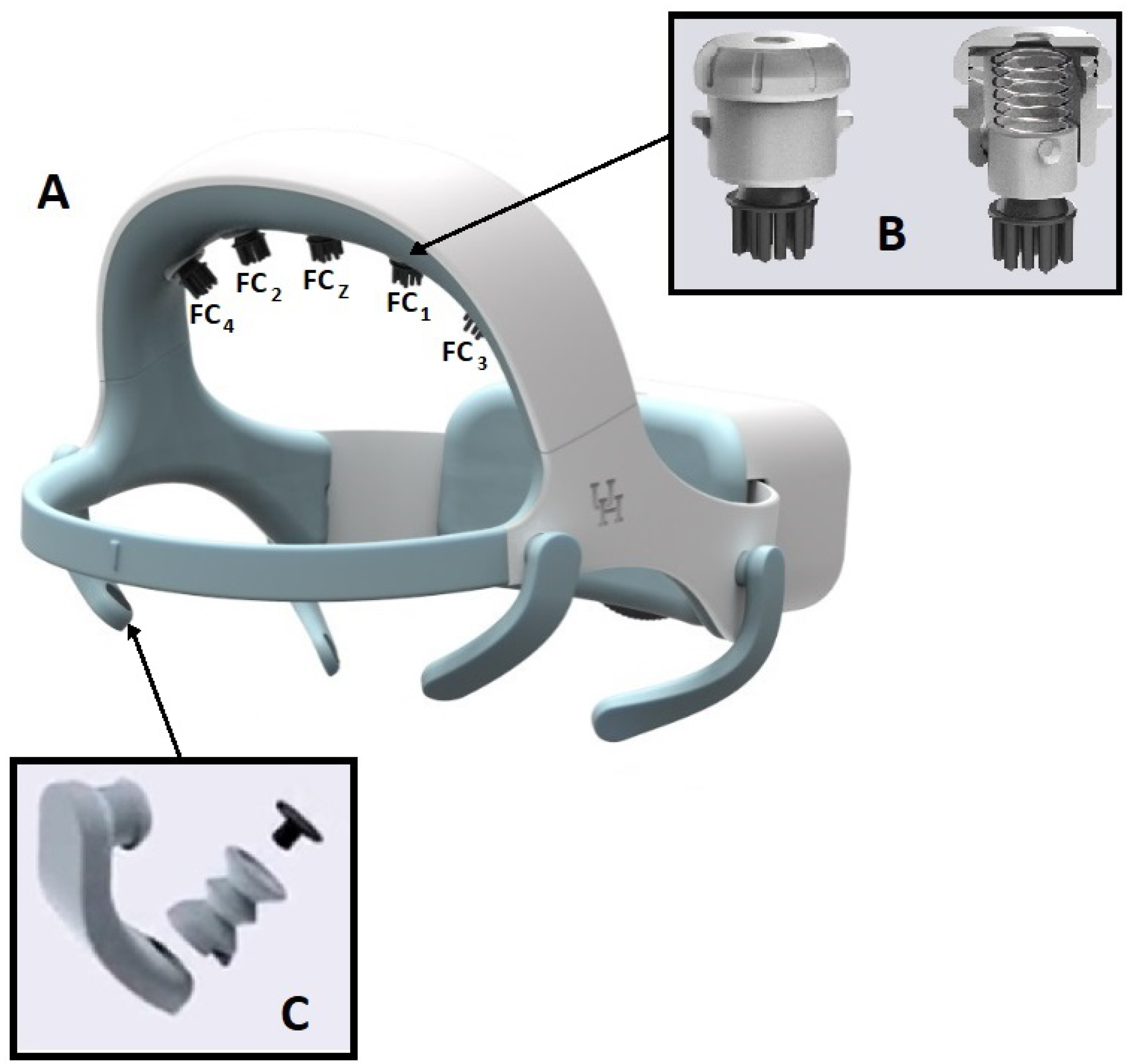
The final design (
Figure 3-A) utilizes a large dial (2.56" in diameter and 0.16" in thickness) in the back to adjust the overall circumference. The end of the ear-hub band is designed with gear teeth in a slot along the center-line. The left and right band overlap in the electrical box where they connect to the dial through the gear. The outer perimeter of the dial is shaped with fine convex diamond textures. The dial protrudes 0.22" out of the box and is designed to be turned easily in both directions with one finger. The dial’s clockwise rotation will extend two ear-hub parts to increase the headset circumference, whereas the counter-clockwise rotation will contract two parts to reduce the circumference. The overall circumference adjustment range is up to 3.5 inches. With a unique semi-flexible structure design, the headset is a one-size-fits-all solution.
2.1.4. Design of Dry Electrode Bracket with Vertical self-Adjustment
One challenge for EEG systems is to secure the electrodes and obtain good impedance for recordings. This is particularly important when using dry electrodes that cannot benefit from the viscous gel typically employed in wet electrode systems. For the dry electrodes that are placed over the user’s hair, it is common to experience unstable and noisy signals due to poor or intermittent contact between the electrode and the head scalp [
33,
34]. To meet this challenge, a unique self-positioning dry hair electrode holder was developed, as shown in
Figure 3-B. The holder is a proprietary (patent-pending) design for holding the designated electrode while providing a self-positioning rotational mechanical linkage that helps facilitate hair penetration of the electrode tips. The holder is 0.67" in diameter and 0.73" in height and is composed of three parts: the slider, the housing, and the cap. A screw and nut pair is used to fasten the electrode tip to the lower end of the slider. The fully shielded electrical wire is oriented between the screw and the electrode inner wall. The wire is routed through the center open space and the center hole on the cap. The slider is spring-loaded with a vertical travel of up to 10 mm. The electrode will move up and down along three spiral tracks, which allows for rotation of up to 120 degrees, to accommodate the regional changing head shape. This rotation will assist the electrode tip in moving through the user’s hair for improved contact with the scalp. The spring will help to maintain constant pressure between the electrode and the contact surface. The headset and electrode tip design are covered by US provisional patent #62857263.
2.1.5. Design of the Highly Adaptive EOG Sensor Holder
The headset system includes three electrooculography (EOG) sensors to track the users’ eye movements. Two sensors are positioned at the temple area along the side of each eye and a third is positioned directly above the user’s left eye. Typically, EOG skin sensors require the application of a conductive gel medium or tape to achieve steady constant contact with the skin. This headset is designed with accessibility for individuals with limited dexterity, so it’s undesirable to use sensors that require gel or tape. For that reason, the headset uses dry skin sensors.
A proprietary EOG sensor holder arm was developed to maintain a constant contact with the skin. The holder is composed of two parts: an arm and an EOG sensor plug (
Figure 3-C). The EOG sensor sits in the socket of the plug and is wired through the hollow arm, which is connected to the main board. The arm is printed in a medical grade skin-safe flexible resin and is designed with unique structure and form that makes it flexible while maintaining a constant pressure at the tip. The EOG plug is formed similarly to accordion pleats, which makes the plug compressible and can be flexed in any direction. The plug sits in an opening at the tip of the arm with an interference fit. The arm is rotatable around the connection on the structure to handle variations in face contours between users. The sensor plug’s spring motion applies a constant pressure to the skin surface to maintain a steady contact.
Figure 3.
A: Fully assembled one-size-fit-all (patent-pending) headset design. B: Dry electrode bracket. C: The skin sensor holder.
Figure 3.
A: Fully assembled one-size-fit-all (patent-pending) headset design. B: Dry electrode bracket. C: The skin sensor holder.
2.1.6. Headset Fabrication
The headset was designed with SolidWorks (SolidWorks 2019, Dassault Systemes, Vélizy-Villacoublay, France) and prototyped with a 3D printing process. Two types of printers were used in producing the prototype. An Artillery Sidewinder X1 FDM printer (manufactured by Shenzhen Yuntuchuangzhi Technology Co., Ltd in China) was used for the rigid structure printing, while a Saturn resin printer (manufactured by ELEGOO technology Co., Ltd in China) was used to print the flexible components. Two medical-grade thermoplastic resins were selected for the primary headset components: Taulman Nylon 910 (produced by Taulman3D Material in Indiana, USA) and Flexible 80A resin (produced by Formlabs in Somerville, Massachusetts). The Taulman Nylon 910 resin was used to build the rigid structural parts of the headset as it has similar strength and stiffness of polypropulene (PP), is FDA approved for skin contact, and the parts can be repeatedly bent while still returning to the original shape. The Flexible 80A resin was used to build all elastic parts and is also FDA approved for skin contact. The resulting flexible headset parts are stiff but soft with an 80A shore durometer. In addition to these two primary resins, there are two additional resins used for internal components. Esun PLA+ is used to fabricate the rear adjustment plate and dry EEG brackets while Polymax PC resin (Polymaker) is used to fabricate the ratchet gear and adjustment dial. The finalized design is presented in
Figure 3. From an aesthetic standpoint, an emphasis was made on creating a headset with clean and smooth external surfaces.
2.2. Design of the BCI Module
For the development of the device, LabVIEW (National Instruments Inc.) was selected as the primary coding language due to its extensive libraries and access to National Instruments’ hardware and software in the early phases of the design. We note, however, that any coding language could instead be used with the selected hardware, and in fact, a C++ version of the BCI firmware module has also been developed.
2.2.1. Processor Selection
For the minimal viable product (MVP), the BeagleBone Black – Wireless (BBB-W) [
35] was selected as the BCI processor for its low cost, availability, compatibility, and WiFi capabilities. Moreover, the availability of an open source LabVIEW toolkit (LINX LabVIEW [
36]) significantly reduced software redesign. The BBB-W has a 1 GHz ARM processor, 512 MB of DDR3 RAM, and 4GB of onboard storage, providing the computational power and storage space necessary for the BCI headset.
2.2.2. Design of the Custom Amplifier
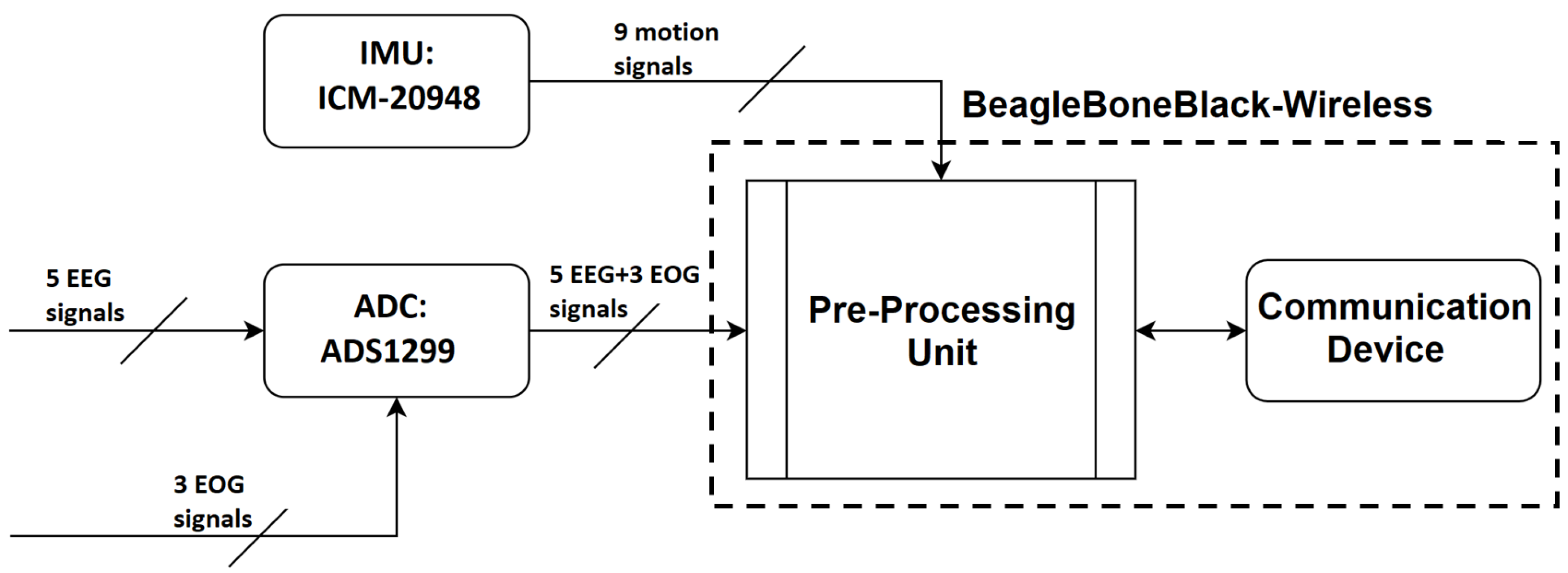
In EEG systems, an instrumentation amplifier acts to increase the amplitude of the detected signal to a level that can be further processed while an input buffer amplifier eliminates the need for impedance matching. Recently, the term amplifier has been broadened to also include the digitization of the analog signal through an Analog to Digital Conversion (ADC) chip, wireless communication, and motion detection System. In the proposed BCI system, there are three main components on the amplifier board: signal amplification, analog-to-digital conversion, and motion sensing.
Following the ADC step, it is necessary to pre-process the signals before transmission to the processing unit. These steps are summarized in
Figure 4.
With respect to the amplifier, there are some electrical characteristics that are expected on any EEG Amplifier [
37]. The ADS1299 chip from Texas Instruments [
38] was selected as it best matched the intended functionalities. Its characteristics are summarized in
Table 1 - section Amplifier Characteristics. The minimum requirements for the Inertial Measurement Unit (IMU), which provides motion sensing, were low energy consumption, a digital signal with more than 10 bits resolution, and the inclusion of a 3-axis accelerometer and a 3-axis gyroscope.
Table A1 in the Supplementary Material section presents the characteristics of the ICM-20948, which was selected because of it’s low error, low power consumption, and the availability of a magnetometer.
2.2.3. Manufacture of an Integrated Amplifier and Processing Board
The initial design included separate hardware modules for the pre-processing unit and the amplifier, with the use of Bluetooth for communication. However, the possibility of missing data packets in this crucial stage, Bluetooth’s line of sight requirement, and the computational capabilities of the BBB made this approach infeasible. Instead, the integration of the processing unit with the amplifier for signal collection and processing in the same location became a priority. For this combined unit, Serial Peripheral Interface (SPI) communication protocol is employed for communication between the processing unit and the directly connected amplifier.
2.2.4. Power System
The BBB-amplifier is powered by a relatively small 3.7V battery (BatterySpace p/n: PL-383562-2C single cell Polymer Li-Ion 3.7V-800mAh-2.96Wh, 64mm x 36mm x 4mm 18grams UL Listed, UN Approved battery) because portability was an important design factor [
39]. Based on the maximum expected power consumption of 1.48kWh from our system due to signal processing and constant communication with an external device (e.g., smart phone or tablet), the battery guarantees at least two hours of use. For charging of the battery, the procedure described in Section 4.1.7 "Battery Power Source/Charger" from the OSD3358 Application Guide [
40] was implemented for the system.
2.2.5. Software
This section details the main considerations, modular design, and resulting open and closed-loop characteristics for the system software. The primary focus throughout the software development was on maintaining real-time applicability and modularity, making modifications for different applications easier, thereby increasing the interoperability of the system.
Firmware
While LabVIEW real-time toolkits can sample at a constant frequency, this functionality requires the National Instruments onboard hardware clock, so setting a constant sampling frequency through LabVIEW is not possible on third-party processing boards. The firmware designed for the system instead employs spline interpolation, so the system can sample EEG and EOG at a rate set by the user, limited only by the computational power of the processing board.
Communication
The BeagleBone Black-Wireless processing board has both WiFi and Bluetooth capabilities (802.11b/g/n WiFi and Bluetooth 4.1 plus BLE), which are important in the goal of creating a completely portable system. This gives the BCI device the capability of communicating with any device that can be controlled remotely. As a test case, a BCI prototype was designed to communicate and control a third party WiFi-controlled device at a rate of 20 Hz. In addition to communicating with a WiFi-enabled device, to remain completely portable, the device includes a user interface that communicates with the system through the available LabVIEW web service. For the design of this interface, HyperText Markup Language (HTML), Cascading Style Sheets (CSS), Javascript (JS) were selected as the base languages for the interface since it can be used for the creation of a cross-platform interface that can be accessed from any browser and display that can handle the computational demands of the system. Displays and browsers tested include the iPhone (7+ or greater) and an Amazon Fire Tablet with the Google Chrome, Microsoft Edge, and Amazon Silk browsers.
Open-Loop Capabilities
The BCI device can be used to collect and save raw data from a participant according to an easily modifiable protocol. This data includes five EEG channels, three EOG channels, and accelerometer data from the IMU. Due to design considerations, the maximum sampling rate that can be achieved for raw data collection and saving is 80 Hz. To achieve this sampling rate, the system utilizes LabVIEW’s point-by-point virtual instruments and channel mechanisms. Sampling up to 80 Hz means future applications can be developed that require a spectral analysis of the Delta, Theta, Alpha, Beta, and lower Gamma frequency bands.
Closed-Loop Capabilities
To test the closed-loop capabilities of the system, an example experimental protocol was implemented. This experimental protocol includes a real-time signal processing pipeline, training data collection, training of a machine learning model, testing of the trained model in real-time, a Graphical User Interface (GUI), and constant communication with a third-party device. Due to design considerations, the system processes EEG and EOG data at 40 Hz and can save data at 20 Hz while simultaneously processing the signal, controlling the third-party WiFi device, and controlling a user interface over the web server. Sampling at up to 40 Hz supports applications that require a spectral analysis of the Delta, Theta, Alpha, and lower Beta bands. The authors note that further coding optimization effort could be made on the firmware design, which would likely allow for higher sampling frequencies.
EEG De-Noising Capabilities of the System
The denoising capabilities of the system implemented through this example protocol include a low pass filter, a high pass filter, and an H-Infinity adaptive noise cancellation filtering framework. The low and high pass filters can isolate frequency bands, a method that can be used for the spectral analysis commonly found in EEG signal processing paradigms. The H-infinity filter employs data collected from the three EOG sensors in the automatic real-time removal of eye movement artifacts, including eye blinks, [
41], which is one of the most common biological artifacts affecting EEG. In addition, it can detect and remove amplitude drifts and recording biases simultaneously.
Module Design
While specific experimental protocols influence the overall system software design, there are several key modules that will appear in many BCI systems. The authors emphasize that, while the current prototype is designed for a specific sample application, the system software is designed to be easily modifiable for many BCI applications. In addition to functionality aspects of the module design, there were several aesthetic and suitability selections made during the user interface development that helped to further enhance the usability of the system. Colors and sizes were optimized to account for possible vision deficits by end-users. This includes large font sizes and components for those with poor vision and a color-blind friendly design [
42]. Additionally, the development focused on a Hemianopia and Nystagmus friendly design features, such as button and icon designs, logo position as a reference point, easing cognitive workload, and creating a simple but appealing design [
43].
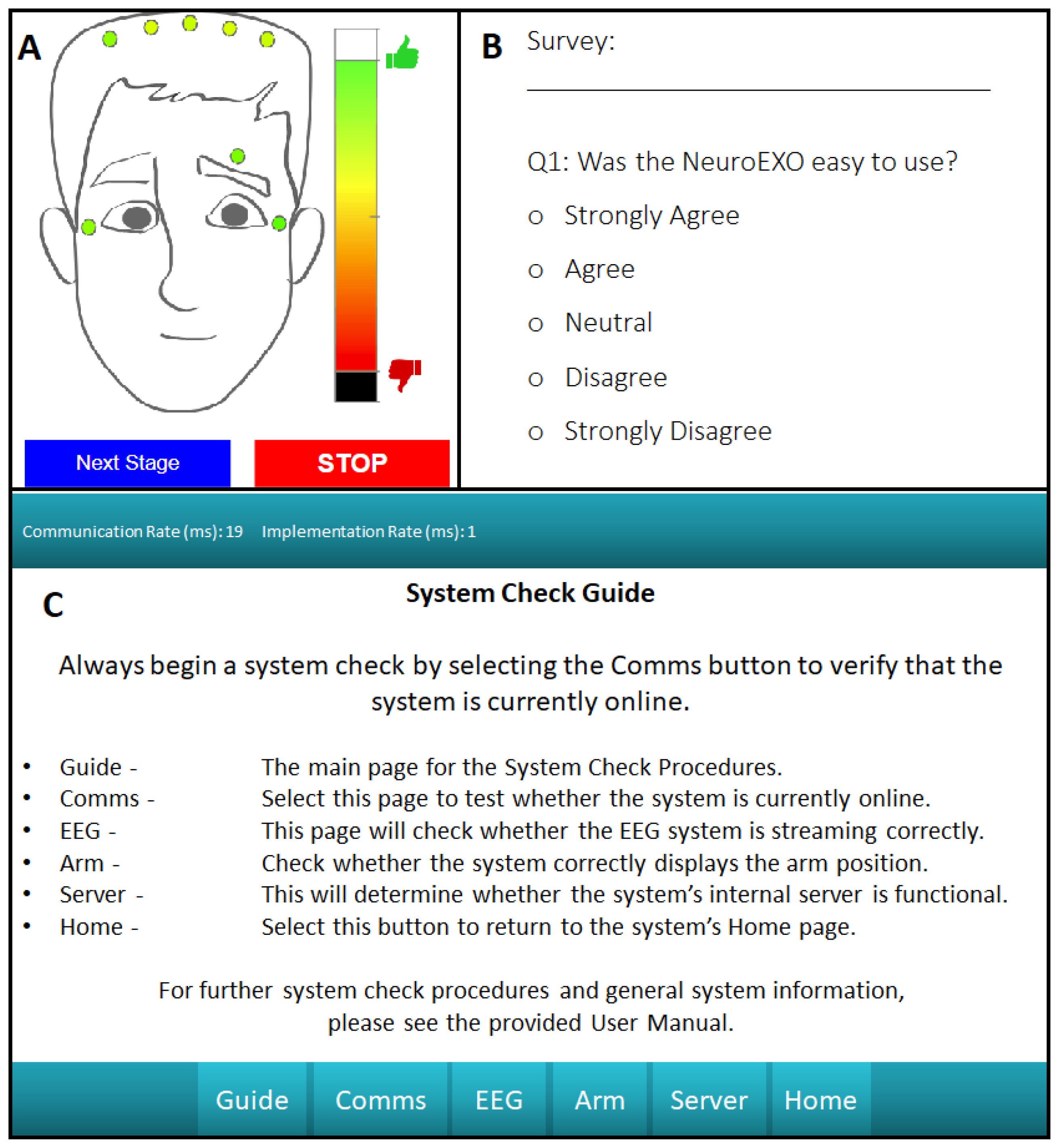
Impedance Check - Ensuring signal quality involves measuring and displaying impedance values for the user so that, for electrodes that show high impedance values, the user can adjust the electrodes accordingly. Real-time display of these impedance values is therefore an essential module for BCI systems. Here, the module is designed to set up the amplifier, interpolate at a constant sampling frequency, filter at the prescribed subband range (as designated by the ADS1299 documentation), and send the resulting impedance values to the user interface in real-time.
Figure 5A displays the user friendly interface for the system impedance check.
Model Calibration - For applications that rely on machine learning model predictions for the acquisition of a control signal, training data must first be collected to train the machine learning model. Following the impedance check of the example protocol, the user is asked to perform a calibration protocol consisting of one or more data acquisition sessions. This data is then used to train a machine learning model. Once calibration data is collected, the machine learning model, in this case a Support Vector Machine (SVM), is trained with an internally developed and tested machine learning library (including hyperparameter optimization and n-fold cross validation), which the user can initiate from the user interface. Once the SVM model is trained, the user is then able to proceed with the model testing stage. In addition to collecting EEG data for each testing trial, this module also collects protocol-specific characteristics, which can be analyzed later by a clinician or researcher to verify the progress of a user through a specific protocol.
Survey Collection - The proposed system includes a survey functionality that gives the user a way to provide feedback, which can be completed at any time. These results are stored onboard the processing unit for further analysis. This pop-up interface is presented in
Figure 5-B, which can be modified depending on the type of feedback desired for a particular application.
Debugging Interface - For ease of use, significant effort was made in developing a debugging user interface. The device’s debugging interface in
Figure 5-C includes mechanisms to check whether the internal LabVIEW script is running, whether the web server is correctly activated, a signal impedance check with a channel-selection mechanism, and a device communication check. This provides the user with a series of simple steps that can be performed without guidance to address potential system faults. The debugging home screen provides the user with easy to understand descriptions of each debugging page to make troubleshooting as painless as possible.
2.3. Testing Methodology
The following tests were performed at the University of Houston (UH) under a human subjects protocol approved by the Institutional Review Boards at UH (studies #3430 and #2515) and the University of Texas Health Science Center of Houston (study HSC-MS-20-1287). Nine neurologically intact adults (six male, three female) were recruited and underwent a series of usability tests to validate the headset design. An additional five neurologically intact adults (four males and one female) were recruited and underwent a series of tests for validation of the BCI functionality. As a proof-of-concept, one additional 66 years old male-participant with chronic stroke, with hemiparisis in his left body, participated in the validation of the system for home use. All recruited participants gave their written informed consent prior to testing. Descriptions and expected results for all tests can be found in
Table 2.
2.3.1. Headset Usability Validation
Rigorous usability testing was essential to validate the headset design. The testing focused on three key aspects: good fit to the targeted users in a range of different head sizes, easy and intuitive use by one hand only, and steady sensor contact to the user’s scalp.
2.3.2. Brain Computer Interface Validation
To evaluate the functionality of the BCI, a set of tests were performed that focused on the performance of the BCI in open-loop and closed-loop operations, real-time impedance collection, and eye movement and blink collection.
Table 2.
Testing Methodology
Table 2.
Testing Methodology
| Headset Usability |
|---|
| Test Name |
Description |
Target Specifications |
| Comb Electrode |
Validate comb electrode design across different hair types |
Comb electrode tips should reach the scalp through all hair types |
| System Comfort |
Assess comfort levels following use of the system |
Sensors should reach the scalp and face with little to no discomfort during use |
| One-Size-Fits-All |
Assess fit and comfort (questionnaire) |
Headset should comfortable fit participants from 5th % (female) to 95th % (male) head sizes |
| Intuitive Design |
Test headset donning/doffing and operation by users |
Participants should be able to use the headset by themselves |
| System Usability |
The System Usability Scale (SUS) [44] is employed to test the system usability |
The score for each participant should exceed the SUS threshold for a usable system. |
| Brain Computer Interface Validation |
| Test Name |
Description |
Target Specifications |
| Signal Quality |
Assess electrode and skin sensor impedances |
Impedance less than 100 kOhm |
| Eye Blink and Movement Artifacts |
Assess EOG measurements during eye movements |
EOG (eye blink) signal should be high amplitude and low frequency |
| EEG-EOG-IMU |
Visualize multi-modality data streams |
EEG-EOG-IMU rasterplot shows synchronized measurements |
| Open-loop Performance |
Assess EEG power modulations in delta and mu bands during a GO - NOGO task |
Relative delta-band (mu-band) power increases (decreases) from NOGO to GO |
| SVM Model Training |
Assess decoding accuracy for motor intent |
At least 80% model accuracy using 4-fold cross-validation |
| Closed-loop BCI Performance |
Evaluate trained SVM for online prediction of motor intent |
Presence of Readiness Potentials/slow MRCPs |
3. Results
3.1. Headset Usability Test Results
3.1.1. Comb Electrode Test
While the participant with long and thick hair felt higher pressure from the EEG sensors, most participants felt light pressure with little discomfort. The electrode bracket adapted to the varied head shapes while properly establishing adequate contact.
3.1.2. System Comfort Test
For the comfort test, the participants were provided with a questionnaire that asked to rate the system with four questions: “The headset moved during the study", “The headset induced the feeling of dents on your head", “The headset feels too big on your head" and "The headset feels too small in your head". The possible rating values were: “Strongly Agree", “Agree", “Neutral", “Disagree" and “Strongly Disagree". The results are shown in
Table 3. Two participants experienced reduced comfort due to the resulting dents in their scalp following two hours of use.
3.1.3. One-Size-Fits-All Test
When female participants whose head measurements matched the 5th percentile of female head sizes wore the headset, the headset was in its fully contracted state with a comfortable and secure fit. When repeating this test with a participant near to the 95th percentile male circumference, the headband’s vertical sizing mechanism expanded 0.75 in. on both sides to accommodate the longer distance between the top of the head and the ears. The two ear-hub components correctly extended to match the larger circumference so as to fit the back of the head properly.
3.1.4. Intuitive Design Test
During the testing process, a majority of the participants were able to figure out how to adjust the headset size in the three adjustment axes. Specifically, they learned to slide the headband up and down for a good fit and turn the dial under the back box to adjust the headset circumference. In the placement of EOG and reference sensors, the participants learned to rotate the sensor arms up and down to the proper position with a steady contact to their skin, both at the temple area and behind the ear. Most participants were able to complete the whole process with only one hand.
3.1.5. System Usability Scale Score
The System Usability Scale (SUS) [
44] was used to assess the usability of the system. This metric has been used previously in the assessment of usability for other BCI systems [
45,
46]. For the proposed system, the average SUS score among the five participants was 90.5, which is above the threshold for an acceptable system.
3.2. Brain Computer Interface Test Results
In this section, we report the results from the signal quality, detection of eye movements and blinks, model training, and open-loop and closed-loop BCI assessments.
3.2.1. Signal Quality Test
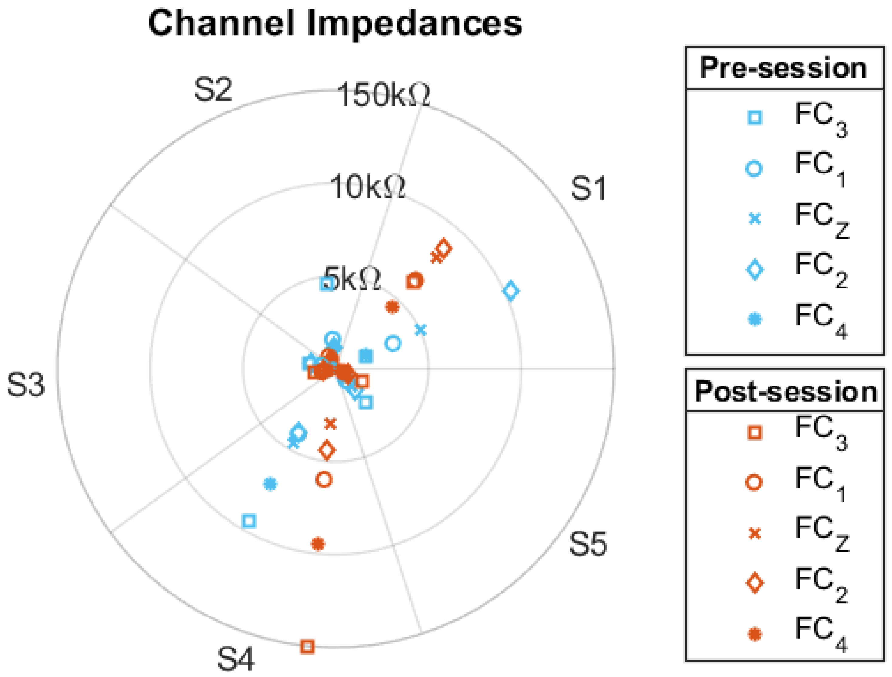
The impedance values from all electrodes were collected before and after the open-loop BCI test. The beginning and final impedance values for each electrode are presented in
Figure 6. For all but two impedance measurements, the electrode impedance values remained under 100 k
.
3.2.2. Eye Blink and Movement Artifacts
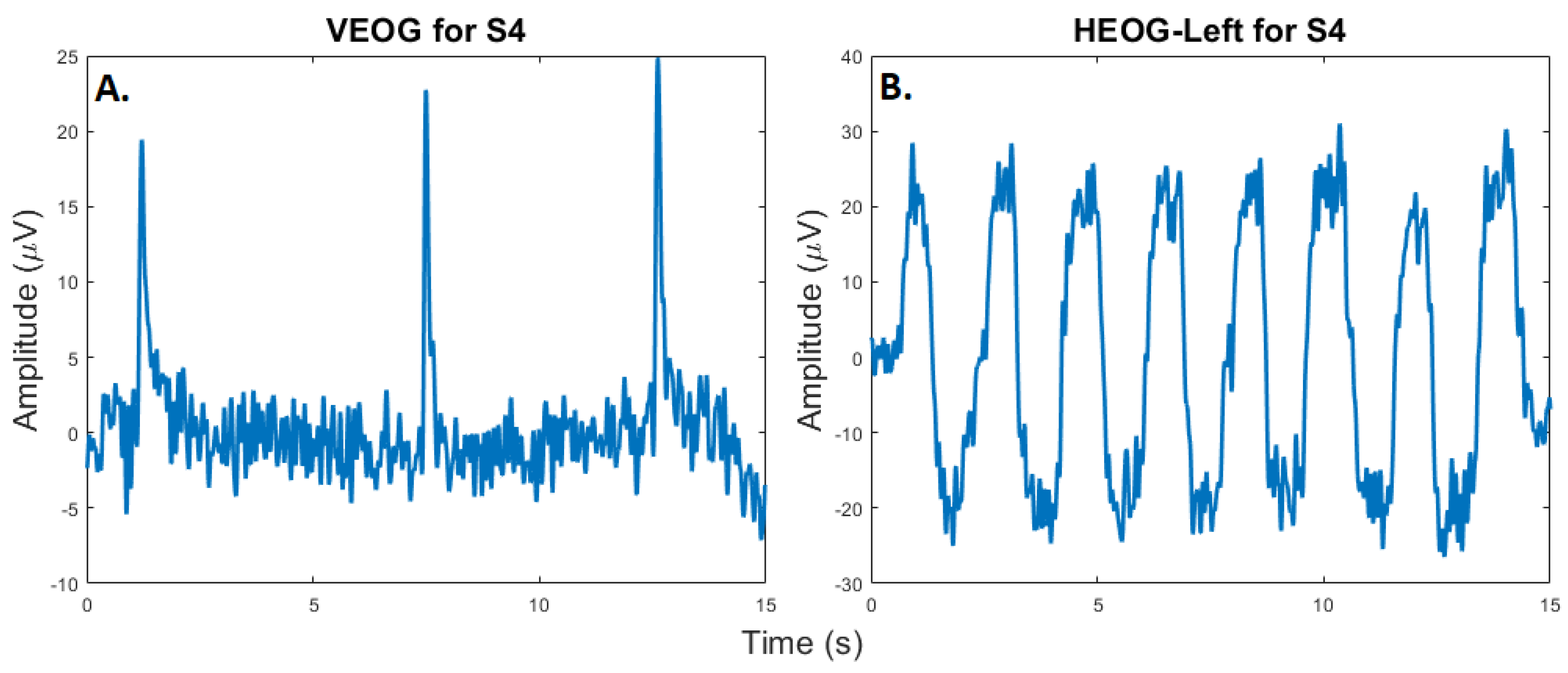
One of the most well-studied physiological artifacts contaminating EEG is due to eye blinks. In addition to the potential removal of EOG from EEG, the collection of EOG can also be used as a control signal in BCI systems. To demonstrate that the proposed system can collect EOG information for either the removal of EOG contamination or as a control signal, participants were asked to blink repeatedly and to move their eyes up horizontally from the center position. Examples of this EOG collection, which was collected at 80 Hz, are presented in
Figure 7.
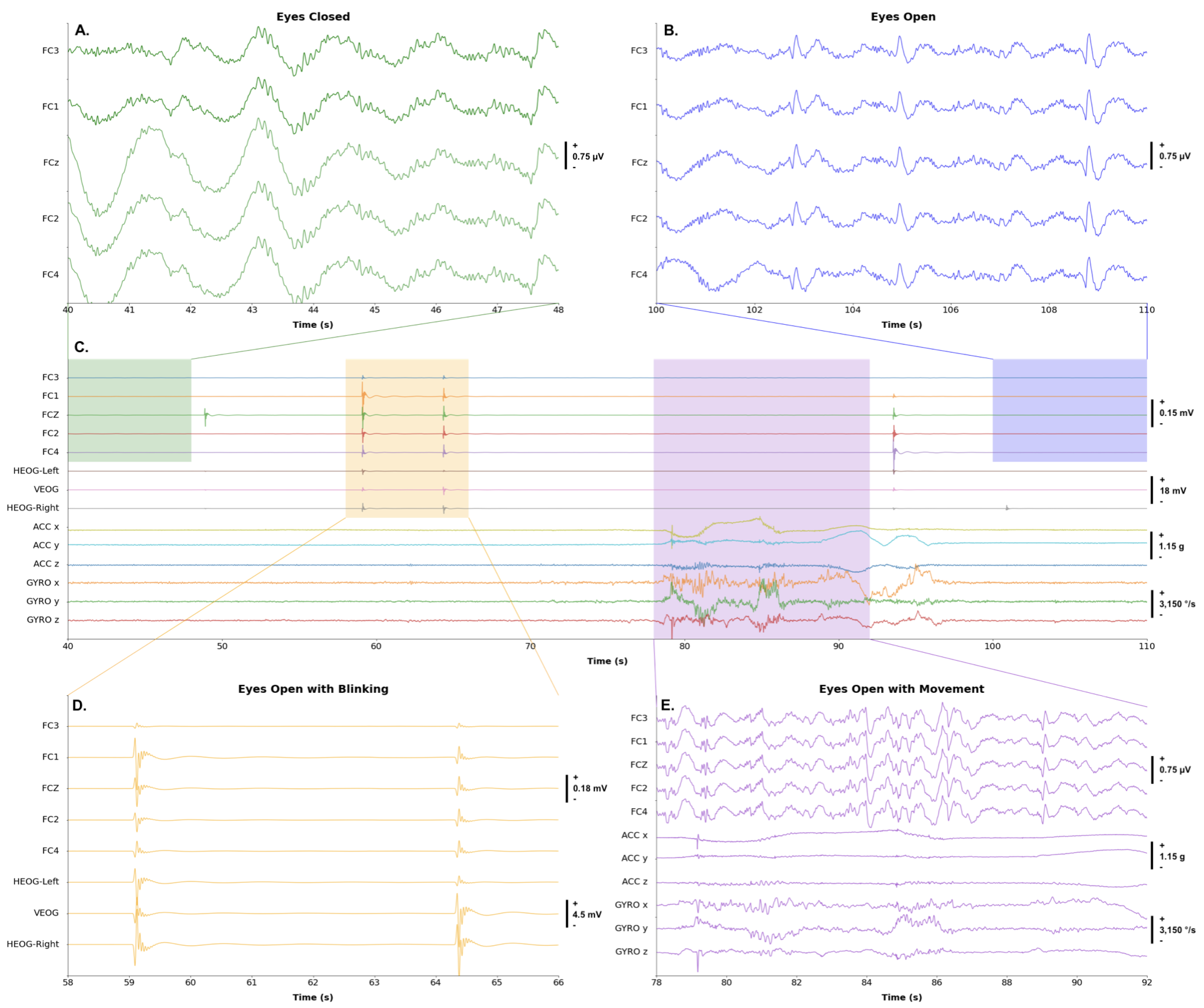
3.2.3. Synchronized EEG-EOG-IMU
Additional known artifacts that contaminate EEG signals are due to motion. The collection of IMU data from the head of the participant can be used to remove or characterize motion artifacts. To illustrate that the proposed BCI system can collect IMU data synchronized with EOG and EEG data, one participant was asked to maintain eyes closed, open eyes, blink two times, and move their head in different directions. An example of the synchronized IMU, EEG, and EOG signal, collected at
, is presented in
Figure 8. A band-pass filter from
to
was applied to the signal; however, no de-noising methods were used.
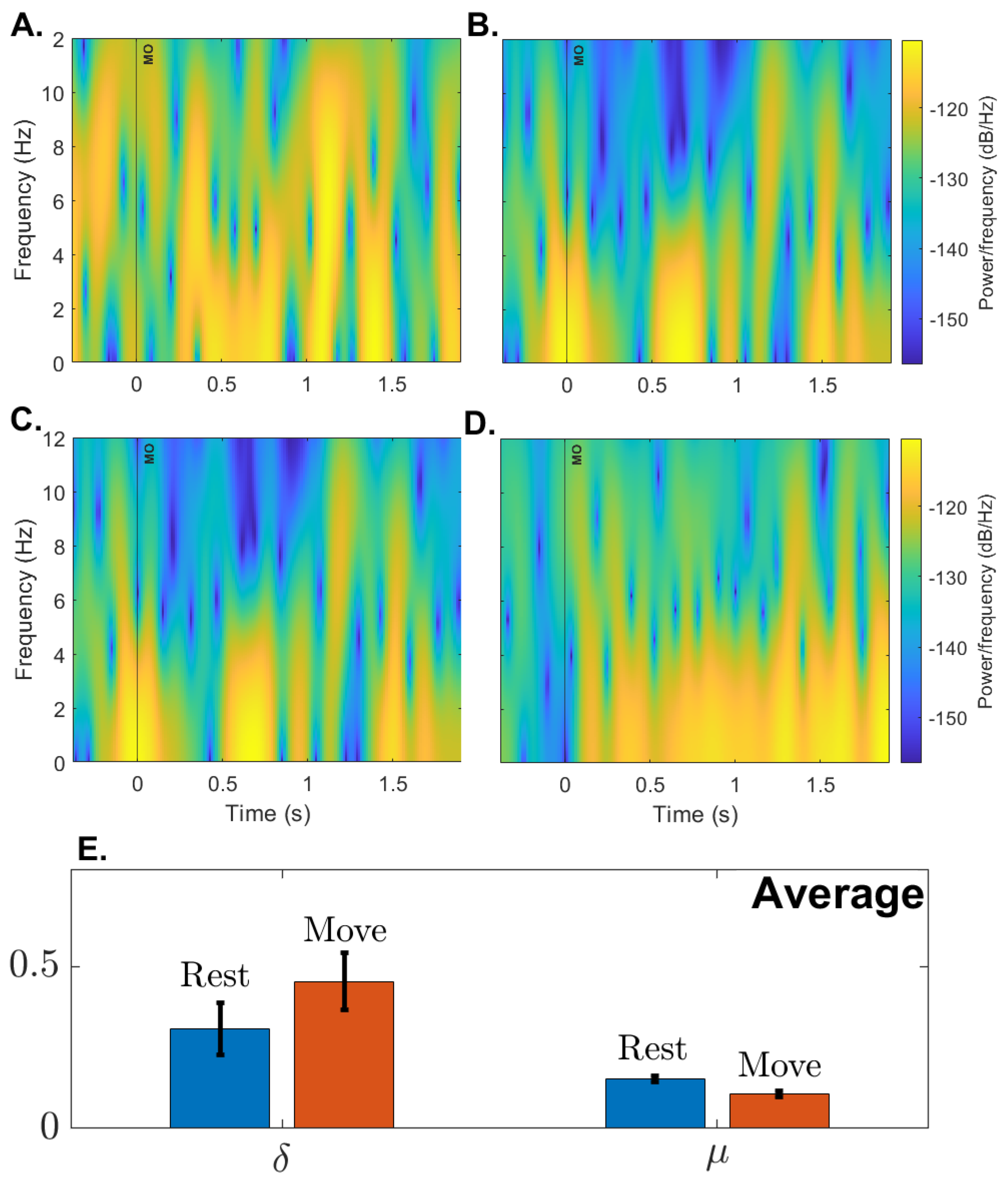
3.2.4. Open-loop Performance
To assess the spectral characteristics of EEG, four participants underwent two blocks of 21 trials of a simple GO - NOGO paradigm. In this paradigm, the system’s user interface first asked the participant to fix their attention on a cross (NOGO) for five seconds. The interface then presented a circle and indicated to the user to move their arm from a horizontal to a vertical position (GO). The expected spectral trends for a paradigm of this nature [
47,
48,
49] would be that, when moving from NOGO to GO, the relative power in the
band should increase while the relative power in the
band should decrease.
Figure 9 provides support that the relative power in these two bands for all participants follow our expectations. The paired t-tests with Rest/Move factor for all electrodes, except
were significant (p<0.0001)
for
, and
for
.
3.2.5. Machine Learning Model Cross-Validation Test Results
To evaluate the neural decoding accuracy of the Support Vector Machine (SVM) model, the experimental protocol described in [
9,
30] was used.
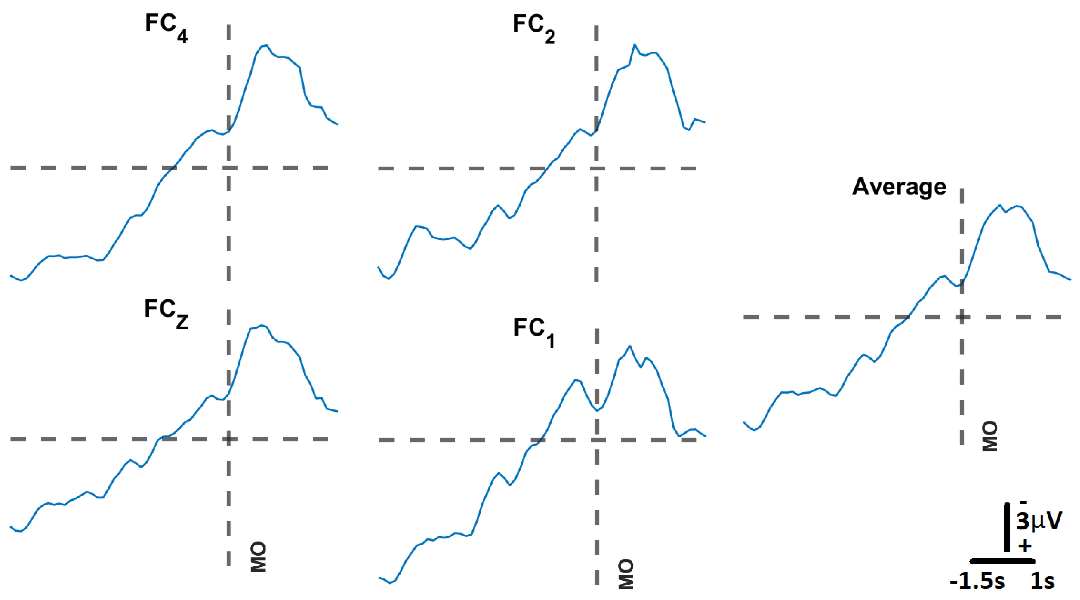
Figure 10 presents the Movement-Related Cortical Potentials (MRCPs) recorded through the experimental protocol, which were then used to train the SVM neural decoding model.
Table 4 presents the decoding accuracies on S005’s data for a model trained with the hyperparameters displayed in
Table 4, where the Rejection Rate refers to the amount of outliers on the data to be rejected for the training and validation of the model. All models were trained with 4-fold cross-validation.
3.2.6. Closed-Loop Performance
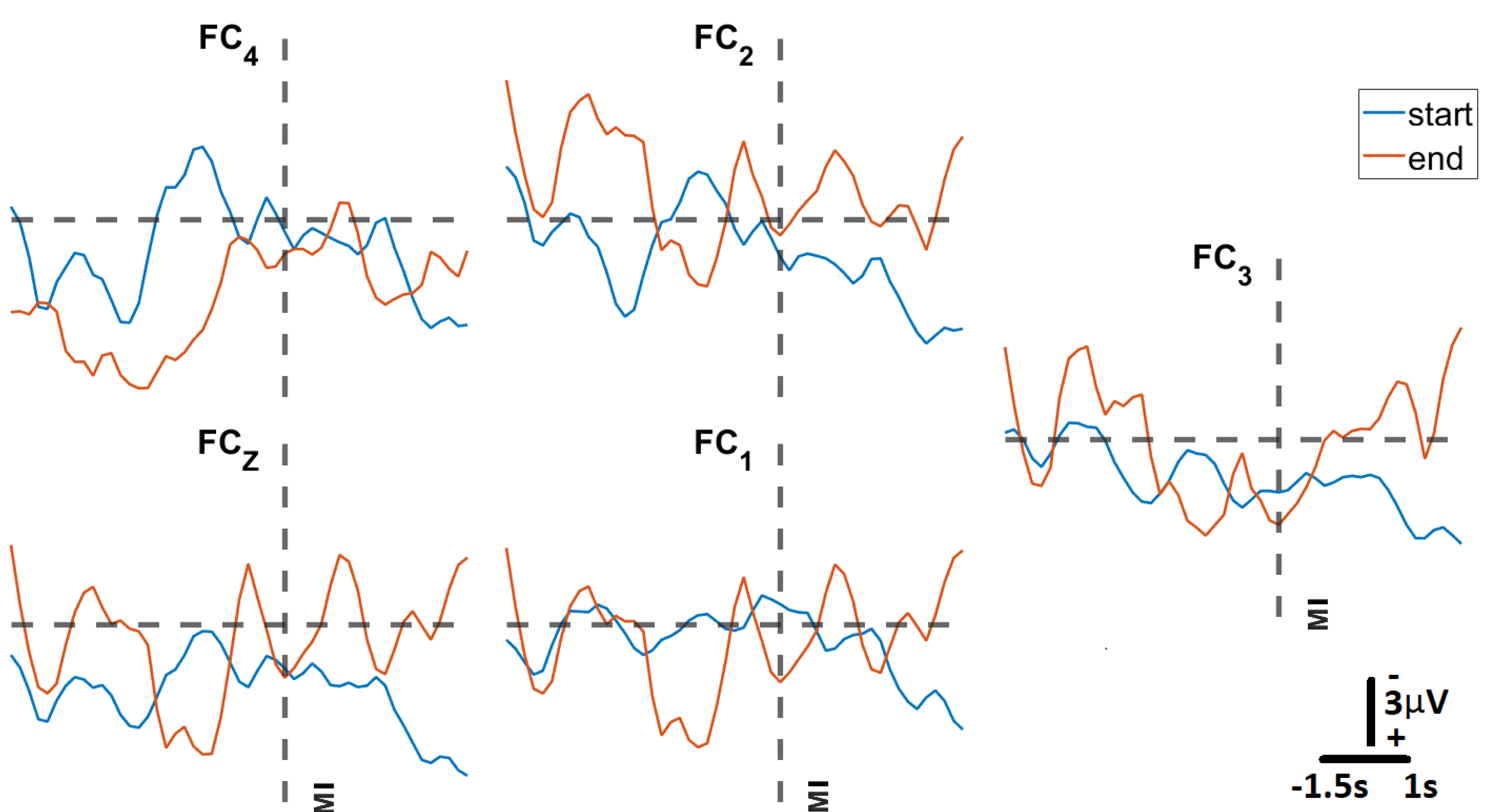
To assess whether the trained SVM could correctly predict motor intent during closed-loop BCI operation, the model was deployed during a series of GO (Move) - NOGO (Fixate) trials at the participant’s home. For this test we considered two sessions per day, with each session consisting of three blocks of 20 trials over a period of six weeks and an average of six sessions per week. In
Figure 11, we present signals classified by the trained model as representative of motor intent, where “Movement Intent" indicates when the model detected the motor intent. Each of these signals is the average of the 20 trials from the first block at the start of the protocol (in blue), and the last block at the end of the protocol (in orange). We can see here how the MRCP evolves across the six weeks of at-home BCI therapy for four of the five EEG Channels (
,
,
,
). This evolution is not evident in the case of
, which is the result of the relatively poor contact between that channel and the scalp of the participant (impedance values of
).
4. Discussion and Conclusions
The design of a custom EEG BCI headset with onboard processing capabilities is a complex systems engineering task that requires the consideration of a number of factors. Here, we have developed a minimal viable solution to this design task that is low-cost, portable, wireless, easy to use and with high interoperability. To ensure a comfortable user experience, the proposed solution has a form factor that provides a one-size-fits-all approach, includes a user-friendly graphical interface, and, as reliability can determine whether the user continues using the system. Additionally, the system has adaptive signal de-noising and decoding capabilities built into the onboard processing board, making the system fully contained within the headset, a feature not currently found in off-the-shelf commercially available systems. All components of the system have been extensively bench-tested and also validated with healthy adults, including an individual with chronic stroke.
In the development of the proposed system, the design team was made painfully aware of the cascading nature of single design decisions. Future developers would benefit from understanding how certain decisions made early in the development can significantly limit the available options for other hardware and software components. For the current system, the most influential design choice was in the selection of LabVIEW as the back-end coding language. While LabVIEW has a large number of well-tested libraries available, many of these libraries require a processing board developed by National Instruments. Due to the cost of those boards, the selection of the processing board was limited by whether the board was capable of using an open-source user-built LabVIEW library, which is not as well-tested as the libraries developed by National Instruments. Many of the challenges faced in the development of the proposed system were due to incompatibilities between LabVIEW and the low-cost processing board. Future projects would benefit from a careful selection of high-level system components (such as back-end language, port selections, wireless protocol, etc.) to avoid such challenges. In this regard, and to show flexibility of the proposed system, we have recently programmed the board in C++ and achieved an open-loop sampling rate of .
In conclusion, the proposed system should provide an open test bed for developing low-cost and portable yet effective custom EEG systems with wireless capabilities, which will help expand the potential user base for commercial neuroengineering, BCI, and IoT applications and increase the feasibility for academic research and workforce development.
Author Contributions
A. Craik: Methodology, Software, Validation, Writing - Original Draft. J. Gonzalez-Espana: Electronic Circuit Design, Firmware, Power System, Bench Testing, Writing - review & editing. A. Alamir: Methodology, Graphical User Interface, Validation, Writing - review & editing. D. Edqulilang: 3D Model Design and Prototyping, Writing - review & editing. J. Feng: Methodology, 3D Model Design and Prototyping, Supervision, Writing - review & editing. J. Contreras-Vidal: Conceptualization, Funding acquisition, Methodology, Resources, Supervision, Visualization, Analysis Strategy, and Writing - review & editing. All authors have reviewed and approved the manuscript.
Acknowledgements
This work was supported by National Science Foundation PFI Award # 1827769 and Research Experiences for Undergraduates (NSF REU Site) Award # 1650536.
Appendix A
Appendix A.1. Inertial Measurement Unit Characteristics
Table A1.
Inertial Measurement Unit: ICM-20948 [
50]
Table A1.
Inertial Measurement Unit: ICM-20948 [
50]
| Metric |
ICM-20948 |
| ADC (bits) |
16 |
| Dynamic Range (dps) |
250-2000 |
| Zero offset error(dps) (at 250dps) |
|
| Zero-g Offset (mg) |
|
| Power Acc+Mgn (mW) |
0.580 |
| Power Gyro (mW) |
4.43 |
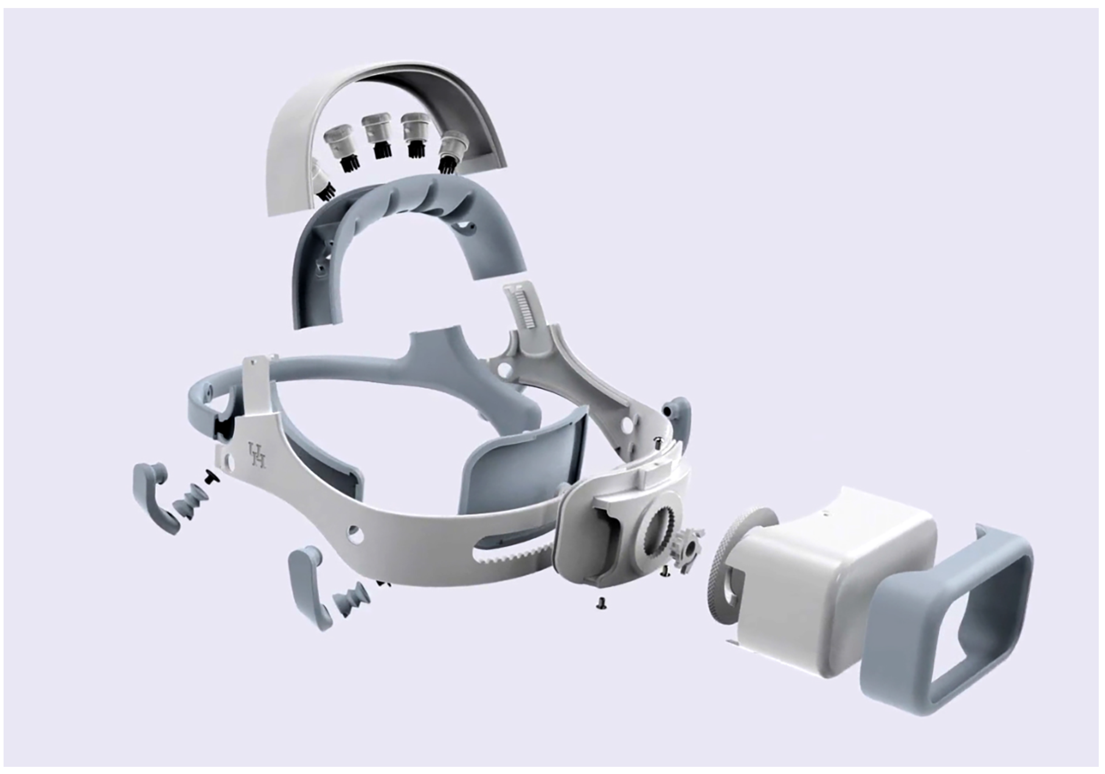
Appendix A.2. Exploded Headset Image
Figure A1.
The headset exploded view showing all components.
Figure A1.
The headset exploded view showing all components.
References
- A. Craik, Y. He, and J. L. Contreras-Vidal, “Deep learning for electroencephalogram (eeg) classification tasks: A review,” Journal of neural engineering, vol. 16, no. 3, p. 031001, 2019. [CrossRef]
- A. G. Steele, S. Parekh, H. F. Azgomi, M. B. Ahmadi, A. Craik, S. Pati, J. T. Francis, J. L. Contreras-Vidal, and R. T. Faghih, “A mixed filtering approach for real-time seizure state tracking using multi-channel electroencephalography data,” IEEE Transactions on Neural Systems and Rehabilitation Engineering, vol. 29, pp. 2037–2045, 2021. [CrossRef]
- M. B. Ahmadi, A. Craik, H. F. Azgomi, J. T. Francis, J. L. Contreras-Vidal, and R. T. Faghih, “Real-time seizure state tracking using two channels: A mixed-filter approach,” in 2019 53rd Asilomar Conference on Signals, Systems, and Computers. IEEE, 2019, pp. 2033–2039.
- K. A. I. Aboalayon, M. Faezipour, W. S. Almuhammadi, and S. Moslehpour, “Sleep stage classification using eeg signal analysis: A comprehensive survey and new investigation,” Entropy, vol. 18, no. 9, p. 272, 2016. [CrossRef]
- Y. Zhou, S. Huang, Z. Xu, P. Wang, X. Wu, and D. Zhang, “Cognitive workload recognition using eeg signals and machine learning: A review,” IEEE Transactions on Cognitive and Developmental Systems, 2021. [CrossRef]
- A. Craik, A. Kilicarslan, and J. L. Contreras-Vidal, “Classification and transfer learning of eeg during a kinesthetic motor imagery task using deep convolutional neural networks,” in 2019 41st Annual International Conference of the IEEE Engineering in Medicine and Biology Society (EMBC). IEEE, 2019, pp. 3046–3049.
- L. Ferrero, V. Quiles, M. Ortiz, E. Iáñez, A. Navarro-Arcas, J. Flores-Yepes, J. Contreras-Vidal, and J. Azorín, “Comparison of different brain–computer interfaces to assess motor imagery using a lower-limb exoskeleton,” in Converging Clinical and Engineering Research on Neurorehabilitation IV: Proceedings of the 5th International Conference on Neurorehabilitation (ICNR2020), October 13–16, 2020. Springer, 2022, pp. 53–58.
- D. T. Bundy, L. Souders, K. Baranyai, L. Leonard, G. Schalk, R. Coker, D. W. Moran, T. Huskey, and E. C. Leuthardt, “Contralesional brain–computer interface control of a powered exoskeleton for motor recovery in chronic stroke survivors,” Stroke, vol. 48, no. 7, pp. 1908–1915, 2017. [CrossRef]
- N. A. Bhagat, N. Yozbatiran, J. L. Sullivan, R. Paranjape, C. Losey, Z. Hernandez, Z. Keser, R. Grossman, G. Francisco, M. K. O’Malley et al., “A clinical trial to study changes in neural activity and motor recovery following brain-machine interface enabled robot-assisted stroke rehabilitation,” medRxiv, 2020.
- A. Nijholt, “Multi-modal and multi-brain-computer interfaces: A review,” in 2015 10th International Conference on Information, Communications and Signal Processing (ICICS). IEEE, 2015, pp. 1–5.
- A. Hekmatmanesh, P. H. Nardelli, and H. Handroos, “Review of the state-of-the-art of brain-controlled vehicles,” IEEE Access, 2021. [CrossRef]
- P. K. Shukla and R. K. Chaurasiya, “A review on classification methods used in eeg-based home control systems,” in 2018 3rd International Conference and Workshops on Recent Advances and Innovations in Engineering (ICRAIE). IEEE, 2018, pp. 1–5.
- R. Zhang, “Virtual reality games based on brain computer interface,” in 2020 International Conference on Intelligent Computing and Human-Computer Interaction (ICHCI). IEEE, 2020, pp. 227–230.
- B. Kerous and F. Liarokapis, “Brain-computer interfaces-a survey on interactive virtual environments,” in 2016 8th international conference on games and virtual worlds for serious applications (vs-games). IEEE, 2016, pp. 1–4.
- A. Craik, A. Kilicarslan, and J. L. Contreras-Vidal, “A translational roadmap for a brain-machine-interface (bmi) system for rehabilitation,” in 2019 IEEE International Conference on Systems, Man and Cybernetics (SMC). IEEE, 2019, pp. 3613–3618.
- Y. He, D. Eguren, J. M. Azorín, R. G. Grossman, T. P. Luu, and J. L. Contreras-Vidal, “Brain–machine interfaces for controlling lower-limb powered robotic systems,” Journal of neural engineering, vol. 15, no. 2, p. 021004, 2018. [CrossRef]
- “Open source tools for neuroscience.” [Online]. Available: https://openbci.com/.
- “Meditation made easy,” Jan 2023. [Online]. Available: https://choosemuse.com/.
- G. Niso, E. Romero, J. T. Moreau, A. Araujo, and L. R. Krol, “Wireless eeg: An survey of systems and studies,” NeuroImage, vol. 269, p. 119774, 2022. [CrossRef]
- T. Feng, D. Kuhn, K. Ball, S. Kerick, and K. McDowell, “Evaluation of a prototype low-cost, modular, wireless electroencephalography (eeg) headset design for widespread application,” Army Research Lab Aberdeen Proving Ground United Kingdom, Tech. Rep., 2016.
- W. D. Hairston, K. W. Whitaker, A. J. Ries, J. M. Vettel, J. C. Bradford, S. E. Kerick, and K. McDowell, “Usability of four commercially-oriented eeg systems,” Journal of neural engineering, vol. 11, no. 4, p. 046018, 2014. [CrossRef]
- S. Verwulgen, D. Lacko, J. Vleugels, K. Vaes, F. Danckaers, G. De Bruyne, and T. Huysmans, “A new data structure and workflow for using 3d anthropometry in the design of wearable products,” International Journal of Industrial Ergonomics, vol. 64, pp. 108–117, 2018. [CrossRef]
- G. Li, S. Wang, and Y. Y. Duan, “Towards gel-free electrodes: A systematic study of electrode-skin impedance,” Sensors and Actuators B: Chemical, vol. 241, pp. 1244–1255, 2017. [CrossRef]
- S. Pheasant and C. M. Haslegrave, Bodyspace: Anthropometry, ergonomics and the design of work. CRC press, 2018.
- D. Lacko, J. Vleugels, E. Fransen, T. Huysmans, G. De Bruyne, M. M. Van Hulle, J. Sijbers, and S. Verwulgen, “Ergonomic design of an eeg headset using 3d anthropometry,” Applied ergonomics, vol. 58, pp. 128–136, 2017. [CrossRef]
- T. Ellena, A. Subic, H. Mustafa, and T. Y. Pang, “The helmet fit index–an intelligent tool for fit assessment and design customisation,” Applied ergonomics, vol. 55, pp. 194–207, 2016. [CrossRef]
- A. K. Karlson, B. B. Bederson, and J. Contreras-Vidal, “Understanding single-handed mobile device interaction,” Handbook of research on user interface design and evaluation for mobile technology, vol. 1, pp. 86–101, 2006.
- D. C. Yates and E. Rodriguez-Villegas, “A key power trade-off in wireless eeg headset design,” in 2007 3rd International IEEE/EMBS Conference on Neural Engineering. IEEE, 2007, pp. 453–456.
- J. N. Acharya, A. J. Hani, P. Thirumala, and T. N. Tsuchida, “American clinical neurophysiology society guideline 3: A proposal for standard montages to be used in clinical eeg,” The Neurodiagnostic Journal, vol. 56, no. 4, pp. 253–260, 2016. [CrossRef]
- N. A. Bhagat, A. Venkatakrishnan, B. Abibullaev, E. J. Artz, N. Yozbatiran, A. A. Blank, J. French, C. Karmonik, R. G. Grossman, M. K. O’Malley et al., “Design and optimization of an eeg-based brain machine interface (bmi) to an upper-limb exoskeleton for stroke survivors,” Frontiers in neuroscience, vol. 10, p. 122, 2016.
- Y.-H. Chen, M. O. de Beeck, L. Vanderheyden, V. Mihajlovic, B. Grundlehner, and C. Van Hoof, “Comb-shaped polymer-based dry electrodes for eeg/ecg measurements with high user comfort,” in 2013 35th Annual International Conference of the IEEE Engineering in Medicine and Biology Society (EMBC). Ieee, 2013, pp. 551–554.
- C. C. Gordon, C. L. Blackwell, B. Bradtmiller, J. L. Parham, P. Barrientos, S. P. Paquette, B. D. Corner, J. M. Carson, J. C. Venezia, B. M. Rockwell et al., “2012 anthropometric survey of us army personnel: Methods and summary statistics,” Army Natick Soldier Research Development and Engineering Center MA, Tech. Rep., 2014.
- T. Kawana, Y. Yoshida, Y. Kudo, C. Iwatani, and N. Miki, “Design and characterization of an eeg-hat for reliable eeg measurements,” Micromachines, vol. 11, no. 7, p. 635, 2020. [CrossRef]
- N. Gorman, A. Louw, A. Craik, J. Gonzalez, J. Feng, and J. L. Contreras-Vidal, “Design principles for mobile brain-body imaging devices with optimized ergonomics,” in International Conference on Applied Human Factors and Ergonomics. Springer, 2021, pp. 3–10.
- “Meet beagle™: Open source computing.” [Online]. Available: https://beagleboard.org/.
- “Linx labview makerhub.” [Online]. Available: https://www.labviewmakerhub.com/doku.php?id=learn:start.
- M. Nuwer, G. Comi, R. Emerson, A. Fuglsang-Frederiksen, J. Guerit, H. Hinrichs, A. Ikeda, F. Luccas, and P. Rappelsburger, “IFCN standards for digital recording of clinical EEG,” Electroencephalography and Clinical Neurophysiology, vol. 106, no. 3, pp. 259–261, MAR 1998. [CrossRef]
- TI, ADS1299 Analog-to-Digital Converter for EEG and Biopotential Measurements, Texas Instruments, 1 2017, rev. 2.
- Louis, Polymer Lithium-ion Battery Product Specification, AA Portable Power Corp, 1 2010, rev. 1.
- O. S. LLC, OSD3358 Application Guide, Octavo Systems LLC, 4 2017, rev. 5.
- A. Kilicarslan, R. G. Grossman, and J. L. Contreras-Vidal, “A robust adaptive denoising framework for real-time artifact removal in scalp eeg measurements,” Journal of neural engineering, vol. 13, no. 2, p. 026013, 2016. [CrossRef]
- B. Jenny and N. V. Kelso, “Color design for the color vision impaired,” Cartographic perspectives, no. 58, pp. 61–67, 2007. [CrossRef]
- J. Allan, “Accessibility requirements for people with low vision,” Mar 2016. [Online]. Available: https://www.w3.org/TR/low-vision-needs/.
- J. Brooke, "SUS-A quick and dirty usability scale." Usability evaluation in industry. CRC Press, June 1996, iSBN: 9780748404605. [Online]. Available: https://www.crcpress.com/product/isbn/9780748404605.
- T. O. Zander, L. M. Andreessen, A. Berg, M. Bleuel, J. Pawlitzki, L. Zawallich, L. R. Krol, and K. Gramann, “Evaluation of a dry eeg system for application of passive brain-computer interfaces in autonomous driving,” Frontiers in Human Neuroscience, vol. 11, 2017. [Online]. Available: https://www.frontiersin.org/articles/10.3389/fnhum.2017.00078. [CrossRef]
- M. Duvinage, T. Castermans, M. Petieau, K. Seetharaman, T. Hoellinger, G. Cheron, and T. Dutoit, “A subjective assessment of a p300 bci system for lower-limb rehabilitation purposes,” in 2012 Annual International Conference of the IEEE Engineering in Medicine and Biology Society, 2012, pp. 3845–3849.
- W. N. Kuhlman, “Functional topography of the human mu rhythm,” Electroencephalography and Clinical Neurophysiology, vol. 44, no. 1, pp. 83–93, 1978. [Online]. Available: https://www.sciencedirect.com/science/article/pii/0013469478901074.
- V. Müller and A. P. Anokhin, “Neural synchrony during response production and inhibition,” PLoS One, vol. 7, no. 6, p. e38931, 2012. [CrossRef]
- M. Schoppenhorst, F. Brauer, G. Freund, and S. Kubicki, “The significance of coherence estimates in determining central alpha and mu activities,” Electroencephalography and Clinical Neurophysiology, vol. 48, no. 1, pp. 25–33, 1980. [Online]. Available: https://www.sciencedirect.com/science/article/pii/0013469480900401. [CrossRef]
- TDK, ICM-20948 World’s Lowest Power 9-Axis MEMS MotionTracking™ Device, TDK InvenSense, 9 2021, rev. 1.5.
Figure 1.
Proposed criteria that need to be considered when designing closed-loop brain computer interface (BCI) systems to maximize translation impact for the end-user.
Figure 1.
Proposed criteria that need to be considered when designing closed-loop brain computer interface (BCI) systems to maximize translation impact for the end-user.
Figure 2.
A custom EEG-based BCI headset, with wireless tablet-based graphical user interface (GUI), and an IOT-enabled powered upper-limb exoskeleton robotic device deployed in a neurorehabilitation application.
Figure 2.
A custom EEG-based BCI headset, with wireless tablet-based graphical user interface (GUI), and an IOT-enabled powered upper-limb exoskeleton robotic device deployed in a neurorehabilitation application.
Figure 4.
Block Diagram of the EEG Amplifier Board.
Figure 4.
Block Diagram of the EEG Amplifier Board.
Figure 5.
A: User friendly interface that presents real-time impedance measurements. B: Easy-to-use survey functionality for direct user feedback. C: Debugging interface that can be used for troubleshooting of the system by the user.
Figure 5.
A: User friendly interface that presents real-time impedance measurements. B: Easy-to-use survey functionality for direct user feedback. C: Debugging interface that can be used for troubleshooting of the system by the user.
Figure 6.
Impedance: Impedance values from the open-loop sessions of five different participants. The values were taken before (blue) and after (orange) the session. The values are in k.
Figure 6.
Impedance: Impedance values from the open-loop sessions of five different participants. The values were taken before (blue) and after (orange) the session. The values are in k.
Figure 7.
A. Eye blink: A participant was instructed to blink three times during a session. In this plot we can see the signal detected by the vertical EOG sensor of the proposed headset. B. Eye Movement: A participant was instructed to move their eyes left-to-right and right-to-left over a period of 15 seconds. In this plot, the resultant signal detected by the Horizontal Left EOG sensor of the proposed headset is presented.
Figure 8.
A. Eyes Closed: A participant was instructed to maintain eyes closed for a period during the session. B. Eyes Opened: A participant was instructed to open eyes. C. Complete Session: During the two-minute session, the participant was asked to do several sequential tasks. D. Blinking: A participant was instructed to blink two times. The plot shows the effects of high amplitude EOG artifacts on raw EEG signals. E. The effect of motion on raw EEG: A participant was instructed to move their head towards the front, back, left, and right.
Figure 9.
Spectrogram and Relative power: A-D. Plots show the average spectrogram for participants S1-S4 from 0.5S before Movement Onset (MO) to 2s after MO. E. shows average relative power in the , frequency bands among participants. The average is based on two blocks with twenty trials each.
Figure 9.
Spectrogram and Relative power: A-D. Plots show the average spectrogram for participants S1-S4 from 0.5S before Movement Onset (MO) to 2s after MO. E. shows average relative power in the , frequency bands among participants. The average is based on two blocks with twenty trials each.
Figure 10.
Movement Related Cortical Potential, MRCP:Following the protocol proposed by [
9,
30] we obtained the MRCP for participant S005. For each channel, the MRCPs were obtained from averaging 20 trials. The spatial average of those averages is the plot labeled “Average”. Channel
was excluded due to its high impedance value for this participant. The vertical broken line represents the Movement Onset (MO).
Figure 11.
Average MRCP amplitudes at start and end of therapy: The subfigures show MRCPs across each of the five EEG electrodes recorded for participant S005 at start (block 1) and end (block 105) after six weeks of the at-home BCI therapy. Each MRCP is the result of averaging each of the 20 trials in each block. The vertical dotted line represents the moment Movement Intent (MI) was detected by the SVM machine learning model.
Table 1.
Technical specifications for the proposed device.
Table 1.
Technical specifications for the proposed device.
| Headset Specifications |
|---|
| Circumference Adjustment Range (in.) |
20.60" - 24.10" |
| Head Breadth Adjustment Range (in.) |
5.45" - 6.53" |
| Head Length Adjustment Range (in.) |
6.79" - 8.42" |
| EEG Electrode Locations |
FC3,
FC1, FCz, FC2, FC4 |
| EEG Electrode Type |
Dry Comb Electrodes |
| EOG Electrode Locations |
Both Temples, Above Left Eye |
| Reference Electrode Locations |
Mastoids |
| EOG and Reference Electrode Type |
Dry Flat Electrodes |
| Amplifier Specifications |
| Number of Channels |
8 |
| SNR (dB) |
121 |
| Input Noise () |
1.39 |
| CMRR (dB) |
110 |
| ADC Resolution (bits) |
24 |
| Impedance (M) |
1000 |
| Maximum Sampling Rate (Hz) |
500 |
| Bandwidth (Hz) |
DC-131 |
| Input range (mV) |
± 104 |
| Resolution (V) |
0.012 |
| Inertial Measurement Unit Specifications |
| ADC |
16 |
| Gyro Full-Scale Range (dps) |
250-2000 |
| Acc Full-Scale Range (g) |
2-16 |
| Zero offset error (for 250dps) |
5 |
| Zero-g Offset(mg) |
|
| Power Consumption Acc+Mgn (mW) |
0.580 |
| Power Consumption Gyro (mW) |
4.43 |
| Brain Computer Interface Specifications |
| Processor Speed (GHz) |
1 |
| Processor Memory (MB) |
512 |
| Processor Storage (GB) |
4 |
| Open-Loop Sampling Frequency (Hz) |
80 |
| Closed-Loop Sampling Frequency (Hz) |
40 |
| Communication |
802.11 b/g/n WiFi |
| Backend Coding Language |
LabVIEW |
| Frontend Coding Language |
JS, CSS, HTML |
| Machine Learning Capability |
Support Vector Machine |
| De-noising Capabilities |
Low and High Pass Filters, Adaptive Noise Cancellation |
| Battery Capacity (kWh) |
2.96 |
Table 3.
Comfort Score: 1: “Strongly Agree" to 5:“Strongly Disagree"
Table 3.
Comfort Score: 1: “Strongly Agree" to 5:“Strongly Disagree"
| Participant # |
“Moving" |
“Dents" |
“Too big" |
“Too Small" |
| S1 |
5 |
5 |
5 |
5 |
| S2 |
5 |
2 |
5 |
5 |
| S3 |
4 |
2 |
3 |
3 |
| S4 |
4 |
2 |
5 |
5 |
| S5 |
5 |
3 |
5 |
5 |
| Mean |
4.6 |
2.8 |
4.6 |
4.6 |
| SD |
0.548 |
1.304 |
0.894 |
0.894 |
Table 4.
Hyperparameter Optimization: closed-loop model hyperparameter optimization using 4-fold cross-validation on participant S005’s data.
Table 4.
Hyperparameter Optimization: closed-loop model hyperparameter optimization using 4-fold cross-validation on participant S005’s data.
| Hyperparameter |
|
| Rejection Rate |
Channels not used |
Accuracy |
| 0 |
- |
85.47% |
| 0.1 |
- |
97.4% |
| 0.2 |
- |
100% |
| 0.3 |
- |
100% |
| 0 |
FC3 |
96.34% |
| 0.1 |
FC3 |
98.63% |
| 0.2 |
FC3 |
99.25% |
| 0.3 |
FC3 |
99.14% |
|
Disclaimer/Publisher’s Note: The statements, opinions and data contained in all publications are solely those of the individual author(s) and contributor(s) and not of MDPI and/or the editor(s). MDPI and/or the editor(s) disclaim responsibility for any injury to people or property resulting from any ideas, methods, instructions or products referred to in the content. |
© 2023 by the authors. Licensee MDPI, Basel, Switzerland. This article is an open access article distributed under the terms and conditions of the Creative Commons Attribution (CC BY) license (http://creativecommons.org/licenses/by/4.0/).
