
Submitted:
15 May 2023
Posted:
16 May 2023
You are already at the latest version
Abstract
This paper presents a novel high-power rotary waveguide phase shifter based on circular polarizers specifically engineered for high-power microwave (HPM) applications. The phase shifter is capable of performing a precise 360° linear phase shift through rotation and consists of three parts: a linear polarized to left-handed circular polarized (LP-LHCP) mode converter, a left-handed to right-handed circular polarized (LH-RHCP) mode converter, and a linear polarized to right-handed circular polarized (LP-RHCP) mode converter. The paper analyzes the phase shifting principle, optimizes the three parts of the X-band rotary waveguide phase shifter, and conducts simulation studies on the entire phase shifter made of aluminum. The results show that the reflection is less than -20dB and the transmission efficiency is over 95% within 9.5GHz to 10.2GHz. The phase shift has a linear relationship with the rotation angle by a factor of two within this frequency range. Specifically, the phase shifter can achieve a linear phase shift of 360° when rotated from 0° to 180°, with a maximum deviation of less than 1.2°. Moreover, the power-handling capacity of the phase shifter in vacuum exceeds 242mW.
Keywords:
Phase shifter
; Circular polarizer
; High-power microwave (HPM)
; Waveguide component
1. Introduction
High-power microwave (HPM) phase shifter is a crucial component in HPM coherent synthesis systems and HPM array antennas[1,2,3]. Its performance directly impacts the technical indicators of the system. Therefore, it’s significant to research phase shifters with low insertion loss, high phase shifting accuracy, and high-power capacity.
According to the implementation method, microwave phase shifters can be divided into non-mechanical and mechanical types. The most representative non-mechanical phase shifters include ferrite[4,5,6], PIN diode[7], and dielectric-loaded phase shifters[8,9]. Due to limitations in working mechanism and breakdown threshold of dielectric materials, the power-handling capacity of non-mechanical phase shifters is generally lower than megawatt levels, making them unsuitable for HPM applications. Mechanical phase shifters can be divided into push-pull and rotary waveguide types according to the adjustment method. Currently, push-pull waveguide phase shifters, such as the T-shaped rectangular waveguide phase shifter[10], the waveguide broad-wall adjustable phase shifter[11], and the narrow side slot-waveguide phase shifter[2], are commonly used in the HPM areas to achieve microwave phase adjustment. However, push-pull waveguide phase shifters have two drawbacks: first, they require space for the short circuit slider to move in the waveguide, which makes the HPM system difficult to maintain a high vacuum level and increases the complexity of the HPM vacuum system; second, the sliding of the short circuit slider along the inner wall of the waveguide can cause wear and reduce the service life of the phase shifter.
Considering the limitations of push-pull phase shifters discussed above, researchers in the HPM field are increasingly turning to rotary phase shifters due to their more compact structure and longer lifespan. The waveguide rotating contact surface of a rotary waveguide phase shifter is less prone to wear, making it more durable. There are mainly two types of rotary waveguide phase shifters in literatures: the pressure elliptical waveguide phase shifter and the waveguide gap bridge rotary adjustable phase shifter[12,13]. The pressure elliptical waveguide phase shifter has a wide working frequency band, but its phase shift has a nonlinear relationship with the rotation angle, resulting in lower phase shifting accuracy. The waveguide gap bridge rotary adjustable phase shifter consists of a waveguide gap bridge, two circular polarizers, and two inverters, making its structure more complex. To achieve linear phase adjustment, this phase shifter requires the simultaneous rotation of two inverters at the same angle, making its adjustment process more complicated.
A high-power rotary waveguide phase shifter based on circular polarizers is presented. As illustrated in Figure 1, the structure of the phase shifter comprises a linear polarized to left-handed circular polarized (LP-LHCP) mode converter, a left-handed to right-handed circular polarized (LH-RHCP) mode converter, and a linear polarized to right-handed circular polarized (LP-RHCP) mode converter. The entire phase shifter exhibits mirror symmetry. By rotating the LH-RHCP mode converter, a 360° linear phase shift can be achieved, with the phase shift being twice the rotation angle. Through the optimization and simulation analysis of the X-band rotary waveguide phase shifter, it has been demonstrated that the proposed phase shifter possesses advantages such as high phase shifting accuracy, low insertion loss, and high power-handling capacity.
The paper is organized as follows. Section 2 introduces detailed the phase shifting principle of the proposed phase shifter. Section 3 presents the optimization results for the three parts of the X-band rotary waveguide phase shifter. Section 4 conducts a simulation analysis of the entire phase shifter. Finally, a conclusion is made in Section 5.
2. Phase Shifting Principle
The LH-RHCP mode converter serves as a crucial component for phase adjustment in the presented high-power rotary waveguide phase shifter. Comprised of two mirror-symmetric circular polarizers, which can convert the input LHCP TE11 mode to LP TE11 mode and then to RHCP TE11 mode. The circular polarizer is composed of a circular waveguide and a pair of rectangular grooves protruding from both sides of the waveguide, as shown in Figure 1. To elucidate the principle underlying the conversion between LP and CP TE11 mode by the circular polarizer, two orthogonal coordinate systems, x-y and ex-ey, are established as depicted in Figure 2. In this context,ex is parallel to the direction of the rectangular grooves of the circular polarizer, while ey is perpendicular to that direction.
In order to satisfy the requirement of the CP electric fields having equal amplitudes and a phase difference of 90°, the direction of the input electric field Ei must be oriented at an angle of 45° (resulting in a LHCP wave) or -45° (resulting in a RHCP wave) with the rectangular grooves. When the input electric field Ei is oriented at 45° with the rectangular grooves, it can be decomposed into two orthogonal electric field components along the ex and ey directions, respectively, as shown in Equation (1). Due to the different cavity structures in the ex and ey directions, their electric field propagation constants (βx and βy) and transmission efficiencies (τx and τy) are also distinct. For the TE11 mode in the ey direction, the electric field is primarily concentrated in the middle of the circular waveguide, with relatively low field strength at the rectangular grooves on both sides. Consequently, the discontinuity caused by the rectangular grooves has minimal impact on the transmission efficiency of electromagnetic waves in the direction, i.e., τy ≈ 1. The transmission efficiency τx of electromagnetic waves in the ex direction is mainly related to the thickness w and height h of the rectangular cavity. Therefore, by selecting appropriate parameters, high transmission efficiency can be achieved, i.e., τx ≈ 1. Since the electric field propagation constant βy perpendicular to the direction of the rectangular grooves is greater than the electric field propagation constant βx along the direction of the rectangular grooves, adjusting the length d of the rectangular grooves accordingly can result in a 90° phase difference between the electric fields in both directions, thereby forming a LHCP wave, as shown in Equation (2).
where δ is the initial phase, and ω is the angular frequency.
The circular polarizer can also be regarded as a four-port waveguide device, where ports 1 and 2 correspond to the degenerate TE11x mode (TE11 mode polarized along the x-axis) and TE11y (TE11 mode polarized along the y-axis) mode of the input port, respectively, while ports 3 and 4 correspond to the degenerate TE11x mode (TE11 mode polarized along the x-axis) and TE11y (TE11 mode polarized along the y-axis) mode of the output port, respectively. The generalized scattering matrix of the circular polarizer can be expressed as
To illustrate the characteristic of the circular polarizer, for Mode1:1 and Model 2:1 wave incident, respectively, at the input port with a normalized amplitude and the equal phase 0°,corresponding to input vectors a1= [1,0,0,0]T and a2= [1,0,0,0]T, the output vectors are b1=S'·a1=and b2=S'·a2=, respectively. Namely, when the input port electric field is the TE11x mode, the circular polarizer can output a LHCP wave. Conversely, when the input port electric field is the TE11y mode, the circular polarizer can output a RHCP wave.
When a LHCP wave with normalized amplitude and initial phase of 0° is injected into the LH-RHCP mode converter, corresponding to the input vector a = , the output vector is b=S'·a=, the conversion from LHCP to RHCP TE11 mode is achieved. Similarly, when a RHCP wave is input, the LHCP wave can be output.
The LH-RHCP mode converter rotates by an angle θ, and the ex-ey coordinate system also rotates accordingly. The rotated coordinate system is defined as e1-e2, as illustrated in Figure 3.
The relationship between the ex-ey coordinate system and the e1-e2 coordinate system is given by
where T12and Txy are the coordinate transformation matrices.
For the LH-RHCP mode converter input a LHCP wave with normalized amplitude and initial phase of 0°, the input port electric field can be expressed as
Substituting Equation (5) into (7), which can be deduced as
In the e1-e2 coordinate system, the total input electric field vector is further written as
By combining Equations (4) and (9), the total output electric field vector of the e1-e2 coordinate system can be obtained.
The expression for the output port electric field can be described as
Moreover, the output port electric field of the ex-ey coordinate system can be rewritten as follow by substituting Equation (6) into (11).
By comparing Equations (7) and (10), it can be observed that when the LH-RHCP mode converter rotates by an angle of θ, the input LHCP wave can be converted to RHCP wave output, and the microwave phase undergoes a change of 2θ. Therefore, the phase shift Δφ and the angle of rotation Δθ satisfy the following formula.
3. Structure and Design
Figure 1 illustrates the structure of the high-power rotating waveguide phase shifter. It consists of three parts: a LP-LHCP mode converter, a LH-RHCP mode converter and a LP-RHCP mode converter. These three parts are coaxially distributed along the center axis of the phase shifter. The LP-LHCP mode converter and the LP-RHCP mode converter are fixed, while the LH-RHCP mode converter can rotate around the central axis. The whole phase shifter has mirror symmetry along the center plane of the phase shifter. To ensure high transmission efficiency, the structures of the three components were optimized for a phase shifter with a center frequency of 9.8 GHz.
3.1. LP-LHCP Mode Converter
The LP-LHCP mode converter is composed of a rectangular waveguide, a rectangular-to-circular transition waveguide, and a rectangular groove circular polarizer, as depicted in Figure 4. To facilitate the connection with other waveguide components in the HPM systems, the rectangular waveguide employs a standard WR90 waveguide. The rectangular-to-circular transition waveguide serves to transform the input rectangular waveguide’s TE10 mode to the LP TE11 mode in the circular waveguide. The rectangular grooves of the circular polarizer are oriented at 45° with respect to the electric field of the input LP TE11 mode, which enables the conversion of the circular waveguide's LP TE11 mode to the CP TE11 mode. A metal cylinder with a length of t0 and a thickness of e0 is attached to the outer side of the circular waveguide flange on the right side of the LP-LHCP mode converter. The dimensions of the cylinder are identical to those of the slots on the circular waveguide flanges on both sides of the LH-RHCP mode converter. When the LP-LHCP mode converter is connected to the LH-RHCP mode converter, the metal cylinder can be precisely aligned with the grooves to provide robust mechanical support.
It should be noted that in the LP-LHCP mode converter, when the diameter of the circular waveguide is too small, the microwave signal will be cut off. While the diameter of the circular waveguide is too large, the rectangular grooves and other discontinuous structures in the circular polarizer will excite higher-order modes, such as TM01 mode and TE21 mode in the circular waveguide, which will greatly influence its transmission efficiency. Therefore, in order to ensure that the circular waveguide can only transmit TE11 modes, the range of its diameter r0 is as follows.
where c0 represents the speed of light in free space and f represents the microwave frequency.
Consequently, for a center frequency of 9.8 GHz, the optimal range of the circular waveguide's diameter r0 can be calculated using Equation (14) to be approximately between 8.98 mm and 11.73 mm.
By carefully optimizing the length of the rectangular-to-circular waveguide transition and the dimensions of the rectangular grooves using CST Microwave Studio (CST-MS), the reflection of the LP-LHCP mode converter can be reduced. The specific dimensions of each optimized parameter are shown in Table 1.
Simulated results of the magnitude and phase difference of S parameters are shown in Figure 5. It can be seen that the reflection of the converter is less than -25 dB within the frequency range of 9.4–10.2 GHz. In addition, the amplitudes of the two orthogonal TE11 modes at the output port are almost equal, and the phase difference is about 90°, which satisfies the condition for forming a LHCP wave.
The axial ratio (AR) and conversion efficiency of the LP-LHCP mode converter are calculated based on equations Equations (15) and (16)[14], and the results are shown in Figure 6. The converter has a conversion efficiency greater than 99.7% and an axial ratio less than 0.2 dB within the aforementioned frequency range.
3.2. LH-RHCP Mode Converter
The LH-RHCP mode converter consists of two mirror-symmetric rectangular groove circular polarizers, as shown in Figure 7. The distance t2 between the two rectangular groove circular polarizers should be long enough to ensure that the high-order modes excited by the discontinuous structure of the rectangular groove can be fully cut off. The circular waveguide flanges on both sides of the converter have a cylindrical slot, respectively, which has the same size as the outer metal cylinder of the circular waveguide flange of the LP-LHCP/LP-RHCP mode converter. After optimization, the specific dimensions of each parameter of the LH-RHCP mode converter are shown in Table 2.
When a LHCP wave inputs the LH-RHCP mode converter, the magnitude and phase difference of S parameters are simulated and displayed in Figure 8. It is observed that the reflection of the LH-RHCP mode converter is less than -25 dB within the frequency range of 9.1–10.2 GHz. Moreover, the amplitudes of the two orthogonal TE11 modes at the output port are nearly identical, and the phase difference is approximately -90°. Consequently, the LH-RHCP mode converter can effectively convert the input LHCP wave into RHCP wave output. The axial ratio and conversion efficiency of the converter are calculated and presented in Figure 9. It is obvious that the conversion efficiency is greater than 99.7% and the axial ratio is less than 0.1 dB within the frequency range of 9.2–10.2 GHz.
3.3. LP-RHCP Mode Converter
Since the LHCP and RHCP mode converters are mirror-symmetric on the center plane of the phase shifter, the transmission characteristics of the RHCP mode converter are basically the same as the LHCP mode converter. It should be noted that the rectangular grooves of the circular polarizer are oriented at -45° with the electric field of the output LP TE11 mode, as shown in Figure 10. The RHCP mode converter can convert the RHCP wave generated by the LH-RHCP mode converter into a rectangular waveguide TE10 mode output.
4. Simulation of the Rotary Waveguide Phase Shifter
After carefully designing the three sections of the phase shifter, the rotary waveguide phase shifter is assembled as illustrated in Figure 1. Taking into account the practical processing conditions, the material of the converter is specified as aluminum with a surface roughness of 1.6 μm. Figure 11 and Figure 12 depict the reflection coefficient and transmission efficiency at varying rotation angles, respectively. Notably, the reflection of the phase shifter is less than -20 dB and the transmission efficiency exceeds 95% within the frequency range of 9.5–10.2 GHz, indicating that the working frequency band of the phase shifter spans greater than 700 MHz. Furthermore, Figure 13 shows the output phase of the phase shifter at varying rotation angles. It can be seen that the phase shifter exhibits an approximately 360° linear phase shift within the aforementioned frequency range as it rotates from 0° to 180°.
Additional research has been conducted on deviation of the electrical phase shift and the twice mechanical angle at varying rotation angles, and the calculation formula for the phase shifting deviation is calculated as
where φ0 is represents the initial phase of the phase shifter when the LH-RHCP mode converter is not rotated, while φ represents the output phase of the phase shifter when the LH-RHCP mode converter is rotated by Δθ.
Figure 14 illustrates the phase shifting deviation of the phase shifter at different rotation angles. It can be seen that in the frequency range of 9.5–10.2 GHz, the maximum phase shifting deviation is less than 1.2° during the rotation process from 0° to 180°.
The electric field distribution of the phase shifter is shown in Figure 15. It clearly displays the mode conversion process of the phase shifter. With an input microwave power of 0.5 W, the maximum surface field strength of the phase shifter is 3179 V/m. In HPM applications, phase shifters and other microwave transmission components typically operate under a high-level vacuum condition. Under the vacuum condition, the RF breakdown field strength is approximately 1 MV/cm[15,16]. For assurance, assuming the breakdown field strength is 0.7 MV/cm, the phase shifter has a power-handling capacity larger than 242 MW. Furthermore, the maximum surface field strength of the phase shifter occurs at the intersection of the rectangular groove and the circular waveguide. Hence, implementing a chamfered transition in the intersection further enhances the power-handling capacity of the phase shifter.
5. Discussion
It is noteworthy that the circular polarizer employed in the phase shifter is realized by incorporating a pair of tilted rectangular grooves in the circular waveguide, which yields a working bandwidth exceeding 700 MHz. For a further extension of the working bandwidth, multiple pairs of tilted 45° rectangular grooves can be employed in the circular polarizer. Simulation results have verified that using two pairs of rectangular grooves is sufficient to achieve a working bandwidth of 1 GHz. However, it is important to consider that the length of the phase shifter will also increase accordingly. Therefore, the choice of the number of rectangular grooves should be made based on the actual requirements.
6. Conclusions
This paper presents a high-power rotary waveguide phase shifter based on circular polarizers, which is suitable for HPM applications. The phase shifter can achieve a 360° high-precision linear phase shift by rotation, and the phase shift is twice the rotation angle. Through optimized design and simulation of the X-band phase shifter made of aluminum, the results show that the reflection of the phase shifter is less than -20 dB and the transmission efficiency exceeds 95% within the frequency range of 9.5–10.2 GHz. Meanwhile, the maximum phase shifting deviation is less than 1.2° and the expected power-handling capacity is up to 242 MW. Accordingly, the phase shifter has broad application prospects in HPM coherent synthesis systems with its advantages of high phase shifting accuracy, high transmission efficiency, and a simple phase adjustment method.
Author Contributions
Conceptualization, Q.Z. and F.Y.; methodology, Q.Z.; software, M.Y.; validation, Q.Z., F.Y. and M.L.; formal analysis, Q.Z.; investigation, M.Y.; resources, F.Y.; data curation, Z.X.; writing—original draft preparation, Q.Z.; writing—review and editing, Q.Z.; visualization, F.Y.; supervision, Z.X.; project administration, F.Y.; funding acquisition, Q.Z. All authors have read and agreed to the published version of the manuscript.
Funding
Please add: This research received no external funding.
Data Availability Statement
No new data were created or analyzed in this study. Data sharing is not applicable to this article.
Conflicts of Interest
The authors declare no conflict of interest.
Appendix A

Table A1.
Abbreviations used in the paper.
| Notation | Description |
| HPM | High power microwave |
| LP | Linear polarized |
| CP | Circular polarized |
| LHCP | Left-handed circular polarized |
| RHCP | Right-handed circular polarized |
| LP-LHCP | Linear polarized to left-handed circular polarized |
| LH-RHCP | Left-handed to right-handed circular polarized |
| LP-RHCP | Linear polarized to right-handed circular polarized |
| AR | axial ratio |
References
- Parker, D.; Zimmermann, D.C. Phased Arrays-Part II: Implementations, Applications, and Future Trends. IEEE Trans. Microwave Theory Techn. 2002, 50, 688–698. [Google Scholar] [CrossRef]
- Zhang, Q.; Zhao, X.; Yuan, C.; Zhang, J.; Sun, Y. High-Power Waveguide Phase Shifters for Phased Array Applications. Review of Scientific Instruments 2020, 91, 094703. [Google Scholar] [CrossRef] [PubMed]
- Guo, L.; Huang, W.; Chang, C.; Li, J.; Liu, Y.; Meng, R. Studies of a Leaky-Wave Phased Array Antenna for High-Power Microwave Applications. IEEE Trans. Plasma Sci. 2016, 44, 2366–2375. [Google Scholar] [CrossRef]
- Zhao, Z.; Wang, X.; Choi, K.; Lugo, C.; Hunt, A.T. Ferroelectric Phase Shifters at 20 and 30 GHz. IEEE Trans. Microwave Theory Techn. 2007, 55, 430–437. [Google Scholar] [CrossRef]
- Ghaffar, F.A.; Shamim, A. A Partially Magnetized Ferrite LTCC-Based SIW Phase Shifter for Phased Array Applications. IEEE Trans. Magn. 2015, 51, 1–8. [Google Scholar] [CrossRef]
- Deng, G.J.; Huang, W.H.; Li, J.W.; Shao, H.; Guo, L.T.; Xie, S.Y. Effect of Peak Power Enhancement of Ferrite Phase Shifter from Full-Height to Increased-Height Rectangular Waveguide. Review of Scientific Instruments 2019, 90, 114705. [Google Scholar] [CrossRef] [PubMed]
- Parnes, M.; Vendik, O. P-i-n Diode Phase Shifter in Waveguide Structure. Microw. Opt. Technol. Lett. 2015, 57, 1666–1671. [Google Scholar] [CrossRef]
- Zheng, S.Y.; Chan, W.S.; Man, K.F. Broadband Phase Shifter Using Loaded Transmission Line. IEEE Microw. Wireless Compon. Lett. 2010, 20, 498–500. [Google Scholar] [CrossRef]
- Guo, L.; Abbosh, A. Phase Shifters With Wide Range of Phase and Ultra-Wideband Performance Using Stub-Loaded Coupled Structure. IEEE Microw. Wireless Compon. Lett. 2014, 24, 167–169. [Google Scholar] [CrossRef]
- Zhuang, Q.; Xiong, Z.; Yan, F.; Yang, M.; Liu, Y. A Novel T-Shaped High-Power Waveguide Phase Shifter with Continuous Linear Phase Adjustment. Review of Scientific Instruments 2023, 94, 034704. [Google Scholar] [CrossRef] [PubMed]
- Yang, Y.-M.; Yuan, C.-W.; Qian, B.-L. A Novel Phase Shifter for Ku-Band High-Power Microwave Applications. IEEE Trans. Plasma Sci. 2014, 42, 51–54. [Google Scholar] [CrossRef]
- Yuan, C.-W.; Yu, L.-Z.; Zhang, Q.; Xu, L.; Zhao, X.-H. A Novel High-Power Waveguide Phase Shifter with Continuous Linear Phase Adjustment. Review of Scientific Instruments 2020, 91, 114704. [Google Scholar] [CrossRef] [PubMed]
- Chan, K.-L.; Judah, S.R. Modal Analysis at the Junction Formed by a Circular or an Elliptic Waveguide and a Translated and Rotated Elliptic Waveguide. IEE Proc., Microw. Antennas Propag. 1998, 145, 501. [Google Scholar] [CrossRef]
- Peng, S.; Yuan, C.; Zhong, H.; Fan, Y. Design and Experiment of a Cross-Shaped Mode Converter for High-Power Microwave Applications. Review of Scientific Instruments 2013, 84, 124703. [Google Scholar] [CrossRef] [PubMed]
- Gong, H.; Yuan, C.; Zhao, X.; Zhang, Q. A Novel TM 01 -TE 01 High-Power Microwave Mode Converter. AIP Advances 2019, 9, 045114. [Google Scholar] [CrossRef]
- A High-Power High-Efficiency Klystronlike Relativistic Backward Wave Oscillator with a Dual-Cavity Extractor. Appl. Phys. Lett. 2011, 98, 101502. [CrossRef]
Figure 1.
Structure of the novel high-power rotary waveguide phase shifter.
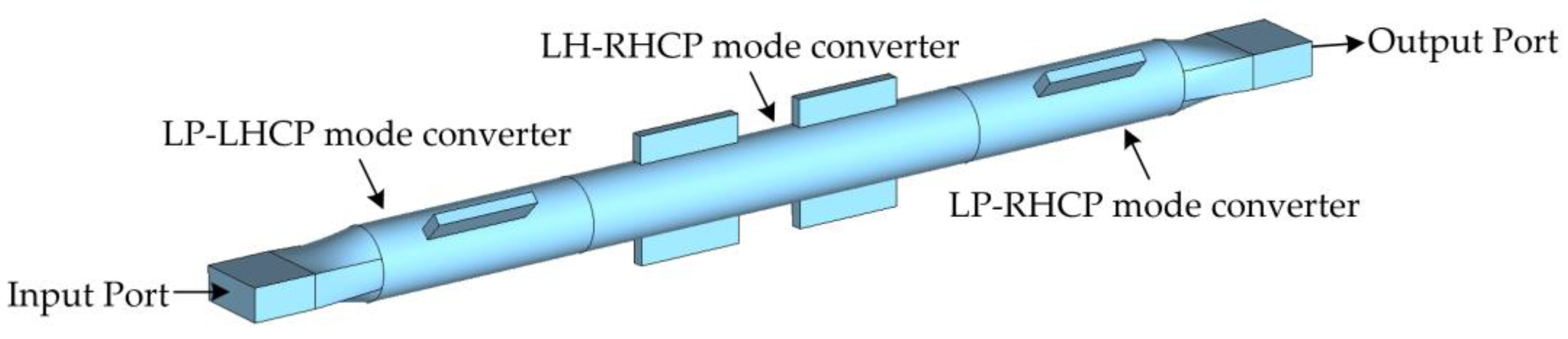
Figure 2.
Schematic diagram of the structure of the circular polarizer.
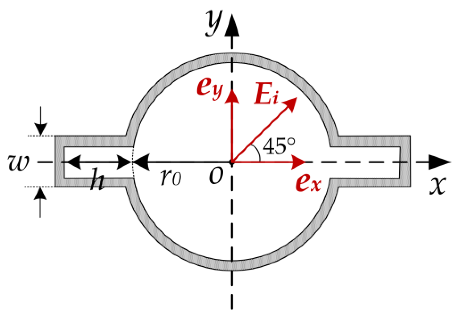
Figure 3.
ex-ey and e1-e2coordinate system.
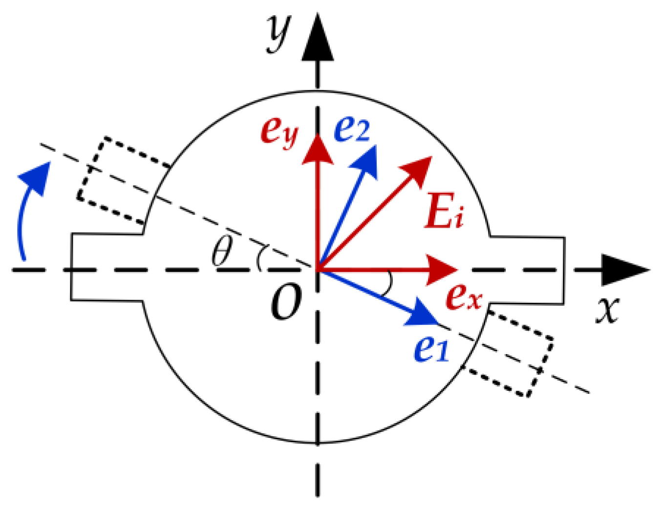
Figure 4.
Schematic diagram of the structure of the LP- LHCP mode converter.
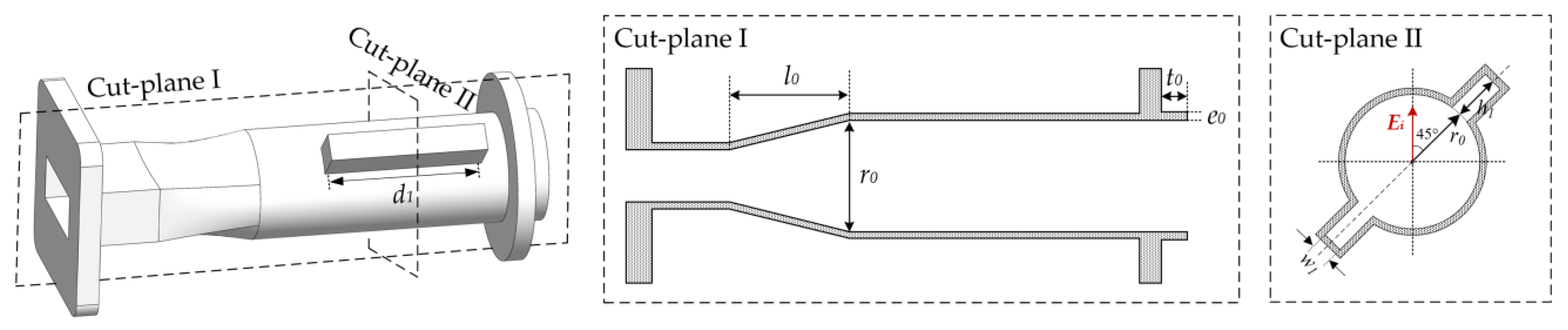
Figure 5.
Magnitude and phase difference of S parameters for the LP-LHCP mode converter.
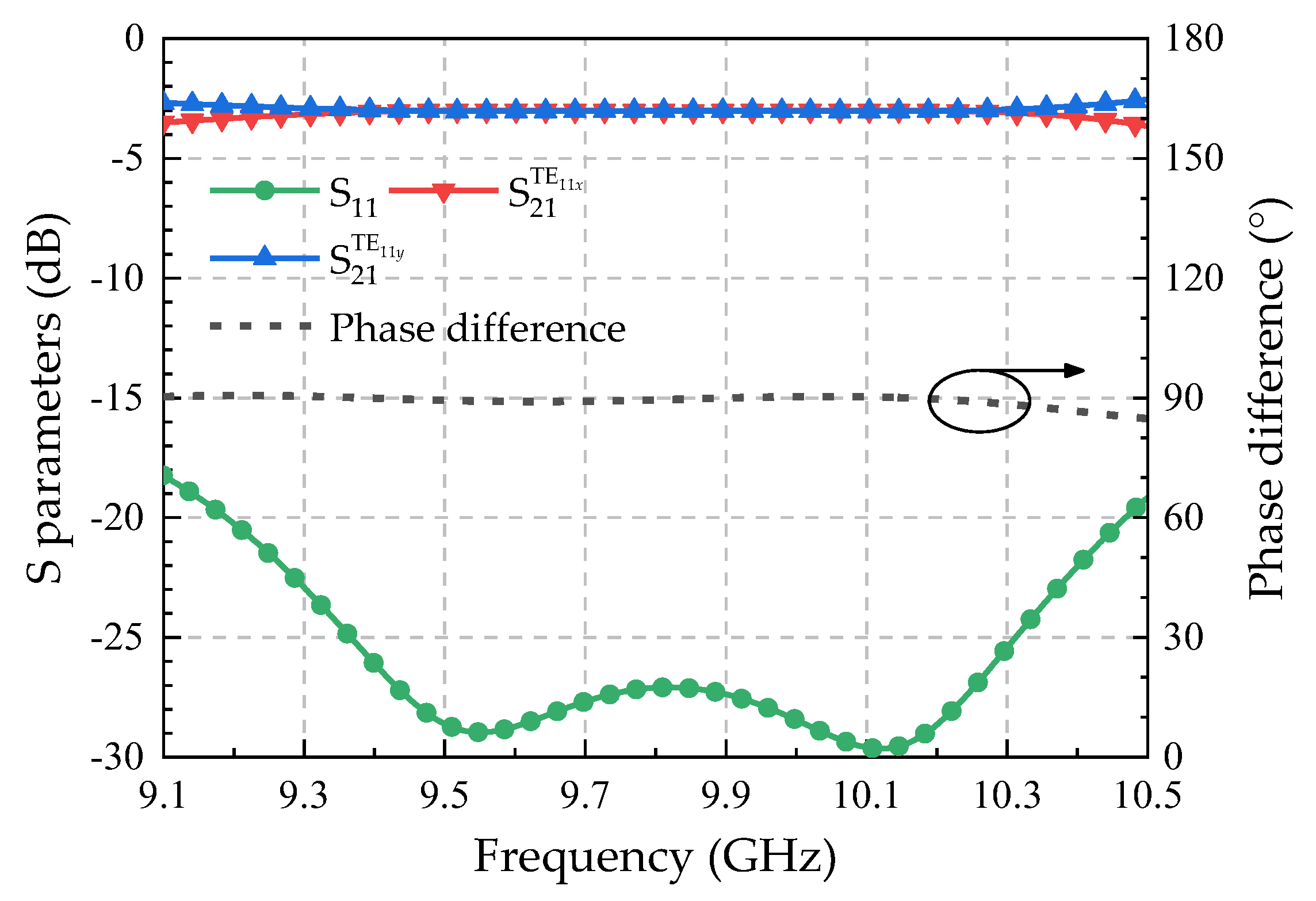
Figure 6.
Conversion efficiency and axial ratio of the LP-LHCP mode converter.
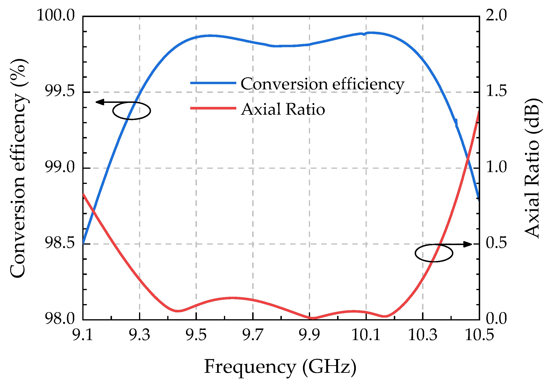
Figure 7.
Schematic diagram of the structure of the LH-RHCP mode converter.
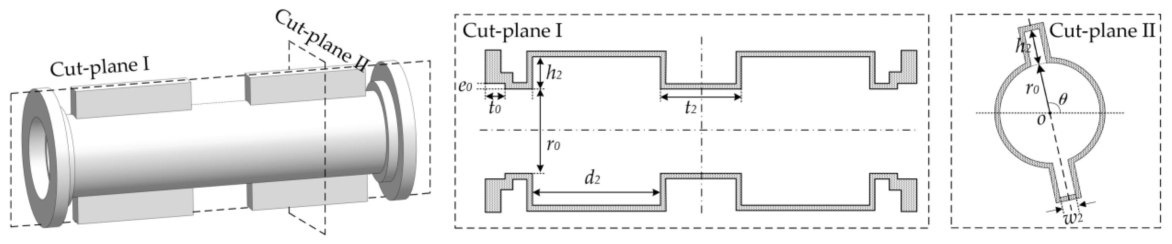
Figure 8.
Schematic diagram of the structure of the LH-RHCP mode converter.
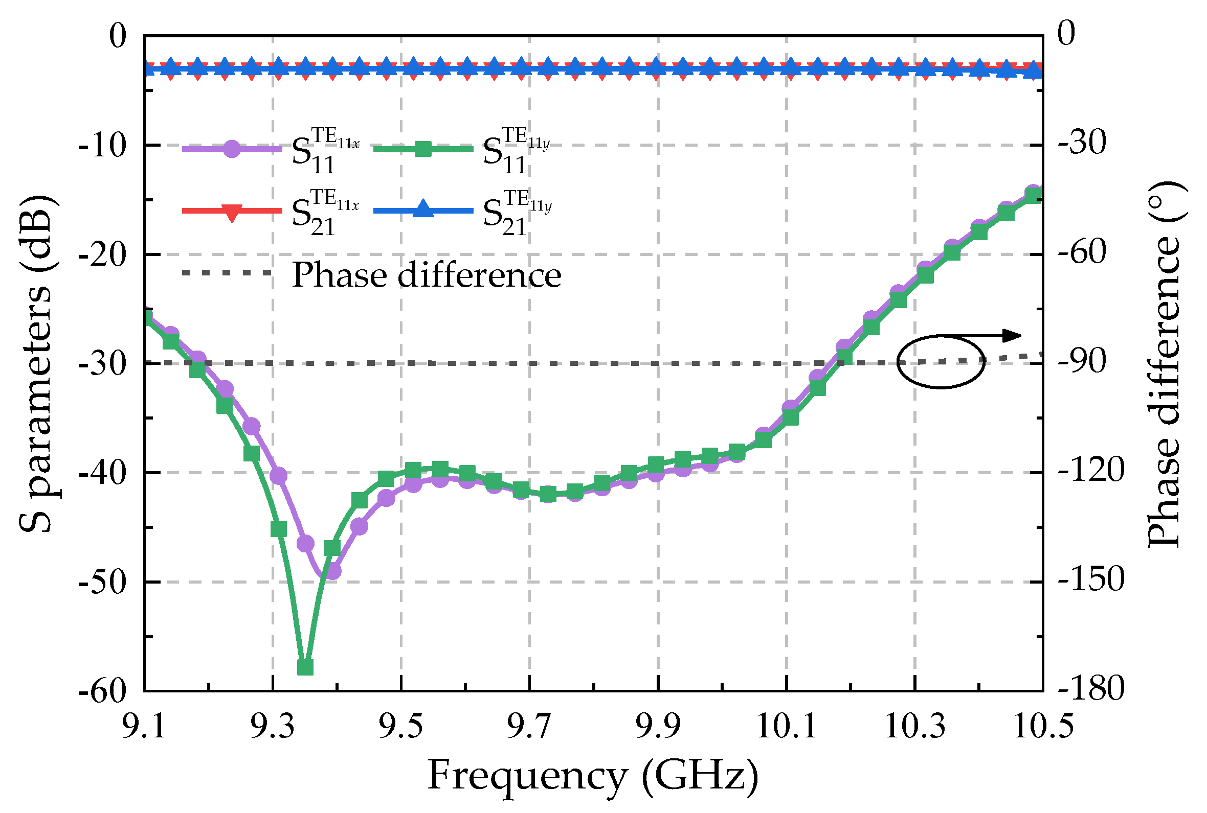
Figure 9.
Conversion efficiency and axial ratio of the LH-RHCP mode converter.
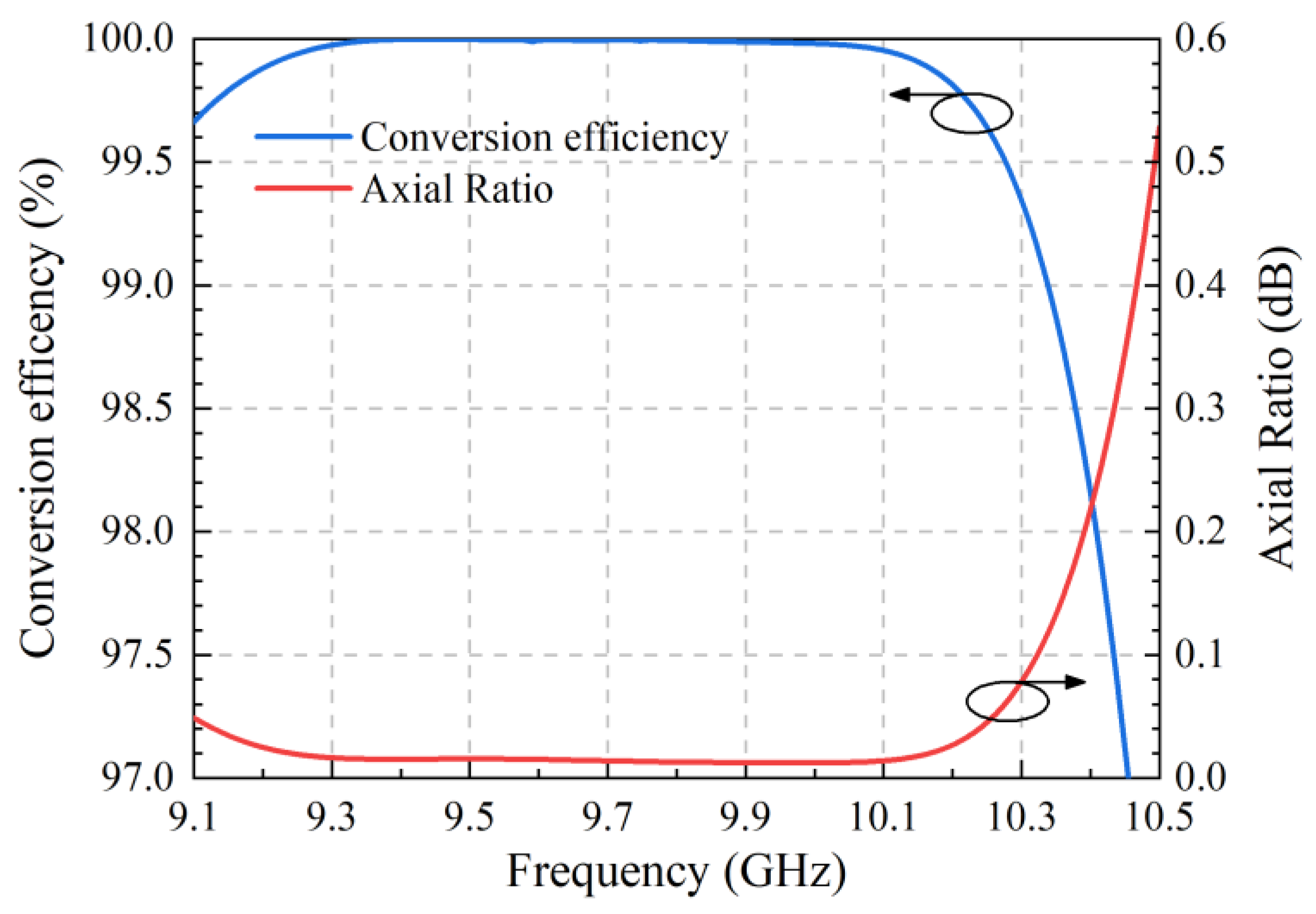
Figure 10.
Schematic diagram of the structure of the LP-RHCP mode converter.
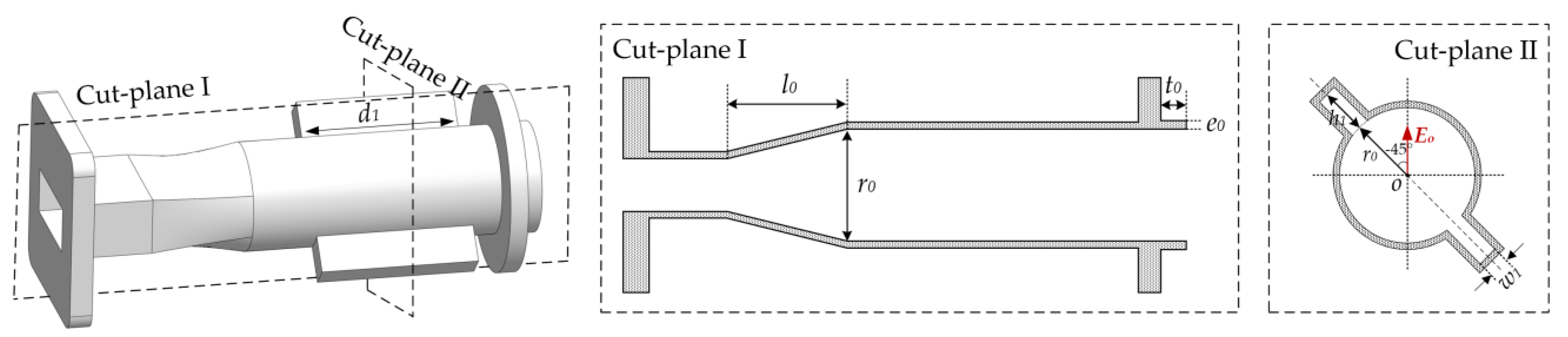
Figure 11.
Conversion efficiency and axial ratio of the LH-RHCP mode converter.
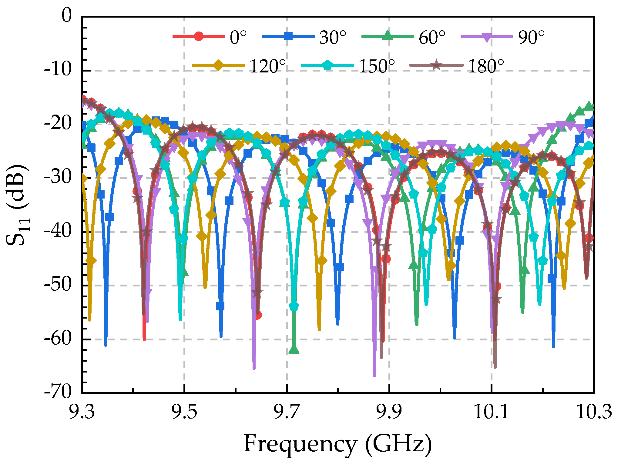
Figure 12.
Conversion efficiency and axial ratio of the LH-RHCP mode converter.

Figure 13.
Output phase of the phase shifter at varying rotation angles.
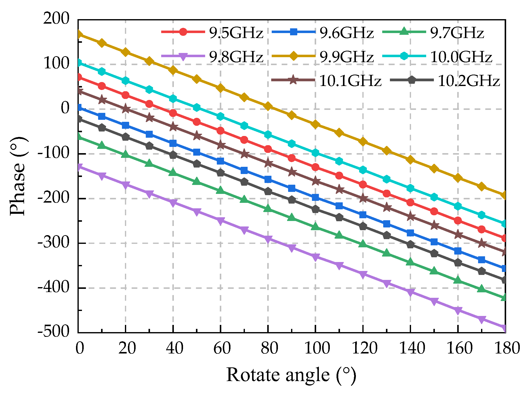
Figure 14.
Output phase of the phase shifter at varying rotation angles.
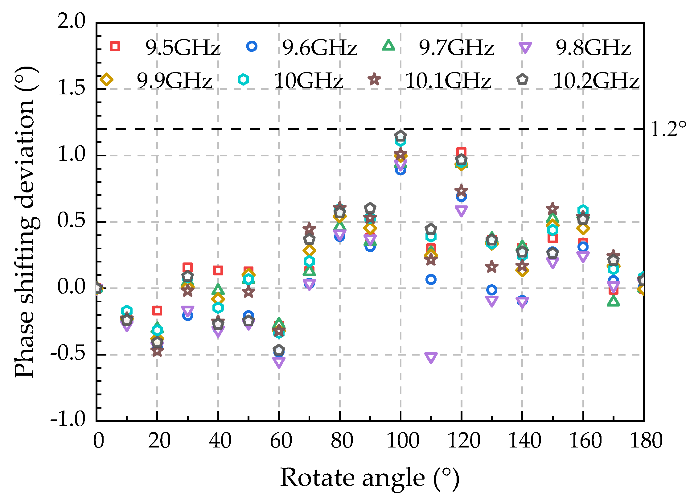
Figure 15.
Electric field distribution of the phase shifter.
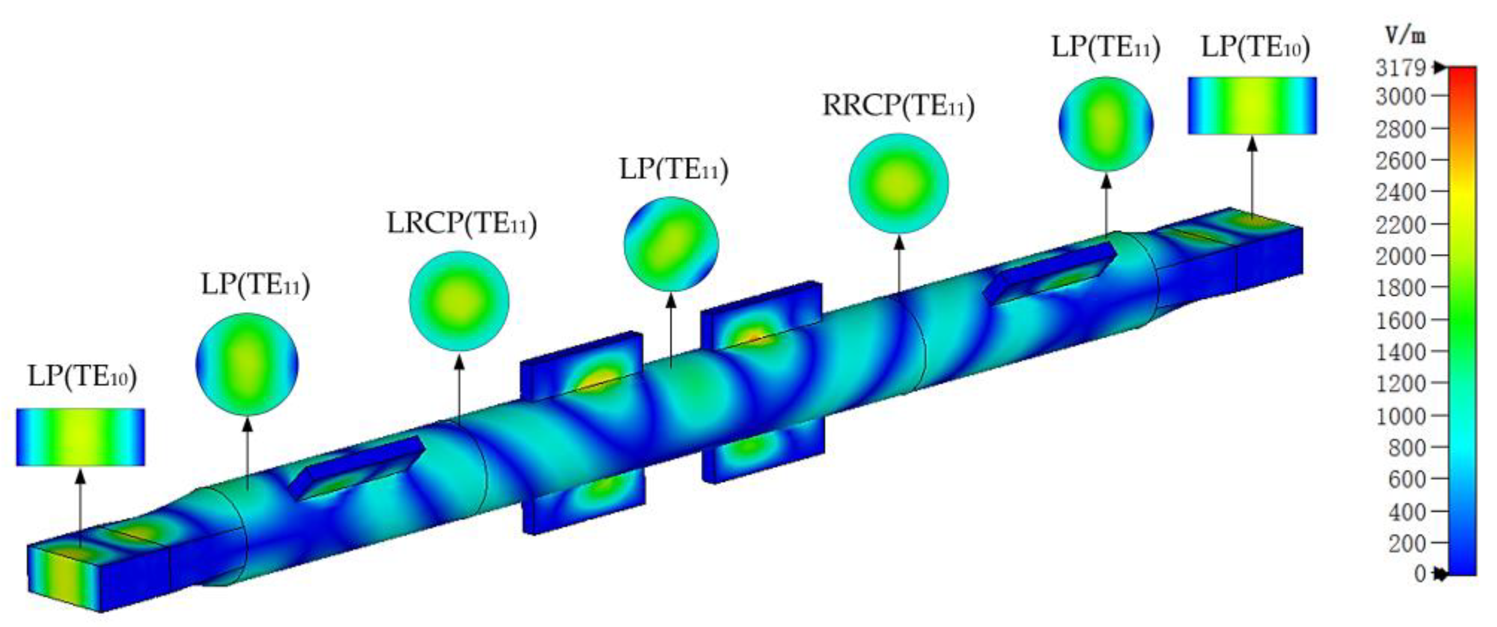
Table 1.
Specific dimensions of the LP-LHCP mode converter (Unit in mm).
| Parameters | Value | Parameters | Value |
| l0 | 23 | h1 | 8.1 |
| r0 | 10.8 | t0 | 5 |
| d1 | 32.7 | e0 | 2 |
| w1 | 3.55 |
Table 2.
Specific dimensions of the LH-RHCP mode converter (Unit in mm).
| Parameters | Value | Parameters | Value |
|---|---|---|---|
| d2 | 32.7 | t2 | 20.6 |
| w2 | 3.7 | t0 | 5 |
| h2 | 8.2 | e0 | 2 |
Disclaimer/Publisher’s Note: The statements, opinions and data contained in all publications are solely those of the individual author(s) and contributor(s) and not of MDPI and/or the editor(s). MDPI and/or the editor(s) disclaim responsibility for any injury to people or property resulting from any ideas, methods, instructions or products referred to in the content. |
© 2023 by the authors. Licensee MDPI, Basel, Switzerland. This article is an open access article distributed under the terms and conditions of the Creative Commons Attribution (CC BY) license (http://creativecommons.org/licenses/by/4.0/).
Copyright: This open access article is published under a Creative Commons CC BY 4.0 license, which permit the free download, distribution, and reuse, provided that the author and preprint are cited in any reuse.


