1. Introduction
Microrobotics is a promising field for wide application areas such as medicine [
1] and environmental monitoring [
2]. These small robots can perform various tasks in confined spaces to achieve minimally invasive surgery [
3] and drug delivery [
4]. Considering the minuteness of the robots, which limits their manipulation abilities, achieving precise control and navigation of a microrobot becomes a formidable task. In order to manipulate the robots, researchers have utilized many techniques such as optical [
5], electrostatic [
6], acoustic [
7], and magnetic actuation [
8]. Magnetic actuation has advantages for microrobot manipulation, as it enables non-invasive control of the microrobot inside the body, offers high precision and control over movement, and is energy-efficient [
9,
10].
Given the specific environment in which microrobots are intended to be utilized, both the biocompatibility and biodegradability of a microrobot are important factors to consider for a range of tasks [
11]. In this paper, we fabricate the microrobots by using a biocompatible and biodegradable alginate material to create a soft deformable body [
12]. When the contact between alginate solution and calcium chloride occurs, the soft microrobots are created through crosslinking process [
13]. In order to impart the magnetic properties, the Iron oxide particles with a diameter of approximately 50-100 nm were incorporated into the alginate. This way allows us to control and manipulate the alginate microrobots under the external magnetic fields [
14].
In order to create a more complex fluidic media for demonstrating a real-world application in a viscoelastic environment, we utilized polyacrylamide (PAA) which has non-Newtonian fluid properties. Non-Newtonian and Newtonian fluids are different in their response to applied forces [
15]. The actuation of the microrobot can be a nonlinear function of viscosity, yield stress, thixotropy, and rheopexy in non-Newtonian fluid [
16]. Consequently, the behavior of non-Newtonian fluids tends to be more intricate and less predictable compared to Newtonian fluids, posing additional complexities in forecasting the motion of a microrobot. The use of a magnetically actuated soft microrobot in a non-Newtonian fluid has important implications for its potential applications in targeted drug delivery and non-invasive surgery [
17]. Non-Newtonian fluids are common in biological systems, including the fluids inside the human body. To replicate a non-Newtonian fluidic environment, we utilized PAA in a water-based solution. By examining the performance of the microrobot in this particular fluid, we can enhance our comprehension of its behavior in diverse and intricate environments, such as the human body. In our previous study [
13], the locomotion of the microsnowman robot was examined in a Newtonian fluidic environment using rotational magnetic fields to facilitate a rolling motion. Our objective in this paper is to comprehend the complex motion modes that arise in viscoelastic fluid environments. By utilizing PAA, we employed snowman-shaped soft microbots to demonstrate the feasibility of both wiggling and tumbling movements. The predominant factors influencing the wiggling motion are the viscoelastic properties of the fluid and the non-uniform magnetization. Furthermore, we established that modifying the viscoelastic properties of the fluid can affect these motion modes. Additionally, we exhibited that swarms of microbots have the capacity to exhibit non-uniform behavior within a complex environment. Understanding this knowledge can be pivotal in advancing the development of microrobotic systems for targeted drug delivery and non-invasive surgery. It empowers us to optimize the design and functionality of these systems, ensuring their effectiveness in operating within such environments. Ultimately, the use of soft microrobots in such applications has the potential to greatly improve the precision, efficiency, and safety of medical treatments, making it an exciting area of research with a significant potential impact on human healthcare.
The outline of the paper is structured as follows. The Materials and Methods section provides a detailed explanation of the rolling and tumbling motions. In the Results section, the rolling and tumbling motions are showcased using a single robot and a swarm of microsnowman robots under a rotating magnetic field. A brief discussion regarding the results has been included in the Conclusions section.
2. Materials and Methods
2.1. Fabrication of Microsnowman and Preparation of Non-Newtonian Fluids
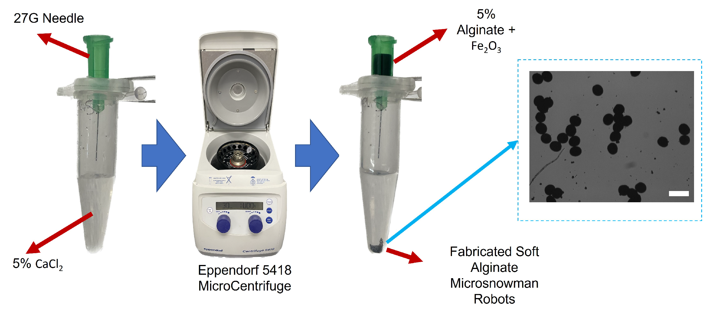
The microsnowman robots are fabricated from alginate hydrogels by an extrusion-based microcentrifugal method in
Figure 1. By cross-linking alginate-sodium and calcium chloride, a hydrogel can be produced. To steer the robots under the external magnetic field, paramagnetic nanoparticles are encapsulated with the solution. The method of fabrication was described in detail in our previous paper [
13].
In experiments investigating the behavior of soft microbots in viscoelastic polymeric solutions, PAA, a water-soluble polymer, was employed. PAA is widely utilized in various industries, including wastewater treatment [
18] and soil conditioning [
19], due to its water solubility and diverse applications. The solutions were prepared by using PAA (Sigma Aldrich, 92560) and added to deionized water in 0.25%, 0.5%, and 1% weight per volume (w/v) ratio [
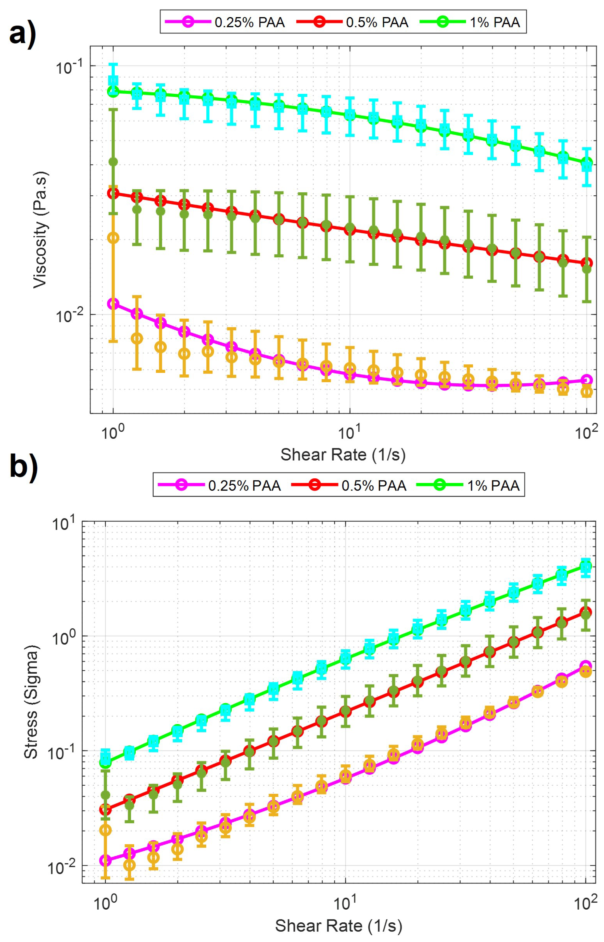
20]. The same rheological measurement was performed after each solution was prepared. The measurement is accomplished using a rheometer [TA Instruments Discovery Hybrid (DHR-3)] attached to a 40mm Peltier plate geometries disc (513400.905, H/A-AL ST SMART-SWAP). In the beginning, a series of calibrations are needed before the experiment, including geometry inertia and rotational mapping calibrations. After the calibration, a sample of one solution is added to the plate. When the measurement starts, a zero gap is applied on the contact surfaces between the equipment geometry and the sample solution, and the shear rate increases from 1 to 100 (1/s) with a 60-second step time. The total time to sweep over the share-rate range was 21 minutes. Measurements were made for 0.25%, 0.5%, and 1% PAA concentrations and were characterized by stress and viscosity concerning shear rates. The results in the logarithmic scale can be seen in
Figure 2. It is clearly seen from the figure that there is a significant viscosity decrease with respect to the increase of shear rate for three concentrations of PAA. These results indicate that PAA has a shear-thinning pseudo-plastic property. Second-order curve fitting is applied to the raw data. The results of curve fitting can be seen in
Table 1. The curve fitting presented in
Figure 2 demonstrated a linear relationship between the sample’s viscosity and shear rate. In this case, the viscosity decreases linearly with increasing shear rate. The improving R-squared values suggested a better fit between the regression model and the data when the PAA concentration increases. For example, at 0.25% concentration PAA, the R-squared value was 0.8685, indicating 86.85% of the viscosity and shear rate data has a linear relationship. At 1% concentration PAA, the R-squared value increased to 0.9966, indicating that nearly all the data expressed linearity between viscosity and shear rate. Such results showed that the precision of such linearity between viscosity and shear rate improved when the PAA concentration increased.
2.2. Experimental System
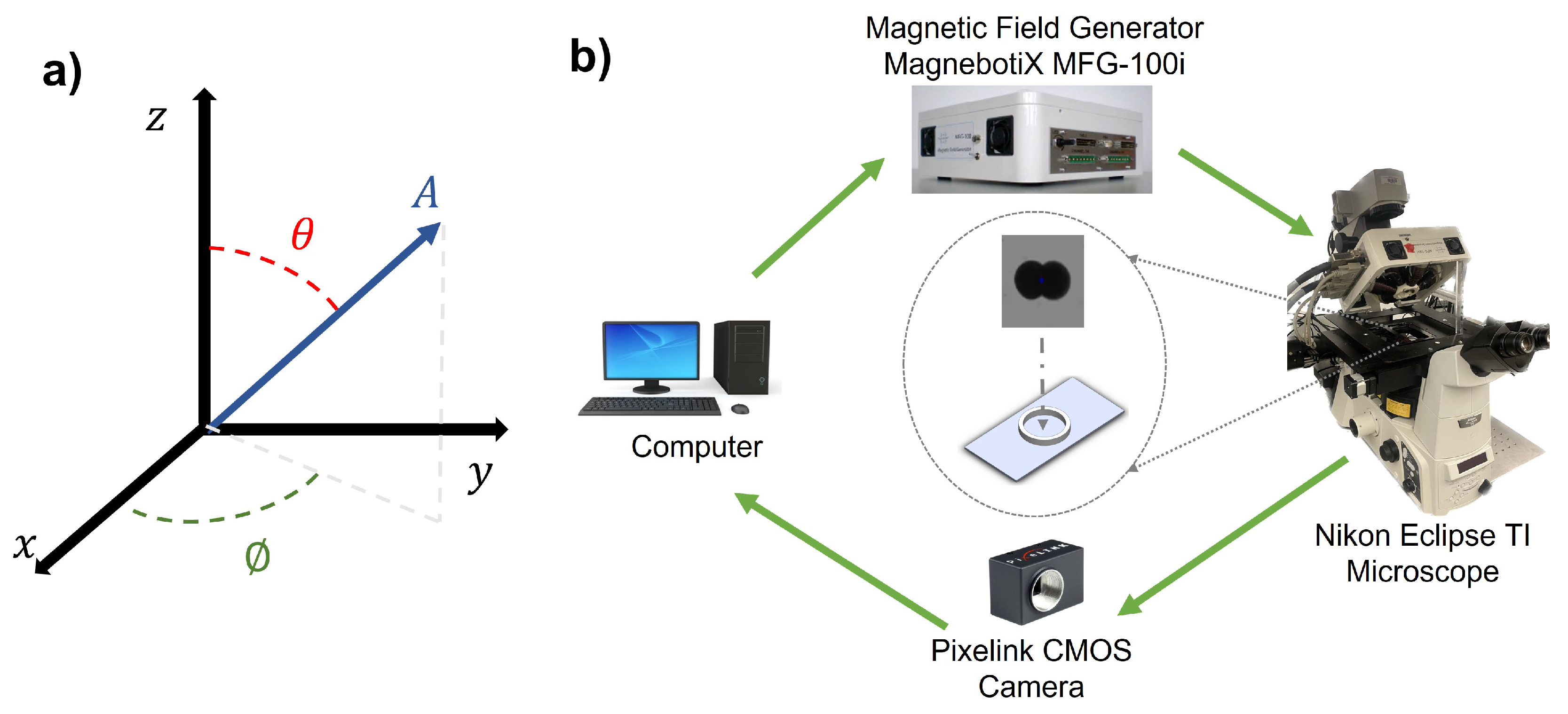
The schematic of the experimental system is depicted in
Figure 3. The integrated electromagnetic coil system (Magnebotix MFG-100i) is installed on the inverted microscope (Nikon Eclipse TI). The power supply (ECB-820) was controlled by robot operation system (ROS) based software. A complementary metal-oxide-semiconductor (CMOS) color camera (Pixelink D734CU-T, with resolution 2048 × 2048 pixels and 30 frames per second) via
Nikon C-mount and an objective lens (Nikon
Acromat) was used to capture video from the microscope on the bright-field mode.
The amplitude and direction of rotating magnetic fields with the electromagnetic coil system were generated by using the following formula,
where
A,
, and
represent the magnetic field magnitude (mT), azimuth, and inclination angles (degree), respectively. The magnetic field was controlled by custom software with user input.
2.3. Locomotion Methods
This paper explores the manipulation of the alginate microsnowman robot using tumbling and wiggling locomotion methods within a PAA solution. Rolling locomotion can be found in our previous paper [
13]. As a result of the non-Newtonian fluid properties of the environment, such as uncertainty and non-linearity, the dominant factor affecting the propulsion of the microrobot’s location is the time-varying drag force. The thermal and fluidic effects such as Brownian motion are neglected due to the Reynolds number [
21]. The highest calculated Reynolds number during our experiments is
.
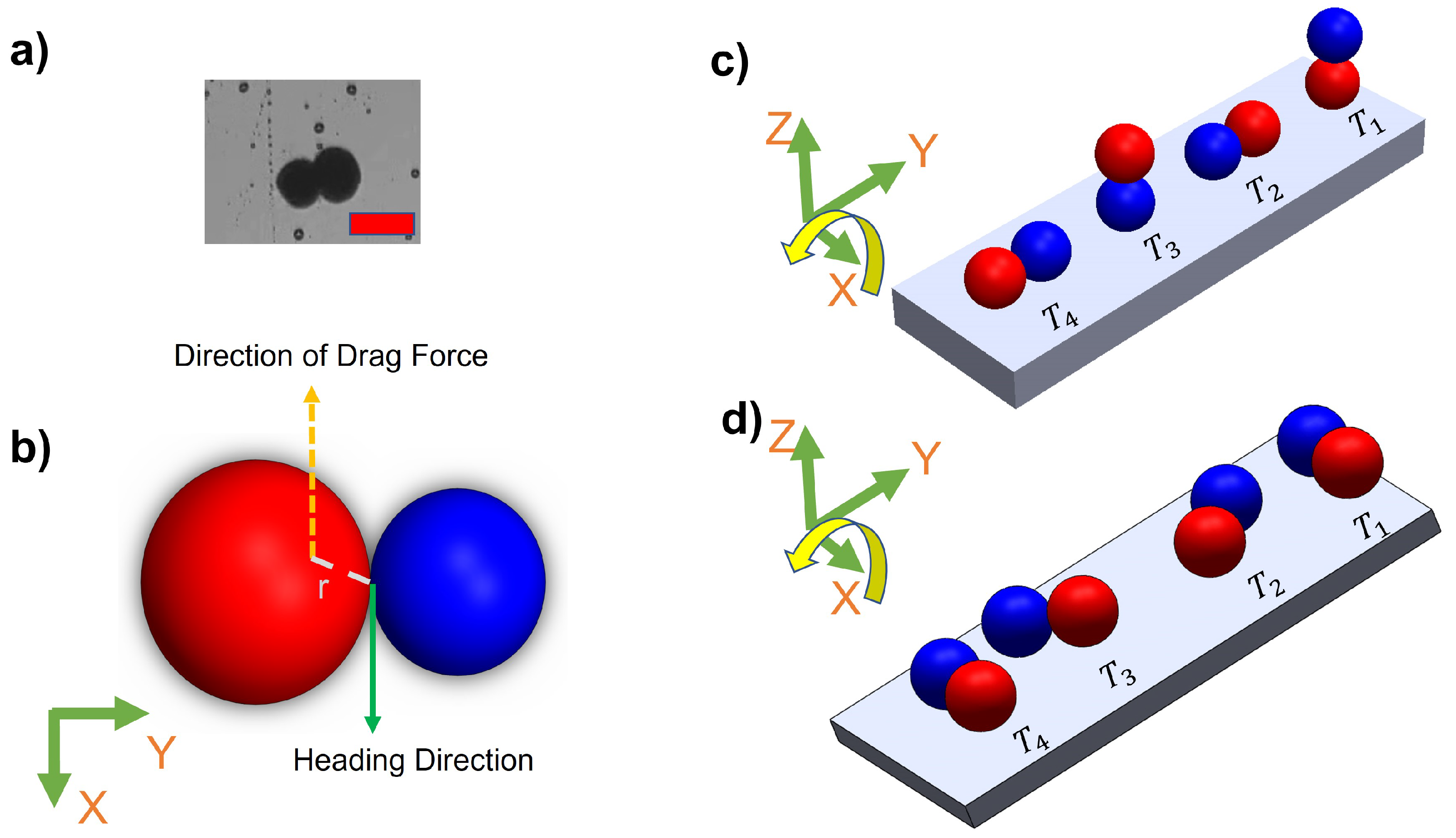
Figure 4a and b illustrate the heterogeneous structure of microsnowman robots, consisting of two spheres of different sizes. However, it is important to note that due to the dimensional differences between the spheres, the applied torque and forces may undergo slight distortions. The overall applied torque (
) on the microrobot can be calculated by,
where
M is the applied magnetic torque, r is the difference between the geometrical and dipole centers, and
F is the drag force in 3D space. Because of the fabrication of microsnowman structures using the extrusion-based centrifugal method, the diameter sizes of each droplet for microsnowman configuration differ, which causes instability in the motion of the robot.
2.3.1. Tumbling
Tumbling motion is mostly preferred for navigation in complex environments [
22]. The higher radius of gyration and the ability to jump over the obstacles of tumbling motion enables the microrobots to effectively navigate and adjust to uneven terrains. To create the tumbling motion, the microsnowman robot rotates around its short axis [
23]. The motion direction and rotation axis are aligned [
24].
Figure 4c explains this phenomenon. The microrobot adapts its orientation and moves in various directions within complex environments by adopting a microsnowman configuration for tumbling. This enables it to overcome the conformational structures of the water-soluble PAA chain present in the fluid.
2.3.2. Wiggling
There is a high shear force due to the non-Newtonian fluid behavior of PAA. Non-Newtonian fluids, like PAA solutions, exhibit viscosity that varies with the applied shear rate or stress (
Figure 2). This means that the shear force experienced by objects moving through the PAA solution can be significant, depending on the flow conditions and the concentration of the PAA solution. As a result, we observed that the microsnowman robots moved in a constrained fashion even though the rotating magnetic field is applied with the same conditions. Additionally, the uncertainty associated with non-Newtonian fluids gives rise to this situation. Based on our experimental observations, we conclude that this motion resembles a wiggling motion.
Figure 4d shows the steps of wiggling motion with a soft microsnowman microrobot on a substrate surface.
3. Results
In this section, a series of experiments were performed using soft microsnowman robots to showcase their controllability within complex environments. Firstly, we conducted an analysis of the velocity profile in relation to the magnitude of the rotating magnetic field. Subsequently, we present the experimental results for microsnowman robots within a swarm, focusing on their tumbling and wiggling motions.
The experiments were executed in a sample chamber in the center of the microscope, as seen in the center of
Figure 3. The microsnowman robots were carefully selected and placed into the polydimethylsiloxane (PDMS) sample chamber (approximately, 5 mm diameter with 1.5 mm height). To prevent water evaporation and maintain fluid stability, a cover slip glass (25 mm × 18 mm, No 1.) was utilized as support. The PDMS chamber was prepared by mixing silicon elastomer (SYLGARD 184) and silicon elastomer curing agent (SYLGARD 1184) with a 7:1 weight ratio. Then, the mixture was heated on the hot plate to 60
C for 2 hours.
3.1. Velocity Analysis with Microsnowman Robots in Non-Newtonian Fluids
The velocity profile of the microsnowman robot was investigated to explore the motion characteristics in non-newtonian fluidic environments. The velocity results were derived using image processing techniques, calculating the instantaneous velocity frame-by-frame. These values were then averaged over each magnetic field set point.
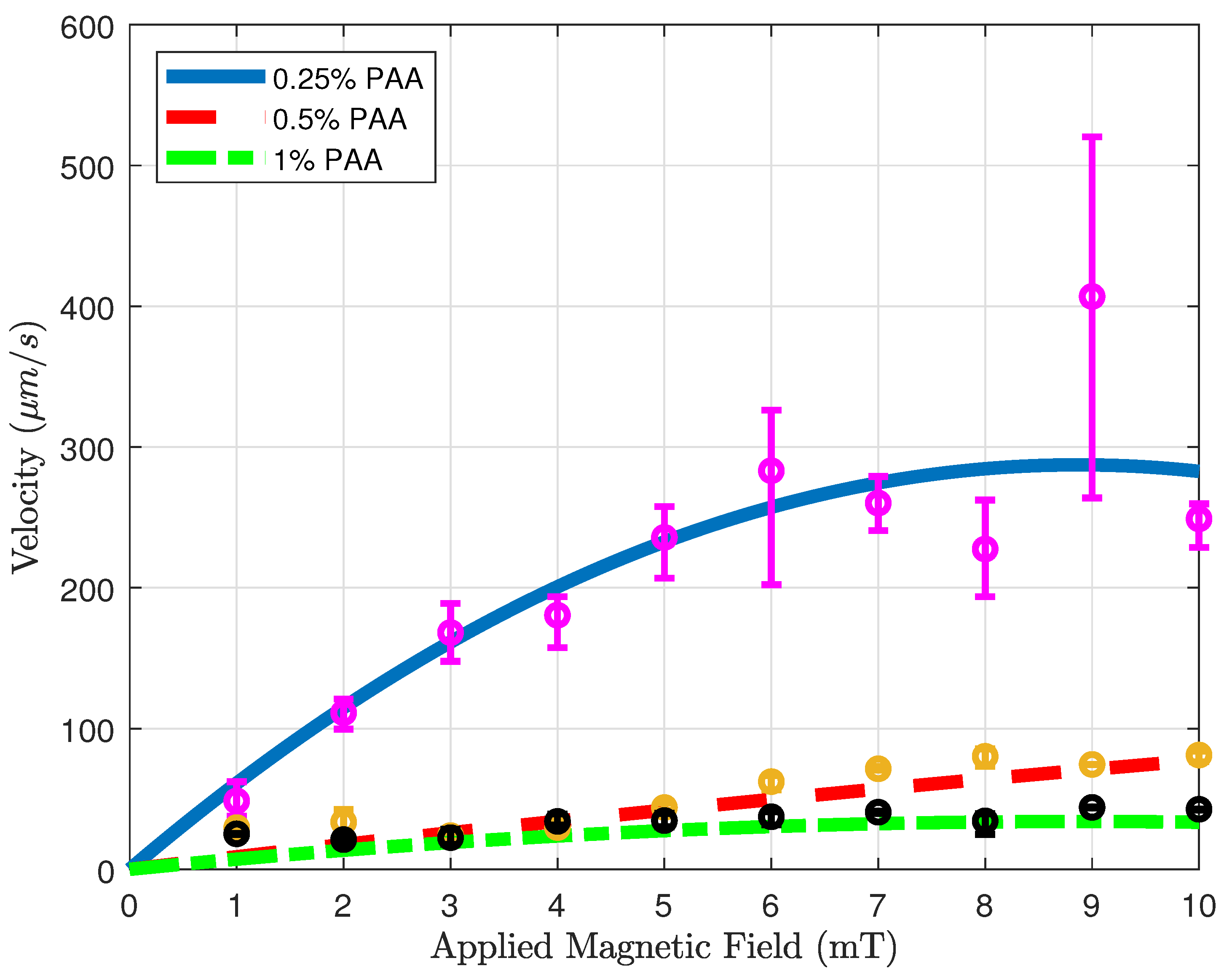
Figure 5 shows the velocity versus applied magnetic field results of microsnowman robots in PAA solutions. The concentration of the solution in the experiments was
%,
%, and 1%, respectively. To ensure result consistency, the robot sizes were maintained within the range of 275-280 microns, while also maintaining a uniform density of iron oxide particles. For each concentration, we tried to use the same location for the experiments to eliminate the effect of fluid-structure interactions in the non-Newtonian fluid. For each magnetic field result, we repeated the same rotating magnetic field for the same motion three times. To interpolate the results more clearly, a curve fitting is applied to the averaged velocities for the results of three experiments. The statistical analysis of the second-order fitting can be seen in
Table 2. The average velocities increase with the use of a lower concentration of PAA. As a result of the shear-thinning characteristics of PAA, the velocity responses exhibited a gradual decrease in relation to the applied magnetic field for three different PAA concentrations. This effect is particularly evident in the case of 0.25% PAA. In higher shear rates, the loss of contact between the substrate surface and the microsnowman occurred as a result of molecular interactions in non-Newtonian fluids, leading to a slip phenomenon between the robot and the substrate. This situation caused higher errors after 5 mT was applied magnetic field. At the 10 mT applied magnetic field intensity, we observed slippage occurring as a result of the deformation of the soft microsnowman body, leading to a decrease in velocity. In the case of 0.5% and 1% PAA concentrations, the predominant motion mode observed was wiggling. However, for the 0.25% PAA concentration, additional motion modes of tumbling and rolling were observed within the magnetic fields of 8-10 mT and 3-4 mT, respectively.
3.2. Swarm Control
Swarm control of microrobots involves the coordinated control of a substantial number of small robots, enabling them to perform tasks collectively [
25]. Drug delivery using a swarm of microrobots requires greater control over the delivery process, which has the potential to enhance the effectiveness of the medication [
26]. Through the synchronization of microrobot movements, it becomes feasible to administer drugs with heightened precision and accuracy. This coordinated approach ensures that the drugs reach their intended targets effectively while reducing the potential for side effects. Additionally, swarm control enables the delivery of multiple drugs simultaneously, which can improve treatment outcomes [
27]. By using multiple microrobots to deliver different drugs to different targets, it is possible to create customized drug delivery regimens that are tailored to the patient’s individual needs. For these reasons, we attempted swarm control to understand the coordinated behavior of the microsnowmen in non-Newtonian fluids.
Figure 6 demonstrates the swarm control of microsnowman robots in non-Newtonian fluidic environments. Each robot was exposed to a uniform rotating magnetic field. At the lowest concentration, the robots showed the same wiggling motion modes. However, at the
% PAA concentration, we observed a tumbling motion in the yellow path, whereas the other paths were manipulated with wiggling motion. PAA can exhibit heterogeneous characteristics. Due to its structure and composition, PAA can display non-uniform or varying properties across different regions or within a given system. Factors such as polymerization conditions, polymer chain branching, and the presence of impurities can contribute to the heterogeneous nature of PAA. Hence, the location has the ability to influence the environmental conditions, as demonstrated in
Video 1b. During the microsnowman robot’s left turn along the yellow path, the dominant influence of additional drag force prevented the robot from achieving a tumbling motion. Additionally, the results revealed a decrease in the controllability of the microsnowman robots as the concentration of PAA increased.
Table 3 presents a comparison of the traveled distances between wiggling motion and tumbling motion in a 0.5% PAA solution, as observed in
Video 1b. The table clearly shows that tumbling motion covers a greater distance when subjected to a uniformly rotating magnetic field signal. The disparity in performance can be attributed to variations in magnetization directions and geometries among the robots. In this context, single particles outperform microsnowman-shaped robots. This discrepancy arises due to the applied drag force, which negatively affects the motion of robots, especially those with larger surface areas like microsnowman robots, in contrast to single particles.
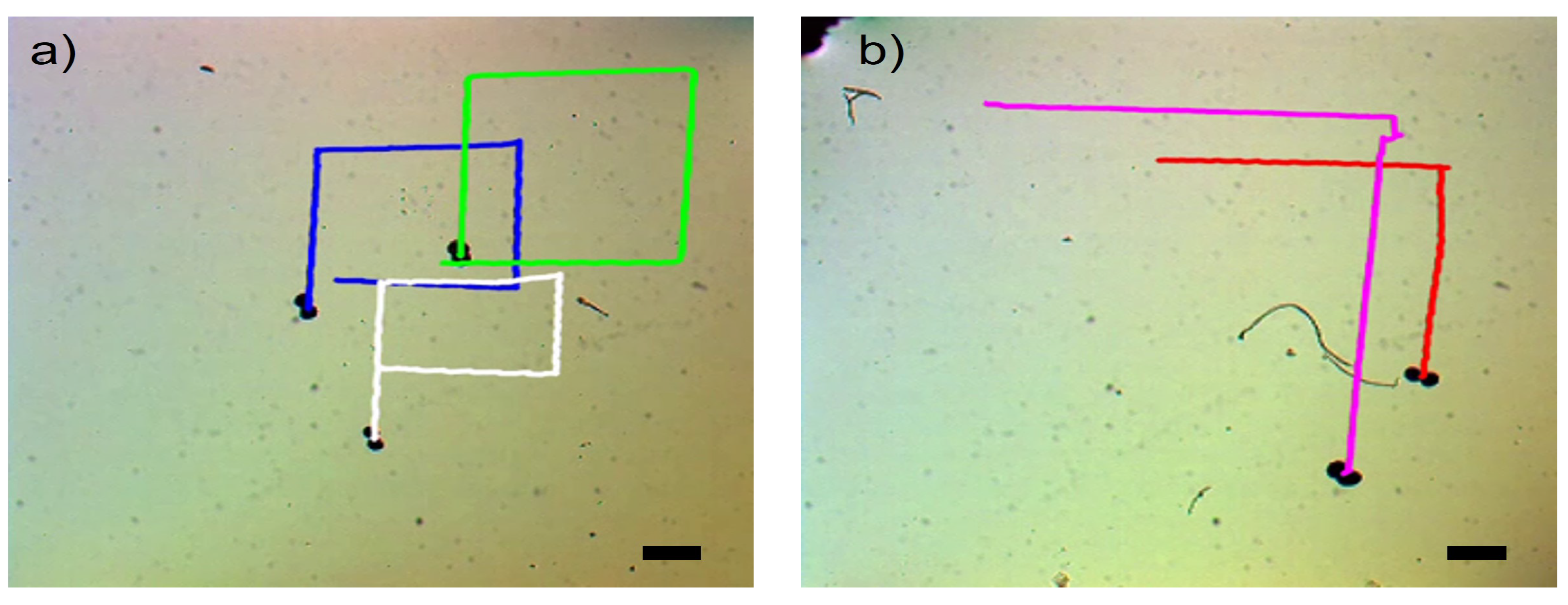
Figure 7 showcases the swarm control outcomes of the microsnowman robot, specifically focusing on the tumbling and wiggling motions. In
Figure 7a, the effects of the PAA fluid’s uncertainty are evident. While the green path follows a square shape, the blue and white paths exhibit a rectangular pattern. This video presentation highlights the non-Newtonian behavior of PAA.
Figure 7b demonstrates two distinct manipulation modes operating under the influence of the same global magnetic field.
The tumbling and wiggling motions are represented by the pink and red paths, respectively. This distinction arises from the varying dipole directions of the robots. The robot following the pink path is magnetized along its long axis, while the robot in the red path is magnetized along its short axis.
Figure 7 clearly illustrates that tumbling motion outperforms wiggling motion in terms of the traveled distance when subjected to a single magnetic input. The velocity calculation for tumbling motion yielded a value of
, while the velocity for wiggling motion was determined to be
.
4. Conclusion
In this study, the surface locomotion methods of microsnowman-shaped alginate microrobots were investigated within viscoelastic fluidic environments, with a focus on their applicability to real-world drug delivery scenarios. In comparison to swimming as a means of drug delivery, surface motions like rolling, tumbling, and wiggling offer advantages due to their improved controllability in various scenarios.We utilized polyacrylic acid (PAA) as a viscoelastic fluidic medium at concentrations of 0.25%, 0.5%, and 1%. Rheology analysis was performed specifically for the 0.5% and 1% PAA concentrations. The microsnowman robots were fabricated using an extrusion-based centrifugal method. Our objective was to investigate the complex motion modes that arise in viscoelastic fluid environments. By employing PAA, we deployed the microsnowman microrobots to demonstrate the achievability of both wiggling and tumbling motions. We found that wiggling resulted from the combination of viscoelastic fluid environments and non-uniform magnetization. Additionally, we showed that altering the viscoelastic properties can influence these motion behaviors, highlighting the non-uniform behavior of microbot swarms in complex environments. To characterize the motion in this complex environment, we conducted a velocity analysis against the magnitude of the applied rotational magnetic field. The robots were wirelessly controlled in an open-loop mode to track rectangular paths for each concentration of PAA solution. Tumbling and wiggling motions were achieved and compared both individually and in swarm configurations to see their feasibility for drug delivery in bodily fluidic environments. As a future direction, we plan to employ a nonlinear closed-loop controller in the experimental system.
Supplementary Materials
The following supporting information can be downloaded at the website of this paper posted on
Preprints.org. Video V1a, V1b, and V1c: Motion in non-Newtonian Fluids; Video V2a: Swarm Control Results for Tumbling Motion; Video V2b: Comparison of Tumbling vs. Wiggling Motions.
Author Contributions
Conceptualization, G.K. and M.J.K.; methodology, G.K. and M.J.K.; formal analysis, G.K., Y.C.D. and Z.W. investigation, G.K. and M.J.K.; resources, M.J.K.; data curation, G.K., Z.W. and Y.C.D.; writing—original draft preparation, G.K.; writing—review and editing, G.K., L.W.R., S.J.P. and M.J.K.; project funding acquisition, M.J.K. All authors have read and agreed to the published version of the manuscript.
Funding
This research was funded by NSF IIS #2130775. S. J. P. was supported by Basic Research Program through the National Research Foundation of Korea (NRF) funded by the Ministry of Education (No. 2018R1A6A1A03025526 and No. 2020R1I1A3063782).
Acknowledgments
Authors would like to thank Grace Josephson for the invaluable discussion and proofreading.
Conflicts of Interest
The authors declare no conflict of interest. The funders had no role in the design of the study; in the collection, analyses, or interpretation of data; in the writing of the manuscript; or in the decision to publish the results.
Abbreviations
| PAA |
Polyacrylamide |
| w/v |
weight per volume |
References
- Nelson, B.J.; Kaliakatsos, I.K.; Abbott, J.J. Microrobots for minimally invasive medicine. Annual Review of Biomedical Engineering 2010, 12, 55–85. [Google Scholar] [CrossRef]
- Shoji, K.; Morishima, K.; Akiyama, Y.; Nakamura, N.; Ohno, H. ; Autonomous environmental monitoring by self-powered biohybrid robot. In Proceedings of the IEEE International Conference on Mechatronics and Automation (ICMA 2016), Harbin, China, 7 August 2016; pp. 629–634. [Google Scholar]
- Sitti, M.; Ceylan, H.; Hu, W.; Giltinan, J.; Turan, M.; Yim, S.; Diller, E. Biomedical applications of untethered mobile milli/microrobots. Proceedings of the IEEE 2015, 103, 205–224. [Google Scholar] [CrossRef]
- Ongaro, F.; Niehoff, D.; Mohanty, S.; Misra, S.A. Contactless and Biocompatible Approach for 3D Active Microrobotic Targeted Drug Delivery. Micromachines 2019, 10, 504. [Google Scholar] [CrossRef]
- Grexa, I.; Fekete, T.; Molnár, J.; Molnár, K.; Vizsnyiczai, G.; Ormos, P.; Kelemen, L. Single-cell elasticity measurement with an optically actuated microrobot. Micromachines 2020, 11, 882. [Google Scholar] [CrossRef]
- Basset, P.; Kaiser, A.; Bigotte, P.; Collard, D.; Buchaillot, L. A large stepwise motion electrostatic actuator for a wireless microrobot. In Proceedings of the Fifteenth IEEE International Conference on Micro Electro Mechanical Systems (MEMS 2002), Las Vegas, NV, USA, 24 January 2002; pp. 606–609. [Google Scholar]
- Kaynak, M.; Dirix, P.; Sakar, M.S. Addressable acoustic actuation of 3D printed soft robotic microsystems. Advanced Science 2020, 7, 2001120. [Google Scholar] [CrossRef]
- Xu, T.; Yu, J.; Yan, X.; Choi, H.; Zhang, L. Magnetic Actuation Based Motion Control for Microrobots: An Overview. Micromachines 2015, 6, 1346–1364. [Google Scholar] [CrossRef]
- Shao, Y.; Fahmy, A.; Li, M.; Li, C.; Zhao, W.; Sienz, J. Study on magnetic control systems of micro-robots. Frontiers in Neuroscience 2021, 15, 736730. [Google Scholar] [CrossRef]
- Koleoso, M.; Feng, X.; Xue, Y.; Li, Q.; Munshi, T.; Chen, X. Micro/nanoscale magnetic robots for biomedical applications. Materials Today Bio 2020, 8, 100085. [Google Scholar] [CrossRef]
- Kim, J.; Park, H.; Yoon, C. Advances in Biodegradable Soft Robots. Polymers 2022, 14, 4574. [Google Scholar] [CrossRef]
- Sun, J.; Tan, H. Alginate-Based Biomaterials for Regenerative Medicine Applications. Materials 2013, 26, 1285–1309. [Google Scholar] [CrossRef]
- Kararsiz, G.; Duygu, Y.C.; Rogowski, L.W.; Bhattacharjee, A.; Kim, M.J. Rolling Motion of a Soft Microsnowman under Rotating Magnetic Field. Micromachines 2022, 13, 1005. [Google Scholar] [CrossRef]
- Ali, J.; Cheang, U.K.; Liu, Y.; Kim, H.; Rogowski, L.; Sheckman, S.; Kim, M.J. Fabrication and magnetic control of alginate-based rolling microrobots. AIP Advances 2016, 6, 125205. [Google Scholar] [CrossRef]
- Aghakhani, A.; Pena-Francesch, A.; Bozuyuk, U.; Cetin, H.; Wrede, P.; Sitti, M. High shear rate propulsion of acoustic microrobots in complex biological fluids. Science Advances 2022, 8, eabm5126. [Google Scholar] [CrossRef]
- Campo-Deaño, L. Assessing the Dynamic Performance of Microbots in Complex Fluid Flows. Applied Sciences 2016, 6, 410. [Google Scholar] [CrossRef]
- Belharet, K.; Folio, D.; Ferreira, A. Control of a magnetic microrobot navigating in microfluidic arterial bifurcations through pulsatile and viscous flow. In Proceedings of the 2012 IEEE/RSJ International Conference on Intelligent Robots and Systems, Vilamoura-Algarve, Portugal, 7 October 2012; pp. 2559–2564. [Google Scholar]
- Kurenkov, V.F.; Hartan, H.G.; Lobanov, F.I. Application of polyacrylamide flocculants for water treatment. Butlerov Communications 2002, 3, 31–40. [Google Scholar]
- Fijałkowska, G.; Szewczuk-Karpisz, K.; Wiśniewska, M. Polyacrylamide soil conditioners: the impact on nanostructured clay minerals’ aggregation and heavy metals’ circulation in the soil environment. In Proceedings of the 7th International Conference Nanotechnology and Nanomaterials (NANO2019), Lviv, Ukraine, 30 August 2019; pp. 111–127. [Google Scholar]
- Rogowski, L.W.; Ali, J.; Zhang, X.; Wilking, J.N.; Fu, H. C.; Kim, M.J. Symmetry breaking propulsion of magnetic microspheres in nonlinearly viscoelastic fluids. Nature Communications 2021, 12, 1116. [Google Scholar] [CrossRef]
- Cheang, U.K.; Kim, H.; Milutinović, D.; Choi, J.; Kim, M.J. Feedback control of an achiral robotic microswimmer. Journal of Bionic Engineering 2017, 14(2), 245–259. [Google Scholar] [CrossRef]
- Xie, J.; Bi, C.; Cappelleri, D.J.; Chakraborty, N. Dynamic Simulation-Guided Design of Tumbling Magnetic Microrobots. ASME J. Mechanisms Robotics 2021, 13, 041005. [Google Scholar] [CrossRef]
- Niedert, E.E.; Bi, C.; Adam, G.; Lambert, E.; Solorio, L.; Goergen, C.J.; Cappelleri, D.J. A Tumbling Magnetic Microrobot System for Biomedical Applications. Micromachines 2020, 11, 861. [Google Scholar] [CrossRef]
- Yan, G.; Xu, B.; Shi, X.; Zong, Y.; Wu, Y.; Liu, J.; Mei, Y. Anisotropic magnetized tubular microrobots for bioinspired adaptive locomotion. Applied Materials Today 2022, 27, 101457. [Google Scholar] [CrossRef]
- Wu, R.; Zhu, Y.; Cai, X.; Wu, S.; Xu, L.; Yu, T. Recent Process in Microrobots: From Propulsion to Swarming for Biomedical Applications. Micromachines 2022, 13, 1473. [Google Scholar] [CrossRef] [PubMed]
- Banharnsakun, A.; Achalakul, T.; Batra, R.C. Drug delivery based on swarm microrobots. International Journal of Computational Intelligence and Applications 2016, 15, 1650006. [Google Scholar] [CrossRef]
- Akter, M.; Keya, J.J.; Kayano, K.; Kabir, A.M.R.; Inoue, D.; Hess, H.; Kakugo, A. Cooperative cargo transportation by a swarm of molecular machines. Science Robotics 2022, 7, eabm0677. [Google Scholar] [CrossRef] [PubMed]
Figure 1.
The fabrication scheme of soft alginate microsnowman robot. Calcium chloride (CaCl, 5% w/v) was placed into a centrifuge tube (5 mL) with a sodium alginate (Na-Alginate, 5% w/v) in iron oxide solution (FeO, 5% concentration, 50-100 nm particle size in diameter). The mixture is centrifuged with the microcentrifuge (Eppendorf 5418). Using the effect of centrifugal and gravitational forces, the droplets are generated and crosslinked into microsnowman robots. The generated particles are shown on the right side of the figure. The scale bar is set to 300 .
Figure 2.
Rheology analysis results for PAA solutions. Purple, red, and green lines with cyan, green, and yellow error bars display the 0.25%, 0.5%, and 1% PAA concentrations. The data points from the characterization experiments are shown for three solutions, respectively. a) Viscosity vs. Shear Rate. b) Stress vs. Shear Rate.
Figure 3.
a) Schematic of the magnetic control system in 3D coordinates. b) Experimental setup. The data flow is illustrated by the green arrows. The prepared sample chamber and the microsnowman robot are positioned at the center.
Figure 3.
a) Schematic of the magnetic control system in 3D coordinates. b) Experimental setup. The data flow is illustrated by the green arrows. The prepared sample chamber and the microsnowman robot are positioned at the center.
Figure 4.
Demonstration of motion modes on the substrate surface. a) An image of a heterogeneous microsnowman robot. The red scale bar is 250 . b) The effects of imposed or applied forces in the 2-D plane. The left particle is intentionally drawn slightly larger than the right particle to demonstrate the heterogeneity of the fabricated soft particles. The relative distance between the geometrical and magnetic dipole centers is shown by a dashed white line and represented with the letter r. c) The steps of tumbling motion on a substrate surface. Red and blue colors represent the presumable north and south poles, respectively. The direction of the applied torque caused by the rotating magnetic field is shown by the yellow arrow. Each position of the robot was labeled from to with respect to time. The north and south poles are represented with blue and red colors, respectively. d) The illustration of wiggling motion on the surface.
Figure 5.
Velocity vs. magnetic field magnitude results for various concentrations. Blue solid, red dashed, and green dotted-dashed lines with the magenta, yellow, and black error bars represent 0.25, 0.5, and 1 % PAA solutions.
Figure 5.
Velocity vs. magnetic field magnitude results for various concentrations. Blue solid, red dashed, and green dotted-dashed lines with the magenta, yellow, and black error bars represent 0.25, 0.5, and 1 % PAA solutions.
Figure 6.
Swarm control of microsnowman robots under uniform global input. The scale bars represent 400
. The video can be found in the supplementary material (See
Video 1a, 1b, and 1c). The complete durations of each video are 31, 64, and 459 seconds for 0.25%, 0.5%, and 1% PAA concentrations.
Figure 6.
Swarm control of microsnowman robots under uniform global input. The scale bars represent 400
. The video can be found in the supplementary material (See
Video 1a, 1b, and 1c). The complete durations of each video are 31, 64, and 459 seconds for 0.25%, 0.5%, and 1% PAA concentrations.
Figure 7.
Complex locomotion in the non-Newtonian fluidic environment under single global rotating magnetic input. The scale bar is set to 500 microns.
a) Swarm control results for tumbling motion (See
Video 2a).
b) Comparison of tumbling vs. wiggling motions. The pink and red paths are tracked for tumbling and wiggling motions (See
Video 2b).
Table 1.
The curve fitting results for PAA characterizations.
Table 1.
The curve fitting results for PAA characterizations.
| PAA Concentrations |
|
|
|
| R-Squared Values () |
|
|
|
Table 2.
The curve fitting results for Velocity vs. Applied Magnetic Field.
Table 2.
The curve fitting results for Velocity vs. Applied Magnetic Field.
| PAA Concentrations |
|
|
|
| R-Squared Values () |
|
|
|
Table 3.
Comparison for Distance and Velocity Global Uniform Magnetic Field
Table 3.
Comparison for Distance and Velocity Global Uniform Magnetic Field
| |
Tumbling (Yellow) |
Rolling (Green) |
Rolling (Red) |
Rolling (Blue) |
Single Particle |
| Distance () |
573.10 |
223.85 |
187.16 |
148.46 |
267.87 |
| Velocity () |
37.21 |
14.53 |
12.15 |
9.64 |
17.39 |
|
Disclaimer/Publisher’s Note: The statements, opinions and data contained in all publications are solely those of the individual author(s) and contributor(s) and not of MDPI and/or the editor(s). MDPI and/or the editor(s) disclaim responsibility for any injury to people or property resulting from any ideas, methods, instructions or products referred to in the content. |
© 2023 by the authors. Licensee MDPI, Basel, Switzerland. This article is an open access article distributed under the terms and conditions of the Creative Commons Attribution (CC BY) license (http://creativecommons.org/licenses/by/4.0/).
