0. Introduction
Maneuverability is one of the important performance characteristics of aircraft and a notable feature of high-performance fighter jets. The fuel tank is a vital component of the aircraft platform and the only part for fuel storage and transfer. During the maneuvering process, the fuel inside the tank undergoes intense motion under the influence of external forces, which can impact the tank's structure and flight stability. The movement of fuel can create a shock load on the fuel tank, so it is necessary to predict the areas affected by the shock load to prevent fatigue damage. The dynamic changes in the free liquid surface during fuel movement alter the mass distribution and liquid level height distribution within the tank, leading to a shift in the fuel's center of gravity, which can have adverse effects on the aircraft's flight attitude or stability. As the flight range increases, the mass of fuel carried by the aircraft also increases, and the fuel movement caused by maneuvering can bring greater impact on the tank wall. Therefore, studying the motion characteristics of fuel inside the tank under maneuvering excitation has important engineering application value for flight stability and fuel tank safety.
For the problem of free surface motion of liquids in limited space, it has attracted the attention of engineers from various countries [1-3]. Currently, numerical simulation methods for free surface problems mainly include Arbitrary Lagrange Euler (ALE) method, Volume of Fluid (VOF) method, and Smoothed Particle Hydrodynamics (SPH) method. Among them, the Smoothed Particle Hydrodynamics (SPH) method is a grid-free calculation method proposed by Lucy [
4] and Gingold [
5] in 1977, which has been widely used in the field of fluid dynamics [6-7]. Compared with traditional grid-based methods, the SPH method is suitable for simulating problems involving large deformations, free surfaces, moving boundaries, and deformable boundaries. It solves the problem of grid distortion caused by large deformations in traditional grid-based numerical methods when solving the problem of liquid shaking. However, the SPH method also has shortcomings or areas for improvement, such as poor calculation accuracy when particles are irregularly distributed, low algorithm stability, and incomplete boundary handling [
8]. Literature [
9] proposes using a finite number of particles to discretize the fluid domain, with each particle carrying physical information such as velocity and pressure, called the Finite Pointset Method (FPM). This method is an important development of the SPH method in the field of grid-free calculation.
The movement of fuel in a fuel tank under excitation is a complex and highly nonlinear free surface phenomenon with randomness. Wang Li et al. [
10] simulated the interaction between fuel and the fuel tank during unmanned aerial vehicle launch using the Arbitrary Lagrange Euler (ALE) method. Yang Shanglin et al. [
11] used the finite element software ABAQUS and a traditional Volume of Fluid (VOF) method to obtain the shape changes of fuel during a semi-roll process. Yang Rui [
12] simulated the fuel sloshing of a wing fuel tank under steady axis rotation using the ALE method, while Liu Fu et al. [
13] used the Smoothed Particle Hydrodynamic (SPH) method to calculate the fuel movement characteristics of an auxiliary fuel tank during pitch motion.
The above-mentioned studies explored the free surface problem of fuel under simple working conditions using methods such as ALE, SPH, and VOF, but did not consider the movement of fuel under complex overloads. This paper uses the Finite Pointset Method (FPM) to numerically simulate the movement characteristics of fuel in a typical flat fuel tank during maneuvering. The aim is to capture the characteristics of the free surface, pressure, and velocity of the fuel, and to provide support for the safety design of aircraft fuel tank systems through in-depth analysis.
For fuel tanks with a high liquid filling ratio (such as spacecraft propellant tanks, aircraft fuel tanks, and tanker trucks), the significant movement of the liquid in a short period of time during motion can cause changes in the system's center of gravity. This, in turn, may have adverse effects on the motion trajectory or attitude of liquid-carrying systems such as spacecraft, aircraft, and tanker trucks. The research findings presented in this paper can provide certain guidance and reference for the structural design of aircraft fuel tanks, overall design of aircraft, optimization of spacecraft propellant tanks, and the design of liquid-carrying ships and other related liquid-carrying systems.
1. Research Object and Numerical Method
1.1. Research Object
The object of this study is the wing fuel tank located in the wing of the aircraft, referred to as the wing tank, as shown in
Figure 1. The tank has a flat shape and a wall thickness of 3mm. The tank is equipped with baffles and related pipelines with flow holes inside, and the baffles mainly include multiple transverse frames and a longitudinal wall, dividing the tank area into multiple small compartments. The tank wall and pipelines are made of aluminum with a density of 2700kg/m3. The tank is not completely filled with liquid fuel, with a fill ratio of 85%. The density of the fuel is 780kg/m3.
To facilitate accurate capturing of the free liquid surface height and impact pressure at different locations, 8 virtual sensors are installed in the tank to measure the oil immersion height, i.e. the corresponding liquid surface height at each position, and sense the impact pressure of the fuel. The position coordinate information of each sensor in the tank is shown in
Table 1, where the X coordinate is based on the origin of the aircraft nose, the Y coordinate is based on the aircraft horizontal reference plane, and the Z coordinate is based on the aircraft symmetry plane, with units all in meters.
1.2. Numerical Calculation Method and Validation
The motion of fuel can be described using the Navier-Stokes (N-S) equations and the incompressibility condition. The Smoothed Particle Hydrodynamics (SPH) method treats the fuel fluid as a large number of discrete, freely moving particles. Based on kernel function interpolation, a correspondence between discrete particles and continuous physical fields can be established, achieving the discretization of the fluid fuel flow physical field.
The field function approximation and point set approximation are two key aspects of the finite point set method. The integral expression
for the field function is as follows:
In the equation,
is a three-dimensional coordinate vector,
is the volume fraction containing
,
is a smooth function, and
is the smoothing length. The density of the point set within the computational domain affects the distribution layout of the points and the size of the smoothing length. The density of any point can be obtained by integrating the density of the neighboring particles around that point.
In the equation,
represents the density of point
,
represents the weight of point
, and
represents the smooth function of point
, which is approximated at point
by taking a weighted average of the function values of all points supported by it within its domain.
The spatial distribution of the point set within the computational domain changes dynamically with time, and the number and positions of the points supported by point are re-iterated at each time step. During the calculation, within the supporting domain of point , other points exert an effect on it through a smoothing function, which is used for the integration interpolation of the central point .
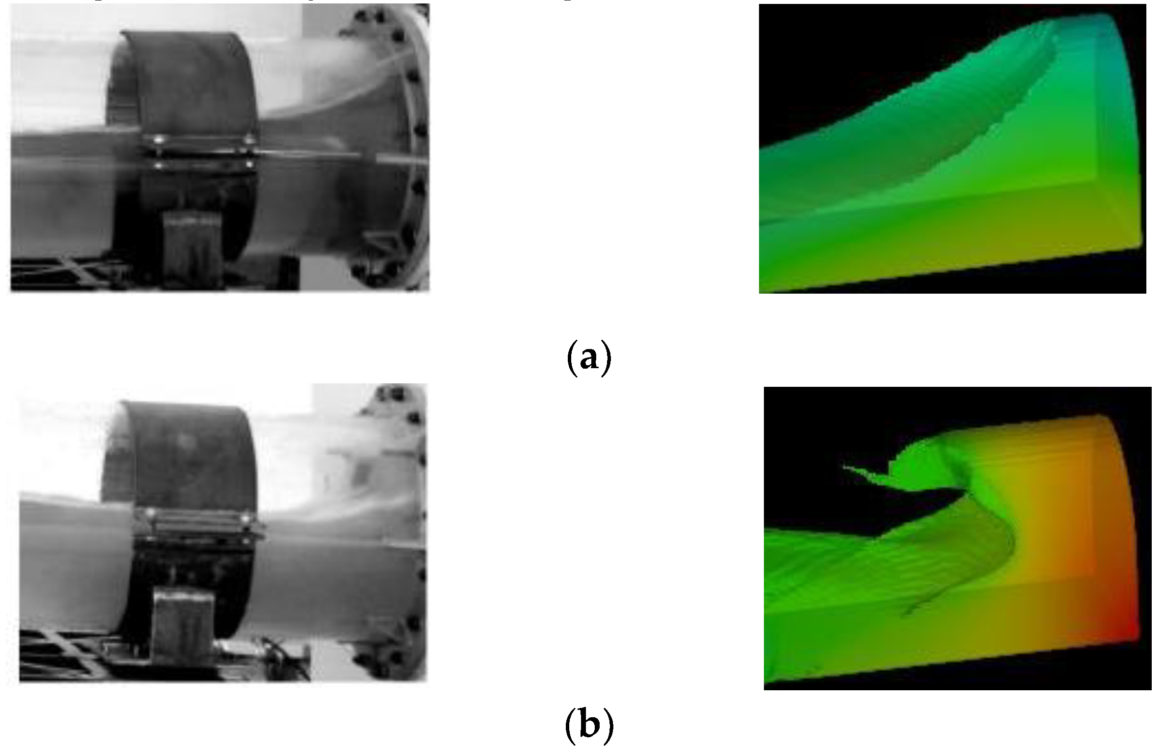
To verify the credibility of the finite point set method in simulating the movement of fuel, a simulation of the movement of a simple elongated cylindrical fuel tank under excitation was conducted and compared with the experimental results in reference [
14], as shown in
Figure 2. It can be seen that the shape of the free liquid surface agrees well with the experimental results. Under excitation, the free liquid surface moves to the right and is constrained by the right boundary, resulting in a smooth surface with a high left side and low right side. As the excitation continues, the liquid on the right is squeezed to a certain degree and flips along the upper boundary to the left, causing collision during the flipping process, and the edge of the free liquid surface is locally broken, forming splashing. Therefore, based on the reference experimental results, the finite point set method has high credibility in simulating the movement of fuel in a fuel tank.
1.3. Boundary Conditions
When the fuel moves in the fuel tank, it includes both the fluid domain occupied by the fuel and the solid domain of the fuel tank structure. Therefore, there is a boundary between the liquid phase and the solid phase. At the boundary between the two-phase media, the fuel cannot leave the fuel tank wall and cannot penetrate the fuel tank wall. Under the condition of neglecting the influence of fuel surface tension and air pressure in the fuel tank on the free liquid surface, the boundary conditions of the free liquid surface are as follows:
Among them, is the normal velocity of the free liquid surface, is the tangential velocity of the free liquid surface, are the pressures on the liquid side and air side of the free liquid surface, respectively. In terms of boundary treatment, for the internal boundary of the fuel tank, it is defined as a no-slip wall surface. The particle positions on this boundary remain fixed, so the velocity of particles on the boundary is zero. The free surface is represented by free boundary particles, and at the beginning of each time step, it is necessary to traverse and detect the free surface particles.
1.4. External Excitation
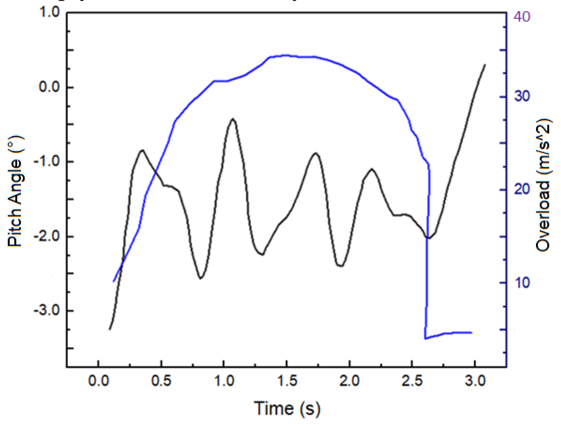
During actual aircraft maneuvering, it is subjected to various excitation factors such as lateral, heading, and normal accelerations, as well as pitch, roll, and other factors. Here, we focus on the influence of heading acceleration and pitch angle variation on fuel movement, that is, the fuel in the tank is simultaneously affected by heading acceleration and pitch excitation.
Figure 3 shows the heading acceleration and pitch angle variation during the aircraft maneuvering process. The overload process includes the loading and unloading phases, both of which are completed in a short time. The 0-1.5s period is the loading phase, during which the acceleration rapidly increases to nearly 35 m/s2 and the flight speed increases rapidly. After 1.5s, it enters the unloading phase, during which the acceleration decreases at a relatively low rate to 32 m/s2, then rapidly decreases to 23 m/s2, and then sharply decreases to nearly 5 m/s2.
2. Results and Analysis
2.1. Fuel Center of Gravity Variation
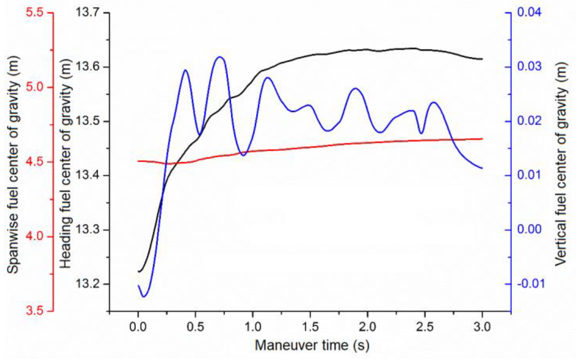
Figure 4 shows the variation of the fuel center of gravity in the heading, pitch, and roll directions during the maneuver process. It can be observed that at the beginning of the maneuver, the acceleration increases sharply, causing the fuel inside the tank to accumulate in the opposite direction of flight, leading to a rapid aft movement of the heading fuel center of gravity. Although the acceleration and pitch angle are still changing after 1.5 seconds, due to the limited volume of the fuel tank, most of the fuel has filled the rear section of the tank, and the variation of the heading fuel center of gravity is not significant after 1.5 seconds. As the acceleration increases rapidly and the fuel flow is blocked by the baffle in the tank, the fuel gathers and flows through the flow holes on the baffle towards the wingtip direction, causing a gradual increase in the roll fuel center of gravity. Overall, the variation amplitude of the roll fuel center of gravity is relatively small. In the middle stage of the maneuver, the fuel rapidly gathers towards the tail of the aircraft, leading to a rapid increase in the vertical fuel center of gravity. Due to the relatively narrow size of the flat fuel tank and the inertia of fuel motion, a part of the accumulated fuel will move towards the front of the aircraft along the top of the tank. Under the influence of gravity, this part of the fuel will gradually fall to the bottom of the fuel tank. During the maneuver process, the fuel inside the tank repeats the process of movement and detachment, resulting in fluctuations in the vertical fuel center of gravity.
2.2. Free Liquid Level Analysis
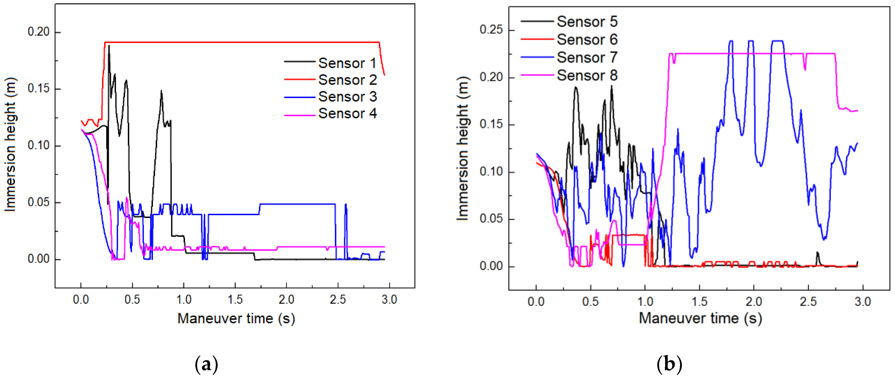
During the maneuvering process, the fluctuations of the fuel free liquid levels monitored by eight sensors are shown in
Figure 5. At t=0, the immersion heights of each sensor are basically consistent, all around 0.12m. Within the first 0.8 seconds of the maneuver, the immersion height of Sensor 1 fluctuates in a "double-peak" pattern, and eventually approaches zero, indicating that there is no fuel present at this location in the later stage of the maneuver. Sensor 2 is located in the middle area of the tank. Within the first 0.3 seconds of the maneuver, the immersion height of Sensor 2 rapidly increases to its maximum position, and then remains at a stable high level, indicating that the fuel at this location occupies the entire region between the bottom and top of the tank. The trend of the immersion height of Sensor 5 is similar to that of Sensor 1. The immersion heights of Sensors 3, 4, and 6 are mostly below 0.05m, indicating that there is little or no fuel at these three measurement locations during the maneuver. From the immersion height curve of Sensor 7, it can be seen that the free liquid level at this location has rapidly and complexly changing characteristics. Within the first 1.5 seconds of the maneuver, the free liquid level oscillates through approximately six peaks/valleys with an average height of 0.07m. In the latter 1.5 seconds of the maneuver, the liquid level gradually decreases after experiencing three high-level oscillations of peaks/valleys, with the liquid level reaching a maximum of 0.23m and a minimum of 0.02m during the oscillation process. The immersion height of Sensor 8 remains below 0.05m in the early stage of the maneuver, and rapidly increases to and stabilizes at 0.22m at t=1.1s, indicating that this location has been rapidly filled with fuel.
2.3. Analysis of Fuel Impact Force
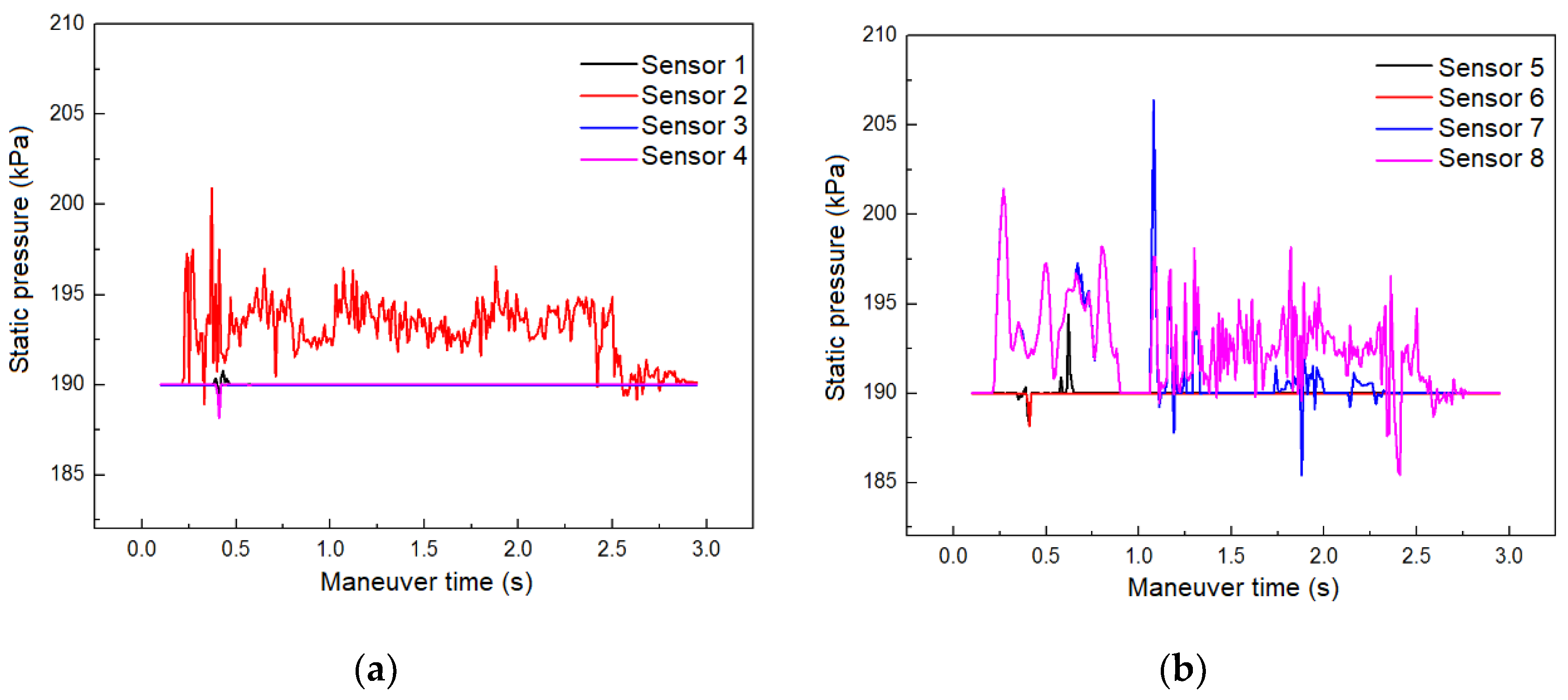
Figure 6 shows the changes in fuel impact pressure monitored by the sensors during the aircraft maneuvering process. It can be seen that the pressure values at the positions of sensors 1, 3, 4, 5, and 6 are relatively stable, indicating that although there is fluctuation in the liquid level at these positions, the change in impact force is not significant. The pressure oscillation situation monitored by sensors 2, 7, and 8 is more complex. The three pressure curves monitored by sensors 2, 7, and 8 all have multiple peaks, which further indicates the existence of complex free surface phenomena at positions 2, 7, and 8. Although the times when these peaks occur are different, the overall trend is that they gradually decrease with damping.
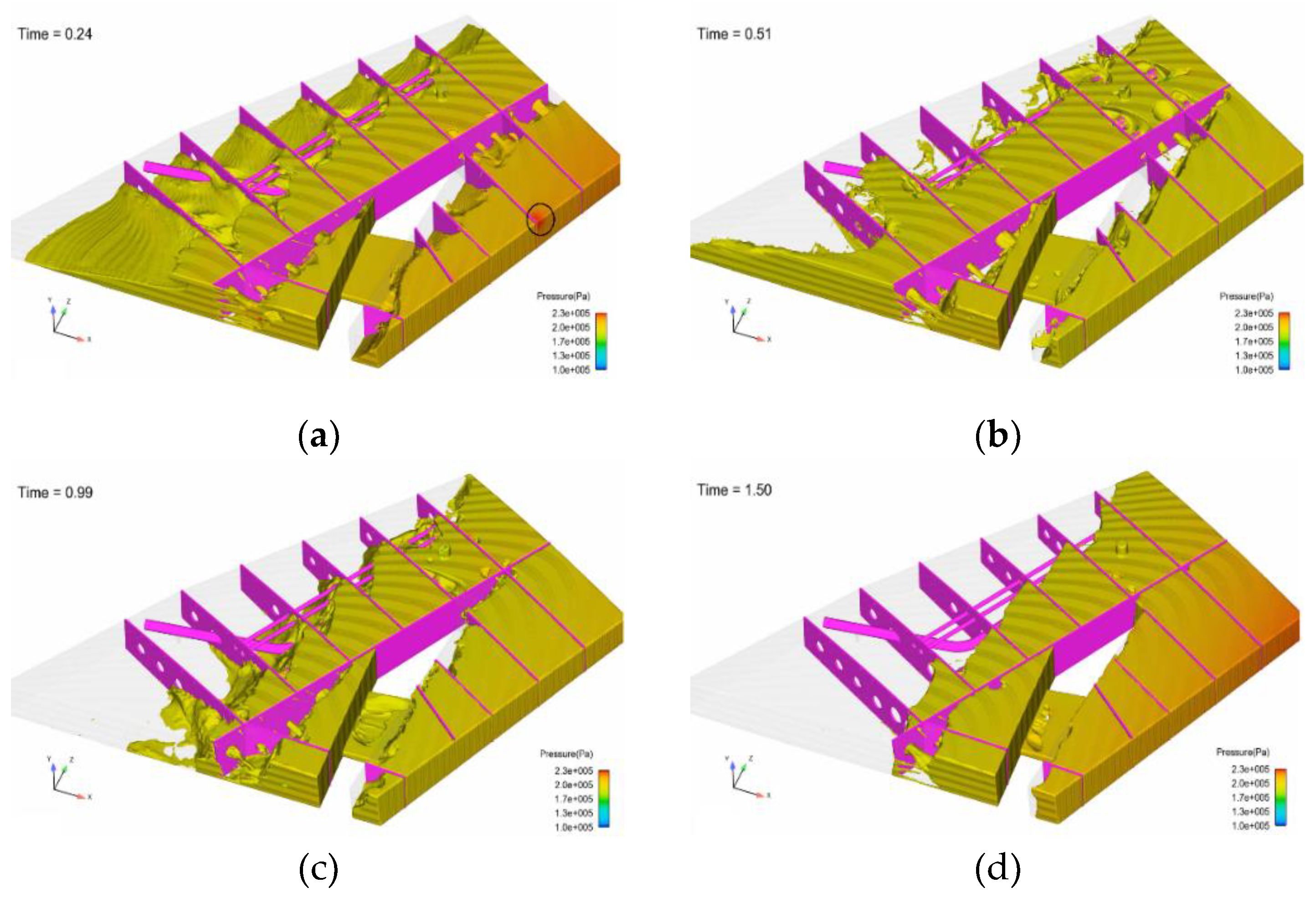
Figure 7 shows the fuel pressure field at a typical moment during aircraft maneuvering. From a macro perspective, due to the continuous compression caused by the incompressibility of fuel, there is a large pressure on the fuel tank wall. At the beginning of the maneuver, the aircraft's yaw acceleration rapidly increases, causing the fuel to move towards the rear of the aircraft, and the resulting "water leap" or "traveling wave" causes impact pressure on the internal baffles and fuel tank wall panels. The internal crossbeams and longitudinal walls increase the damping of fuel movement, hindering large-scale movement of fuel. In addition, the flow resistance generated by the connecting holes on the baffles dissipates the kinetic energy induced by acceleration, so the fuel does not produce a large impact force on the fuel tank wall panels during movement. In areas where high pressure is generated locally, such as the intersection of the rear crossbeam and upper wall panel marked by the circular area, the maximum fuel pressure is about 2.3×10⁵Pa. At t=1.5s, the aircraft acceleration reaches its maximum value, and the corresponding maximum impact pressure appears, with the maximum pressure position on the fuel tank rear wall panel and the right side panel. After t=1.5s, the aircraft's yaw acceleration gradually decreases, and under the influence of inertia, the fuel surges towards the flight direction, and the stress on the fuel tank wall panels gradually becomes uniform.
2.4. Analysis of Fuel Velocity Field Characteristics
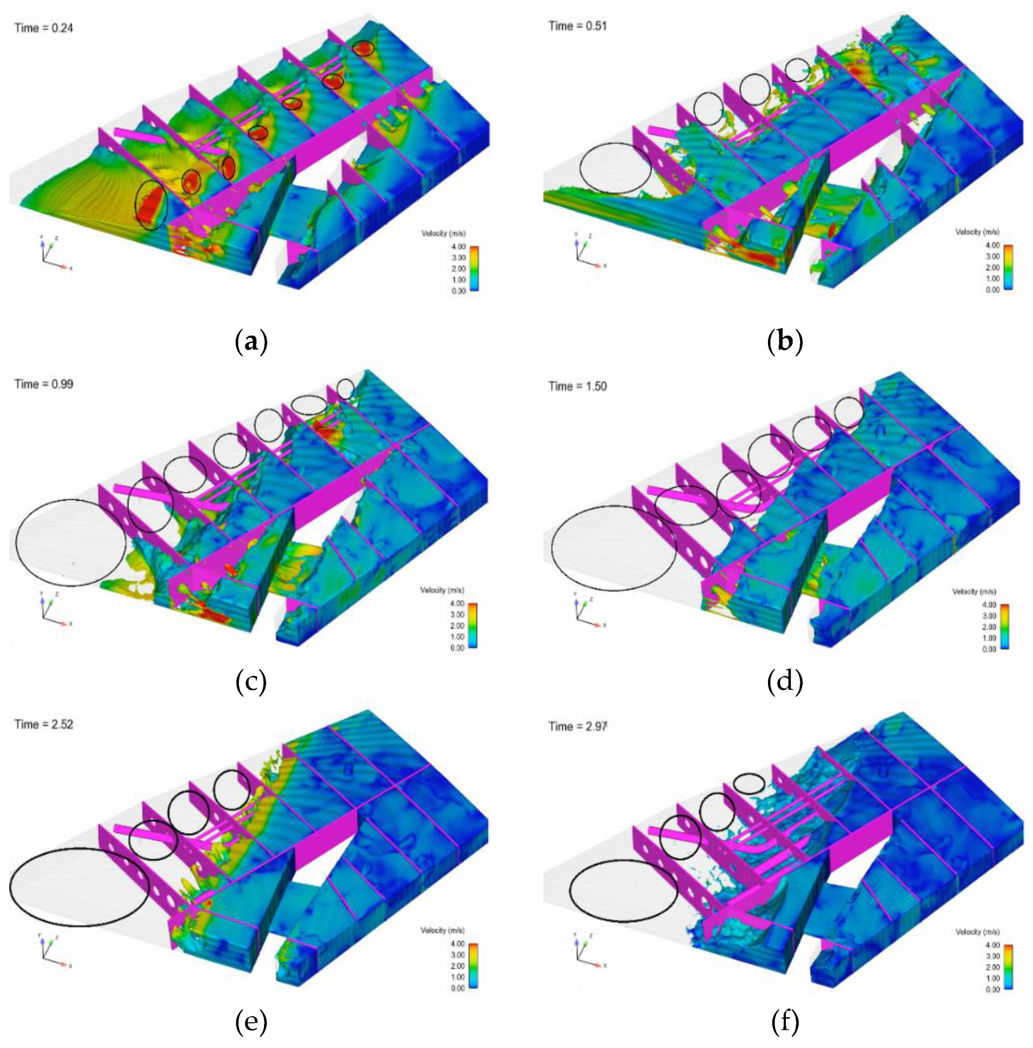
Figure 8 shows a speed field segment of the fuel free surface during the maneuver process, from relative calmness to significant motion. Overall, the flow field inside the fuel tank is relatively turbulent, and the fuel will impact the upper wall of the tank during motion, resulting in a "sloshing" phenomenon; the free surface appears as a steep slope for a period of time. In the initial stage of the maneuver, the fuel tends to gather and move backward. Due to the inertial effect, under the combined action of acceleration and pitch coupling, the free surface exhibits significant stratification, and the fuel velocity decreases rapidly at the flow-through holes of the transverse bulkhead and longitudinal walls. At t=0.51s, due to the superposition of the fuel inertia in the early stage, the free surface phenomenon becomes more complex, with significant surface fragmentation; the fuel at the circular marker inside the compartment moves backward and fills the tail, forming an oil-free zone. By t=0.99s, the oil-free zone expands, and almost all the fuel in the front moves backward. After t=1.5s, the fuel free surface exhibits significant fragmentation.
3. Conclusions
Based on the simulation analysis of fuel movement characteristics in a typical flat fuel tank during aircraft maneuvering, the following conclusions can be drawn:
The feasibility and effectiveness of the finite point set method in simulating the free liquid surface motion of fuel have been verified, and the simulation method can be extended to the study of free surface characteristics of fuel tanks in other aircraft models.
Complex phenomena such as fluctuation, surge, rolling, and fragmentation of the fuel free surface during aircraft maneuvering have been captured, as well as the resulting changes in fuel center of gravity, which can serve as a basis for assessing the safety of aircraft center of gravity.
The fuel velocity attenuation through the connecting holes of the internal baffle in the fuel tank is relatively rapid, and the flow resistance caused by the connecting holes buffers the impact of the fuel on the tank wall.
This work only analyzes the motion characteristics of fuel under the influence of aircraft heading acceleration and pitch, but in reality, the aircraft's maneuvering process may also include parameters such as roll acceleration and angular acceleration. These parameters will undoubtedly have an impact on the fuel motion inside the fuel tank. Therefore, in future research, the effects of roll acceleration and angular acceleration will be incorporated to comprehensively analyze and study the motion characteristics of fuel under the combined influence of multiple excitation factors.
Author Contributions
Conceptualization, Yameng Wang and Song Lu; methodology, Yameng Wang.; software, Yameng Wang; validation, Yameng Wang; formal analysis, Yameng Wang, Chenran Ruan; resources, Zhenghong Li; writing—original draft preparation, Yameng Wang; writing—review and editing, Chenran Ruan; visualization, Chenran Ruan; supervision, Song Lu; project administration, Zhenghong Li; funding acquisition, Song Lu. All authors have read and agreed to the published version of the manuscript.
Funding
This research was funded by Civil Aircraft Scientific Research Project of the Ministry of Industry and Information Technology (BB2320000048, DD2320009001), the Fundamental Research Funds for the Central Universities under Grant No. WK2320000046, WK2320000049.
Acknowledgments
We thank the Supercomputing Center of the University of Science and Technology of China for providing the computing resources and guidance on computational methods.
Conflicts of Interest
The authors declare no conflict of interest.
References
- Bass R L, Bowles E B, Cox P A. Liquid Dynamic Loads in LNG Cargo Tanks [J]. Society of Naval Architects and Ma-rine Engineers, 1980, 88(6): 103-126.
- EIOraheb M, Wagner P. Vibration of a Liquid with a Free Surface in a Spinning Spherical Tank [J]. Journal of Sound and Vibration, 1981, 76(1): 83-93.
- Shageer H, Tao G. Modeling and Adaptive Control of Space-craft with Fuel Slosh: Overview and Case Studies [A].AIAA: 2007-6434, 2007.
- LUCY L B. A numerical approach to testing of the fission hypothesis[J]. Astronomical Journal, 1977,82(12): 1013-1024.
- GINGOLD R A, MONAGHAN J J. Smoothed particle hydrodynamics: Theory and application to no-spherical stars[J]. Monthly Notices of the Royal Astronomical Society, 1977, 181(5): 375-398.
- Yang X F, Peng S L, Liu M B.A new kernel function for SPH with applications to free surface flows[J]. Applied Mathematical Modelling,2014,38(15-16):3822-3833.
- Feng D L, Liu M B, Li H Q, et al. Smoothed particle hydrodynamics modeling of linear shaped charge with jet formation and penetration effects[J].Computers &Fluids,2013,86(5):77-85.
- LIU Mou-bin, ZONG Zhi, CHANG Jian-zhong. Developments and applications of smoothed particle hydrodynamics [J]. Advances in Mechanics, 2011, 41(2): 217-234.
- ONATE E,IDELSOHN S,ZIENKIEWICZ O,et al. A finite point method in computational mechanics: applications to convective transport and fluid flow[J].International Journal for Numerical Methods in Engineering,1996,39(22):3839-3866.
- WANG L,XIE H,ZHANG L. Analysis of fuel sloshing in UAV launching process[J].Aeronautical Science &Technology,2016,27(1):36-40(in Chinese).
- YANG S L,CHEN X F,DU F X. Coupling Dynamics Analysis of Aircraft Fuel Tank Sloshing Fluid and Solid under Maneuvering Behavior [J]. Journal of Aeronautics. 2019, 40(3): 13.
- YANG R. Research of fuel sloshing in aircraft integral tanks by the ALE finite element method[D]. Harbin: Harbin Institute of Technology,2016(in Chinese).
- LIU F,TONG M B,ZHAO H T. Dynamic analysis of liquid sloshing in an aircraft auxiliary fuel tank[J].Aero-nautical Computing Technique,2011,41(3):54-56(in Chinese).
- LIU G, LIN Y,GUAN G, et al. Experimental study of sloshing pattern on LNG independent C type tank[J]. Journal of Dalian University of Technology,2017,57(5): 467-475(in Chinese).
|
Disclaimer/Publisher’s Note: The statements, opinions and data contained in all publications are solely those of the individual author(s) and contributor(s) and not of MDPI and/or the editor(s). MDPI and/or the editor(s) disclaim responsibility for any injury to people or property resulting from any ideas, methods, instructions or products referred to in the content. |
© 2023 by the authors. Licensee MDPI, Basel, Switzerland. This article is an open access article distributed under the terms and conditions of the Creative Commons Attribution (CC BY) license (http://creativecommons.org/licenses/by/4.0/).

