1. Introduction
Friction Stir Welding (FSW) was patented at The Welding Institute (TWI) in the UK. Since its invention in 1991, a significant development effort has been conducted to adapt this process in order to make it suitable for welding various materials and geometries, in different positions and joint types, while providing joints with reduced or eliminated imperfections and defects [
1,
2,
3,
4,
5] The developments thus went into several directions, reaching rather complex kinematic patterns (Reverse dual-rotation FSW or Re-stir) and tools (stationary shoulder FSW; semi-stationary shoulder tool FSW), being some examples [
6]. Also, allied technologies emerged: friction stir processing (FSP), channeling/tunnelling (FSC/FST), incremental forming (FSIF), riveting (FSR) and extrusion (FSE), all exploring the same friction-based heating of the material using a tool of optimized geometry and stirring it in order to obtain technological benefits other than welding [
7]. The advantages of well-designed FSW-based processes are solid joints without pores and cracks, lower distortion and shrinkage, superior mechanical properties compared to fusion-based processes, particularly in joining of difficult to weld materials and obtaining dissimilar material welds, no filler, flux or shielding gases are needed, energy efficiency and it is environmentally friendly. Disadvantages encompass high specialized equipment cost, lower flexibility compared to arc welding processes, non-forgeable materials cannot be joined and complex special fixtures including backing plate [
8,
9,
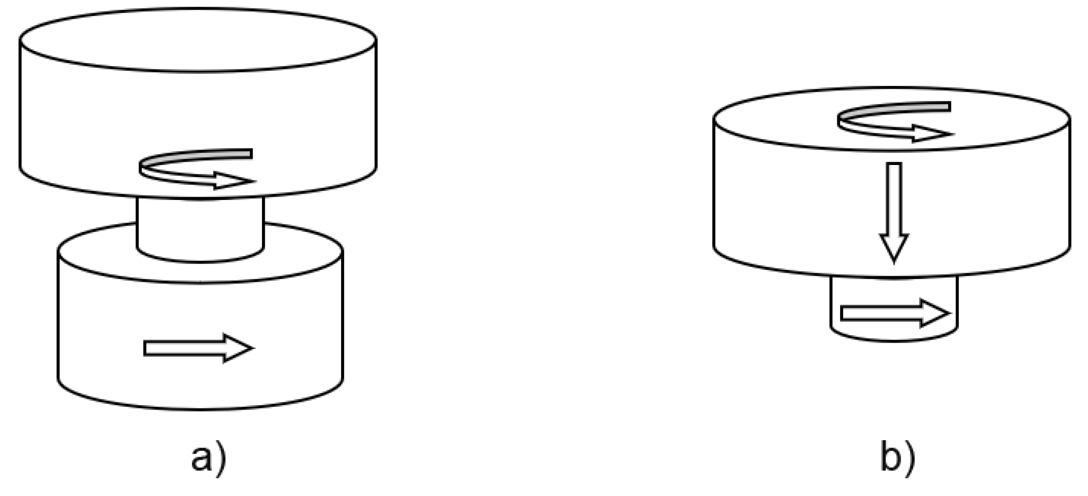
10]. Bobbin tool FSW (BTFSW) was envisaged as a simplified (and thus more reliable) process, using a special two-sided shoulder tool interconnected by a probe (
Figure 1a). Contrary to this, conventional FSW tool utilizes one shoulder and the probe, where the shoulder forms the weld surface, while the pin stirs base materials,
Figure 1b. Two shoulders envelope the base metal from the top and bottom, eliminating the vertical force. This way, root imperfections may also be avoided, theoretically improving bend and fatigue performance of welds [10, 11].
Other advantages of BTFSW were identified as: higher and more balanced heat input with less distortion, successful welding of closed hollow extruded profiles, but also more limited as only open-ended joints can be welded. However, the tool probe experiences tensile, torsion and bending forces significantly higher than those of conventional FSW tool probe, that experiences compression, torsion and bending. Tensile stresses in the probe are highly dependent on the tool geometry and welding parameters, of which interference can be viewed as an equivalent to plunging depth in conventional FSW. Too low interference has a similar effect as a lower plunge depth: a possible insufficient forging effect, friction and heat generation, leaking of the material from the weld zone and possible defects. On the other hand, smaller shoulder gap (too much interference) is the equivalent of a larger plunge depth, generating more friction, heat, but also more flash and stress, leading to a shorter tool life due to probe fracture [
11]. Sued and Pons [
13] reported that a lower plunge depth by using bobbin tool FSW of AA6068-T6 resulted a defect free joint. Also, Suad et al. [
14] welded 4 mm AA6082-T6 by BTFSW and it was found that the medium 3.75% interference was optimal, compared to 0% interference and 8.75% interference. Zhang et al. [
15] applied a probe with three flats, a scrolled shoulder surface profile and a plunge depth of 0.07 mm, to weld 2A14-T6 alloy and reach joint efficiency of 75 %. However, the research gap still exists, as there is a limited number of publications in this, for BTFSW very important area.
In this work, the influence of interference of the square pin tool with convex shoulders, on mechanical properties, including joint efficiency, macro and microstructural features was studied.
2. Materials and Methods
For the purpose of the experimental investigation, AA5005 H32 aluminium-magnesium alloy was used. Chemical composition tested by ARL 3580 (Thermo Scientific, Waltham, USA) optical emission spectrometer (OES) and tensile mechanical properties obtained by ZDM 5/91 (VEB, Leipzig, Germany) tensile testing machine is presented in
Table 1 and
Table 2, respectively.
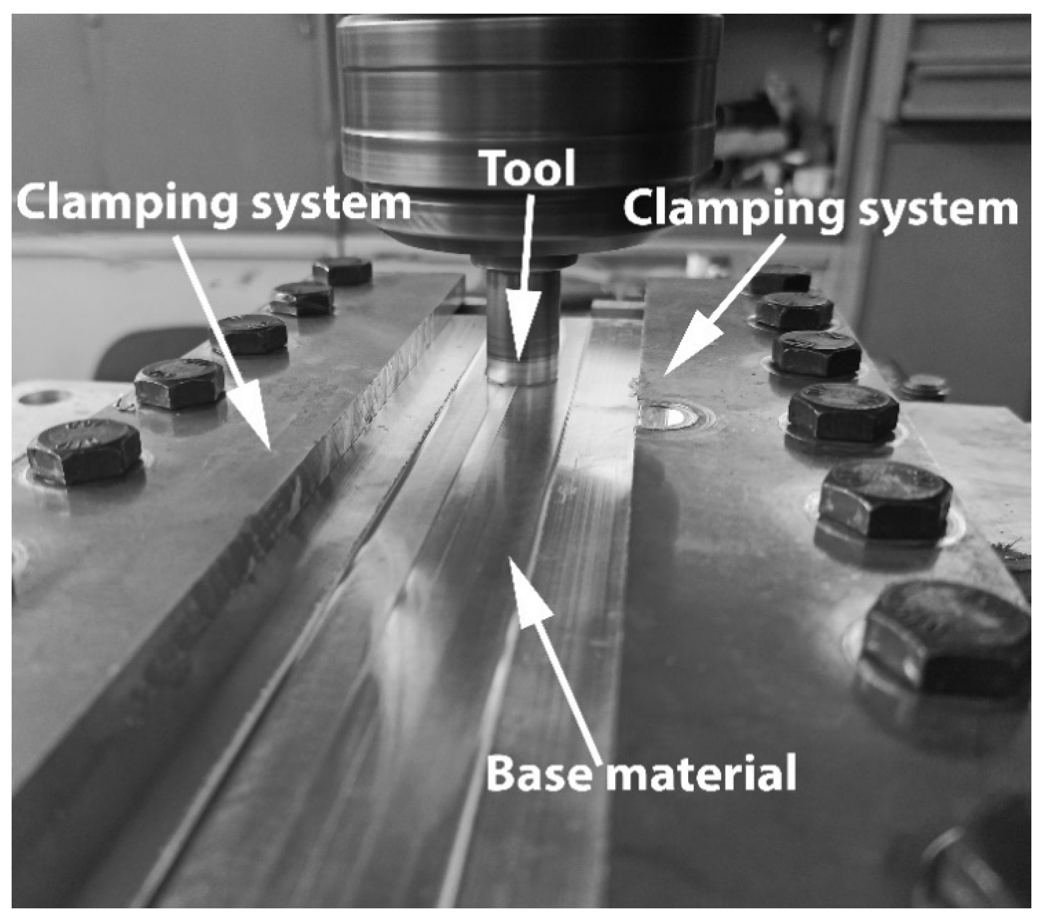
The experimental welding was performed on a FSSGVK-3 (Prvomajska, Zagreb, Croatia) vertical milling machine, with a specially designed fixture (
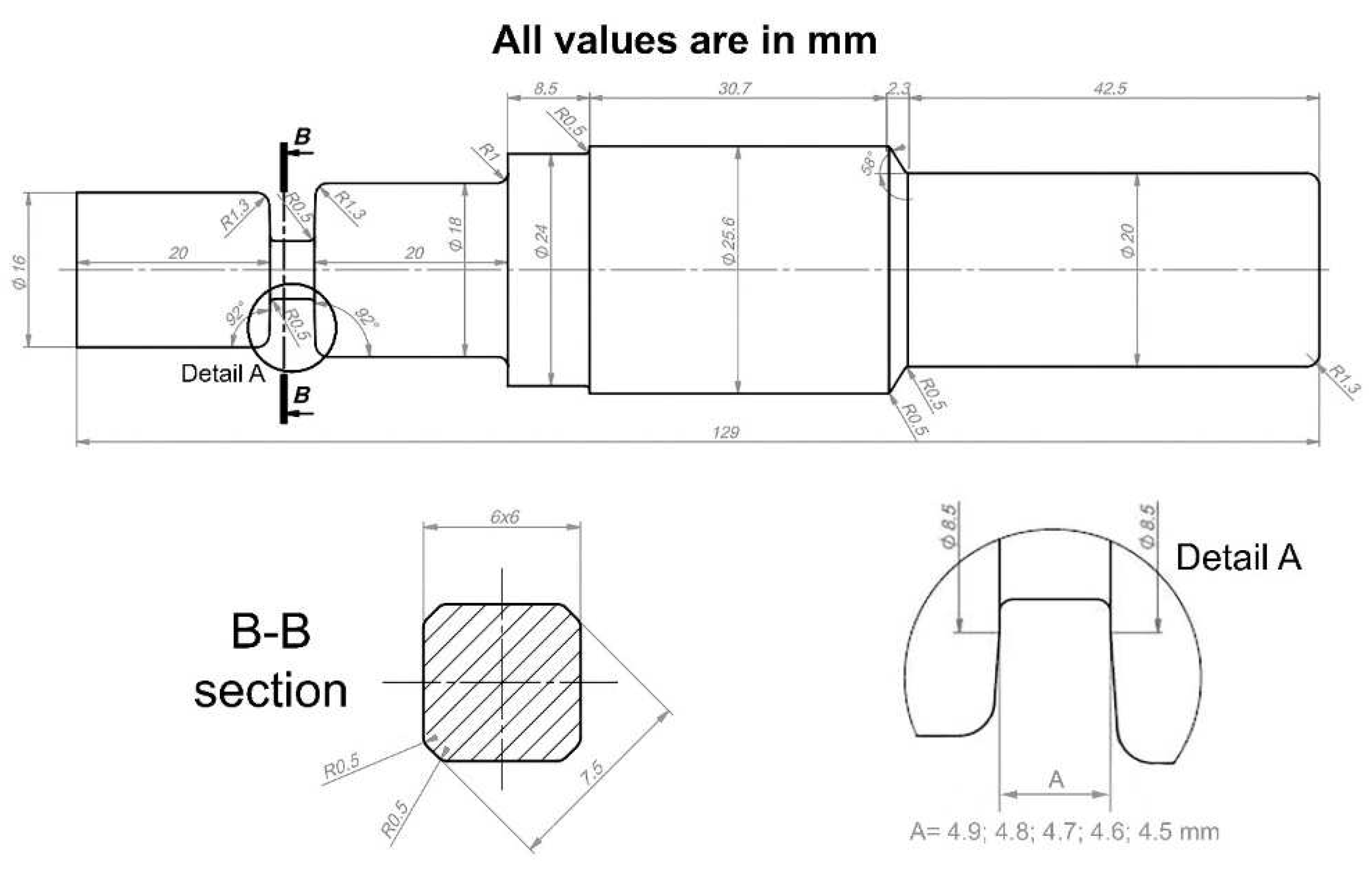
Figure 2) for providing a stable butt-welding conditions of 150 x 60 x 5 mm plates. BTFSW tool temperature was monitored by using the IR camera, TP8S (ThermoPro, Toronto, Canada), with temperature range from – 20°C to 2000°C, accuracy of ± 2°C and coefficient of emissivity of 0.4. The clamping system provided the central groove that allows the passage of the bottom shoulder of the tool without interference. An array of tools was designed, having both shoulders the convex shape with dip angle of 2o, while the pin was of four-sided flat type, with the geometry shown in
Figure 3. Tool geometry was designed to have key working surfaces easily accessible and simple for cleaning (no scrolls as in [
14]), and therefore well suited for industrial use. Tool material was AISI H13 (X40CrMoV5-1) hot-work tool steel, quenched in oil and tempered to 53 HRC. Welding parameters and designation system are given in
Table 3. The distance between tool shoulders was varied, influencing the interference and therefore forging effect within the base material, to find its influence on mechanical properties and microstructural features of welds.
Weld characterization comprised of tensile, bend and impact testing, macro and microstructural analysis was conducted. Tensile testing was performed on VEB ZDM 5/91 (Verkstoffpruefmaschinen, Leipzig, Germany) mechanical tensile testing machine, complying with EN ISO 4136:2012 standard on two specimens. Ultimate tensile strength and cross-section reduction were reported, as well as joint efficiencies. Charpy impact test was performed on JWT-450 (Jinan, Jinan, China) instrumented tester at room temperature, in accordance with EN ISO 148-1:2016 standard on two specimens. V-notch was machined so that the crack initiation and propagation passed through the nugget zone (NZ). Bend testing was also done on VEB ZDM 5/91 machine, in accordance with EN ISO 5173:2009 standard. It was performed on four specimens, two bent one over the top, the other over the bottom of the weld. Bending was conducted until a crack appeared on the surface of the sample and the average angle was reported. Afterwards, the testing continued until fracture, or until reaching the full 180°.
Standard metallographic preparation was done, comprising of grinding with SiC abrasive papers (220 to 2500 grit), polishing with diamond suspension (6, 3, 1 and ¼ µm diamond particles) and OP-S colloidal silica suspension. Etching was performed by using anodic oxidation process in Barker’s reagent (5 ml HBF4 + 200ml distilled water). Welds were examined by using Leitz Orthoplan (Leica, Wetzlar, Germany) light microscope under polarized light. Grain size was determined by comparison procedure, using ASTM E112 standard. Fracture surfaces were assessed by JEOL JSM-6460LV scanning electron microscope (SEM) operating at 20 kV, while energy dispersive X-ray analysis was done by using Oxford Instruments INCA microanalysis systems. Mechanical testing results were correlated to macro, micro examination, including grain size, as well as maximal tool temperatures obtained from thermograms.
Furthermore, the fractured tool was metallographically characterized, after a standard preparation in Struers laboratory, 3 % Nital etching and light microscope and SEM analysis.
3. Results
3.1. Thermograms
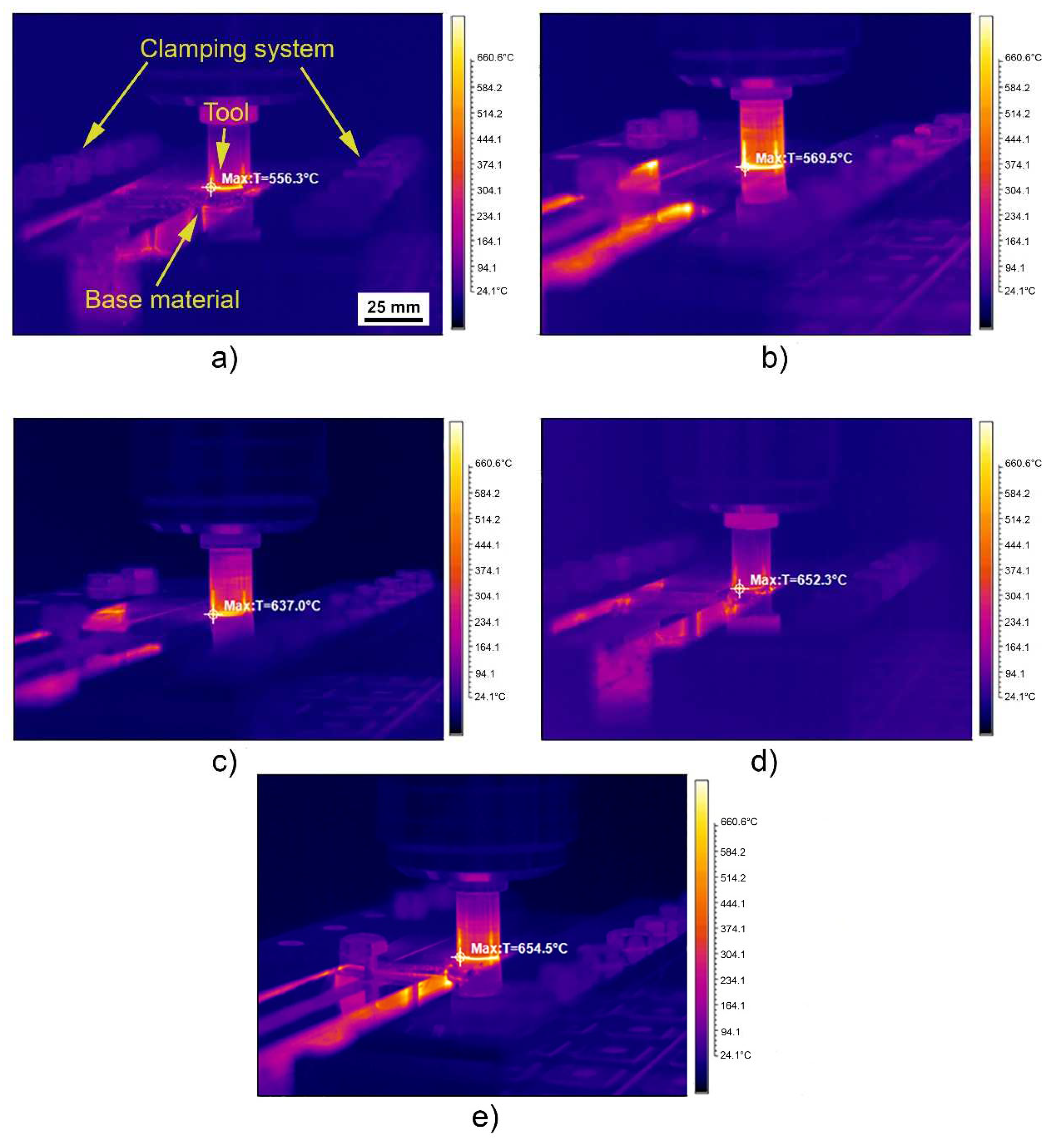
Thermograms of the BTFSW tool are shown in
Figure 4. As can be seen, the maximal measured temperatures are on the tool near to the base material. In some specimens, the tool surroundings show relatively high temperatures, higher than the actual ones, due to the highly reflective aluminium surface. Maximal temperature was measured in the tool providing the highest interference between the top shoulder and base metal (
Figure 4e). This is due to the highest pressure in the material induced by BTFSW tool shoulders.
3.2. Metallographic Testing Results
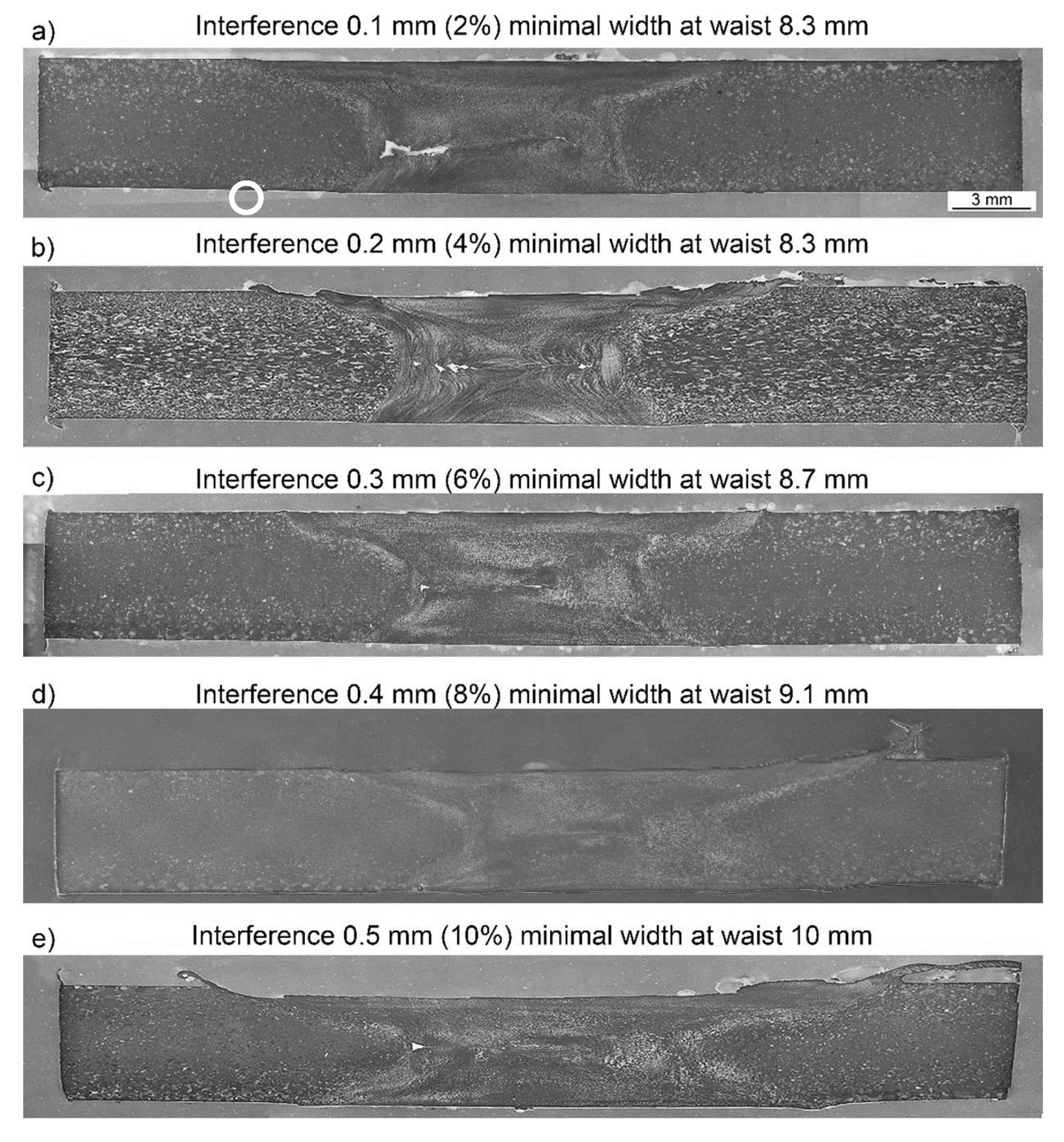
Macro cross-sections of welds obtained with different interferences are shown in
Figure 5. A higher interference causes a more pronounced flash to occur. It can be seen that wormhole defect (ISO 6520-1 reference number 200) is present in all specimens except Specimen 4 with interference of 0.4 mm. The wormhole defects occur within the waist formed by the tool (thermomechanically affected zone/nugget zone), towards advancing side (AS). In Specimen 1, with the highest interference, the wormhole protrudes into the nugget. In Specimen 2, multiple wormholes are observed, some also within the nugget. This can be viewed as a transition towards a single triangular wormhole combined with a narrow crack-like one in Specimen 3. In Specimen 5, a single triangular wormhole is present. Maximal wormhole dimensions are shown in Table 4, as well as the compliance with ISO 25239-5 standard [
16]. That means, the applied technology, comprising of the tool geometry and welding kinematic parameters can be utilized to obtain BTFSW welds that fully comply with acceptance level B (Specimen 4) and acceptance level C (Specimens 3 and 5).
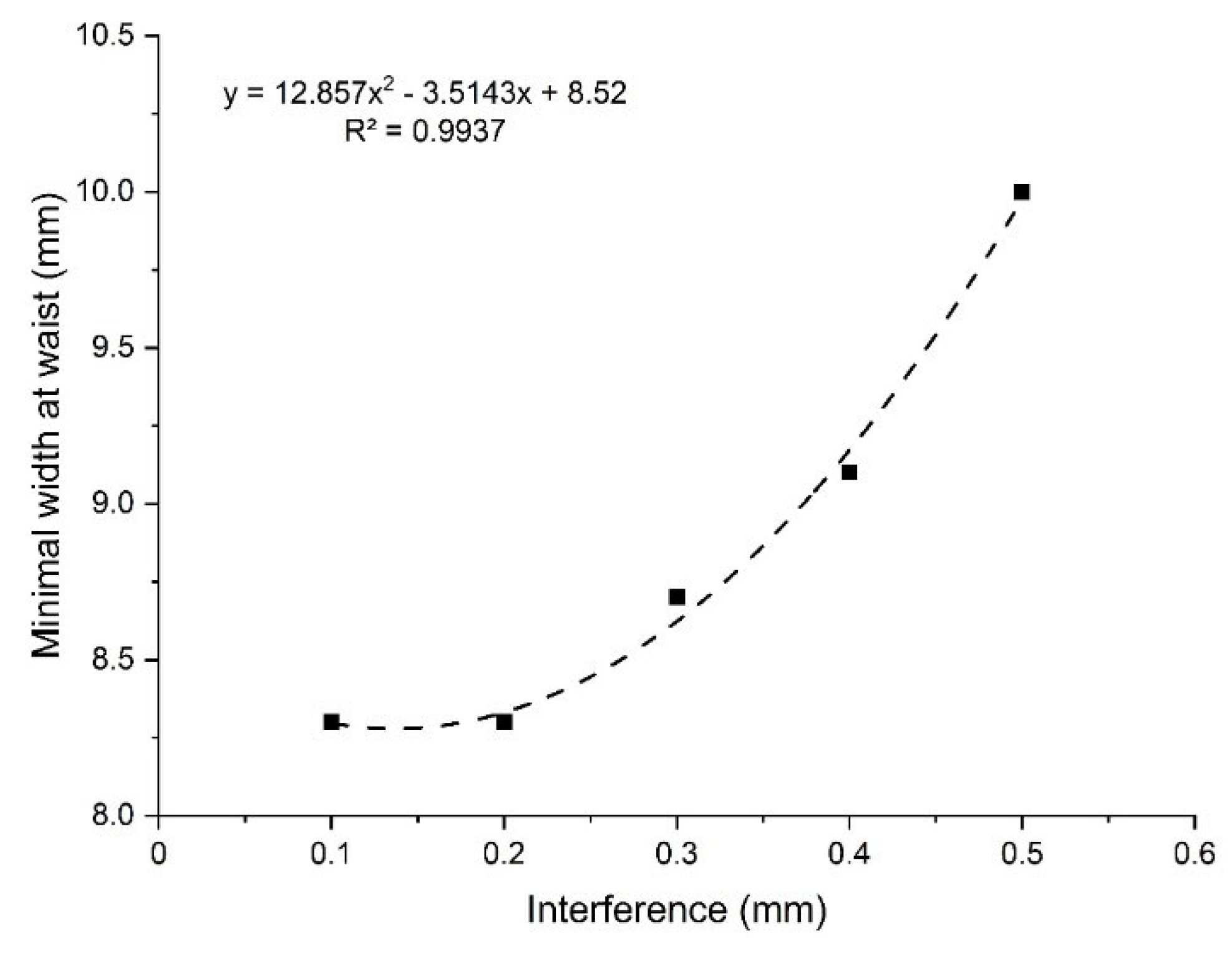
A higher interference influences a rise in the maximum temperature of the tool due to an increased friction. A higher temperature softens the material more intensively, causing a rise in minimal width at waist in macro images (minimal distance between TMAZ-AS/HAZ interface to TMAZ-RS/HAZ interface),
Figure 5. The dependence of minimal width at waist from interference is shown in
Figure 6. The obtained coefficient of determination of the fitted curve R
2=0.99374 is relatively high, proving that the proposed fitting regression quadratic polynomial function line approximates the actual data well, for the purpose of interpolation. The trend of width at waist (in relation to interference induced maximal process temperature) behaves similarly to the width of NZ and TMAZ zones (in relation to tool rotation speed induced process temperature) in friction stir spot welded Al-Mg specimens obtained in [
17].
In Specimen 1, with the lowest interference, the minimal width at waist is just slightly higher than the maximal dimension of the pin (7.5 mm,
Figure 2). As the interference is decreased, the stir zone becomes more cylindrical. An increased interference and subsequent increased tool temperature inevitably increase stresses in the material and potentially reduce tool life.
Table 5.
Wormhole dimensions and compliance with ISO 25239-5 standard.
Table 5.
Wormhole dimensions and compliance with ISO 25239-5 standard.
| |
Cavity width x height mm |
Acceptance level - ISO 25239-5 standard |
| Specimen 1 |
2.48 × 0.8 |
Not compliant |
| Specimen 2 |
2.37 × 0.27; 0.03 × 0.03 |
Not compliant |
| Specimen 3 |
0.04 × 0.04; 0.07 × 0.01 |
C |
| Specimen 4 |
0 |
B |
| Specimen 5 |
0.04 × 0.4 |
C |
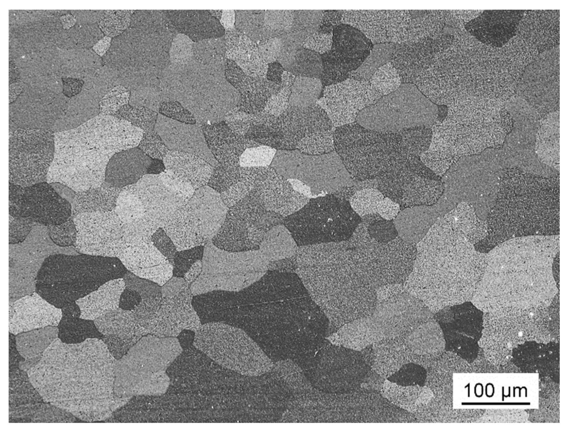
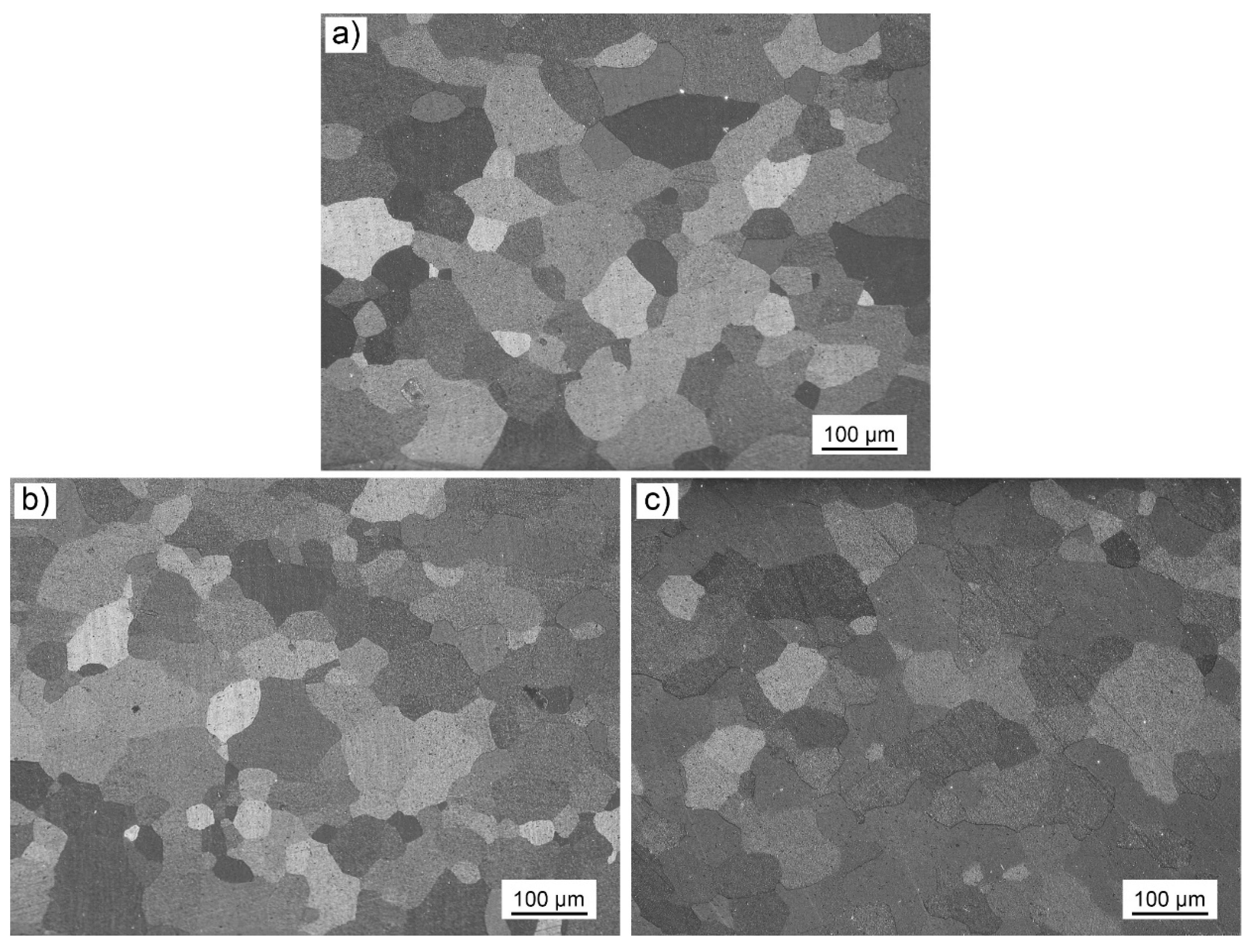
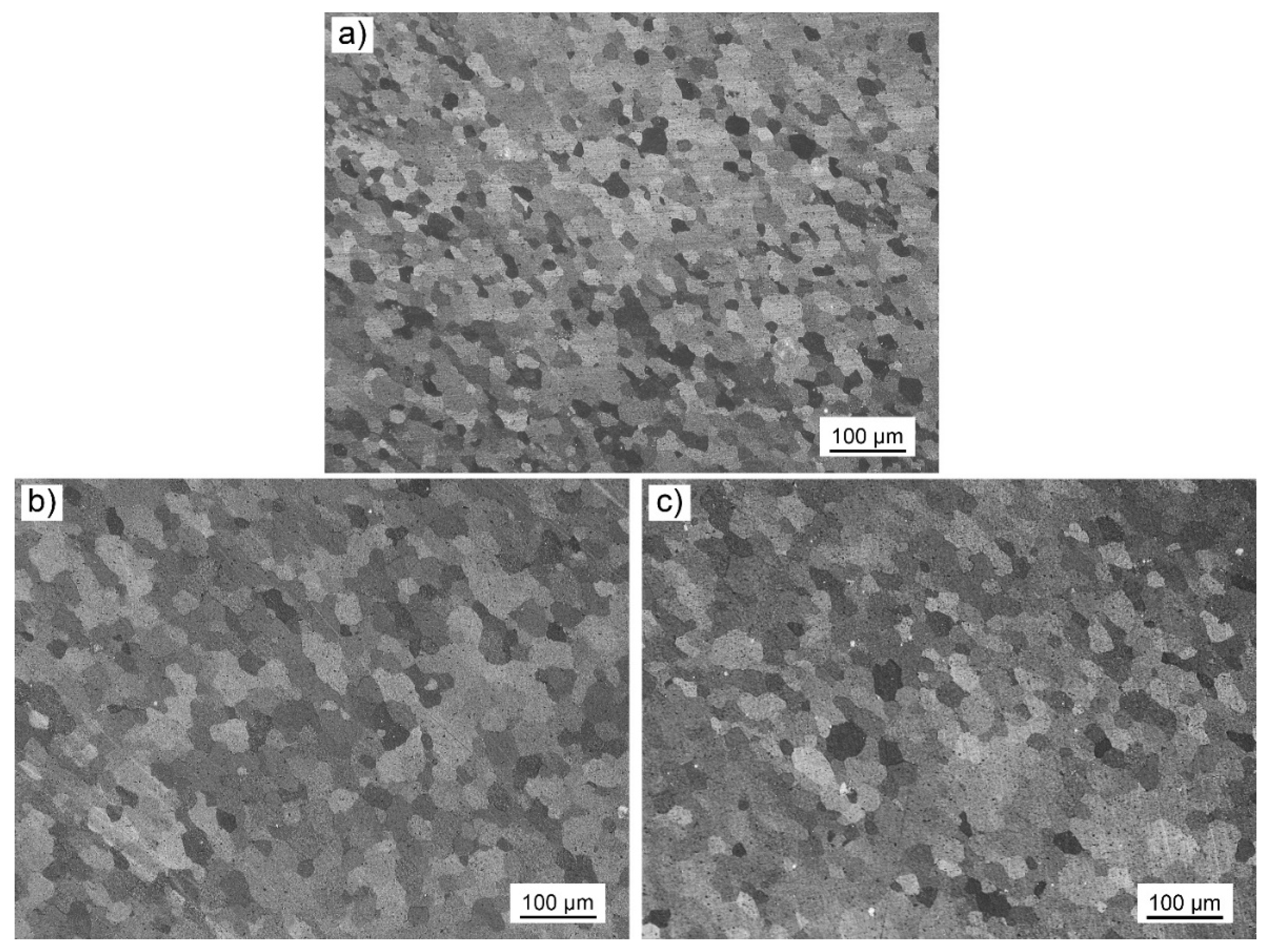
Metallographic images of the base material, HAZ and nugget are shown in
Figure 7,
Figure 8 and
Figure 9. HAZ and nugget microstructures were reported for the most representative specimens, such as Specimen 1 (the lowest interference), Specimen 4 (optimal) and 5 (the highest interferences). White circle and square in
Figure 5a indicate the position where HAZ and nugget microstructures in
Figure 8 and
Figure 9 were taken. Average grain size in these zones is shown in
Table 7. Base metal consists of uniaxial grains with an average size of 4.5. In the nugget zone, as the interference is higher, the grains are coarser, due to a higher heat generated by a more pronounced interference between the tool shoulder pinching gap and the thickness of the base metal, as shown by the listed thermograms in
Figure 4. This implies that a higher temperature generated during the BTFSW process overcomes a higher deformation, that is, the squeezing effect on the base metal induced by the tool.
3.3. Tensile Testing Results
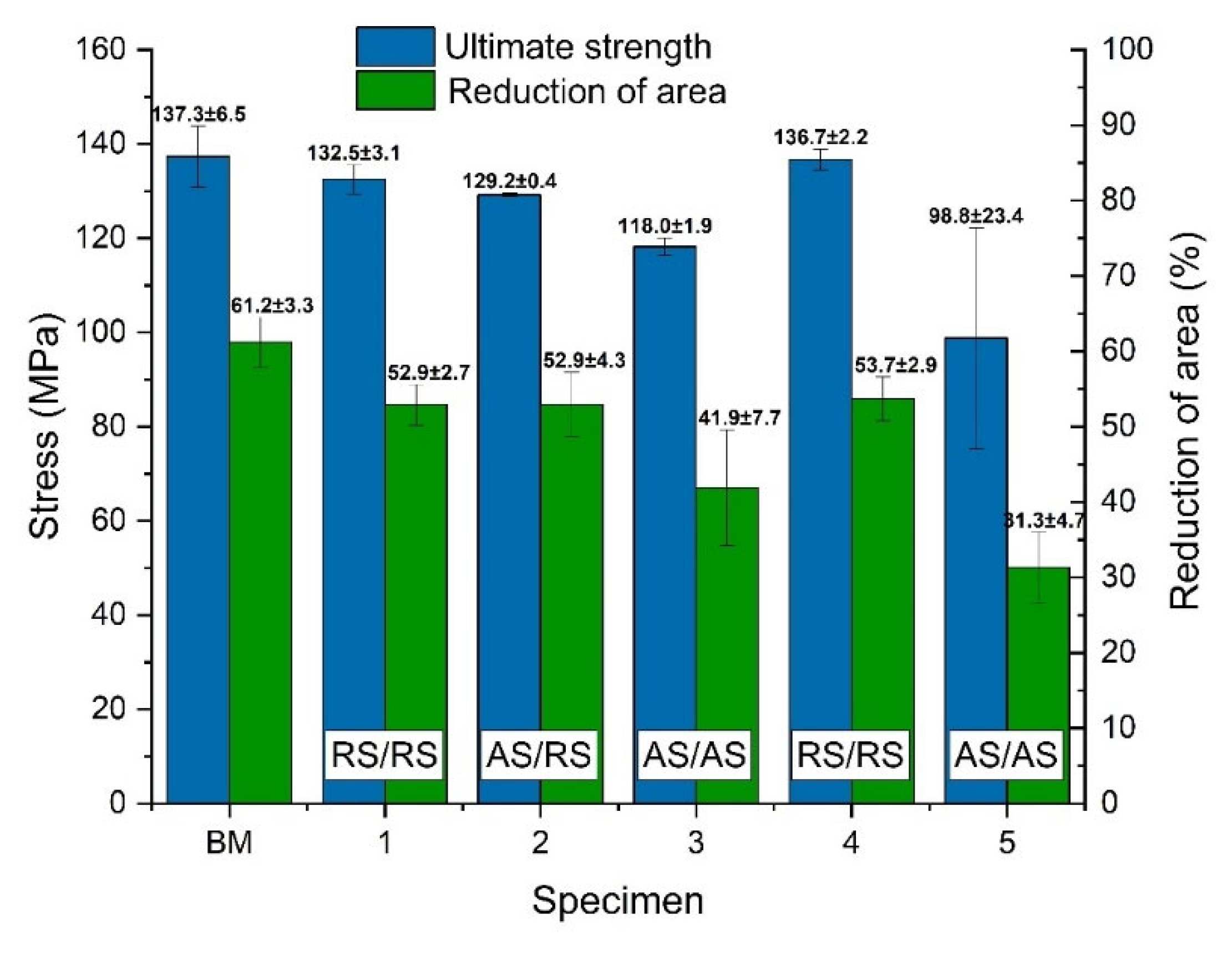
Tensile testing results are shown in
Figure 10. The highest tensile strength was obtained in Specimen 4, which can be attributed to the absence of wormhole defect. A lower interference results in a lower peak temperature and therefore, a less pronounced grain coarsening in the HAZ (Specimens 1 - 3). On the other hand, an increased interference induced elevated welding temperatures, which caused grain coarsening effect in the HAZ, which, along with the presence of wormhole defect results in a relatively low tensile strength (Specimen 5). These results are in accordance to the results by Labus-Zlatanovic et al. [
18], who found that a higher heat input in FSSW resulted in a coarser grain size in the NZ. This effect has a significant influence on mechanical properties, where a coarser grain resulted in a lower small punch test rupture load.
The largest wormhole defect in Specimen 1 is compensated by two effects: the first is the effect of a finer grain in Specimen 1, while the other is the longitudinal orientation of the wormhole, which apparently has a minor influence on tensile properties. The effect of the wormhole defect is evident in location of fracture, which occurred in AS, which is in contrast to the common fracture location in RS in FSW Specimen 4 [
7,
19,
20]. A similar trend can be observed in terms of reduction of area, with maximal values obtained in Specimen 4. Tensile strength and reduction of area of the Specimen 4 are just under the nominal values of the base metal, rendering the strength weld effectiveness and reduction weld effectiveness to be a relatively high 97 and 88 %, marginally lower than that of the base metal.
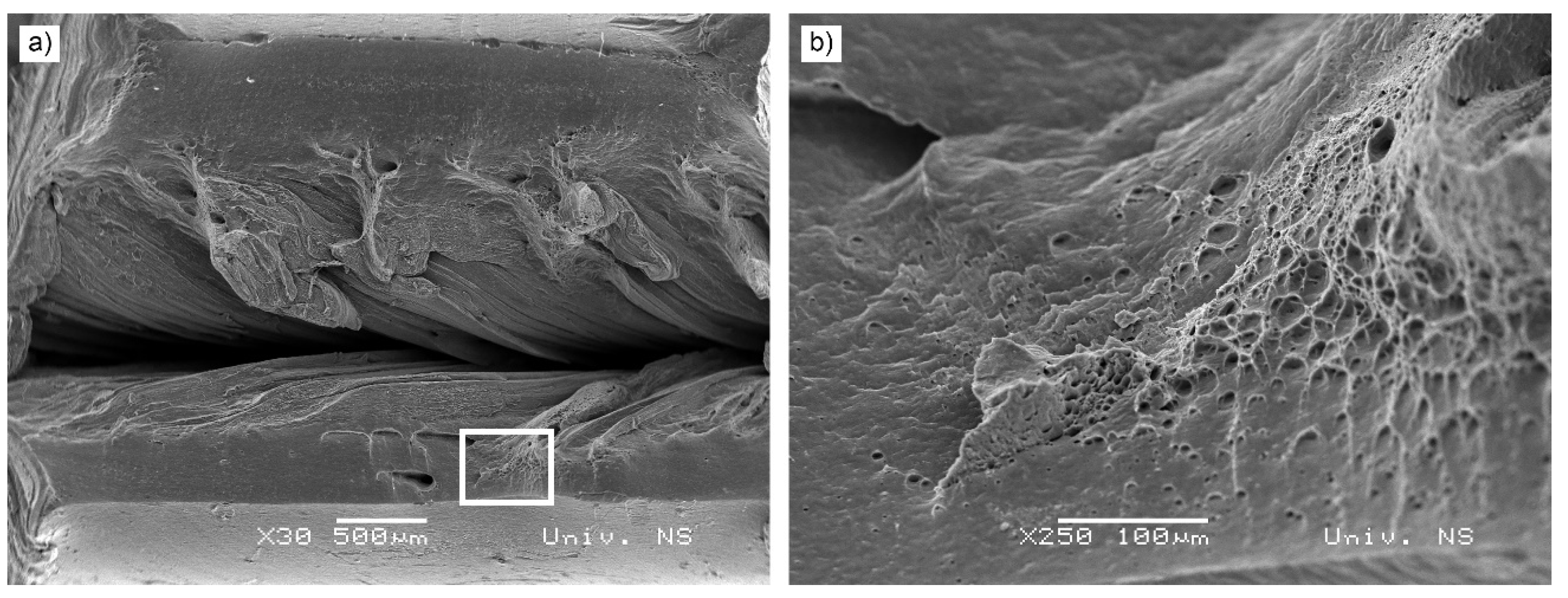
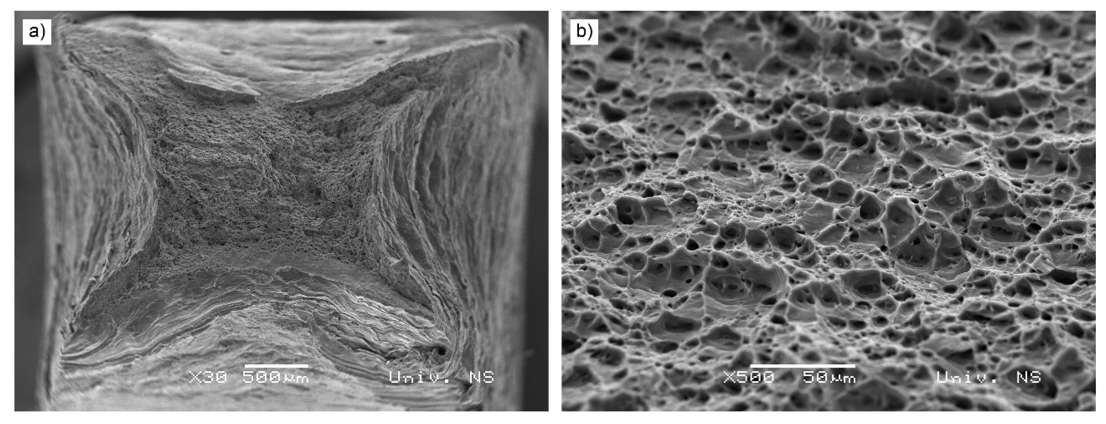
Fracture surfaces of specimens 1 and 4 are shown in
Figure 11 and
Figure 12. In Specimen 1, a significant plastic deformation can be observed, particularly at the edges of the fractured surface and around wormhole forms in the central-lower part of the specimen,
Figure 11. Also, a quasi-cleavage fracture mode is present, exhibiting both cleavage and plastic deformation with clearly visible dimples. A very fine dimpled fracture surface, but without wormhole is present in Specimen 4,
Figure 12. A characteristic X-shaped fracture can be observed, common in square cross-section tensile tested specimen. Reduction of area in Specimens 1 and 4 are similar, however, it is apparent that the dimples are finer in Specimen 1, which is in accordance with the results of metallographic tests,
Table 6. A wave-like morphology in the wormhole region obtained in Specimen 1 is most probably the result of stirring effect by the probe, where the waves represent the incremental material addition by the probe sides.
3.4. Impact Energy Testing Results
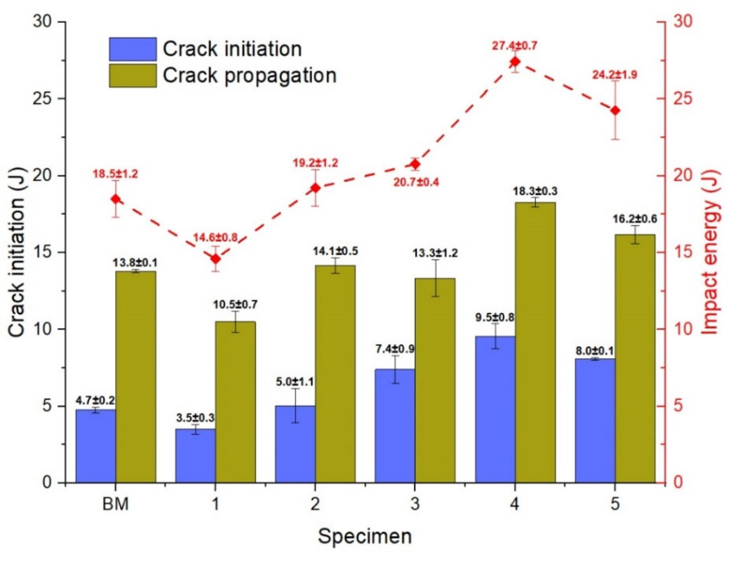
Impact energy testing results are shown in
Figure 13. The highest crack initiation, crack propagation and the sum of them, impact energy was obtained in Specimen 4, which replicates the results of tensile testing. This is the effect of the absence of wormhole, unlike other specimens, particularly 1, 2 and 3, where there is a considerable drop in these values due to the centrally located wormhole (Specimen 1) or wormholes (Specimens 2 and 3). In Specimen 5, slightly lower values compared to Specimen 4 were obtained. This can be attributed to a marginally coarser grain in the nugget zone, as the result of a higher process temperature. As the wormhole in this specimen is placed not directly in the central weld zone, it can be assumed that its effect on impact energies is minor.
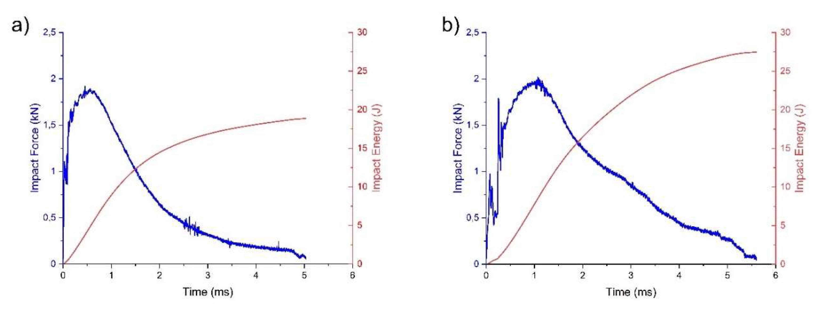
Compared to base metal, impact energy effectiveness’s in Specimen 4 are: 101, 33 and 48 % higher, if crack initiation, crack propagation and impact energy are considered, respectively. The main effect is the grain refinement in the nugget zone compared to base metal, without the presence of wormhole defect. This can be illustrated by the shape of the impact force versus fracture time curves,
Figure 14. Specimen 5, compared to base metal has a considerably higher and longer chart, indicating that the maximal force is higher, as well as the duration of the fracture is longer. On the other, hand, all trends in terms of crack initiation to crack propagation energies, where the latter are higher, are the same as in base metal.
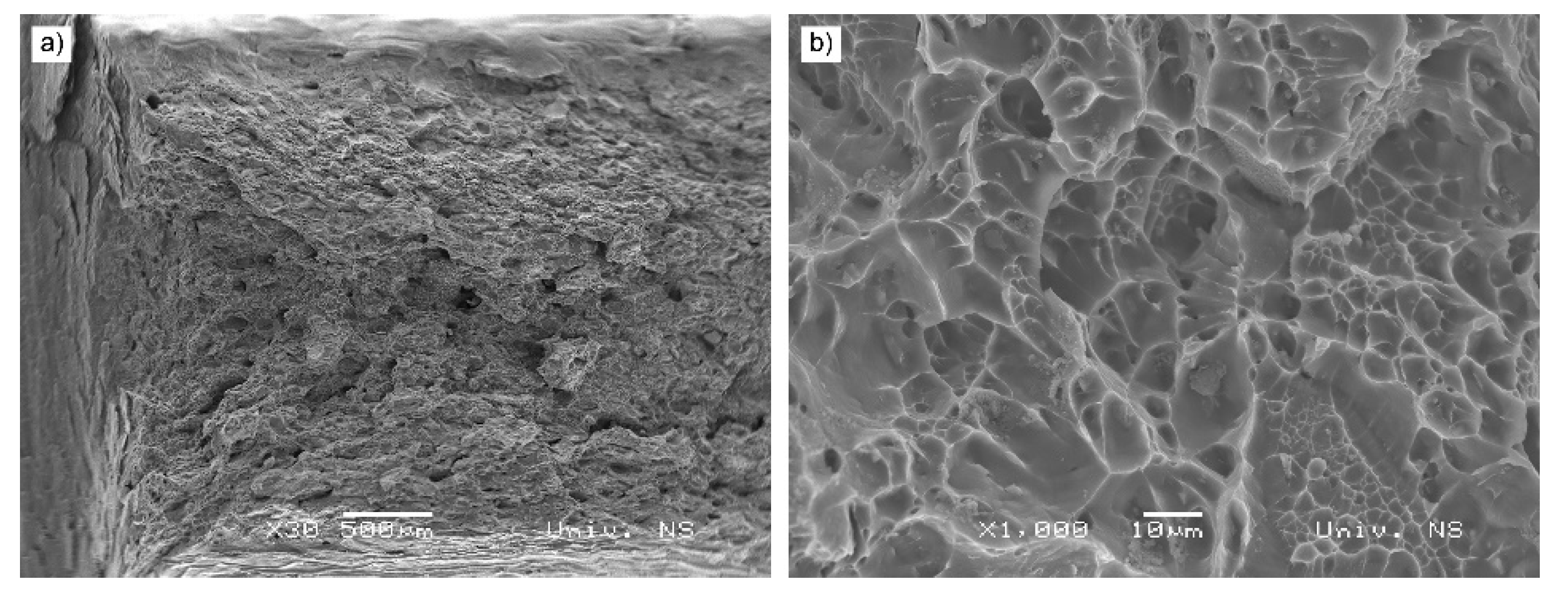
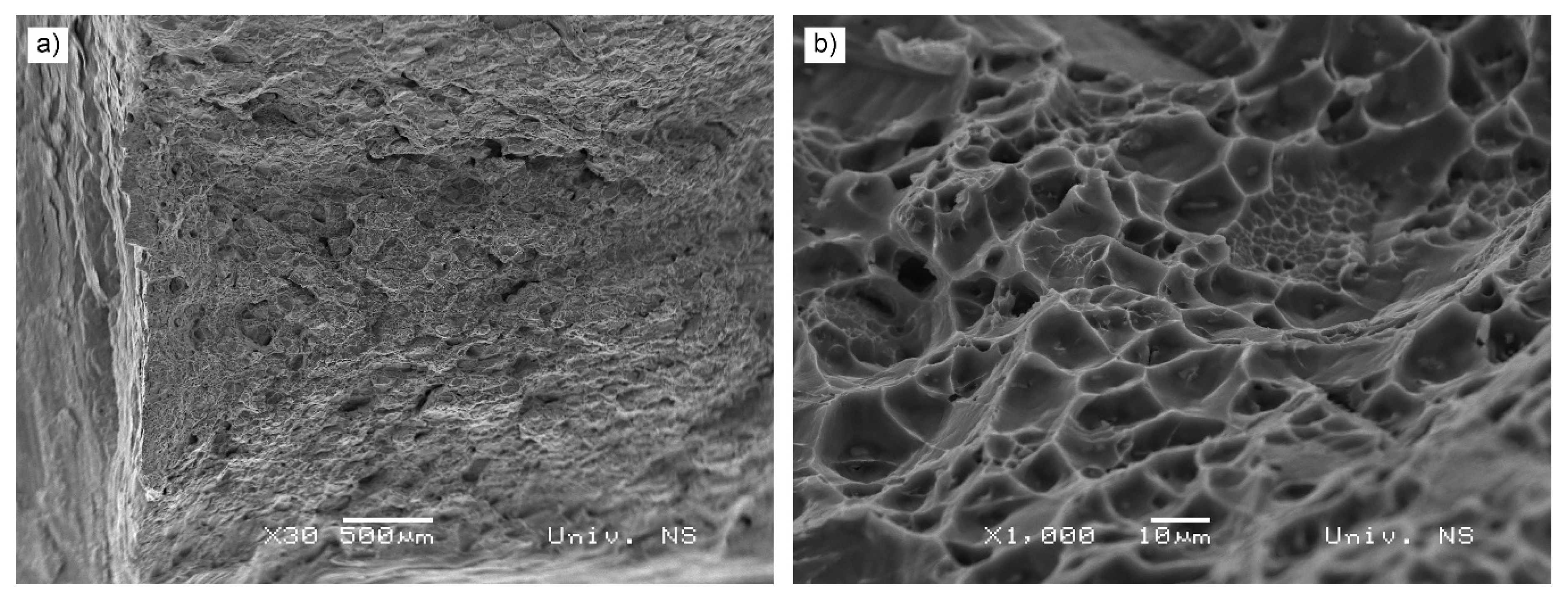
The fracture surfaces of Specimens 1 and 4 are shown in
Figure 15 and
Figure 16. A similar dimpled fracture surfaces were obtained, however, as in
Figure 11 and
Figure 12, a slightly finer dimples were observed in Specimen 1. This can be explained by a lower processing temperature.
3.5. Bend Testing
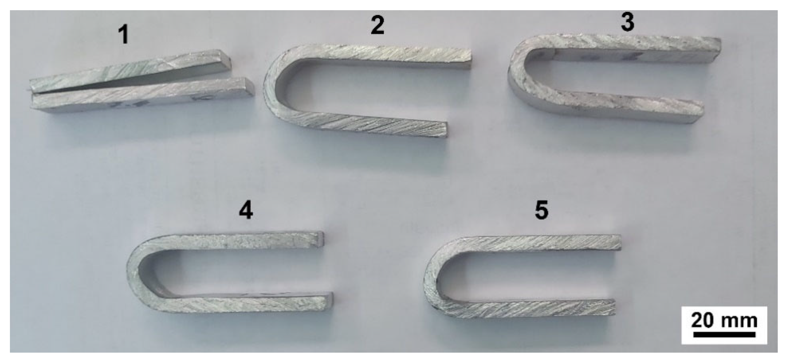
Bend testing results, over the bottom and top shoulder formed surface, are shown in
Table 7 and
Figure 17. In Specimens 3 to 5, bent over the weld bottom surface, no cracks occurred. However, in Specimens 1 and 2, cracks occurred, probably as a result of wormholes. Subsequently, all specimens were bent to 180° without fracture, except for Specimen 1. When bent over the top surface, no cracks nor fractures occurred. The main reason for a better performance when bent over the bottom of the welds is the location of long wormhole defects that are closer to the bottom, as was obtained in [
7].
Table 7.
Bend test results.
Table 7.
Bend test results.
| |
Bending over the bottom surface |
Bending over the top surface |
| First crack ° |
Bend Test to 180° |
First crack ° |
Bend Test to 180° |
| Specimen 1 |
13.6 |
Fracture |
None |
No fracture |
| Specimen 2 |
93.1 |
No fracture |
None |
No fracture |
| Specimen 3 |
None |
No fracture |
None |
No fracture |
| Specimen 4 |
None |
No fracture |
None |
No fracture |
| Specimen 5 |
None |
No fracture |
None |
No fracture |
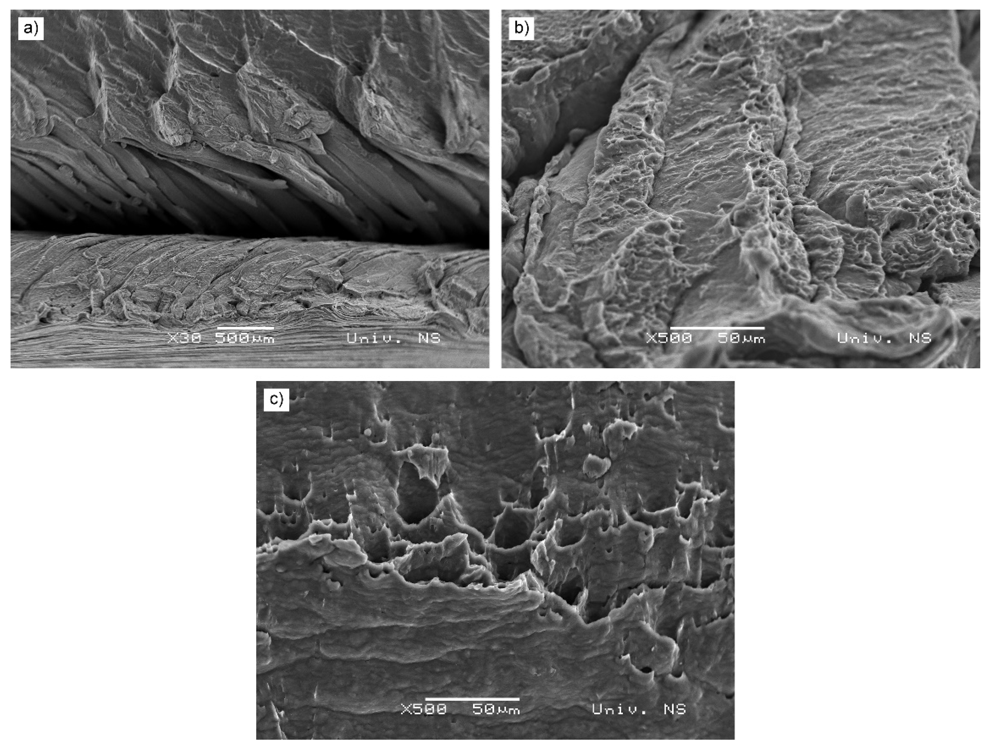
The fracture surface of the bend-tested Specimen 1 is presented in
Figure 18. Similarly to the tensile tested specimen shown in
Figure 11, the wormhole is clearly visible and plays a major role in premature failure. Wave-like morphology of wormhole sides is present as well, which is the result of stirring effect by the probe. The visible wave-like morphology is obtained by incremental material addition by the probe sides during stirring. Also, a quasi-cleavage fracture mode is present, exhibiting both cleavage and plastic deformation with clearly visible dimples, present on both sides of the wormhole,
Figure 18b, c.
4. Conclusions
Based on the results and within the limitations of this study, the following conclusions can be established:
A higher interference between shoulder pinch gap and base metal influences the rise in temperature due to a higher pressure imposed to the base metal.
The rise in temperature causes the reduction in wormhole occurrence, from the level of defect to the level of an irregularity, to the disappearance of wormhole in Specimen 4 (interference of 0.4 mm). However, a further rise in interference causes the appearance of wormhole defect again, indicating the optimum has been reached.
A higher interference and subsequent rise in temperature influences an increase in weld width at waist, as well as grain coarsening in heat affected zone and nugget, compared to specimens welded with less interference and heat.
Grain coarsening effect has a higher adverse effect on tensile properties than the presence of wormhole. The main reason is the longitudinal shape of the wormhole, along the axis of the specimen, with relatively low effect on the tensile performance.
A quite opposite effect of wormhole was observed on impact strength performance of specimens. Crack initiation and crack propagation energies follow the same trends as in base metal.
The highest negative effect of wormhole was on bend testing, where the largest wormhole in Specimen 1 influenced the earliest crack appearance.
Mechanical properties of optimal Specimen 4, obtained with BTFSW are very similar to base metal in terms of tensile properties, however, the impact energy is considerably higher, which is the effect of a considerable grain refinement in the nugget zone.
Author Contributions
S.B. wrote the paper and supervised the work; M.P, D.L.Z., M.D., N.K., P.J., M.H., D.R., S.R. and Z.L. performed the experiments; S.B. and D.L.Z. designed the experiments; S.B., M.H., D.R. and S.R. provided the resources. All authors have read and agreed to the published version of the manuscript.”.
Funding
This research received no external funding.
Data Availability Statement
Not applicable.
Acknowledgments
The authors gratefully acknowledge research support by the project entitled “Advanced materials, joining and allied technologies” in the Department of Production Engineering, Faculty of Technical Sciences Novi Sad, Serbia.
Conflicts of Interest
The authors declare no conflict of interest.
References
- Mehta, K.P.; Badheka, V.J. A Review on Dissimilar Friction Stir Welding of Copper to Aluminum: Process, Properties, and Variants. Mater. Manuf. Process. 2016, 31, 233–254. [Google Scholar] [CrossRef]
- Sued, M.K.; Pons, D.; Lavroff, J.; Wong, E.H. Design Features for Bobbin Friction Stir Welding Tools: Development of a Conceptual Model Linking the Underlying Physics to the Production Process. Mater. Des. 2014, 54, 632–643. [Google Scholar] [CrossRef]
- Threadgill, P.L.; Ahmed, M.M.Z.; Martin, J.P.; Perrett, J.G.; Wynne, B.P. The Use of Bobbin Tools for Friction Stir Welding of Aluminium Alloys. Mater. Sci. Forum 2010, 638–642, 1179–1184. [Google Scholar] [CrossRef]
- Thomas, W.M.; Wiesner, C.S.; Marks, D.J.; Staines, D.G. Conventional and Bobbin Friction Stir Welding of 12% Chromium Alloy Steel Using Composite Refractory Tool Materials. Sci. Technol. Weld. Join. 2009, 14, 247–253. [Google Scholar] [CrossRef]
- Zhou, L.; Li, G.H.; Liu, C.L.; Wang, J.; Huang, Y.X.; Feng, J.C.; Meng, F.X. Effect of Rotation Speed on Microstructure and Mechanical Properties of Self-Reacting Friction Stir Welded Al-Mg-Si Alloy. Int. J. Adv. Manuf. Technol. 2017, 89, 3509–3516. [Google Scholar] [CrossRef]
- Labus Zlatanovic, D.; Balos, S.; Bergmann, J.P.; Köhler, T.; Grätzel, M.; Sidjanin, L.; Goel, S. An Experimental Study on Lap Joining of Multiple Sheets of Aluminium Alloy (AA 5754) Using Friction Stir Spot Welding. Int. J. Adv. Manuf. Technol. 2020, 107, 3093–3107. [Google Scholar] [CrossRef]
- Pecanac, M.; Labus Zlatanovic, D.; Kulundzic, N.; Dramicanin, M.; Lanc, Z.; Hadzistevic, M.; Radisic, S.; Balos, S. Influence of Tool and Welding Parameters on the Risk of Wormhole Defect in Aluminum Magnesium Alloy Welded by Bobbin Tool FSW. MDPI Met. 2022, 12, 14. [Google Scholar] [CrossRef]
- Thomas, W.M.; Johnson, K.I.; Wiesner, C.S. TWI ltd Friction Stir Welding - Recent Developments in Tool and Process Technologies. Adv. Eng. Mater. 2003, 5, 485–490. [Google Scholar] [CrossRef]
- Fonda, R.W.; Bingert, J.F.; Colligan, K.J. Development of Grain Structure during Friction Stir Welding. Scr. Mater. 2004, 51, 243–248. [Google Scholar] [CrossRef]
- Ahmed, M.M.Z.; Wynne, B.P.; Rainforth, W.M.; Threadgill, P.L. Quantifying Crystallographic Texture in the Probe-Dominated Region of Thick-Section Friction-Stir-Welded Aluminium. Scr. Mater. 2008, 59, 507–510. [Google Scholar] [CrossRef]
- Fuse, K.; Badheka, V. Bobbin Tool Friction Stir Welding: A Review. Sci. Technol. Weld. Join. 2019, 24, 277–304. [Google Scholar] [CrossRef]
- Mishra, R.S.; Ma, Z.Y. Friction Stir Welding and Processing. Mater. Sci. Eng. R Reports 2005, 50, 1–78. [Google Scholar] [CrossRef]
- Sued, M.K.; Pons, D.J. Dynamic Interaction between Machine, Tool, and Substrate in Bobbin Friction Stir Welding. Int. J. Manuf. Eng. 2016, 2016, 1–14. [Google Scholar] [CrossRef]
- Sued, M.K.; Pons, D.J.; Lavroff, J. Compresion Ratio Effects in Bobbin Friction Stir Welding. In Proceedings of the 10th International Symposium on Friction Stir Welding, Beijing, China, 20-22 May 2014. [Google Scholar]
- Zhang, H.; Wang, M.; Zhang, X.; Yang, G. Microstructural Characteristics and Mechanical Properties of Bobbin Tool Friction Stir Welded 2A14-T6 Aluminum Alloy. Mater. Des. 2015, 65, 559–566. [Google Scholar] [CrossRef]
- ISO ISO 25239-5 Quality and Inspection Requirements 2020.
- Labus Zlatanovic, D.; Balos, S.; Bergmann, J.P.; Rasche, S.; Pecanac, M.; Goel, S.; Zlatanovic, D.L.; Balos, S.; Bergmann, J.P.; Rasche, S.; et al. Influence of Tool Geometry and Process Parameters on the Properties of Friction Stir Spot Welded Multiple (AA 5754 H111) Aluminium Sheets. Materials (Basel). 2021, 14, 1157. [Google Scholar] [CrossRef] [PubMed]
- Labus Zlatanovic, D.; Balos, S.; Bergmann, J.P.; Rasche, S.; Zavašnik, J.; Panchal, V.; Sidjanin, L.; Goel, S. In-Depth Microscopic Characterisation of the Weld Faying Interface Revealing Stress-Induced Metallurgical Transformations during Friction Stir Spot Welding. Int. J. Mach. Tools Manuf. 2021, 164. [Google Scholar] [CrossRef]
- Balos, S.; Sidjanin, L. Effect of Tunneling Defects on the Joint Strength Efficiency Obtained with FSW. Mater. Technol. 2014, 4, 491–496. [Google Scholar]
- Balos, S.; Sidjanin, L.; Dramicanin, M.; Zlatanovic, D.L.; Antic, A. FSW Welding of Al-Mg Alloy Plates with Increased Edge Roughness Using Square Pin Tools of Various Shoulder Geometries. Mater. Tehnol. 2016, 50, 387–394. [Google Scholar] [CrossRef]
Figure 1.
Schematic of FSW tools: a) bobbin tool; b) conventional.
Figure 1.
Schematic of FSW tools: a) bobbin tool; b) conventional.
Figure 2.
Fixture used in the experimental work.
Figure 2.
Fixture used in the experimental work.
Figure 4.
Thermograms with peak tool temperature: a) Specimen 1; b) Specimen 2;. c)Specimen 3; d) Specimen 4; e) Specimen 5
Figure 4.
Thermograms with peak tool temperature: a) Specimen 1; b) Specimen 2;. c)Specimen 3; d) Specimen 4; e) Specimen 5
Figure 5.
Weld macro images: a) Specimen 1; b) Specimen 2; c) Specimen 3; d) Specimen 4; e) Specimen 5.
Figure 5.
Weld macro images: a) Specimen 1; b) Specimen 2; c) Specimen 3; d) Specimen 4; e) Specimen 5.
Figure 6.
Minimal width at waist vs interference.
Figure 6.
Minimal width at waist vs interference.
Figure 7.
Microstructure of the base metal.
Figure 7.
Microstructure of the base metal.
Figure 8.
Microstructures of HAZ: a) Specimen 1; b) Specimen 4; c) Specimen 5.
Figure 8.
Microstructures of HAZ: a) Specimen 1; b) Specimen 4; c) Specimen 5.
Figure 9.
Microstructures of nugget zones: a) Specimen 1; b) Specimen 4; c) Specimen 5.
Figure 9.
Microstructures of nugget zones: a) Specimen 1; b) Specimen 4; c) Specimen 5.
Figure 10.
Tensile testing results.
Figure 10.
Tensile testing results.
Figure 11.
Tensile fracture surface of Specimen 1.
Figure 11.
Tensile fracture surface of Specimen 1.
Figure 12.
Tensile fracture surface of Specimen 4.
Figure 12.
Tensile fracture surface of Specimen 4.
Figure 13.
Impact energy testing results.
Figure 13.
Impact energy testing results.
Figure 14.
Impact force versus fracture time of: a) base metal; b) Specimen 5.
Figure 14.
Impact force versus fracture time of: a) base metal; b) Specimen 5.
Figure 15.
Impact energy fracture surface of Specimen 1.
Figure 15.
Impact energy fracture surface of Specimen 1.
Figure 16.
Impact energy fracture surface of Specimen 4.
Figure 16.
Impact energy fracture surface of Specimen 4.
Figure 17.
Specimens bent over the bottom surface.
Figure 17.
Specimens bent over the bottom surface.
Figure 18.
Bend fracture surface of Specimen 1: a) macro depiction of the wormhole; b) area under the wormhole; c) area above the wormhole.
Figure 18.
Bend fracture surface of Specimen 1: a) macro depiction of the wormhole; b) area under the wormhole; c) area above the wormhole.
Table 1.
Chemical composition of the base material [mass. %].
Table 1.
Chemical composition of the base material [mass. %].
| % |
Cu |
Mn |
Mg |
Si |
Fe |
Zn |
Ti |
Al |
| Base material |
0.05 |
0.12 |
0.6 |
0.22 |
0.29 |
0.06 |
0.017 |
Balance |
Table 2.
Mechanical properties of the base material.
Table 2.
Mechanical properties of the base material.
| Rp MPa |
Rm MPa |
A % |
Z % |
| 120 |
135 |
15 |
60 |
Table 3.
Experiment designation system.
Table 3.
Experiment designation system.
Weld
designation |
Shoulder pinch gap at the periphery mm |
Interference mm |
Interference % |
Tool rotation speed rpm |
Welding speed mm/min |
| 1 |
4.9 |
0.1 |
2 |
1400 |
20 |
| 2 |
4.8 |
0.2 |
4 |
| 3 |
4.7 |
0.3 |
6 |
| 4 |
4.6 |
0.4 |
8 |
| 5 |
4.5 |
0.5 |
10 |
Table 6.
Average grain sizes according to ASTM E112*.
Table 6.
Average grain sizes according to ASTM E112*.
| |
HAZ |
NZ |
| Specimen 1 |
4 |
10 |
| Specimen 2 |
3 |
9 |
| Specimen 3 |
3 |
8.5 |
| Specimen 4 |
2.5 |
7.5 |
| Specimen 5 |
2.5 |
7 |
|
Disclaimer/Publisher’s Note: The statements, opinions and data contained in all publications are solely those of the individual author(s) and contributor(s) and not of MDPI and/or the editor(s). MDPI and/or the editor(s) disclaim responsibility for any injury to people or property resulting from any ideas, methods, instructions or products referred to in the content. |
© 2023 by the authors. Licensee MDPI, Basel, Switzerland. This article is an open access article distributed under the terms and conditions of the Creative Commons Attribution (CC BY) license (http://creativecommons.org/licenses/by/4.0/).
