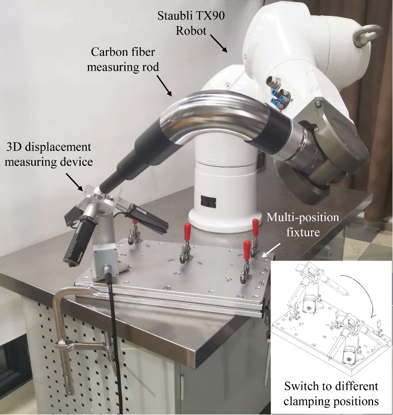
1. Introduction
Robot calibration involves measuring a robot’s end effector at different joint angles using high-precision measuring equipment to determine accurate kinematics parameters. Currently, calibration is typically performed after a robot’s manufacturing, known as in-house calibration. The advantages of in-house calibration include: First, the calibrated parameters can be embedded directly into the robot controller [
1]. Second, purchasing expensive measuring equipment such as laser trackers [
2], optical CMM [
3], and even CMM [
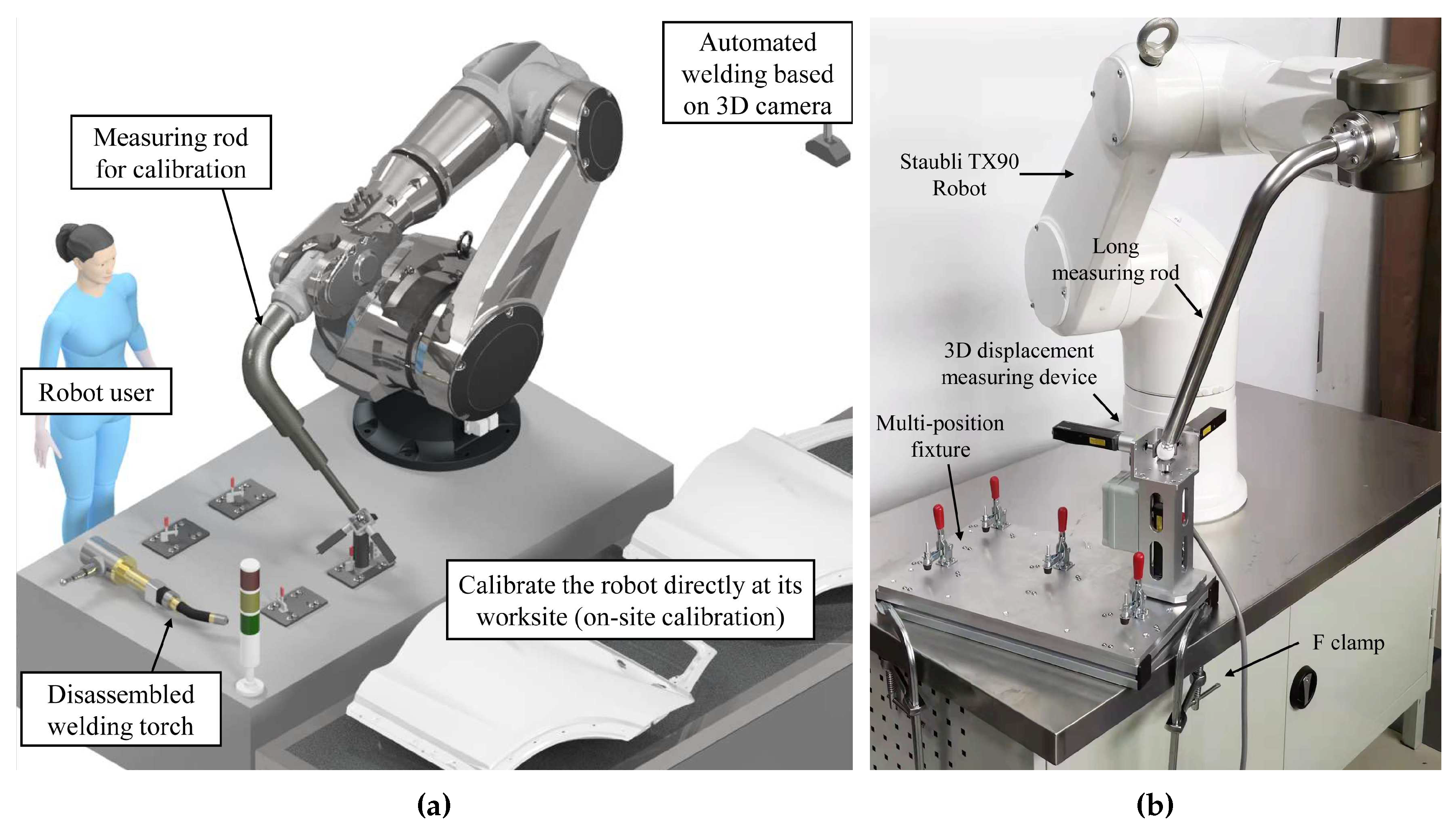
4] is cost-effective due to their high use frequency. However, the accuracy of robots degrades as they are continuously used, so it is necessary to monitor the robots’ accuracy online and conduct on-site recalibration (
Figure 1a) when the accuracy is severely degraded. On-site calibration is especially important for robots with off-line programming and visual navigation, as the absolute accuracy of a robot, rather than its higher repeatability, ensures that the motion instructions can be directly used for real tasks. Although some manufacturers provide on-site calibration services, most still have to rent expensive laser trackers from a local provider of metrology services [
1]. This has spurred many researchers to develop various portable and affordable measuring devices for on-site robot calibration.
When it comes to calibration devices, the requirements for on-site equipment differ from those for in-house calibration. Ideally, on-site equipment should have high calibration accuracy, low cost, good robustness, portability, good environmental adaptability (able to be used in small robot cells), versatility (suitable for different-sized robots), while also being able to monitor robot accuracy online. Note that on-site calibration equipment does not require full automation or extremely high time efficiency since calibration frequency is not high and manual interventions must be involved (to arrange the measuring devices). Additionally, the device must measure the robot in a large portion of its motion space to ensure high calibration accuracy. By keeping these requirements in mind, real industrial applications can choose the best on-site calibration device to fit their needs.
MultiCal [
6] (
Figure 1b) is such a measuring device designed for the on-site calibration of industrial robots. Its design features a long measuring rod with a spherical tip that is attached to the robot. The calibration procedure of MultiCal involves aligning the rod’s tip to multiple fixed points under different rod orientations, the relative positions of these points are accurately measured beforehand. However, for large robot calibration, the measuring rod of MultiCal have to be elongated and may enlarge gravity deformation of the rod, which increase measurement errors into the system. To address this issue, we propose two improvements in this paper. Firstly, we suggest a new design of the measuring rod that is lightweight yet has high rigidity. Secondly, a deformation compensation algorithm is proposed to reduce the error. The work is based on previously published paper on MultiCal [
6]. Details of the improvements are discussed in the following sections.
The remainder of this paper is organized as follows.
Section 2 reviews and analyses related works. In
Section 3, a new design scheme and calibration method of the MultiCal is discussed.
Section 4 analyzes the deformation of the measuring rod. Experimental setup and results are proposed in
Section 5. Comparisons of different measuring devices and methods are also discussed in the section. Finally, the paper is concluded in
Section 6.
2. Related works
Current calibration devices can be divided into two categories: open-loop and closed-loop, each utilizing different calibration methods. Open-loop devices require markers to be installed on the robot’s end effector, and measurements are performed using devices such as laser trackers [
2], optical CMMs [
3], CMMs [
4], binocular vision [
7], and wire draw encoders [
8]. This method allows for almost unlimited robot poses, and measurements can be automatically collected over a large workspace. Therefore, these devices (especially laser trackers) are commonly used for in-house calibration. However, open-loop devices may be obstructed in small robot cells and are often very expensive (> 50K USD).
Closed-loop devices rely on probes [
9], displacement sensors [
10], optical sensors [
11], precision balls [
12], and standard blocks [
13]. A typical closed-loop method is to restrict the robot’s tool center point (TCP) to a fixed point and then change the orientation of the end effector. These measuring devices inherently have the advantages of good environmental adaptability and low cost. However, their major limitation is that the robot must be restricted to a certain pose to collect the measurements, which lead to degraded calibration accuracy and collision risks.
To overcome the limitations of open-loop calibration devices and make them more suitable for on-site calibration, closed-loop devices based on multi-point constraints have been proposed. Two examples of such devices are TriCal [
14] and MultiCal [
6]. These devices use a similar measurement process, in which the robot automatically aligns its TCP with multiple fixed points, based on the feedback of three displacement sensors. By using multi-point constraints, these devices achieve a stronger constraint and a larger measurement space, resulting in good calibration accuracy and robustness.
Compared to TriCal, MultiCal uses a precision ball instead of a heavier 3D displacement measuring device at the end of its measuring rod. This design reduces the rod’s gravity deformation while allowing for a longer measuring rod, resulting in increased motion space and improved calibration accuracy for the robot. Although the measurement process of MultiCal is more complex than that of TriCal due to the need for manual switching of the measuring device to different clamping positions, it is less prone to collisions and more robust. This is because its displacement sensors have a larger measurement range of 30
, and the multi-position fixture has no vulnerable components that are critical to system accuracy, such as the extension stems. MultiCal is therefore well-suited for on-site calibration devices that are not frequently used and typically operated by non-professionals. However, our previous work [
6] showed that even though MultiCal has minimized the load on the measuring rod as much as possible, its lengthened stainless-steel measuring rod still suffered from gravity deformation, which could result in decreased calibration accuracy.
Deformation of structural components is a common problem in many measuring or machining devices, especially those involving slender structural components, which results in a decrease in measurement or machining accuracy. To address this issue, the conventional method is to estimate and compensate for deformation errors using elastic modeling [
15], finite element analysis (FEA) [
16], experimental measurement [
17], or neural network estimation [
18]. As the gravity deformation of the measuring rod is a relatively simple elastic deformation problem, this article adopts the first three methods based on considerations of robustness and accuracy.
3. Improvement of the calibration devices and methods
This section first describes the detailed design scheme of MultiCal. Then the robot kinematics model, non-kinematics parameters, calibration algorithm, and compensation algorithm for rod’s gravity deformation used during calibration are presented.
3.1. Design of MultiCal and measuring rod
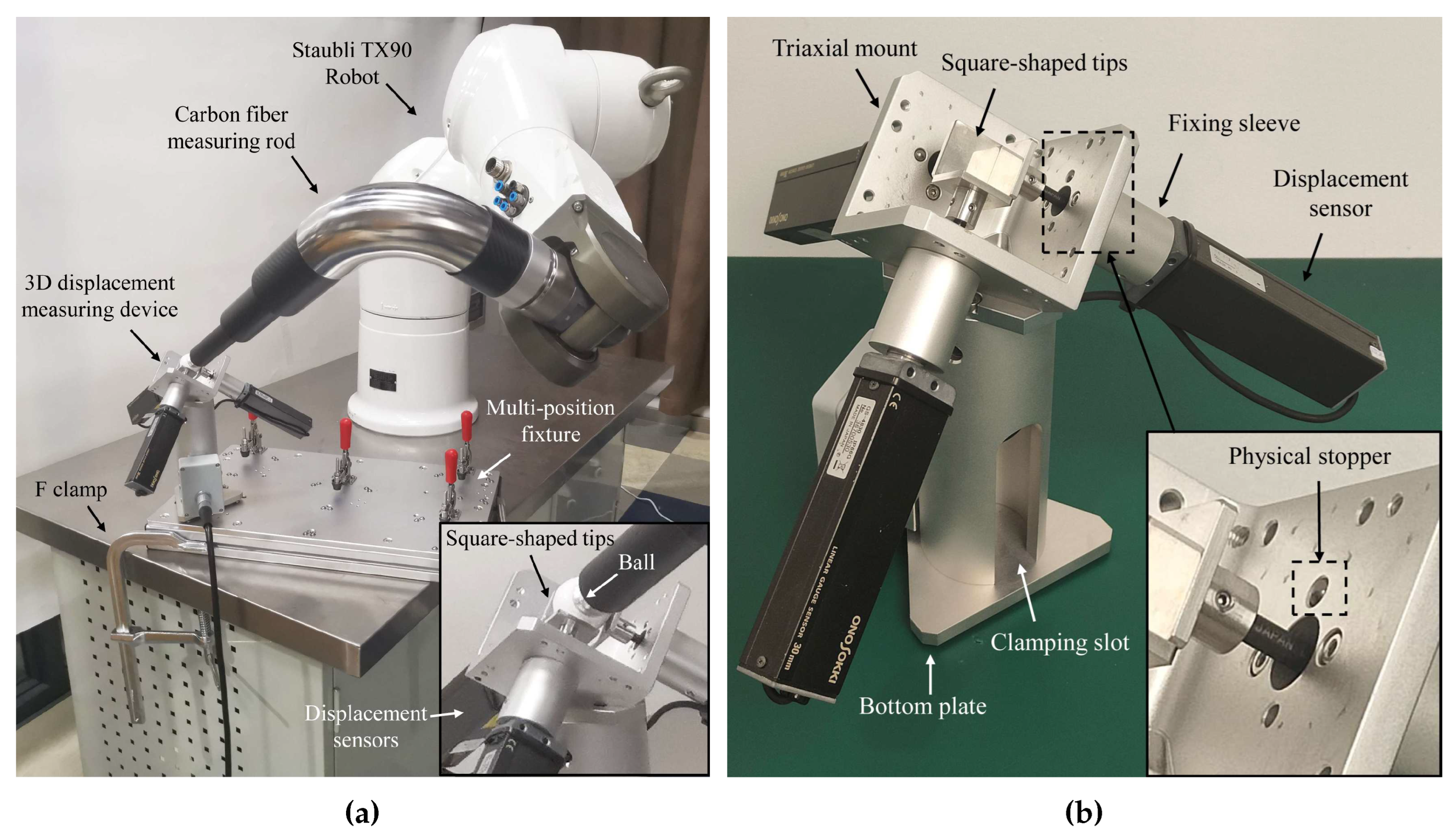
The improved design of MultiCal is illustrated in
Figure 2a. The device comprises three major components: (1) a long carbon fiber measuring rod with a spherical tip made up of a precision ceramic ball installed at the robot’s end, (2) a redesigned 3D displacement measuring device with a
level accuracy, and (3) a fixture providing multiple clamping positions that are fixed with respect to (w.r.t.) the robot’s base. MultiCal adopts the automatic alignment of the TCP (the spherical tip’s center) with a fixed point based on the feedback from three displacement sensors. Noted that the measuring rod does not need high dimensional accuracy but high rigidity and lightweight.
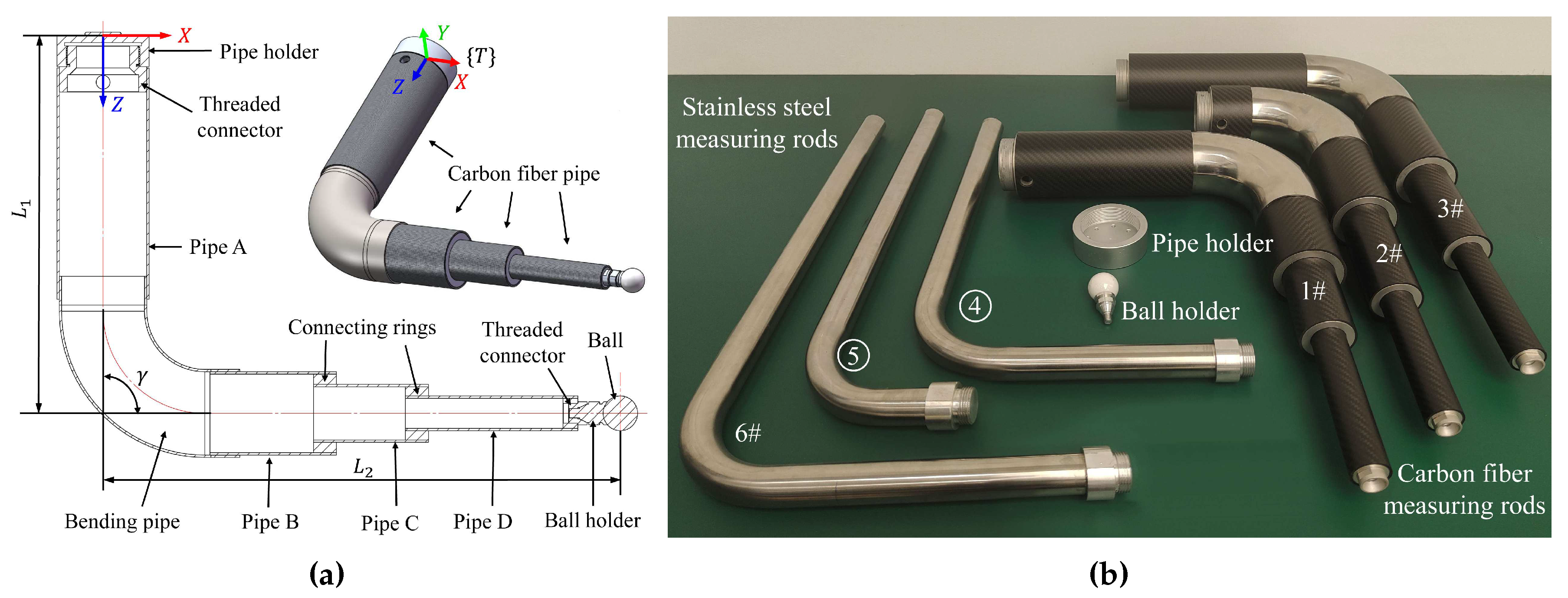
Measuring rod is improved by using new structure and carbon fiber pipes, as depicted in
Figure 3a. Two high-strength aluminum rings connect different carbon fiber pipes, and a stainless-steel bending pipe is used at the bend. All parts of the rod are bonded with high-strength epoxy resin adhesive. Pipe holder and ball holder are installed at the first and last ends of the measuring rod using threaded connectors, which are used for rapid installation and removal with the robot flange and precision ball. Three different configurations carbon fiber rod (
Figure 3b, see
Section 1 of supplementary materials for detail design parameters) is developed to replace previously-used stainless-steel measuring rods in [
6].
The measuring rod is mounted as an end-effector on the robot, and the position
of the precision ball’s center w.r.t. the tool frame
(tool parameters) can be calculated by Eq. (
1) as nominal values. As shown in
Figure 2b, the 3D displacement measuring device measures the displacement of the center of the measuring rod’s spherical tip. Three displacement sensors are installed orthogonally on an aluminum triaxial mount, ensuring that the sensors’ measuring axes are perpendicular to each other.
The measurement process involves making contact between the precision ball and the square-shaped tips of the sensors. The sensors are zeroed by pushing each square-shaped tip into contact with a physical stopper (a tungsten steel ball) set on the triaxial mount. In contrast to [
6], all three measuring axes of the sensors are inclined upwards at the same angle (approximately 54.7°) relative to the plumb axis. This design provides a larger measuring space in the vertical upward direction, enabling the robot to move more freely.
Using the feedback from the displacement sensors, the robot can adjust its TCP to a fixed point in
k different orientations and ensure that the measured values of all sensors are almost exactly half of their ranges. The corresponding
k sets of joint angles
and the small displacement deviation
are then recorded. This process is designed to automatically [
14] or semi-automatically [
6] achieve a point constraint with minimal contact force, resulting in minimal deformation, fast efficiency, and high measurement accuracy. The constrained point is marked as the virtual datum point.
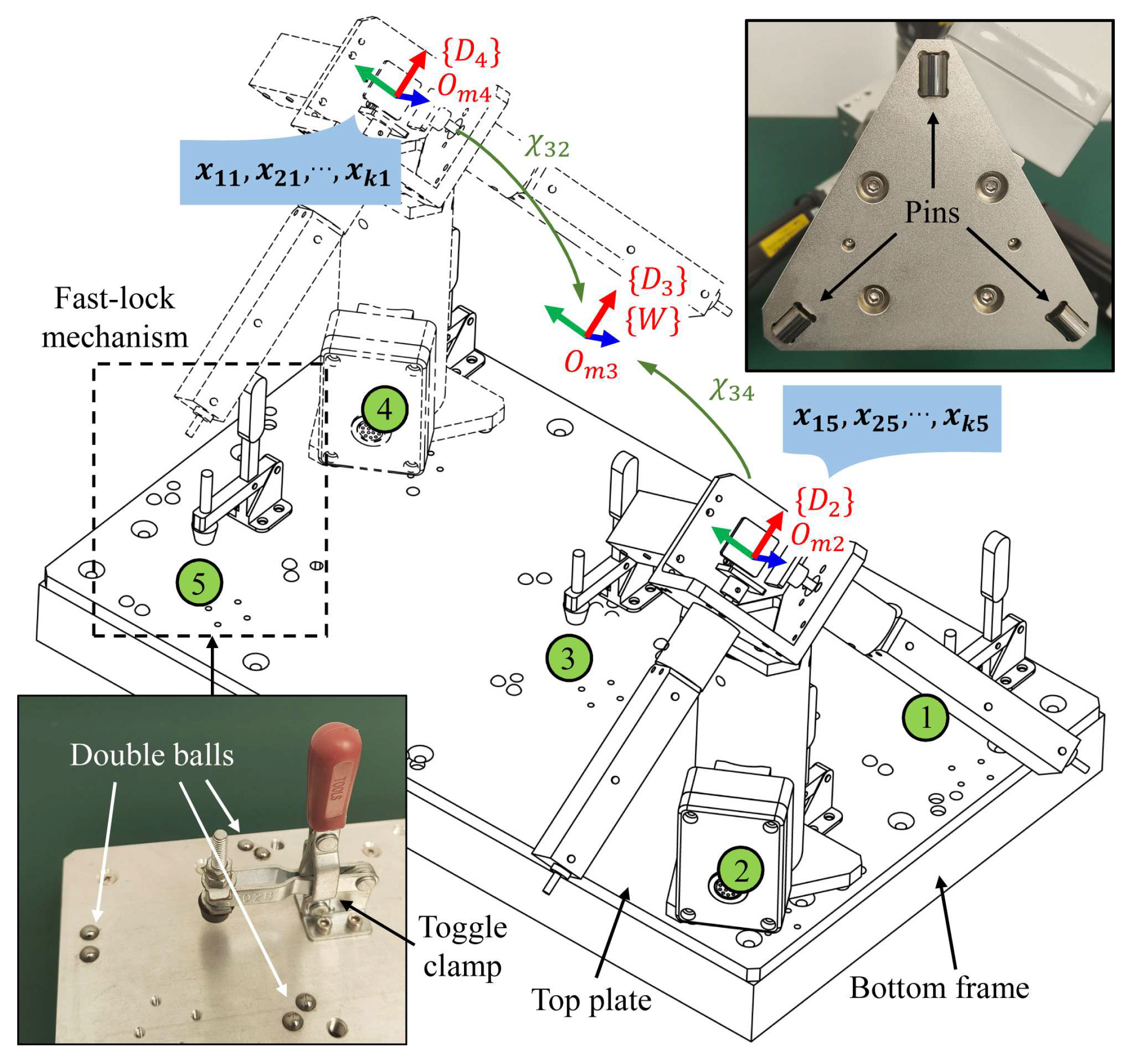
The MultiCal system also includes a fixture with multiple clamping positions fixed relative to the robot base, such as the multi-position fixture shown in
Figure 4. This fixture is designed to be compact and lightweight, making it easy to transport and embed in robot cells. Equipped with multiple fast-lock mechanisms, which comprises a toggle clamp and three sets of point positioning components made of tungsten steel. These components, consisting of a single pin and two balls spaced at a certain distance, ensure assembly accuracy.
The fast-lock mechanisms allow users quickly mount the 3D measuring device on different clamping positions (less than 15 second), repeat the above measurement process, and obtain the corresponding measurement data
and
(
;
) (assuming that five clamping positions are used). The displacement deviation
is regarded as the coordinate of the
i-th point measured on the
j-th clamping position w.r.t. the device frame
(
). A Hexagon measuring arm is used to measures the relative positions between different device frames (see
Section 2 of supplementary materials for specific method), which can convert the coordinate points in different frames to a single frame (
is chosen in this paper), marked as the world frame
.
Specifically, the relative poses between
and the other device frames are recorded as
(
), which are 6D pose vectors comprising
coordinates and Euler angles. The equation for the coordinate conversion is:
where
is the function transforming the 6D pose vector into a transformation matrix, and
is the measured coordinates of the measurement point w.r.t. the world frame
. The above process essentially achieves multi-point constraints, thereby providing stronger constraints and making the kinematics parameter identification more robust. For a large robot, another solution involves permanently fixing multiple single-position fixtures near the robot base (
Figure 1a) and then using an external measurement device (such as a measuring arm or laser tracker) to measure
(
) before the long-term use of these fixtures.
3.2. Calibration method
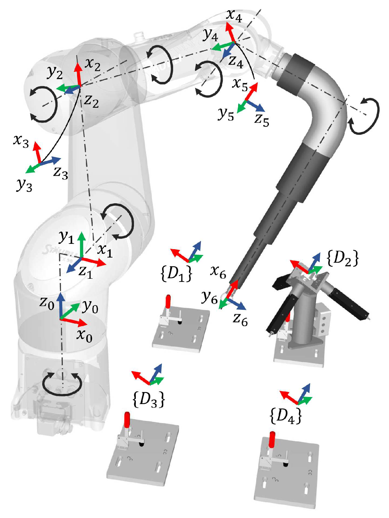
This section describes the robot kinematic model, the parameters that must be identified, and the calibration algorithm. In this paper, we use the Staubli TX90 robot (
Figure 5) as a representative, although MultiCal is suitable for calibrating most industrial robots and even machine tools using various measuring rods.
To begin the calibration process, we first establish a kinematic model and determine the parameters that require identification. In our previous work [
6], we compared different kinematic modeling methods, including Denavit-Hartenberg (DH), modified DH (MDH) [
19], product of exponential (POE) [
20], and finite and instantaneous screw (FIS) [
21]. After considering implementation and promotion difficulty, we ultimately selected the MDH method.
As shown in
Table 1, we define the center of the precision ball as the origin of the last frame (TCP), and add a rotation angle
around the
y-axis to the adjacent parallel joints (link 1-2) to eliminate the singularity. Additionally,
must be zero. Furthermore, both
and
are coupled with the 6D base parameter
from the robot base frame
to the world frame
and are thus not included in parameter identification. The compliance in the gearboxes of all joints, except the first, is modeled as a linear torsional spring [
14], as no torque is applied to the first joint axis when the robot is stationary. We combine these kinematic and non-kinematic parameters into the parameter vector
that we aim to identify.
where
,
,
,
, and
are the errors of the MDH parameters,
is the vector of robot base parameters,
is the vector of tool parameters,
is the vector of the compliance coefficient of the joint gearboxes, and
(
) is the torque applied on the five joints, which is calculated using the iterative Newton-Euler algorithm [
14]. Among them,
is a 6D vector, including
coordinates and Euler angles, as presented in Eq. (
4).
It is worth noting that the error associated with the tool parameters,
and
, and the tool angler error,
, are relatively larger due to the low dimensional tolerance of the measuring rods. The transformation matrix
between the tool frame
and the world frame
can be calculated based on the robot forward kinematics equation,
where
,
, and
are the transformation matrix between the robot base frame and the world frame, adjacent robot link frames, and the robot flange frame and the tool frame, respectively. Among them, the values of
and
are determined by the robot base parameters
and the tool parameters
, respectively. Based on Eq. (
5), the TCP’s nominal coordinates (the position vector of
) w.r.t. the world frame
can be obtained.
where
is the nominal coordinate of the
i-th point (
) measured on the
j-th clamping position (
), and
is the vector of torques applied on the robot joints when measuring this point. Then, a linear error model is established based on the difference between the measured coordinates
and the nominal coordinates
, and the error vector
can be solved by the least square method, namely.
Since the above linear error model still has errors,
can be optimized iteratively by using the Levenberg-Marquardt (LM) algorithm, which is commonly used in robot kinematics [
22] and has strong robustness. Essentially, the identification problem becomes an optimization problem.
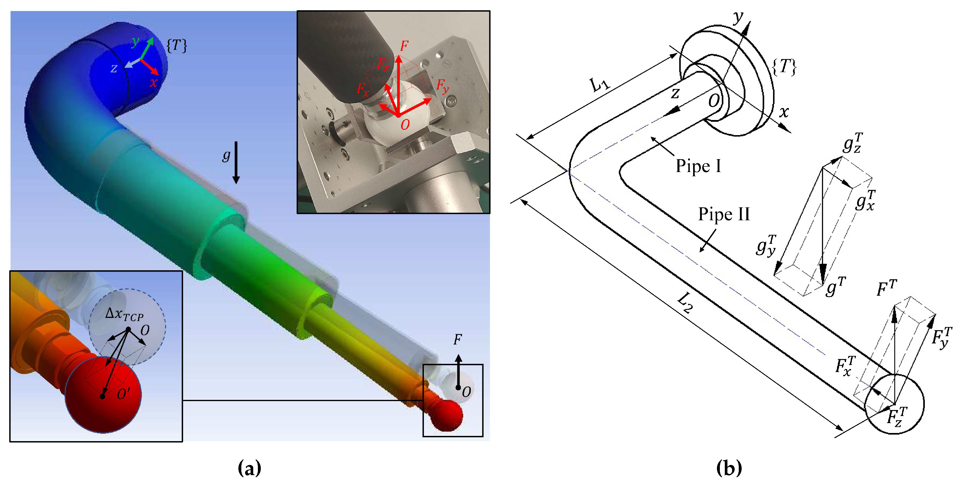
Figure 6a illustrates the TCP offset (
.) caused by rod gravity and the reaction force
from the measuring sensors. This reaction force
comprises the contact forces of the three displacement sensor tips (
), which are accurately measured using a force-measuring device. As the axes of the three sensors are parallel to the
axis of the device frame
(
), the contact force values of the three tips when the ball’s center coincides with the virtual datum point are directly used as the vector value of
w.r.t. the frame
. Since the TCP is aligned with the same point fixed w.r.t. the device each time, the vector value of
(determined by the compression of the springs) is considered constant in each measurement.
The TCP offset vector of the measuring rod when measuring the
i-th point on the
j-th clamping position is marked as
, which can be decomposed into the
direction of the tool frame
.
Then the measured coordinates of the TCP can be compensated to obtain the corrected coordinates
of this point.
where
is the rotation matrix between the world frame
and the tool frame
. We use
to replace
in Eq. (
9), and the calibration after compensation can be conducted.
4. Study on the the measuring rod’s deformation
In this section, we discuss the elastic deformation model of the measuring rod caused by gravity and contact force, which can degrade the measurement accuracy and require estimation and compensation. We then present how the compliance parameters associated with this model are obtained through a Finite Element Analysis (FEA) and a measurement experiment.
4.1. Elastic deformation model
The simplified measuring rod model and the external force decomposition is depicted in
Figure 6b. The measuring force vector
of the measuring device mounted on different clamping positions can be converted into the world frame
, namely:
where
is the measuring force vector (w.r.t. the world frame
) of the 3D measuring device mounted on the
j-th clamping position,
is the function transforming the Euler angles of the 6D pose vector
into a rotation matrix. After that,
is converted to the tool frame
, namely:
where
is the measuring force vector w.r.t. the tool frame
when measuring the
i-th point on the
j-th clamping position,
is the rotation matrix of the robot flange frame
and the tool frame
(determined by the tool parameters
),
is the rotation matrix between the robot base frame
and the flange frame
when measuring this point (determined by the robot kinematic model and joint angles
), and
is the rotation matrix between the robot base frame
and the world frame
(determined by the base parameters
). The robot first needs to be calibrated without considering the rod’s deformation to determine the “rough value” of the MDH parameters. This process is also called “rough calibration”. Experiments have proved that these MDH parameters are sufficiently accurate to estimate the measuring rod’s deformation.
The gravitational acceleration vector
can be also converted into the tool frame
, namely:
where
,
, and
are the gravitational acceleration vector w.r.t. the tool frame
, robot base frame
, and global frame when measuring the
i-th point on the
j-th clamping position, respectively. Then,
and
are decomposed into the
direction of the tool frame
(
Figure 6b). According to the principle of linear superposition in material mechanics, we analyze the deformation of the pipes I and pipes II caused by the
components of
and
, respectively, and then add them up. Then, the offset vector
of the ball’s center (TCP) caused by the measuring force of the 3D measuring device mounted on the
i-th clamping position can be calculated based on Eq (
15) (see
Section 3 of supplementary materials for the detailed derivation process).
where
E,
G,
and
are the elastic modulus, shear modulus, moment of inertia, and polar moment of inertia of the hollow pipes. Each element of the matrix in Eq. (
15) can be defined as a compliance coefficient
(
;
) of the measuring rod in the corresponding direction, namely:
where
is the compliance matrix for the measuring force, an inherent property of the measuring rod. Instead of stiffness, compliance (the reciprocal of stiffness) is used to make the formula more concise. Note that
and
will only cause TCP offset in the
X and
Z directions, while
will only cause the TCP offset in the
Y direction.
Similarly, the TCP offset vector
(w.r.t. the tool frame
) caused by gravity is calculated based on Eq (
17).
where
is the uniform load exerted by gravity acceleration on the hollow pipe, determined by gravity acceleration, the section shape of the hollow pipe, and the material density. We extract the gravity acceleration vector
in
, namely:
where
is the compliance coefficient matrix for gravity, another inherent property of the measuring rod. In summary, we only need to determine the compliance coefficients
and
(
;
) in
and
. Then the final overall TCP offset vector
can be estimated and compensated using Eq. (
19) and Eq. (
11).
4.2. Determination of rod compliance coefficients
To estimate the rod deformation error using the model derived above, we need to determine the compliance coefficients of the measuring rod in the
directions. To achieve this, we conducted both a finite element analysis (FEA,
Figure 6a) and a real measurement experiment to obtain these parameters. Firstly, we imported the 3D model of the measuring rod, built in SolidWorks, into ANSYS to perform a static deformation analysis. This allowed us to obtained the maximum directional deformation values of the spherical tip in the
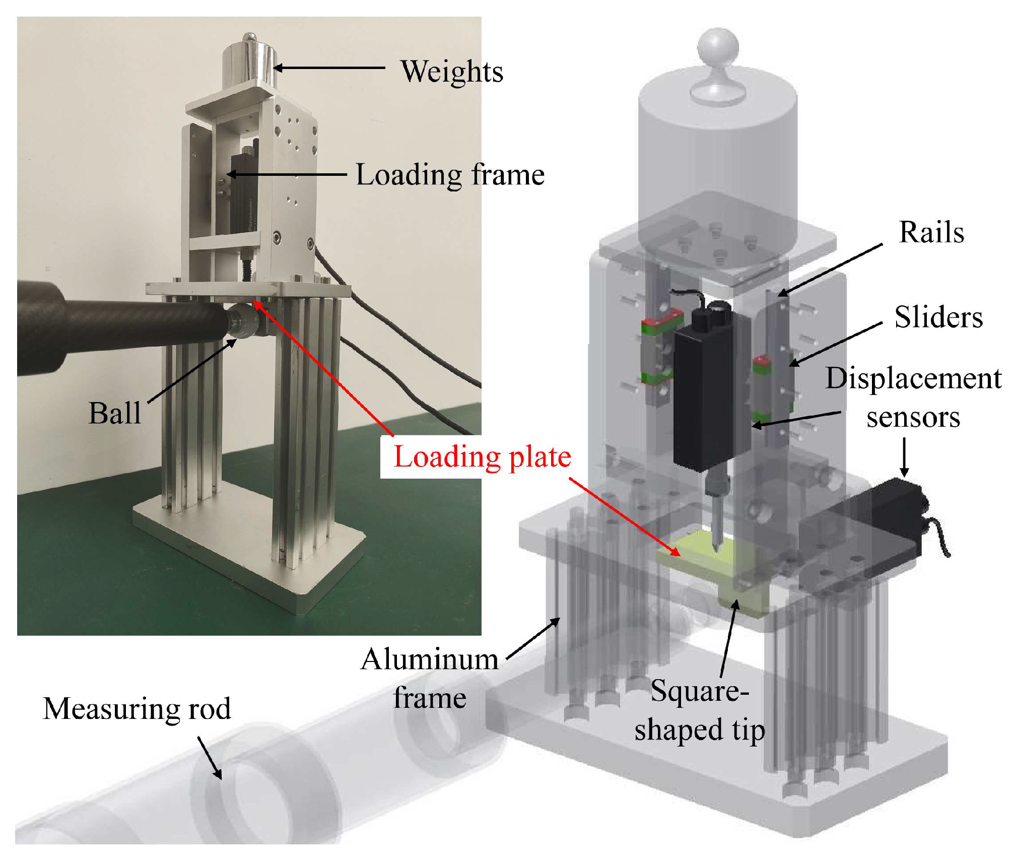
directions, which approximates the TCP offset values. These values were used to calculate the corresponding compliance coefficients. Secondly, a two-dimensional stiffness measuring device has been developed to determine the stiffness through measurements (
Figure 7, see
Section 4 of supplementary materials for detail design and measurement results). By putting different weights on the loading frame, we can apply different loads to the measuring rod and measure its vertical and horizontal TCP offset under the load. The TCP offset measurement method satisfies the Abbe measuring principle [
23] and eliminates errors caused by the rotation of the loading plate.
Moreover, a correction factor
r is defined to characterize the difference between the FEA simulated stiffness and the measured stiffness, namely:
where
is the slope of the fitting lines of the actual measured load-deformation result (
Figure 8), and
is the compliance coefficient obtained by the FEA result. The correction factor
of a measuring rod in different directions calculated by Eq. (
20) is usually different. In the direction with a small deformation (high stiffness), the correction factor
is more susceptible to the measurement error. Therefore, we assume the correction factor
of all directions is a fixed value since the measuring rod has a certain symmetry. The two directions with the largest deformation are selected (
and
) to calculate the overall correction factor
, namely:
Using normal instruments, it is difficult to measure the deformation of the measuring rod caused by the gravity. Therefore, we first obtain the compliance coefficients
(
;
) in the simulated environment using the FEA method, and then calculate the approximated actual compliance coefficients
by multiplying
by the overall correction factor
, namely.
Finally, all the compliance coefficients used for the deformation compensations are obtained. The unit used for
is the TCP offset value (unit:
corresponding to one gravitational acceleration
g. The compliance index
is defined and used to evaluate the overall compliance of a measuring rod.
where
F is the magnitude of the measured force.
5. Experiments and Results
In this section, calibration experiments were performed on a Staubli TX90 robot using MultiCal, and the results were compared to those obtained using two other devices: a 6D binocular vision measuring system (NDI Polaris Vega, with an accuracy of ) and a measuring arm with a laser scanner (Hexagon AS1, with an overall accuracy of 43 ).
5.1. Measurement of Rod Stiffness
Rod stiffness is determined by both FEA and actual measurement using the device depicted in
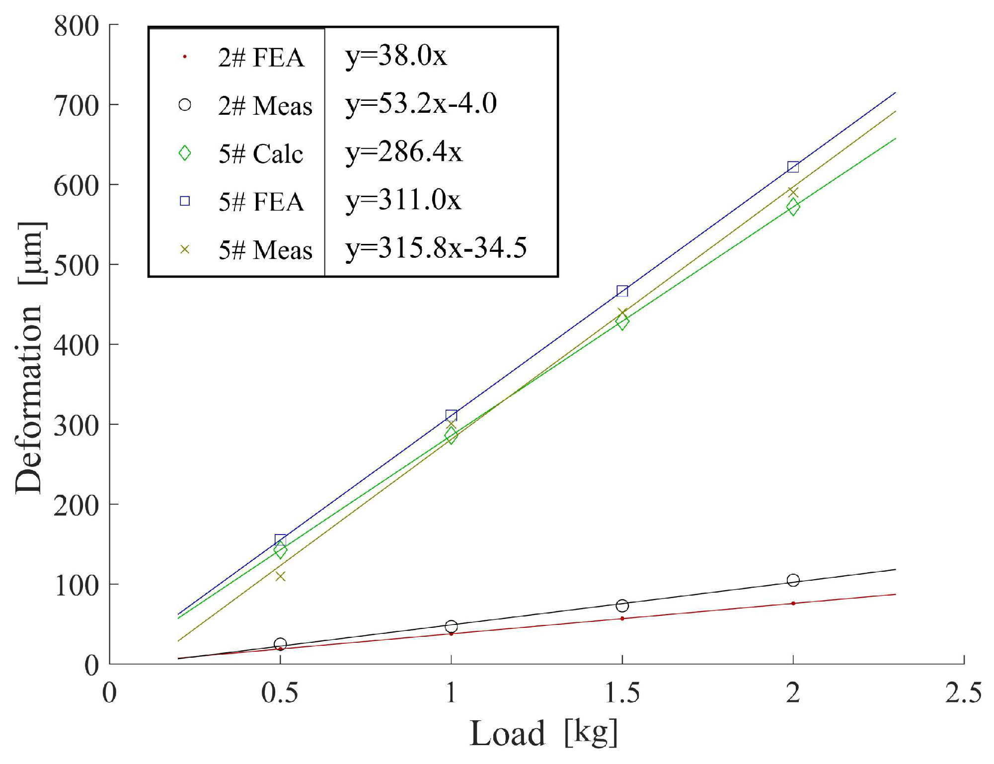
Figure 7. Gravitational loads of 0.5 kg, 1 kg, 1.5 kg, and 2 kg are applied and the resulting TCP offset measurement is repeated five times for each load. The average TCP offset is plotted in
Figure 8. We compare the
Y-directional compliance coefficients
of the 2# (carbon fiber) and 5# (stainless-steel) measuring rods as an example. Furthermore, the theoretical TCP offset (denoted as “5# Calc”) of the 5# measuring rod is also calculated based on Eq.(
15), because the structures of the stainless-steel measuring rods are similar to that of the theoretical model.
As depicted in
Figure 8, the carbon fiber measuring rod’s simulated and measured stiffness values are 8.1 and 5.9 times the stainless-steel measuring rod, respectively. The results prove the advantages of using carbon fiber measuring rods in reducing deformation and improving measuring accuracy. The theoretical calculation and FEA results are ideal elastic coefficient equations (
,
c is the compliance coefficient), and their fitting lines pass through the origin since they are all calculated in an ideal virtual environment. However, both fitting lines of the real measurement results of the 2# and 5# measuring rods intersect the
x-axis when the load is 0.09 kg to 0.11 kg (about 1 N). This is probably because of the friction in the rails and sliders in the device depicted in
Figure 7, making all the actual loads subtract this frictional force, reducing the overall deformation.
It should be noted that the linear condition of the carbon fiber measuring rod is only met under small loads (less than 15 N). As the load increases, nonlinear deformations, such as creep, become more pronounced. Therefore, it is important to avoid excessive loads on the rod, even when using carbon fiber rods in other closed-loop devices discussed in
Section 1. For instance, using a carbon fiber long mounting bracket in TriCal [
14] may not be as advantageous as MultiCal since the measuring device is considerably heavier than a precision ball.
5.2. Experiments of Calibration
MultiCal is actually a flexible design scheme that allows users to choose appropriate sensors and design parameters based on the specific needs of the robot being calibrated. In this study, a ceramic ball with a diameter of and a roundness error of 2 was used for the measuring rod. The displacement sensors employed were the ONOSOKKI GS-4830, with a measuring range of 30, a resolution of 1 , and an accuracy of 3 . Since the first axis of the robot is vertically installed on the workbench, the gravitational acceleration vector is equal to (unit: . The total contact force vector of the three displacement sensors was measured as (unit: using a high-precision force sensor.
The experiment employed a single multi-position fixture with external dimensions of 500 x 300 x 151
and a weight of 7.1 kg. This was found to be more accurate than using multiple single-position fixtures fixed on the robot workbench, possibly due to insufficient rigidity of the workbench causing slight deformation during measurement and introducing errors. The overall cost of MultiCal was less than 5K USD, and its measurement accuracy evaluation has been described in previous work [
6].
Thirty measurement configurations were selected for each measuring device based on the consideration of calibration accuracy and time efficiency [
6]. The configurations were optimized using the observation index (OI) [
24] study in RoboDK and MATLAB, and the maximum OI value for each rod was recorded as its theoretical calibration performance. Compliance index
and correction factor
for each measuring rod were determined through the stiffness measurement described above, and the values are shown in
Table 2. The same 30 configurations were used for the carbon fiber and stainless-steel measuring rods with the same structural dimensions (
and
). Additionally, the correction factor
showed that the 3# measuring rod had the greatest difference between the real and simulated stiffness, potentially due to creep deformation of the bonding parts of the rod.
During the calibration process with MultiCal, different measuring rods were installed at the end of the robot to conduct the measurements. The “rough calibration” was performed based on Eq. (
9), and then calibration with compensation algorithm and different sets of compliance coefficients was carried out based on Eq. (
19) and Eq. (
11). The kinematic parameters and joint stiffness parameters were then obtained by each measuring rod and method.
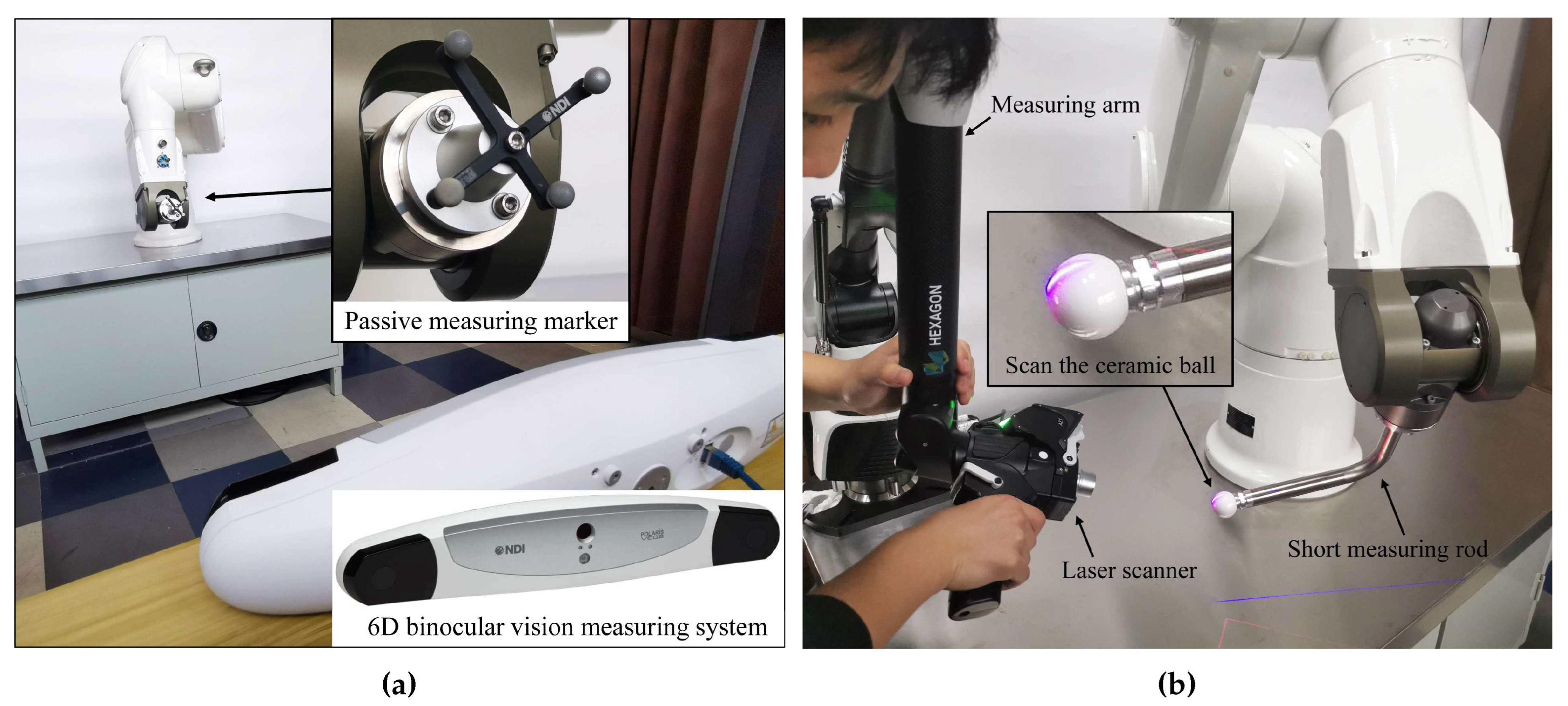
Afterward, the MultiCal system was removed, and a 6D binocular vision measuring system (
Figure 9) and a measuring arm with a laser scanner were used to conduct traditional calibration procedures, applying the method described in [
6]. A short measuring rod was installed at the robot’s end during the laser scanner trial to reduce deformation error, and the surface of the rod’s precision ball was scanned. The spherical center’s position was obtained through a spherical fitting in PolyWorks. The laser scanner and scanning method were also used for validation, with one hundred sets of robot configurations selected in a large portion of the robot’s workspace.
During the validation, the calibrated kinematic and non-kinematic parameters were imported into Eq. (
9), and only the tool and base parameters were optimized. The final absolute positioning error was then calculated. The nominal kinematic parameters and the nominal joint compliance coefficients (which are all zero) were imported into the process, and the average and maximum absolute positioning errors before calibration were calculated as 2.384
and 6.571
, respectively.
5.3. Result and Discussion
After conducting the calibration experiment, the results were obtained (
Table 3). The measuring arm with a laser scanner achieved the highest calibration accuracy, while the MultiCal system with various measuring rods and deformation compensation methods also demonstrated good calibration performance, improving the robot’s average and maximum positioning accuracy by 74% to 89% and 69% to 88%, respectively. However, the binocular vision system exhibited the poorest calibration accuracy, likely due to its lower measurement accuracy. Notably, almost all the improvement methods, including the use of carbon fiber measuring rods and deformation compensation methods, improved the MultiCal system’s calibration accuracy compared to the previous work presented in [
6]. Specifically, the MultiCal system with the 1# measuring rod and Meas compensation method achieved the highest calibration accuracy, with an average and maximum positioning accuracy of 0.274
and 0.838
, respectively, similar to that of the laser scanner.
Among the carbon fiber measuring rods, the 1# rod demonstrated the highest calibration accuracy, achieving 3% to 6% and 24% to 27% higher accuracy compared to the 2# and 3# rods, respectively, under the same deformation compensation method. This corresponds to the compliance of the 1# rod being only 83.2% and 22.1% of that of the 2# and 3# rods, respectively. Similarly, for the stainless-steel measuring rods, the 5# rod achieved the highest calibration accuracy, 16% to 18% and 26% to 35% higher accuracy than the 4# and 6# rods, respectively, with its compliance being only 80.8% and 31.7% of that of the 4# and 6# rods, respectively.
Regarding the three compensation methods evaluated, Meas and FEA increased the calibration performance by 6% to 16% compared to the non-compensation method, while Calc showed the poorest performance, yielding a positive effect only when using a long rod. Otherwise, Calc could even reduce the calibration accuracy due to modeling errors.
Surprisingly, the calibration results in this study were more strongly correlated with the stiffness of the measuring rod than the OI value. This could be because the OI value was already relatively high, and the identification error resulting from the singularity of the Jacobi matrix had a smaller effect than the rod deformation error. For example, the “375-600” rods, which had 7% to 13% higher OI values and 2.5 to 4.5 times higher compliance than the other rods, showed 10% to 35% lower calibration accuracy than the other rods.
Overall, using carbon fiber measuring rods with high stiffness (5 to 10 times that of stainless-steel rods of the same size) improved the calibration accuracy by 20% to 39%. In contrast, the deformation compensation methods had a more limited effect, increasing the calibration accuracy by only 6% to 16%. Notably, the compensation methods could only increase the calibration results of the 1# and 2# carbon fiber measuring rods with high stiffness by 6% to 10%. This could be due to the fact that high-rigidity measuring rods reduce the deformation error at the source and that even if the rod deforms, the main part of the TCP offset is downward (due to gravity), so its effect on the calibration accuracy can be largely reduced by optimizing the base parameters
in Eq. (
9). However, using compensation methods could be essential when calibrating large robots with long or less rigid rods.
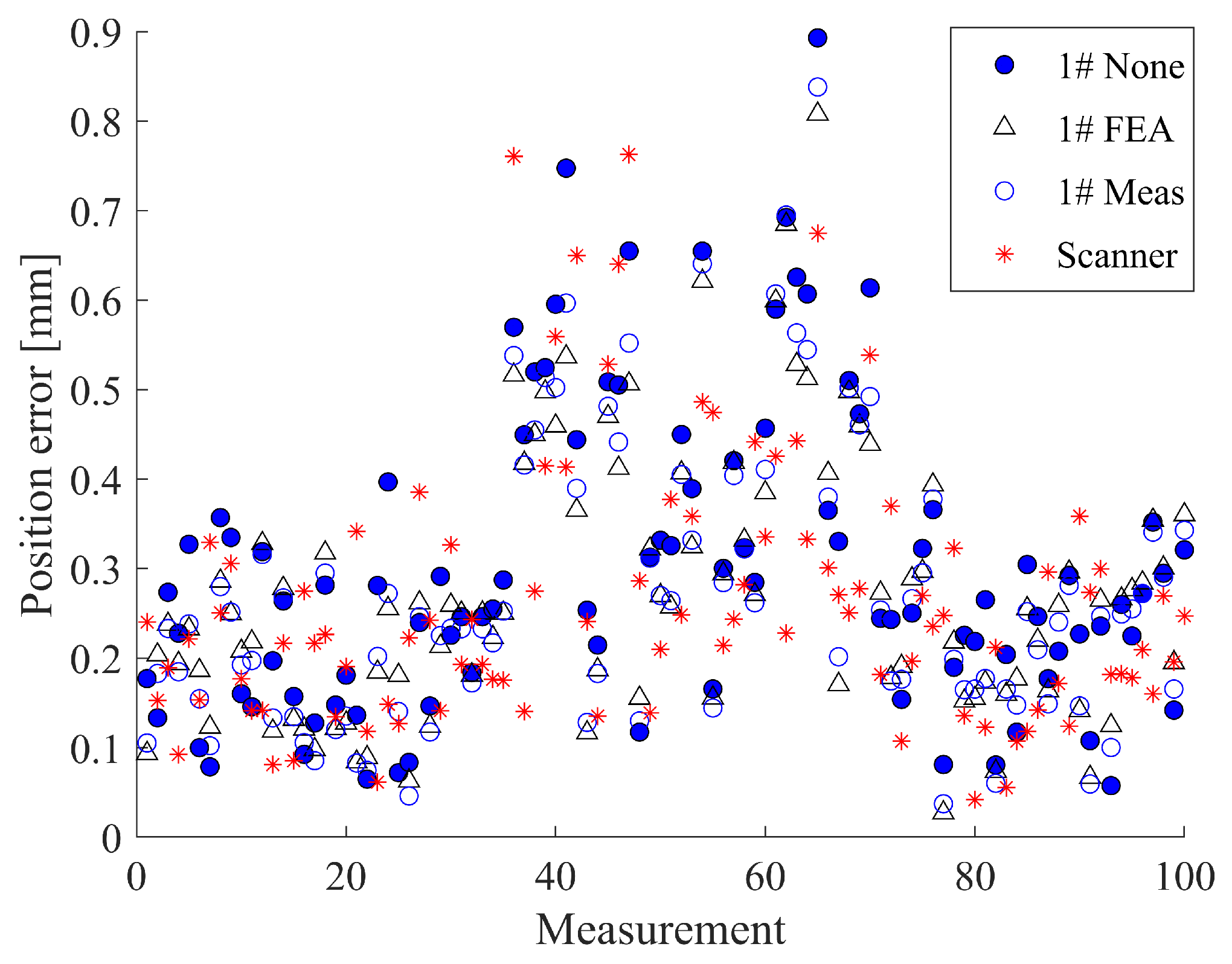
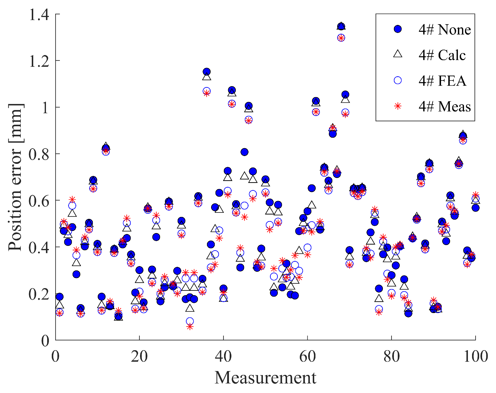
To facilitate a better comparison of the different compensation methods, we analyzed the positioning error distribution obtained by 1# and 4# using different methods (
Figure 10 and
Figure 11). The results indicate that the error distributions obtained by different methods are highly similar since these compensation methods only adjust the measurement coordinates slightly without significantly affecting the overall measurements. Moreover, the primary effect of deformation compensation is to reduce the error of large error points and make the error distribution more uniform. In the case of stainless-steel measuring rods, the results of Meas are comparable to those of FEA since their actual stiffness is close to the simulated stiffness (the rod correction factors
are close to one). For carbon fiber measuring rods with a correction factor
exceeding 1.2, in most cases, Meas is slightly better than FEA.
6. Conclusion
This paper presents the improved design of an in-contact and on-site calibration device, called MultiCal, which includes a well-designed long carbon fiber measuring rod and a rod deformation compensation algorithm. The redesigned MultiCal offers higher calibration accuracy, low cost (less than 5K USD), portability, and good robustness. The methods proposed in this paper can be applied to most traditional in-contact calibration devices to overcome their similar drawbacks, particularly when calibrating large robots. The results show that MultiCal achieves a calibration accuracy similar to that of a measuring arm with a laser scanner, with an average and maximum positioning error of 0.274 and 0.838 , respectively.
This paper also compares the newly-designed carbon fiber measuring rod with the previously-used stainless-steel measuring rod and different deformation compensation methods. The results indicate that the calibration accuracy can be improved by 20% to 39% when using carbon fiber measuring rods and by 6% to 16% when applying the deformation compensation algorithm. The best compensation method involves using the compliance coefficients of the measuring rods obtained from actual measurements and modified finite element analysis (FEA) results.
In the future, further research will explore the effectiveness of MultiCal in more scenarios, including the calibration of larger robots or the repeatability and accuracy monitoring of multiple robots. Additionally, the optimal location and number of clamping positions for 3D measuring devices require further study.
Author Contributions
Ziwei WAN and Chunlin ZHOU designed the research. Ziwei WAN, Zhaohui LIN, Huapeng Yan, Weixi Tang, and Zhen Wang processed the data and drafted the paper. Jun WU helped organize the paper. Ziwei WAN and Chunlin ZHOU revised and finalized the paper.
Funding
This research was funded by the Key R&D Program of Zhejiang Province (2022C04030), National Key R&D Program of China (2020YFB1313300) and the National Natural Science Foundation of China (61836015).
Conflicts of Interest
The authors declare no conflict of interest.
References
- Icli, C.; Stepanenko, O.; Bonev, I. New Method and Portable Measurement Device for the Calibration of Industrial Robots. Sensors 2020, 20, 5919. [Google Scholar] [CrossRef] [PubMed]
- Sun, T.; Zhai, Y.; Song, Y.; Zhang, J. Kinematic calibration of a 3-DoF rotational parallel manipulator using laser tracker. Robotics and Computer-Integrated Manufacturing 2016, 41, 78–91. [Google Scholar] [CrossRef]
- Nubiola, A.; Slamani, M.; Joubair, A.; Bonev, I.A. Comparison of two calibration methods for a small industrial robot based on an optical CMM and a laser tracker. Robotica 2013, 32, 447–466. [Google Scholar] [CrossRef]
- Cong, D.; Yu, D.; Han, J. Kinematic Calibration of Parallel Robots Using CMM. 2006 6th World Congress on Intelligent Control and Automation; IEEE: Dalian, China, 2006; Vol. 2, pp. 8514–8518. [Google Scholar] [CrossRef]
- Qiao, G.; Weiss, B.A. Accuracy Degradation Analysis for Industrial Robot Systems. Volume 3: Manufacturing Equipment and Systems; American Society of Mechanical Engineers: Los Angeles, CA, USA, 2017; Vol. 3, p. V003T04A006. [Google Scholar] [CrossRef]
- Wan, Z.; Zhou, C.; Zhang, H.; Wu, J. Development of an onsite calibration device for robot manipulators. Frontiers of Information Technology & Electronic Engineering 2023, 24, 217–230. [Google Scholar] [CrossRef]
- Chen, M.; Hong, X.; Wei, L.; Liu, Y.; Xu, C. Robotic arm calibration and teaching method based on binocular vision. 2020 39th Chinese Control Conference (CCC); IEEE: Shenyang, China, 2020; pp. 5963–5969. [Google Scholar] [CrossRef]
- Legnani, G.; Tiboni, M. Optimal design and application of a low-cost wire-sensor system for the kinematic calibration of industrial manipulators. Mechanism and Machine Theory 2014, 73, 25–48. [Google Scholar] [CrossRef]
- Zhong, X.L.; Lewis, J.M.; L. N.-Nagy, F. Autonomous robot calibration using a trigger probe. Robotics and Autonomous Systems 1996, 18, 395–410. [Google Scholar] [CrossRef]
- Gaudreault, M.; Joubair, A.; Bonev, I.A. Local and closed-loop calibration of an industrial serial robot using a new low-cost 3D measuring device. 2016 IEEE International Conference on Robotics and Automation (ICRA); IEEE: Stockholm, Sweden, 2016; pp. 4312–4319. [Google Scholar] [CrossRef]
- Enebuse, I.; Foo, M.; Ibrahim, B.S.K.K.; Ahmed, H.; Supmak, F.; Eyobu, O.S. A Comparative Review of Hand-Eye Calibration Techniques for Vision Guided Robots. IEEE Access 2021, 9, 113143–113155. [Google Scholar] [CrossRef]
- Joubair, A.; Bonev, I.A. Kinematic calibration of a six-axis serial robot using distance and sphere constraints. The International Journal of Advanced Manufacturing Technology 2014, 77, 515–523. [Google Scholar] [CrossRef]
- Ikits, M.; Hollerbach, J.M. Kinematic calibration using a plane constraint. Proceedings of International Conference on Robotics and Automation; IEEE: Albuquerque, NM, USA, 1997; Vol. 4, pp. 3191–3196. [Google Scholar] [CrossRef]
- Gaudreault, M.; Joubair, A.; Bonev, I. Self-Calibration of an Industrial Robot Using a Novel Affordable 3D Measuring Device. Sensors 2018, 18, 3380. [Google Scholar] [CrossRef] [PubMed]
- Wu, J.; Cheng, L.; Bi, Y.; Li, J.; Ke, Y. Kinematic modeling and parameter identification for a heavy gantry-type automated fiber placement machine considering gravity deformation. Proceedings of the Institution of Mechanical Engineers, Part C: Journal of Mechanical Engineering Science 2020, 235, 1418–1431. [Google Scholar] [CrossRef]
- Fu, H.Y.; Wang, H.; Han, Z.Y. Modeling and Analysis of Key Geometric Error for Gravity Deformation of Heavy-Duty CNC Machine Tool. Applied Mechanics and Materials 2014, 552, 90–95. [Google Scholar] [CrossRef]
- Vrhovec, M.; Kovac, I.; Munih, M. Measurement and compensation of deformations in coordinate measurement arm. 2010 International Symposium on Optomechatronic Technologies; IEEE: Toronto, ON, Canada, 2010; pp. 1–6. [Google Scholar] [CrossRef]
- Gao, G.; Zhang, H.; San, H.; Wu, X.; Wang, W. Modeling and Error Compensation of Robotic Articulated Arm Coordinate Measuring Machines Using BP Neural Network. Complexity 2017, 2017, 1–8. [Google Scholar] [CrossRef]
- Hayati, S.; Mirmirani, M. Improving the absolute positioning accuracy of robot manipulators. Journal of Robotic Systems 1985, 2, 397–413. [Google Scholar] [CrossRef]
- Park, F.C.; Okamura, K. Kinematic Calibration and the Product of Exponentials Formula. In Advances in Robot Kinematics and Computational Geometry; Springer Netherlands, 1994; pp. 119–128. [CrossRef]
- Sun, T.; Liu, C.; Lian, B.; Wang, P.; Song, Y. Calibration for Precision Kinematic Control of an Articulated Serial Robot. IEEE Transactions on Industrial Electronics 2021, 68, 6000–6009. [Google Scholar] [CrossRef]
- Luo, G.; Zou, L.; Wang, Z.; Lv, C.; Ou, J.; Huang, Y. A novel kinematic parameters calibration method for industrial robot based on Levenberg-Marquardt and Differential Evolution hybrid algorithm. Robotics and Computer-Integrated Manufacturing 2021, 71, 102165. [Google Scholar] [CrossRef]
- Fan, K.C.; Liu, C.L.; Wu, P.T.; Chen, Y.C.; Wang, W.L. The Structure Design of a Micro-precision CMM with Abbé Principle. In Proceedings of the 35th International MATADOR Conference; Springer London; 2007; pp. 297–300. [Google Scholar] [CrossRef]
- Joubair, A.; Nubiola, A.; Bonev, I. Calibration Efficiency Analysis Based on Five Observability Indices and Two Calibration Models for a Six-Axis Industrial Robot. SAE International Journal of Aerospace 2013, 6, 161–168. [Google Scholar] [CrossRef]
|
Disclaimer/Publisher’s Note: The statements, opinions and data contained in all publications are solely those of the individual author(s) and contributor(s) and not of MDPI and/or the editor(s). MDPI and/or the editor(s) disclaim responsibility for any injury to people or property resulting from any ideas, methods, instructions or products referred to in the content. |
© 2023 by the authors. Licensee MDPI, Basel, Switzerland. This article is an open access article distributed under the terms and conditions of the Creative Commons Attribution (CC BY) license (http://creativecommons.org/licenses/by/4.0/).
