1. Introduction
Nowadays, several manufacturing processes such as laser welding, additive manufacturing and casting are based on the total fusion of material, followed by rapid solidification [
1,
2,
3]. The material's structure in the final phase and its mechanical and electrical properties strongly depend on the solidification phase [
4,
5,
6]. This phenomenon becomes particularly apparent when the material comprises a metal alloy or a combination of two different materials. For instance, when specific connectors are joined to battery cells through lap joining, typically using laser welding, during the production of battery packs for electric vehicles. [
7,
8]. The assembly of battery packs powering EVs is a hot topic that attracts the attention of researchers and industrials. The integrity of the assembly plays a crucial role in the reliability of the battery pack as well as in its electrical performance [
9,
10].
The variation in melting temperatures among different metals results in the simultaneous presence of liquid and solid phases. This means that particles with similar characteristics tend to cluster together within the molten pool [
11,
12], which ideally should be dispersed homogeneously throughout the liquid phase during solidification [
13]. The occurrence of voids and gas, along with the variability in grain size, are commonly observed phenomena. These phenomena can lead to a degradation of the final material's properties [
14,
15], leading to problems such as hot cracking [
16]. Therefore, the battery connection might be fragile and exhibit significant electrical resistance, resulting in energy wastage and increased battery pack temperatures. [
17,
18].
Ultrasonic-assisted laser welding is a welding technique where ultrasonic vibrations and laser energy are applied simultaneously. The ultrasonic vibrations, usually ranging from 20 to 40 kHz, generate controlled mechanical oscillations at the welding interface. These vibrations yield positive outcomes such as better material flow, improved diffusion, and increased malleability [
19,
20,
21]. Conversely, the laser energy supplies localized heat to melt and fuse the materials together [
22,
23,
24]. By incorporating ultrasonic vibrations alongside the welding, the integration facilitates superior blending of materials, resulting in robust and dependable welds. This combination effectively addresses concerns such as porosity, insufficient fusion, and cracking, thereby elevating the overall quality and integrity of the welds [
25,
26,
27].
Typically, vibration-assisted welding utilizes High Power Ultrasonic Transducers (HPUTs) to induce out-of-plane displacement using contact excitation. The main focus of this research revolves around utilising contactless vibration to enhance the quality of spot welding. For this purpose, a detailed characterisation of an ultrasound transducer equipped with a focused horn, capable of integration with a laser welding system, was conducted. The characterisation involved determining the optimal angle and distance for generating maximum vibration. The results obtained from both non-ultrasound welding and contactless vibration-assisted welding were analysed. The data indicated a decrease in welding impedance value of the weld when contactless vibration was employed. Furthermore, this study examines the impact of employing contact vibration, specifically generating mainly shear or compressional waves, to evaluate its effects on the welding impedance value. To connect the battery cell through ultrasonic-assisted laser welding, most clients prefer to have low-intensity vibration on their battery cells to prevent the generation of shock waves which can damage the key parts in a battery. Therefore, this study compares the outcomes of contact vibration with contactless vibration-assisted welding and non-ultrasonic welding to provide a comprehensive analysis of their respective results.
2. Contactless vibration of the plate
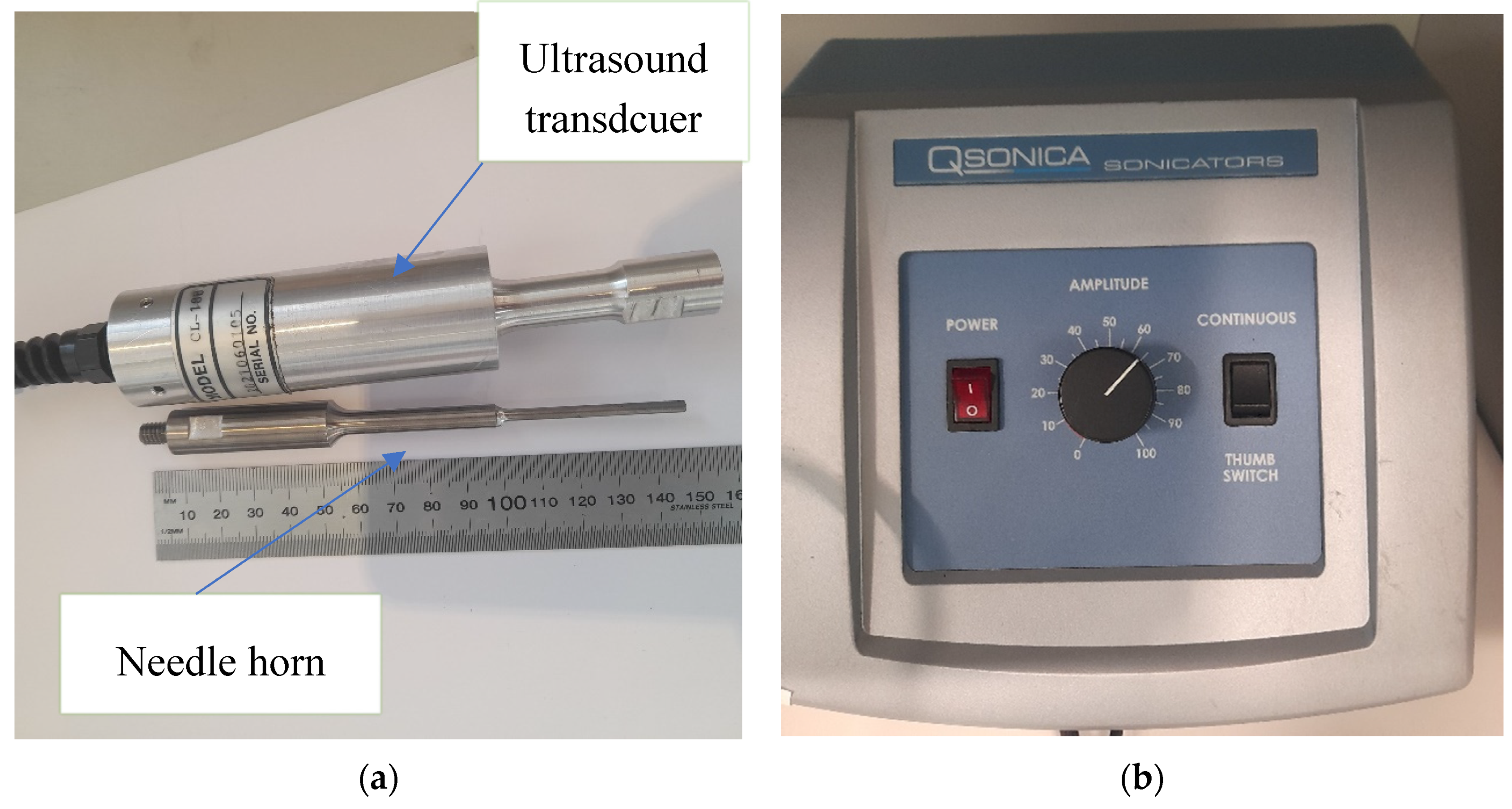
This section focuses on the characterization of an industrial High Power Ultrasonic Transducer (HPUT) named Q55, aiming to determine the optimal output of contactless vibration from this device. The transducer is comprised of a long-focused horn, which is conveniently connected to the transducer itself through a user-friendly amplifier (see
Figure 1). The Q55 is an ultrasonic processor that offers a compact and affordable solution, taking up minimal bench space. It is particularly suitable for standard cell disruption and various small volume applications. The transducer associated with this model has a power rating of 55 watts, operates at a frequency of 20kHz, and has dimensions of 203mm x 190mm x 146mm (width x length x height). The accompanying horn for this transducer features a tip diameter of 2mm and a maximum displacement of 200 μm [
28].
To characterize the transducer, the vibration it generates is applied to an L-shaped plate at various angles ranging from 5 degrees to 80 degrees. This range of angles allows for a comprehensive assessment of the transducer's performance and its impact on the plate's response. The plate was made of aluminum alloy 1050 and has a thickness of 2 mm. To measure the response of the plate, a 3D laser vibrometer is employed, as depicted in
Figure 2. The plate's response is collected in three perpendicular directions: 1) the out-of-plane displacement along the z-direction, 2) the in-plane vibration along the x-direction, and 3) the in-plane vibration along the y-direction. While the L plate remains fixed and firmly attached to its base, the position of the transducer can be adjusted accordingly.
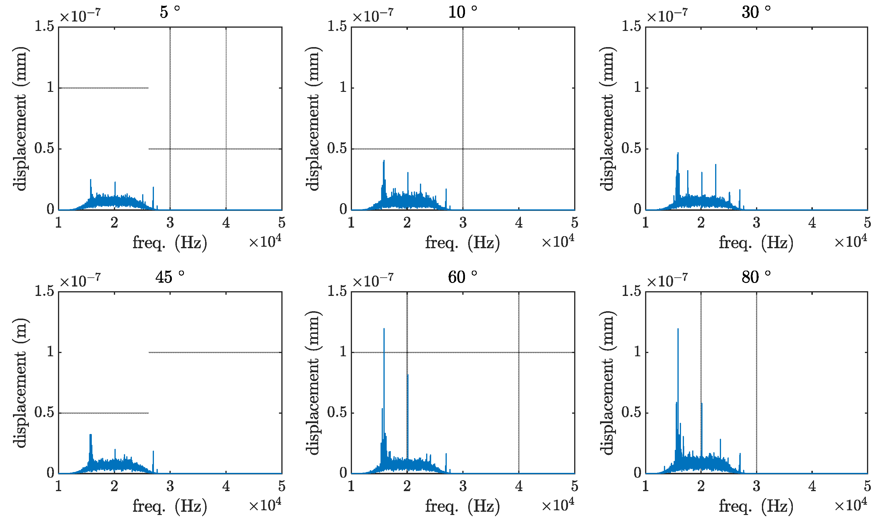
The out-of-plane vibration of the plate (the z-axis) is illustrated in
Figure 3. The maximum vibration level from the plate was recorded at 60 degrees and the minimum at 5 degrees. The observed amplification of vibration at a 60-degree angle could potentially be attributed to the reflection of contactless vibration from the first plate to the second plate. This reflection results in a higher overall vibration compared to the 80-degree angle configuration. Additional frequency components present in the output signal apart from the fundamental frequency are referred to as harmonics which are integer multiples of the fundamental frequency. They arise due to factors such as non-linearities, mechanical resonance, and impedance mismatches
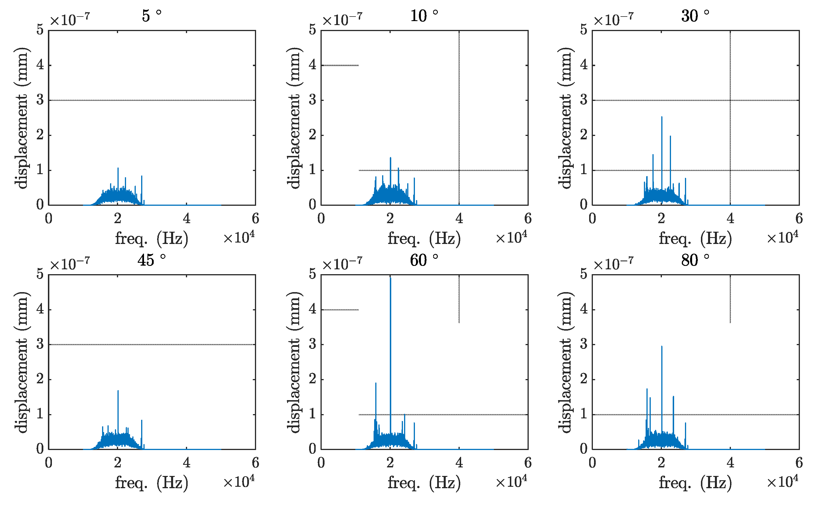
The plate response under the contactless excitation for the x-axis, parallel to the direction of excitation, is plotted in
Figure 4. The maximum vibration level from the plate was recorded at 60 degrees and the minimum at 5 degrees. Similar to the previous findings, the maximum level of vibration occurs at a 60-degree angle. This phenomenon is likely attributed to the reflection of vibrations from the first plate to the second plate, leading to an increased overall in-plane vibration compared to the configuration with a 5-degree angle.
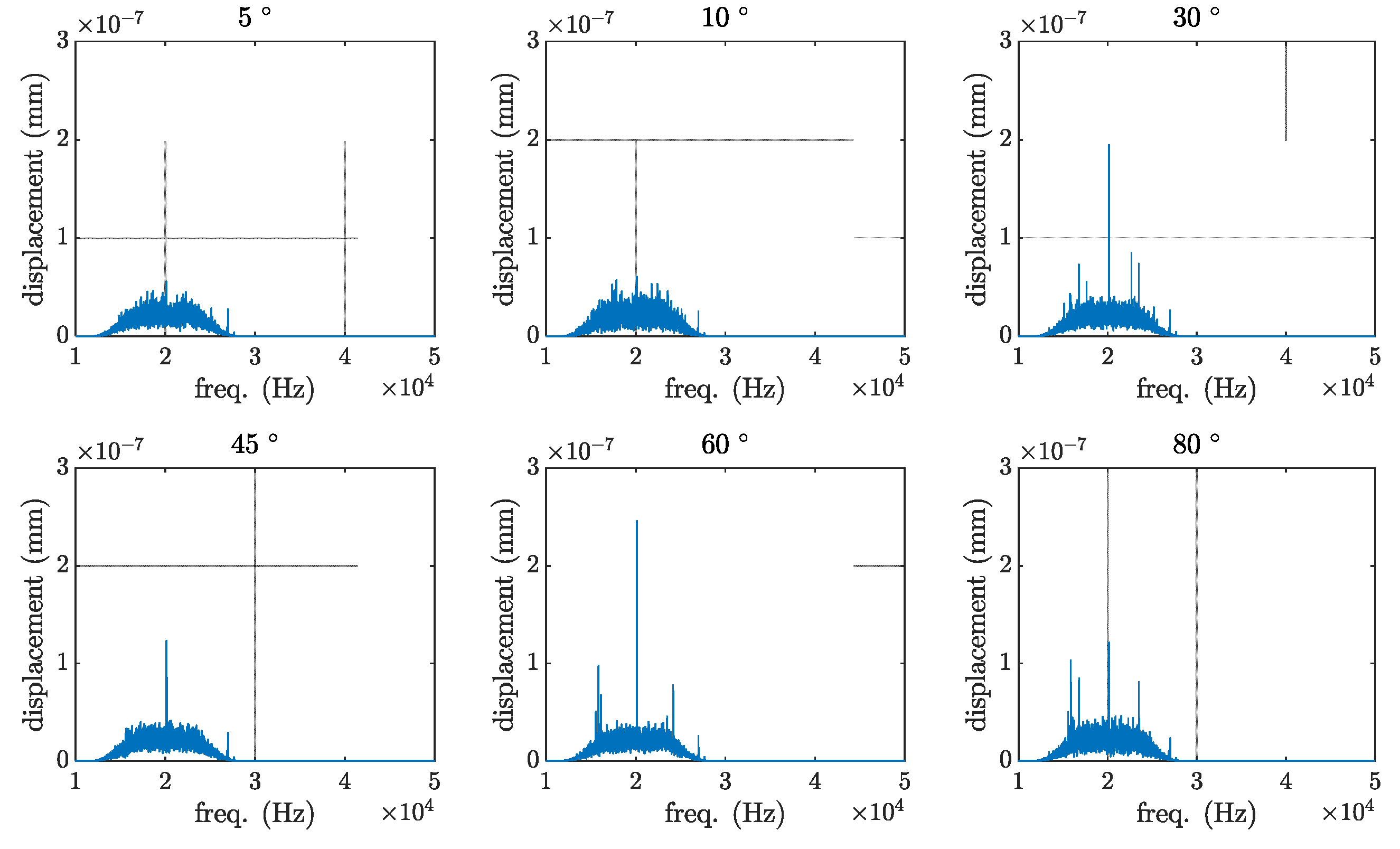
In-plane vibration of the plate in the perpendicular direction to the direction of excitation, the y-axis, is plotted in
Figure 5. As in the previous directions, the highest level of vibration occurs at a 60-degree angle. This could be attributed to the reflection of vibrations from the first plate to the second plate, resulting in an increased overall in-plane vibration compared to the configuration with a 5-degree angle.
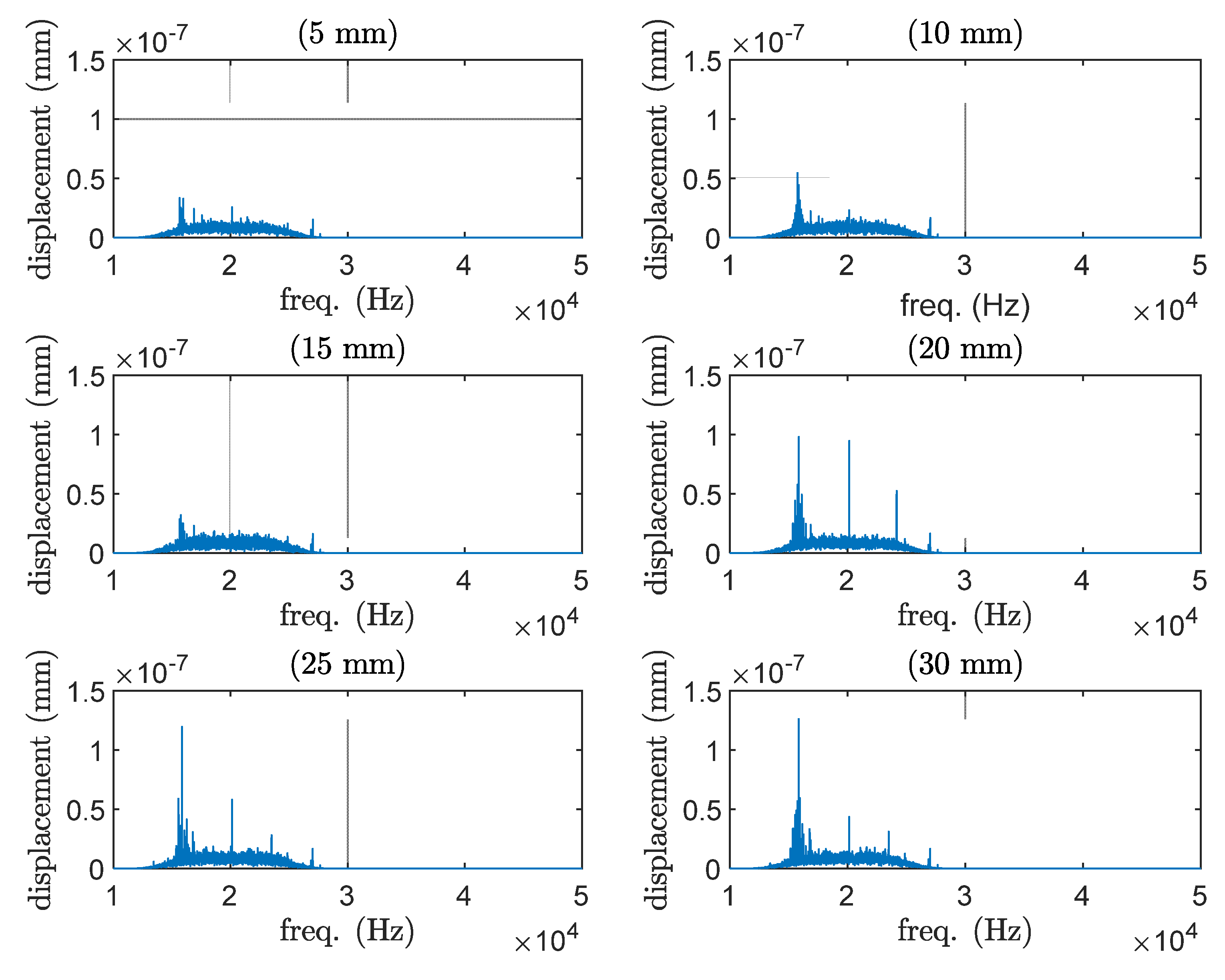
In addition, the study aimed to determine the optimal distance between the tip of the transducer horn and the desired structure, which would result in the highest contactless vibration. To assess this, the effect of varying distances between the two was measured, and the results are presented in
Figure 6. It was found that the vibration level reached its peak when the gap between the structure and the tip of the transducer horn was 20 mm. Subsequently, as the gap increased to 25 mm, the vibration amplitude decreased by half. These findings highlight the importance of the distance between the transducer and the structure in achieving the desired vibration levels.
Depending on the length of the gap, there will be resonance or standing wave field. For this case, the wavelength, , in the dry air can be estimated by , where c is the wave speed (343 m/s) and f is the frequency (20 kHz). Resonance occurs at every distance, where n is an integer number. Consequently, the distances of 4.3 mm, 12.9 mm, 21.5 mm, and so on are expected to yield the highest vibration amplitudes. These distances correspond to the intervals determined by the resonance condition mentioned earlier, where the vibration amplitudes are likely to be maximised.
3. Temperature changes of the HPUT horn
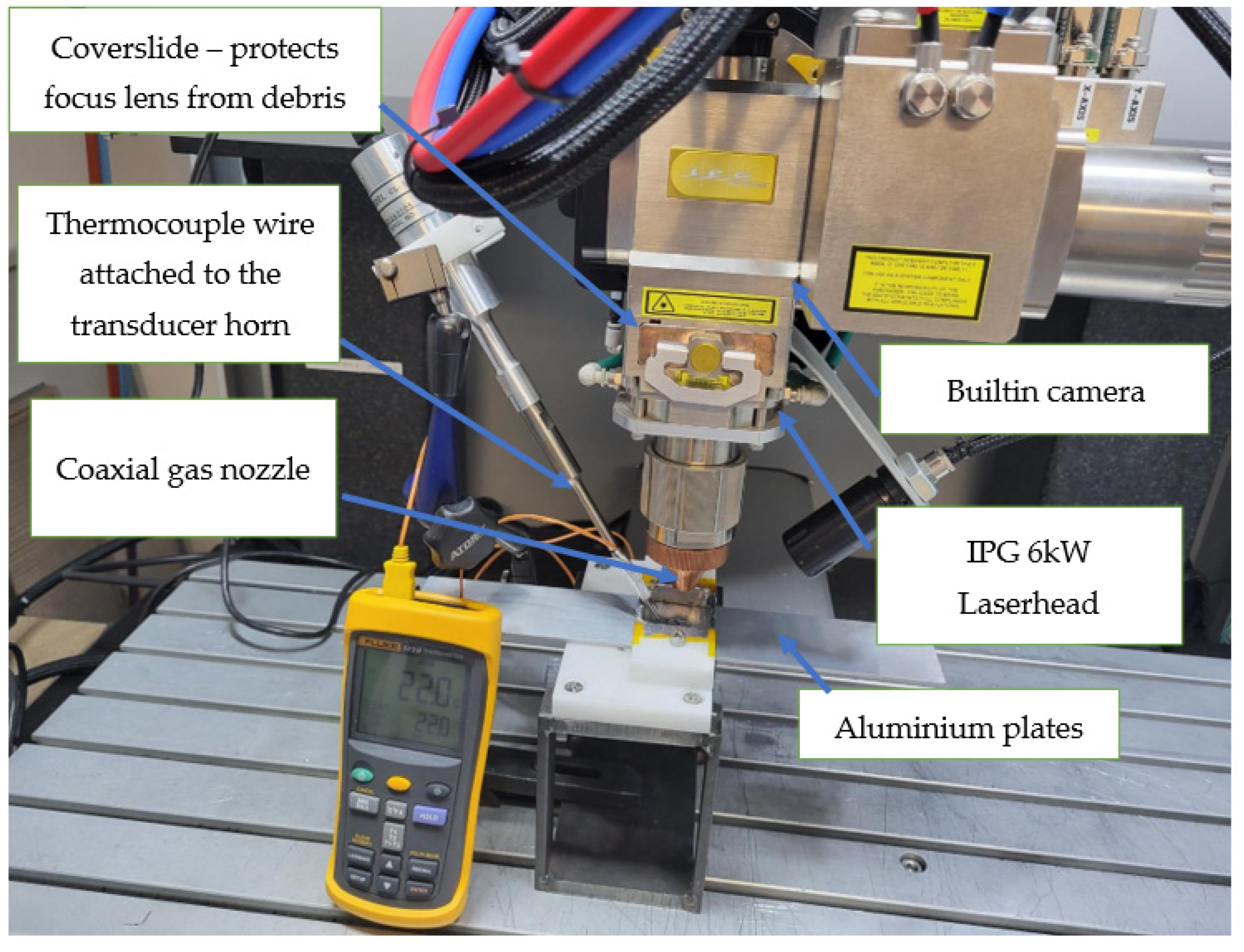
The main objective of this study is to integrate the transducer with a laser welding system and generate contactless vibration during the welding process. In order to achieve this, it is crucial to understand the influence of temperature on the transducer, especially considering that most metals have high melting points. Hence, an experimental study was carried out to find the temperature changes of the transducer horn during the laser operation. Although the transducer horn does not even touch the plate in contactless vibration, it is necessary to investigate its overall temperature during the laser operation to ensure the transducer's functionality and durability under the demanding conditions of welding.
Therefore, the transducer was instrumented with a thermocouple and placed at the desired angle and distance from the area under welding. During this measurement, the transducer was not actively functioning but instead employed solely for the purpose of measuring changes in the temperature of its horn.
An IPG Photonics high-power multimode Ytterbium Fiber Laser system (YLS6000) is used in this experiment. The maximum power is 6000 W and has a fixed wavelength of 1030 nm. The diameter of the fibre is 100 µm, using a multi-axis system with a bed that moves in the y direction and the laser head in the x and z direction, which allows trials to be conducted in a 3D plane. The laser optic is an IPG D50 wobble beam with a lens focal length of 200 mm, a collimation focal length of 200 mm and a spot size of 100 µm. For this experiment, the wobbling system was not activated. The laser's parameters (power and speed) are adjusted according to the requirements of the weld profile. For this investigation, 2 strips of aluminium alloy 1050 were used. The shape of the plates was flat and 2mm thick, with a width and length of 50 mm 120 mm. The two plates would overlap at 50mm, and the weld path would be in the centre. The laser is fired and travels, forming an oval shape commonly used in the industry. The focus would be consistent across all trials; attached to the laser head is a camera with the same focal length as the laser.
Using 2 kW travelling at 2000 mm/min a known laser setting to penetrate through the first layer of 2 mm Aluminium and then partial penetration through the second layer. The partial penetration is seen across many welds in the industry so as to not damage any components. It was found that for a single measurement, the temperature would not go beyond 41 °C. In practice, the laser might be operating for hours. Nevertheless, it is important to note that the maximum temperature reached during the welding process should remain consistent with the findings of this investigation. This is owing to the the same power and speed operation of the laser for welding the plates and the battery head.
The piezoelectric of the transducer itself might get hot if it is set for continuous operation. To address the potential heating of the piezoelectric component of the transducer during continuous operation, Salimi et al. [
29] suggested employing a frequency sweep as a means to indirectly protect the transducer and power generator from potential damage. By utilizing a frequency sweep, the operating conditions of the transducer can be varied, preventing excessive heat build-up and safeguarding the integrity of the transducer and power generator.
Unfortunately, the Q55 transducer's amplifier, called Qsonica, is designed to produce vibrations within a specific frequency range. However, when the transducer is continuously used for a minute, it tends to overheat. Consequently, the output vibrations generated under these overheating conditions are not suitable for ultrasonic-assisted welding applications. The limited control of the transducer's amplifier in terms of signal bandwidth restricts its suitability for extended or industrial-scale welding operations that demand consistent and sustained performance.
4. Impedance testing
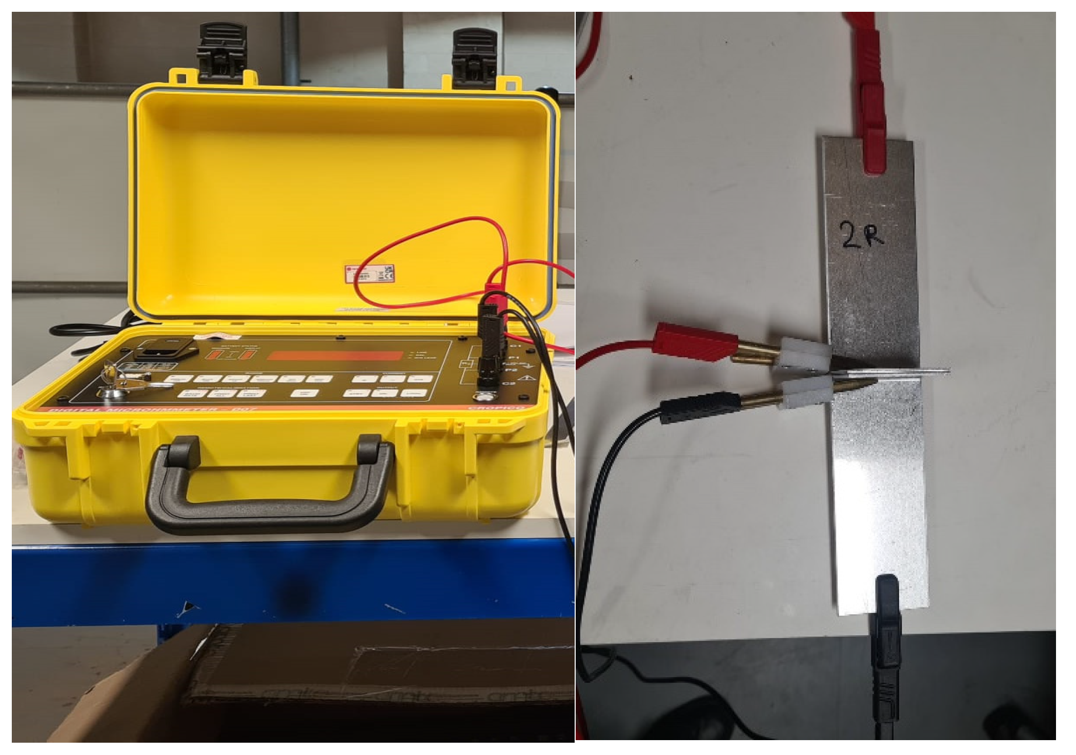
To measure the electrical resistance of lap joints that simulate EV battery connections, the Seaward Cropico DO7 Portable Digital Micro Ohmmeter is used. This measurement aims to find the effect of contactless vibration on reducing the welding resistance compared with non-ultrasound samples.
The Digital Micro Ohmmeter can be used for measuring very low electrical resistances in various applications, including the testing of various applications, including electrical connectors, switches, and fuses. It is commonly used in the automotive, aerospace, and energy sectors, where high accuracy and precision are critical.
The DO7 micro-ohmmeter, illustrated in
Figure 8 operates by passing a small electrical current through the two bottom ends of the welded plate followed by measuring the voltage drop at an area close to the weld. The resistance is then calculated using Ohm's Law (R = V/I), where R is resistance, V is voltage, and I is current. The instrument is designed to provide accurate readings of resistances ranging from less than 1 micro-ohm to 60 ohms, with a resolution of 0.1 micro-ohms.
For comparison, non-ultrasonic welding was carried out. The averaged impedance result for the welding with the contactless vibration-assisted welding was found 18 µΩ while the results associated with the non-ultrasonic was 19.1 µΩ. The impedance measurements were repeated by three times averaging to reduce the inclusion of the error.
5. Current battery head connector welding
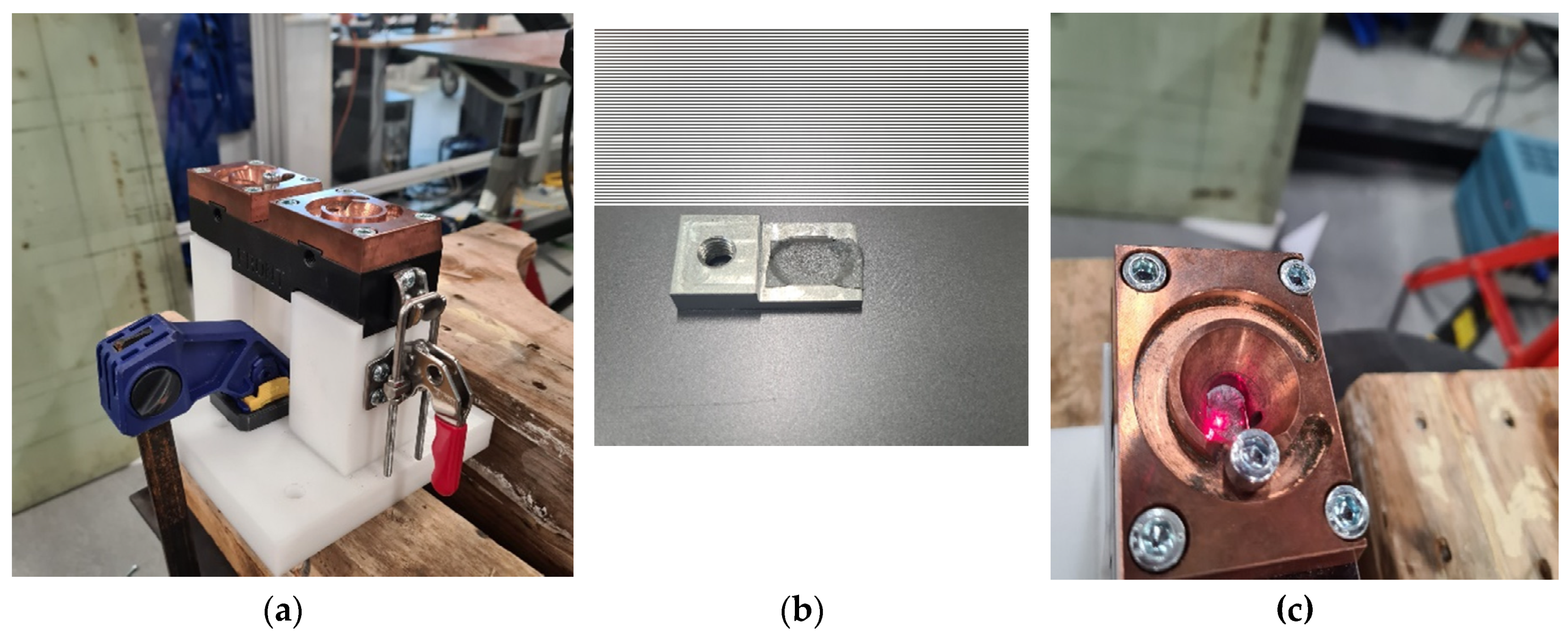
Although contactless excitation is this paper's ultimate aim, it is worth checking the effect of other remote vibrations that can generate mainly shear and compressional waves on the welding impedance value. The current battery head that is used for connecting the battery is lustrated in
Figure 9. A number of places can be used to remotely vibrate the plate to have either shear, or compressional waves dominated. In the welding process, a battery is enclosed within a white plastic cover, as depicted in
Figure 9(a). The top plate, as shown in
Figure 9(b), is then welded to one of the battery terminals, which is composed of an aluminum alloy.
While the vibration level is expected to drop when using contactless vibration compared with contact one [
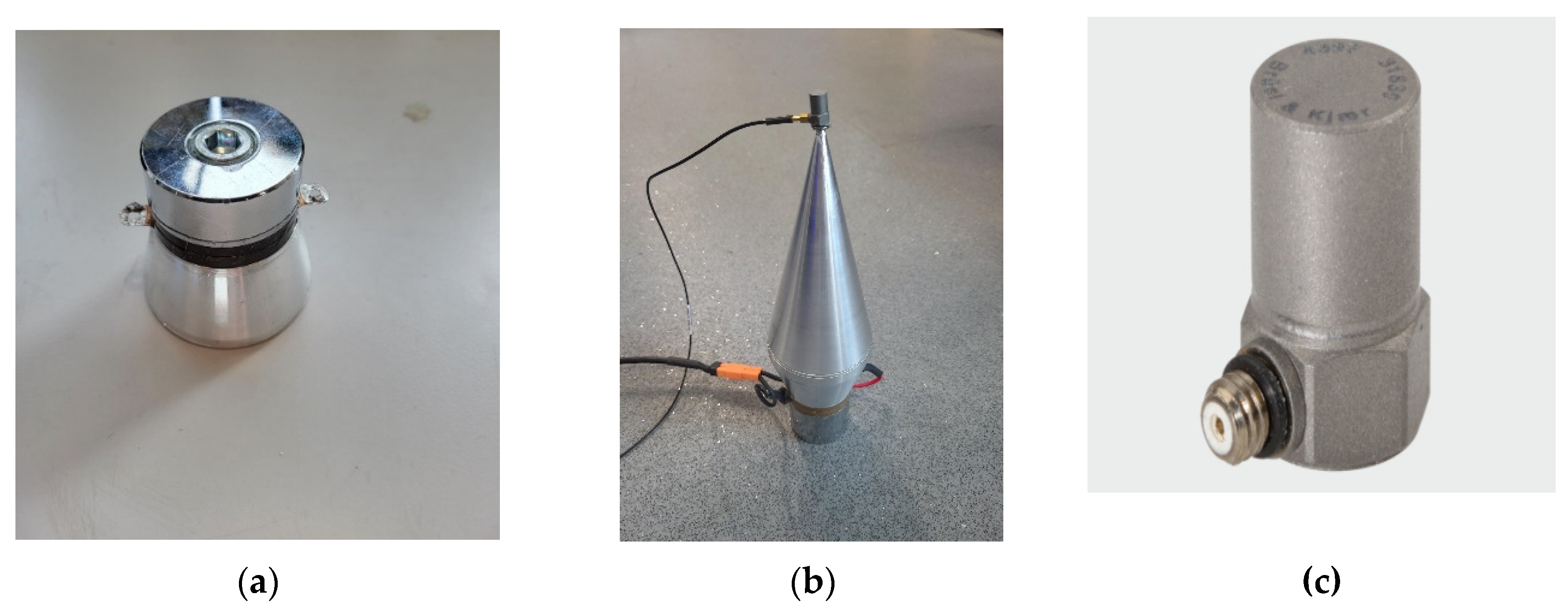
30], it is necessary to find the effect of contact vibration on the welding improvement, in terms of the impedance value. For this purpose, an L shape plate was placed on a holder and the vibration level from a 20 kHz HPUT was measured using contact vibration. Owing to the heating problem explained in section 3, the another transducer with a focused horn is used (see
Figure 10). The horn end tip used in this measurement is slightly bigger than the needle transducer. The industrial transducer with the needle horn is more user-friendly, however, the transducer with the focused horn used in this section is compatible with the amplifier that is developed within Brunel Innovation Centre (BIC). In this case, it is possible to address the heating issue associated with the transducer by increasing the bandwidth of the frequency sweep sine waveform. By expanding the range of frequencies used during the sweep, the transducer can operate more efficiently and mitigate the risk of overheating. This approach allows for a broader spectrum of vibrations, reducing the concentration of energy at the transducer resonance frequency and distributing it more evenly. Before using the HPUT with the focused horn, it was charactrised to find the transducer resonance frequencies.
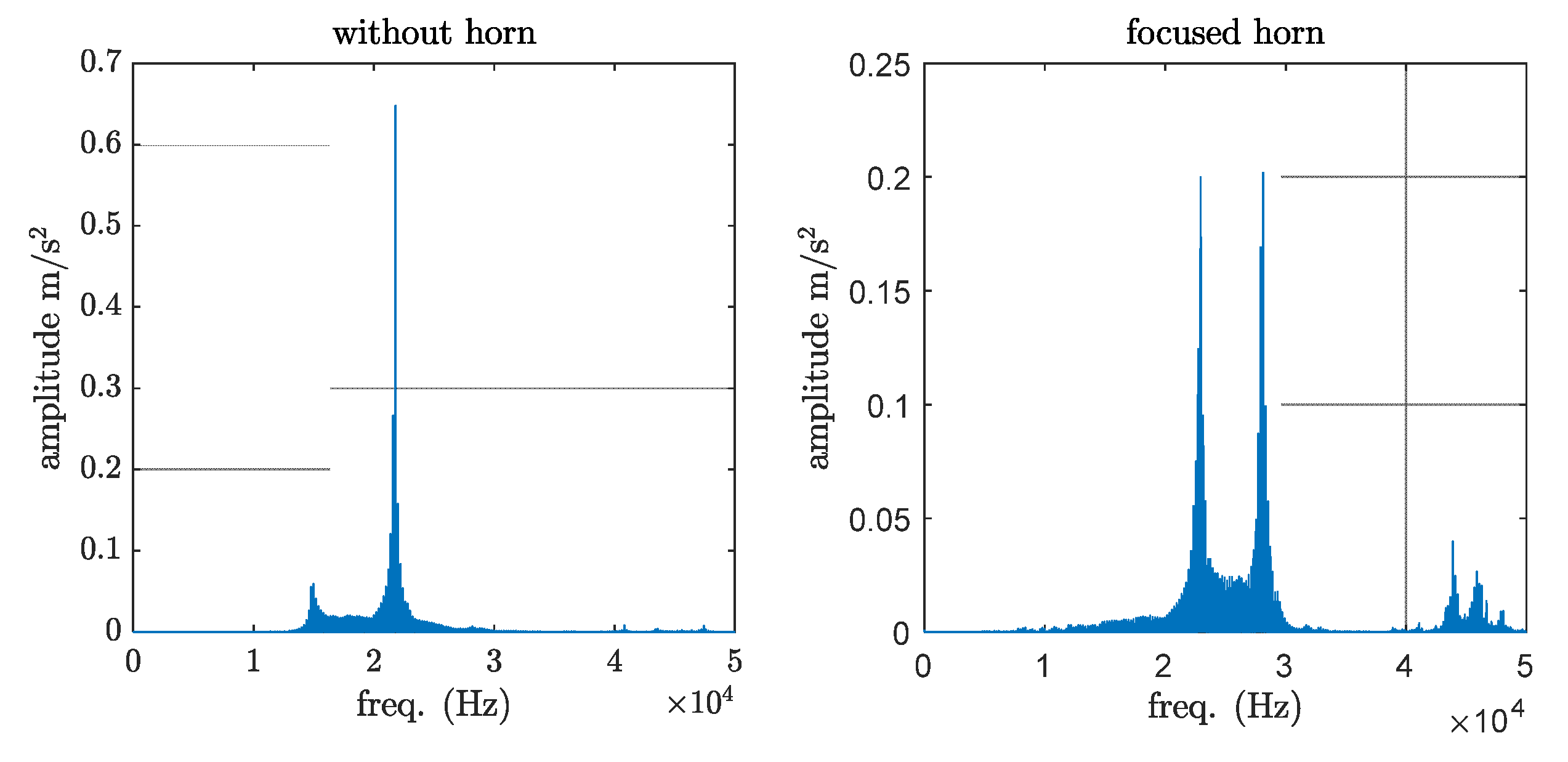
A sweep sine signal, starting from 15 kHz to 30 kHz was sent from the amplified to the transducer followed by measuring the transducer response by the accelerometer. Performing vibration measurement using the laser for this particular case is a time-consuming process due to the small size of the horn tip. It is important to note that the addition of an accelerometer to the transducer introduces additional mass. Despite this limitation, using an accelerometer is considered the most suitable option available. As seen in
Figure 11 the transducer without horns has a single narrow band resonance frequency, at 21.8 kHz region. The power in the focused horn, however, is equally split between two narrow-band frequency regions, at 22.9 kHz and 28.1 kHz.
The contact and contactless vibration output from the focused transducer were measured on the plates, made of aluminium alloy 1050, as shown in
Figure 12. To find the vibration level associated with each measurement, the high-frequency accelerometer type 4397 is used (see
Figure 10(c)) to evaluate plate response. The accelerometer is operating on a single axis, hence to record the plate vibration for the in-plane and out-of-plane excitation, the accelerometer should be oriented in the desired direction. It is expected that the vibration at a zero-degree angle generates an in-plane motion to the plate in the contact and the contactless excitation mode. From the previous assessments made on this particular transducer, it was found that the transducer produces the highest vibration at a 45-degree angle in contact mode. For the contactless excitation, it was found that the maximum vibration is associated with the case where the transducer is positioned at 60 degree with 20 mm distance from the end tip of the horn and the plate.
As illustrated in
Figure 13 the vibration level from the contact excitation is approximately 50 times higher in amplitude compared with the contactless one. Low-intensity ultrasound does not generate any cavitation or shock waves in the molten pool area [
31].
The transducer with 45-degree angle generates shear and compressional waves with approximately the same amplitude. In contrast, the transducer with the 0-degree angle is expected to produce the in-plane or mainly compressional waves. The produced vibration for the contactless excitation was performed at 60 degrees with a 20 mm distance from the molten pool area, on the aluminium alloy 1050 plates.
Figure 14 shows the different HPUT positions for producing shear, compressional and contactless vibration at the welding molten pool area during the laser operation.
The same procedure was followed, as explained in
Section 4 to compare the effect of different wave types, shear and compressional waves, and contactless excitation on the welding quality regarding the impedance value. The averaged impedance value for the in-plane, out-of-plane, and contactless vibration was found 17, 17.8 and 18 µΩ. The impedance measurements were repeated by three times averaging to reduce the inclusion of the error. A slight improvement in the in-plane excitation is associated with the effective propagation of the compressional wave in both fluid and semifluid medium, while the shear wave can only propagate in the fluid medium.
6. Conclusions
This paper aims to demonstrate the impact of low-intensity ultrasound vibration on improving weld quality of aluminum plates, in terms of impedance value. An industrial HPUT that can be integrated into the laser welding system has been characterised to find the optimum distance and angle from the plate to produce the maximum contactless vibration. The optimum distance to exciting the aluminium plates was found to be 20 mm. The optimal angle for both out-of-plane and in-plane displacement was determined to be 60 degrees. The increased vibration amplification observed at a 60-degree angle may be attributed to the reflection of contactless vibrations from the first plate to the second plate. This reflection leads to a higher overall vibration compared to the configuration at other angles.
The effect of different wave types on laser welding improvement was investigated. While contact vibration leads to an acceleration amplitude approximately 50 times higher than contactless vibration, utilising compressional and shear waves to excite the plate results in improvements of 10% and 6% in the impedance value compared with contactless assisted welding, respectively. Using the contactless ultrasound excitation improved 6 % of the welding quality in terms of the impedance value, compared with the non-ultrasonic sample. The lowest impedance value was associated with ultrasonic-assisted welding with the compressional wave, as the pure fluid cannot support shear wave propagation.
The results and discussions presented in this paper suggest that future work could progress in analysing the weld made in this study in terms of microstructure, grain structure, surface quality, aspect ratio and the tensile test.
Author Contributions
Conceptualization, Wamadeva Balachandran and Tat- Hean Gan; Data curation, Ahmed Teyeb, Mohamad Salimi and Samiul Hoque; Funding acquisition, Tat- Hean Gan; Investigation, Phil Carr; Project administration, Phil Carr and Tat- Hean Gan; Supervision, Phil Carr, Wamadeva Balachandran and Tat- Hean Gan; Writing – original draft, Ahmed Teyeb and Mohamad Salimi; Writing – review & editing, Evelyne El Masri, Wamadeva Balachandran and Tat- Hean Gan.
Funding
This research was funded by Innovate UK, grant number: 10018077 . The APC was funded by Brunel University London.
Institutional Review Board Statement
Not applicable.
Informed Consent Statement
Not applicable.
Data Availability Statement
Not applicable.
Conflicts of Interest
The authors declare no conflicts of interest.
References
- Sargent, N.; Jones, M.; Otis, R.; Shapiro, A.A.; Delplanque, J.-P.; Xiong, W. Integration of Processing and Microstructure Models for Non-Equilibrium Solidification in Additive Manufacturing. Metals (Basel) 2021, 11, 570. [Google Scholar] [CrossRef]
- Yuan, L. Solidification Defects in Additive Manufactured Materials. Jom 2019, 71, 3221–3222. [Google Scholar] [CrossRef]
- Manvatkar, V.; De, A.; DebRoy, T. Spatial Variation of Melt Pool Geometry, Peak Temperature and Solidification Parameters during Laser Assisted Additive Manufacturing Process. Materials Science and Technology 2015, 31, 924–930. [Google Scholar] [CrossRef]
- Sheikhi, M.; Ghaini, F.M.; Assadi, H. Prediction of Solidification Cracking in Pulsed Laser Welding of 2024 Aluminum Alloy. Acta Mater 2015, 82, 491–502. [Google Scholar] [CrossRef]
- Kou, S. A Criterion for Cracking during Solidification. Acta Mater 2015, 88, 366–374. [Google Scholar] [CrossRef]
- Wei, H.L.; Elmer, J.W.; DebRoy, T. Origin of Grain Orientation during Solidification of an Aluminum Alloy. Acta Mater 2016, 115, 123–131. [Google Scholar] [CrossRef]
- Sun, T.; Franciosa, P.; Liu, C.; Pierro, F.; Ceglarek, D. Effect of Micro Solidification Crack on Mechanical Performance of Remote Laser Welded AA6063-T6 Fillet Lap Joint in Automotive Battery Tray Construction. Applied Sciences 2021, 11, 4522. [Google Scholar] [CrossRef]
- Sun, T.; Franciosa, P.; Sokolov, M.; Ceglarek, D. Challenges and Opportunities in Laser Welding of 6xxx High Strength Aluminium Extrusions in Automotive Battery Tray Construction. Procedia CIRP 2020, 94, 565–570. [Google Scholar] [CrossRef]
- Yuan, C.; Deng, Y.; Li, T.; Yang, F. Manufacturing Energy Analysis of Lithium Ion Battery Pack for Electric Vehicles. CIRP Annals 2017, 66, 53–56. [Google Scholar] [CrossRef]
- Hannan, M.A.; Hoque, M.M.; Hussain, A.; Yusof, Y.; Ker, P.J. State-of-the-Art and Energy Management System of Lithium-Ion Batteries in Electric Vehicle Applications: Issues and Recommendations. Ieee Access 2018, 6, 19362–19378. [Google Scholar] [CrossRef]
- Casalino, G. Advances in Welding Metal Alloys, Dissimilar Metals and Additively Manufactured Parts. Metals (Basel) 2017, 7, 32. [Google Scholar] [CrossRef]
- Wang, P.; Chen, X.; Pan, Q.; Madigan, B.; Long, J. Laser Welding Dissimilar Materials of Aluminum to Steel: An Overview. The International Journal of Advanced Manufacturing Technology 2016, 87, 3081–3090. [Google Scholar] [CrossRef]
- Kolařík, L.; Janovec, J.; Kolaříková, M.; Nachtnebl, P. Influence of Diffusion Welding Time on Homogenous Steel Joints. Procedia Eng 2015, 100, 1678–1685. [Google Scholar] [CrossRef]
- Tathgir, S.; Rathod, D.W.; Batish, A. A-TIG Welding Process for Enhanced-Penetration in Duplex Stainless-Steel: Effect of Activated Fluxes. Materials and Manufacturing Processes 2019, 34, 1659–1670. [Google Scholar] [CrossRef]
- Kah, P.; Rajan, R.; Martikainen, J.; Suoranta, R. Investigation of Weld Defects in Friction-Stir Welding and Fusion Welding of Aluminium Alloys. International Journal of Mechanical and Materials Engineering 2015, 10, 1–10. [Google Scholar] [CrossRef]
- Manitsas, D.; Andersson, J. Hot Cracking Mechanisms in Welding Metallurgy: A Review of Theoretical Approaches. In In Proceedings of the MATEC Web of Conferences; EDP Sciences; 2018; Volume 188, p. 03018. [Google Scholar]
- Yin, L.; Zhu, C.; Xu, J.; Zhao, H.; Qiu, J.; Wang, H.; Liu, K. Dynamic Impedance Analysis of Intestinal Anastomosis during High-Frequency Electric Field Welding Process. Sensors 2022, 22, 4101. [Google Scholar] [CrossRef]
- Wang, Z.; Gao, J.; Bilal, H.M.; Luo, J.; Li, X. Impedance Compensation of the Welding Area of the RF Connector and Microstrip Line. In Proceedings of the 2018 10th International Conference on Communications, Circuits and Systems (ICCCAS); IEEE; 2018; pp. 190–194. [Google Scholar]
- Sun, Q.J.; Cheng, W.Q.; Liu, Y.B.; Wang, J.F.; Cai, C.W.; Feng, J.C. Microstructure and Mechanical Properties of Ultrasonic Assisted Underwater Wet Welding Joints. Mater Des 2016, 103, 63–70. [Google Scholar] [CrossRef]
- Lei, Z.; Bi, J.; Li, P.; Guo, T.; Zhao, Y.; Zhang, D. Analysis on Welding Characteristics of Ultrasonic Assisted Laser Welding of AZ31B Magnesium Alloy. Opt Laser Technol 2018, 105, 15–22. [Google Scholar] [CrossRef]
- Liu, J.; Zhu, H.; Li, Z.; Cui, W.; Shi, Y. Effect of Ultrasonic Power on Porosity, Microstructure, Mechanical Properties of the Aluminum Alloy Joint by Ultrasonic Assisted Laser-MIG Hybrid Welding. Opt Laser Technol 2019, 119, 105619. [Google Scholar] [CrossRef]
- Teyeb, A.; Silva, J.; Kanfoud, J.; Carr, P.; Gan, T.-H.; Balachandran, W. Improvements in the Microstructure and Mechanical Properties of Aluminium Alloys Using Ultrasonic-Assisted Laser Welding. Metals (Basel) 2022, 12, 1041. [Google Scholar] [CrossRef]
- Teyeb, A.; Salimi, M.; El Masri, E.; Balachandran, W.; Gan, T.-H. Analytical Simulation of the Microbubble Collapsing in a Welding Fusion Pool. Materials 2023, 16, 410. [Google Scholar] [CrossRef] [PubMed]
- Zuo, Y.Y.; Gong, P.; Ji, S.D.; Li, Q.H.; Ma, Z.W.; Lv, Z. Ultrasound-Assisted Friction Stir Transient Liquid Phase Spot Welded Dissimilar Copper-Aluminum Joint. J Manuf Process 2021, 62, 58–66. [Google Scholar] [CrossRef]
- Ma, Z.; Jin, Y.; Ji, S.; Meng, X.; Ma, L.; Li, Q. A General Strategy for the Reliable Joining of Al/Ti Dissimilar Alloys via Ultrasonic Assisted Friction Stir Welding. J Mater Sci Technol 2019, 35, 94–99. [Google Scholar] [CrossRef]
- Ahmadnia, M.; Seidanloo, A.; Teimouri, R.; Rostamiyan, Y.; Titrashi, K.G. Determining Influence of Ultrasonic-Assisted Friction Stir Welding Parameters on Mechanical and Tribological Properties of AA6061 Joints. The International Journal of Advanced Manufacturing Technology 2015, 78, 2009–2024. [Google Scholar] [CrossRef]
- Chen, Q.; Lin, S.; Yang, C.; Fan, C.; Ge, H. Grain Fragmentation in Ultrasonic-Assisted TIG Weld of Pure Aluminum. Ultrason Sonochem 2017, 39, 403–413. [Google Scholar] [CrossRef]
- Wolflabs QSONICA - Q55. Available online: https://www.wolflabs.co.uk/laboratory-products/sonicators-probe-type/10335692 (accessed on 20 May 2023).
- Salimi, M.; Livadas, M.; Teyeb, A.; El Masri, E.; Gan, T.-H. Biofouling Removal Using a Novel Electronic System for Driving an Array of High Power Marinised Transducers. Applied Sciences 2023, 13, 3749. [Google Scholar] [CrossRef]
- Baù, M.; Ferrari, V.; Marioli, D.; Sardini, E.; Serpelloni, M.; Taroni, A. Contactless Excitation and Readout of Passive Sensing Elements Made by Miniaturized Mechanical Resonators. In Proceedings of the SENSORS, 2007 IEEE.; IEEE; 2007; pp. 36–39. [Google Scholar]
- Lentacker, I.; De Cock, I.; Deckers, R.; De Smedt, S.C.; Moonen, C.T.W. Understanding Ultrasound Induced Sonoporation: Definitions and Underlying Mechanisms. Adv Drug Deliv Rev 2014, 72, 49–64. [Google Scholar] [CrossRef]
Figure 1.
(a) The Q55 transducer with (b) the power amplifier. The needle horn can be screwed into the transducer.
Figure 1.
(a) The Q55 transducer with (b) the power amplifier. The needle horn can be screwed into the transducer.
Figure 2.
The plate configuration, made of aluminium alloy 1050, for vibration measurement in the three orthogonal directions.
Figure 2.
The plate configuration, made of aluminium alloy 1050, for vibration measurement in the three orthogonal directions.
Figure 3.
The plate vibration in the vertical direction, the z-axis, increases the transducer angle from approximately 5 ⁰ to 80 ⁰.
Figure 3.
The plate vibration in the vertical direction, the z-axis, increases the transducer angle from approximately 5 ⁰ to 80 ⁰.
Figure 4.
The plate vibration in the horizontal direction, the x-axis, increases the transducer angle from approximately 5 ⁰ to 80 ⁰.
Figure 4.
The plate vibration in the horizontal direction, the x-axis, increases the transducer angle from approximately 5 ⁰ to 80 ⁰.
Figure 5.
The plate vibration in the horizontal direction, the y-axis, by increasing the transducer angle from approximately 5 ⁰ to 80 ⁰.
Figure 5.
The plate vibration in the horizontal direction, the y-axis, by increasing the transducer angle from approximately 5 ⁰ to 80 ⁰.
Figure 6.
The effect of the distance between the tip of the transducer horn and the structure on the contactless vibration specifically in the vertical direction, referred to as the z-axis.
Figure 6.
The effect of the distance between the tip of the transducer horn and the structure on the contactless vibration specifically in the vertical direction, referred to as the z-axis.
Figure 7.
Experimental configuration to record temperature changes of the horn due to the operation of the laser welding device.
Figure 7.
Experimental configuration to record temperature changes of the horn due to the operation of the laser welding device.
Figure 8.
The welding is applied in the middle of two L-shaped plates and the impedance analysis is applied to two sides of the welded plate.
Figure 8.
The welding is applied in the middle of two L-shaped plates and the impedance analysis is applied to two sides of the welded plate.
Figure 9.
The battery plate holder (a) used for connecting the plate to the battery head (b) the plate inside the battery head connector that will be welded to the battery head, (c) the top view from the battery head connector.
Figure 9.
The battery plate holder (a) used for connecting the plate to the battery head (b) the plate inside the battery head connector that will be welded to the battery head, (c) the top view from the battery head connector.
Figure 10.
Figure 10. The 20 kHz transducer used for further investigation. (a) A Plain transducer, (b) transducer with an accelerometer attached to the its end tip and (c) a high-frequency accelerometer, type 4397.
Figure 10.
Figure 10. The 20 kHz transducer used for further investigation. (a) A Plain transducer, (b) transducer with an accelerometer attached to the its end tip and (c) a high-frequency accelerometer, type 4397.
Figure 11.
Figure 11. The spectrum of the transducer with and without focused horn.
Figure 11.
Figure 11. The spectrum of the transducer with and without focused horn.
Figure 12.
Figure 12. The experimental configuration generates (a) contact, (b) contactless vibration at approximately 0 degrees and (c) contactless vibration at 45-degree angle.
Figure 12.
Figure 12. The experimental configuration generates (a) contact, (b) contactless vibration at approximately 0 degrees and (c) contactless vibration at 45-degree angle.
Figure 13.
The vibration output from the contact, contactless excitation, and contactless excitation at a 45-degree angle.
Figure 13.
The vibration output from the contact, contactless excitation, and contactless excitation at a 45-degree angle.
Figure 14.
Ultrasound vibration-assisted welding using (a) shear, (b) compressional and (c) contactless vibration.
Figure 14.
Ultrasound vibration-assisted welding using (a) shear, (b) compressional and (c) contactless vibration.
|
Disclaimer/Publisher’s Note: The statements, opinions and data contained in all publications are solely those of the individual author(s) and contributor(s) and not of MDPI and/or the editor(s). MDPI and/or the editor(s) disclaim responsibility for any injury to people or property resulting from any ideas, methods, instructions or products referred to in the content. |
© 2023 by the authors. Licensee MDPI, Basel, Switzerland. This article is an open access article distributed under the terms and conditions of the Creative Commons Attribution (CC BY) license (http://creativecommons.org/licenses/by/4.0/).
