1. Introduction
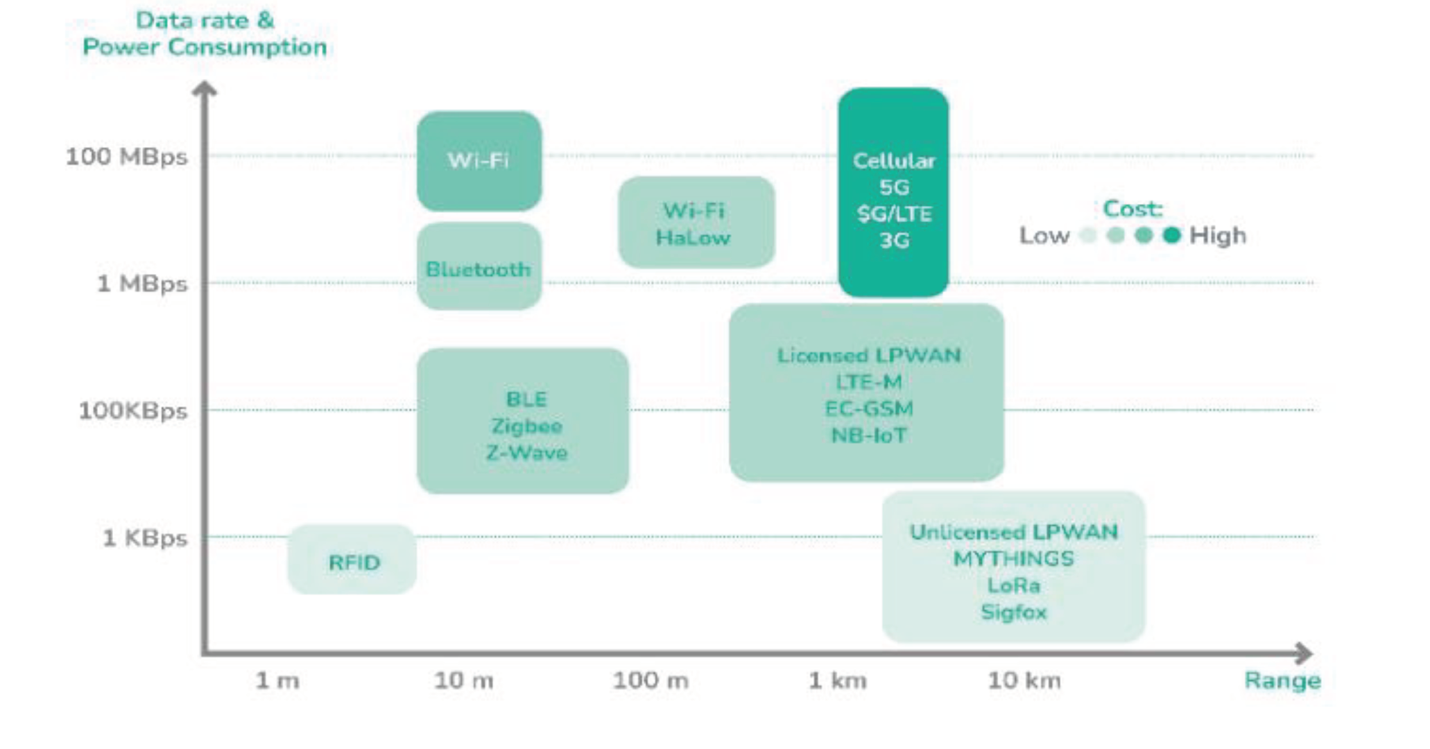
The Internet of Things (IoT) has gained significant attention in various fields, including agriculture, healthcare, asset tracking, and smart cities. Vessel tracking systems were initially used in the shipping industry to locate ships without internet signals, but with technological advancements, they can now be equipped with sensors and communication systems. However, communication range limitations; as shown in
Figure 1, make it challenging to use several tracking applications such as Wi-Fi, Radio Frequency Identification (RFID), and Bluetooth Low Energy (BLE). Therefore, the Global System for Mobile Communication (GSM) is used for wide coverage in good areas. Tracking vessels in certain lake areas also poses a challenge due to signal loss [
1].
With the large number of ton-kilometers transported around the world, it is clear that there is a sizeable market for asset tracking, especially shipping containers. Small assets, packages, equipment, and vehicles that need to be monitored across the logistics industry will help expand this market [
2]. Many monitored assets are monitored across borders and continents, requiring internationally applicable asset connectivity solutions.
In the last decades, both for indoor and outdoor areas, there has been a huge rise in the need for location services [
3]. Industries and researchers alike are interested in the precise location monitoring of assets for both indoor and outdoor use. Before, it was believed that location monitoring was either too expensive for the target market or too difficult to use. The target market and researchers have lately been very interested in both the outside and indoor environments as a result of the development of tracking technologies [
3].
Asset tracking systems have become an integral part of many industries, and different communication technologies are used to enable effective tracking of assets. Two commonly used technologies are RFID and BLE. While these technologies have their advantages, they also have some limitations. As illustrated in
Figure 1, RFID has a limited range, and the assets being tracked need to be in close proximity to the reader [
4]. BLE, on the other hand, can track assets at a longer range, but it has a higher power consumption rate, in addition to the high cost of implementing such systems [
5]. To overcome these limitations, Long Range Wide Area Network (LoRaWAN) technology is being used in asset tracking systems. This technology has a wider range than RFID and BLE and consumes less power than BLE, making it a cost-effective option for asset tracking.
The following sections introduce the implementation of a real-time tracking project using LoRaWAN technology, beginning with its communication principles and hardware analysis, and culminating in the achieved results and conclusions.
2. Communication Principles
2.1. LoRa
Long-Range stands for a proprietary wireless communication method called LoRa. This standard can receive signals even in noisy environments and has a range of about 10 km [
3].
Figure 2 illustrates that LoRa, the physical layer, and LoRaWAN, the upper layer, are the two components of LoRa technology.
LoRa transmits data using unlicensed radio frequency bands (169 MHz, 433 MHz, 868 MHz in Europe, and 915 MHz in North America). LoRa wireless communication technology is based on chirp spread spectrum (CSS) modulation, which uses a frequency chirp that varies linearly in frequency over time to encode information [
6].
2.2. Chirp Spread Spectrum (CSS) modulation
Chirp spread spectrum (CSS) modulation technique is the basis of LoRa technology [
7]. Because of its long range and immunity to interference, chirp spread spectrum has been used for military and space communications since the 1940s [
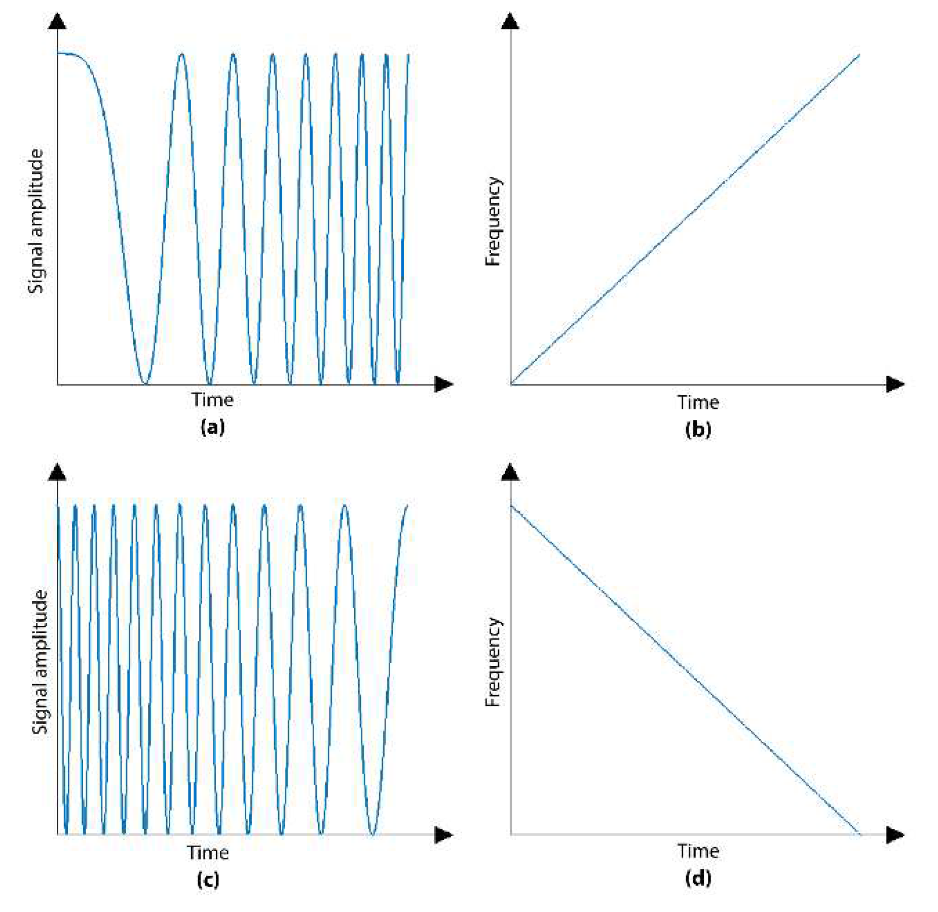
6]. A signal transmitted in a spread spectrum system is spread over a wide frequency band, much wider than the minimum bandwidth required to transmit data. As shown in
Figure 3, LoRa modulation spreads the signal across the spectrum by creating a chirped signal or signals that linearly increase (up-chirp) or decrease (down-chirp) in frequency over time. The rate at which the frequency of each chirp is changed is known as the spreading factor (SF) or chirp data rate. The bandwidth of these chirp symbols is the same as the spectral bandwidth of the signal. Each chirp symbol carries 7 to 12 SF-encoded bits. SF affects transmission time (also called airtime), which affects energy consumption, transmission range, and data rate. Therefore, it determines the amount of redundant data spread across the transmission. A higher spreading factor means more redundant information is sent, which increases the range but reduces the data rate [
6].
2.3. LoRaWAN Protocol
LoRaWAN (Long Range Wide Area Network) is a MAC (Media Access Control) protocol designed for Wide Area Networks (WAN) and Internet of Things (IoT), as shown in
Figure 2. Developed by the LoRa Alliance, a non-profit industry association, it enables low-cost, low-power, long-distance, bi-directional communication of small amounts of data [
6].
In a LoRaWAN network, communication takes place between end devices and gateways. End devices are typically low-power sensors or actuators placed in the field and used to collect data or perform some control function. LoRaWAN end nodes are divided into three categories based on their ability to communicate with the gateway and power supply. The most common type is Class A, which is the most energy efficient, uses a two-way communication protocol, and spends most of its time in sleep mode. Class B nodes have the same protocol as Class A but can receive downlink messages at scheduled times by synchronizing with beacon signals. Class C nodes are the most responsive because they continuously wait for downlink messages, but consume more power. They are ideal for applications that require real-time response, such as remote control and surveillance systems [
8]. They use radio frequency (RF) signals to communicate with the gateway. The gateway is then connected to the Internet and used to transfer data from end devices to network servers [
7].
LoRaWAN is designed for high scalability, allowing a single network to support a large number of end devices. It is also designed for security, with multiple layers of encryption and authentication built into the protocol to protect against unauthorized access [
7].
3. IoT loRaWAN-based system architecture
LoRa is considered a wide-area network solution and is gaining popularity for its ability to cover long distances and consume minimal power, making it suitable for IoT applications. Even major telecom companies are deploying LoRa networks, but anyone can set up a network since LoRa operates in the open spectrum. LoRa Networks are deployed in a star-of-stars topology, A typical LoRa network consists of four components: end nodes, gateways, a network server, and an application server [
9].
LoRa communication typically begins with end nodes communicating with available gateways in the same area of these devices. Connect your assets to the gateway using the LoRa wireless communication method. A gateway acts as a backhaul, allowing data to travel to other devices. On the other hand, it is a gateway to network servers via the TCP/IP communication protocol (Transmission Control Protocol/Internet Protocol). Incoming data for an asset is displayed through an application that connects to a network server through an application programming interface (API). These are all part of the LoraWAN protocol [
9]. As shown in
Figure 4.
3.1. Embedded System Structure
A LoRaWAN system is an embedded system that consists of multiple components that work together to enable long-range, low-power communication between end nodes and gateways. The system’s embedded structure includes the hardware and software components of both the end nodes and the gateways.
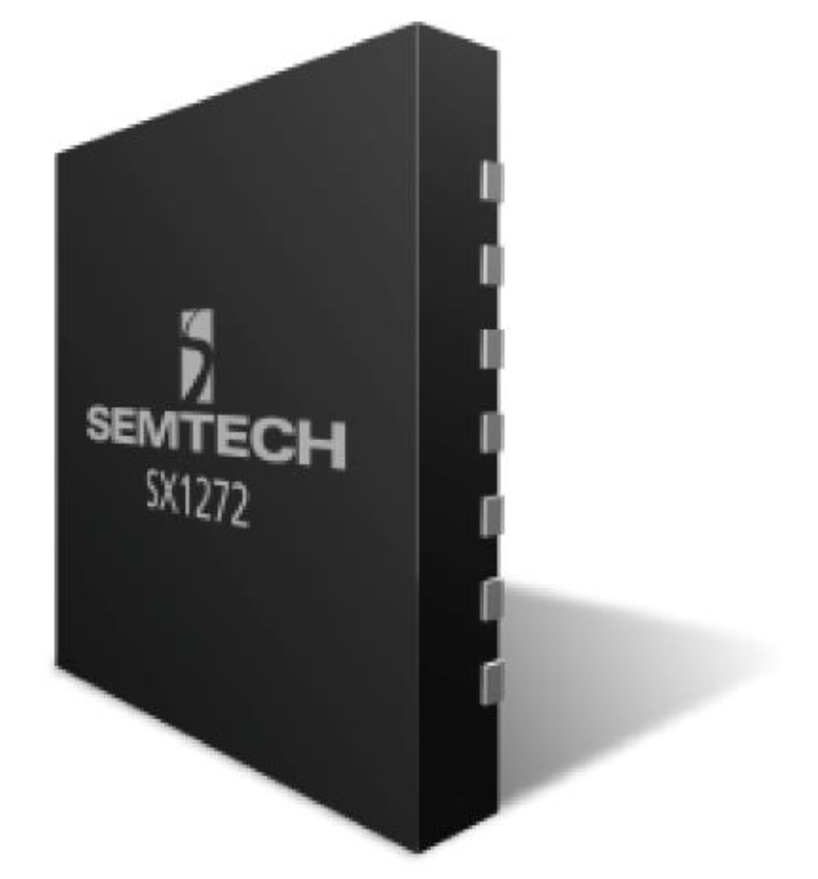
The end node typically includes a microcontroller such as the STM32 series from STMicroelectronics, a LoRa transceiver chip, and various sensors or actuators. Semtech’s LoRa transceiver chips; one example of this is demonstrated in
Figure 5, are commonly used for their high performance and low power consumption such as SX1276x series, SX127x, and LLCC68 transceiver chips [
10].
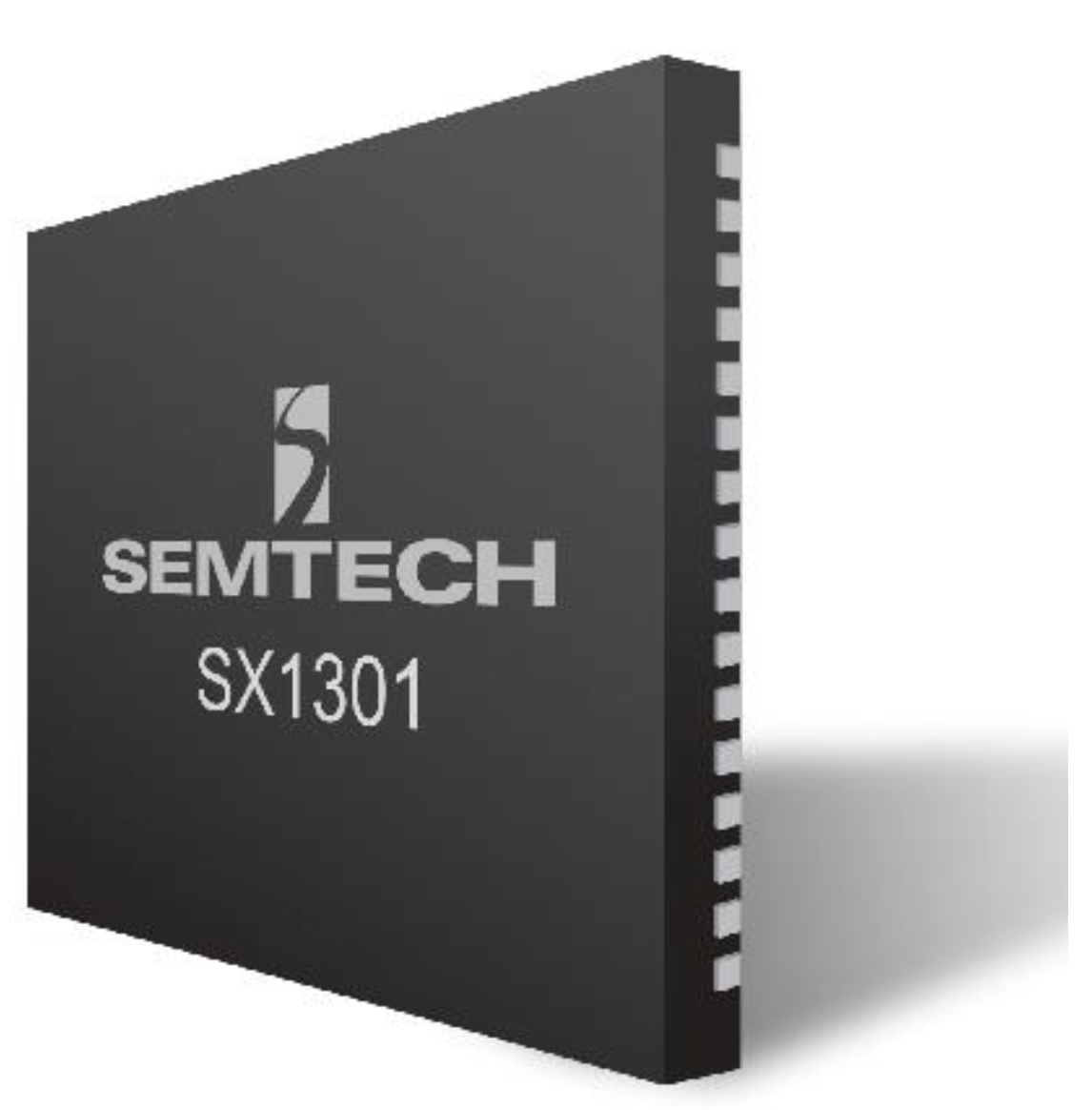
The gateway, on the other hand, contains a computer board such as Raspberry Pi 3B+, a LoRa concentrator such as SX130x series;
Figure 6 provides an example of this LoRa concentrator, which has the ability to build scalable, multi-channel, high-capacity, gateways; this series was manufactured by Semtech company, and a network interface. The concentrator board is responsible for receiving and transmitting LoRa signals while the computer board is used to control and manage the gateway [
10].
Both the end nodes and the gateways run embedded software that controls their operation, enabling them to communicate with each other using the LoRaWAN protocol [
2].
3.2. System Specifications
The success of an IoT system depends on the choice of network architecture and protocol. LoRaWAN, as a promising technology for long-range and low-power wireless communication, has gained significant attention in the IoT industry and understanding the specifications and features of LoRaWAN is essential for developing and deploying a robust IoT solution that meets the system’s specific requirements [
11].
LoRaWAN is designed to provide long-range communication capability, allowing devices to communicate over distances of up to 15 km in rural areas and up to 2 km in urban areas. It is optimized for low-power devices, allowing them to operate for long periods of time on small batteries, and is designed to be a low-cost solution for IoT applications, making it suitable for use in a wide range of applications. LoRaWAN provides end-to-end encryption to ensure secure communication between devices and is designed to be a scalable solution, allowing it to support a large number of devices and applications. Additionally, LoRaWAN allows devices to communicate in both directions, enabling them to send and receive data. The network architecture of LoRaWAN includes gateways, which act as a bridge between the devices and the network, and a network server, which manages the communication between devices. Finally, LoRaWAN supports multiple channels, allowing devices to communicate on different frequencies and reducing the likelihood of interference [
11].
4. Presented Tracking System
In this paper, a prototype design and implementation of an IoT LoRaWAN-based real-time asset tracking system will be developed and presented, it will demonstrate the feasibility, effectiveness, and utilization of LoRaWAN technology in providing real-time asset tracking capabilities.
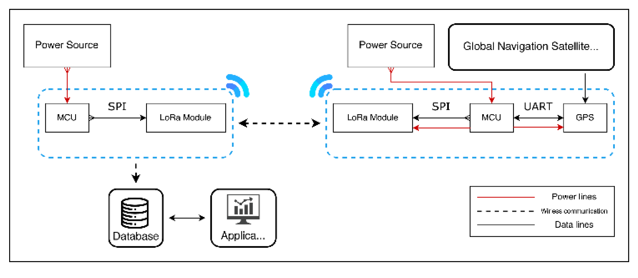
The main structure of the system consists of four major elements represented by the block diagram in
Figure 7. Lora end nodes that are connected to the assets being tracked, Lora gateways that must be in fixed locations to collect data from the end nodes, databases where data collected by the gateways are stored and processed, and application data. Visualize and enable users to monitor and gain insight into their valuable assets.
4.1. Prototype Components
The prototype of the real-time asset tracking system comprises various components, including the ESP32 microcontroller, GPS NEO 6M, TTGO T-Higrow Lora Shield, and LD1086v33 voltage regulator.
The ESP32-WROOM module is a highly capable and versatile system-on-chip (SoC) solution that is particularly well-suited for asset tracking systems. It is based on the ESP32 chip, which boasts a dual-core processor with a clock speed of up to 240MHz, as well as integrated Wi-Fi and Bluetooth connectivity and a host of peripheral interfaces such as UART, SPI, and I2C [
12].
The GPS NEO 6M is an incredibly reliable and efficient receiver (GPS Module) that is perfectly suited for our asset tracking system. With its 50-channel u-blox 6 positioning engine, this device is capable of fast and accurate location tracking with an impressive update rate of up to 5 Hz. The GPS NEO 6M also features an exceptional sensitivity of -162 dBm for tracking and -148 dBm for cold start, ensuring that it can effectively receive and process signals even in low signal strength environments [
13].
The TTGO T-Higrow LoRa Shield is a highly capable function expansion board that has been specifically designed for use in tracking systems. It features a SX1276 LoRa transceiver module that facilitates long-range wireless communication between devices and communicates with the host microcontroller via the Serial Peripheral Interface (SPI), making it highly adaptable to a variety of systems [
14].
LD1086v33 is a voltage regulator integrated circuit (IC) that has a wide input voltage range and is capable of regulating voltages from 1.2 volts to 20 volts, with a maximum output current of 1.5 amps. It regulates the input voltage to 3.3 volts [
15].
4.2. Data Flow Phases
In the Real-Time Asset Tracking System, the data flow can be divided into three phases which are Data collection, data storage, and data visualization phase. Starting at the end node; which was attached to the asset, with the GPS module which continuously receives location data and sends it to the ESP32 microcontroller via UART communication. The ESP32 microcontroller processes the received data and sends it to the TTGO T-Higrow Lora Shield via SPI communication protocol. The Lora Shield then transmits this data wirelessly to the gateway using the LoRaWAN protocol. The gateway receives the data and forwards it to google sheets to be stored and then visualized.
- (1)
Data collection phase: This phase runs throughout the operation of end nodes and gateways, end nodes receive real-time location information via GPS module, send this data to the gateway via LoRa wireless communication technology, and add timestamps. and finally send the data to the database over an outbound internet connection.
- (2)
Data storage phase: During this phase, the location coordinates received from the gateway are saved to Google Sheets. Google Sheets automatically updates with new location data in real time and can handle large amounts of data.
- (3)
Data Visualization phase: The system uses the Google Maps API to display the object’s path on the map. This not only makes data available for users to download using formats such as (.csv, .xlsx), but also shows the current location of the asset and its historical path.
5. Target Platform
This section will provide a detailed overview of the circuit design for both the end node and the gateway, including the schematic diagrams, and the pin connection table. It will also explain the function of each component in the circuit and how they work together to achieve the desired outcome.
5.1. Endnode Circuit Implementation
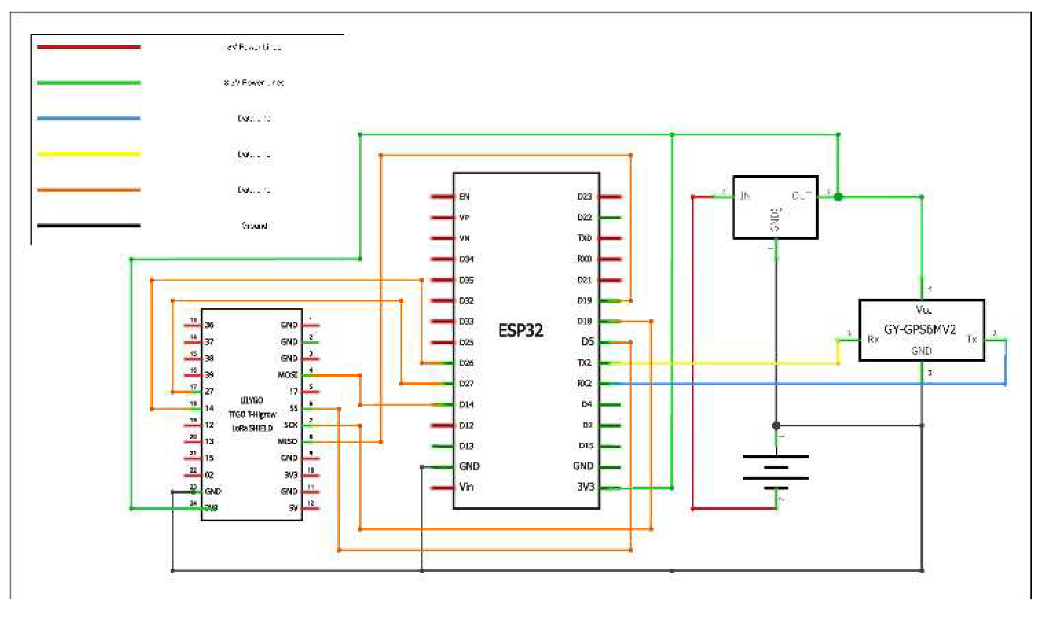
Figure 8 shows the end node circuit, which is composed of an ESP-32 microcontroller which is the backbone of the circuit, GPS Neo 6M which is the GPS module, and the TTGO T-Higrow Lora Shield is the wireless communication module used to communicate with the gateway. these components are powered by two-cell lithium-ion batteries each of 3.7 volts these batteries are connected to a voltage regulator to output the required 3.3 volts to operate the circuit components. The GPS module and the MCU are connected using the Universal Asynchronous Receiver/Transmitter (UART) communication protocol, providing a reliable data transfer between them. The MCU and the Lora module are connected via the Serial Peripheral Interface (SPI) communication protocol, ensuring fast and reliable data transfer.
5.2. Gateway Circuit Implementation
Figure 9 shows the gateway circuit diagram, which is composed of the ESP-32 microcontroller, which acts as the backbone of the circuit, providing the necessary processing power and connectivity for the system’s efficient operation. The wireless communication module used to communicate with the end node is the TTGO T-Higrow Lora Shield. It is connected to the ESP32 microcontroller via the SPI communication protocol, the Lora module receives packets sent from the end node and forwards them to the microcontroller. This enables the microcontroller to establish internet connectivity and upload the data to a Google Sheet database for visualization on a website. The shield operates on 868 MHz frequency and ensures reliable communication between the gateway and the end node. These components are powered by two-cell lithium-ion batteries, each of which provides 3.7 volts. To ensure optimal operation, the batteries are connected to a voltage regulator that outputs the required 3.3 volts to operate the circuit components. The voltage regulator also ensures that the batteries’ voltage output is stable, providing a constant power supply to the circuit. The gateway circuit diagram plays a critical role in the real-time asset tracking system’s operation, ensuring that the system operates efficiently and reliably.
6. Experimental Results
The experimental results section presents the outcomes of testing the Real-time asset tracking system prototype. This section highlights the system’s performance in accurately tracking the location and status of the asset in real time. The experiments conducted aimed to evaluate the system’s efficiency and accuracy under different conditions, including tracking a moving asset and a stationary asset. Additionally, this section discusses the data transmitted from the end node to the gateway, which is crucial for tracking the asset’s location and status. These results will provide insights into the system’s capabilities and potential applications for real-time asset tracking.
The Real-time asset tracking system prototype was tested three times at different locations, and in all tests, the system successfully tracked the end node’s location. During the first test, which took place on February 12th at Banha Governorate, someone carried the asset (end node); which was a back bag, away from the gateway, and the system accurately tracked its location. In the second test, which took place on February 25th at October University for Modern Sciences and Arts (MSA University), the end node was again a backpack carried away from the gateway, and the system accurately tracked its location.
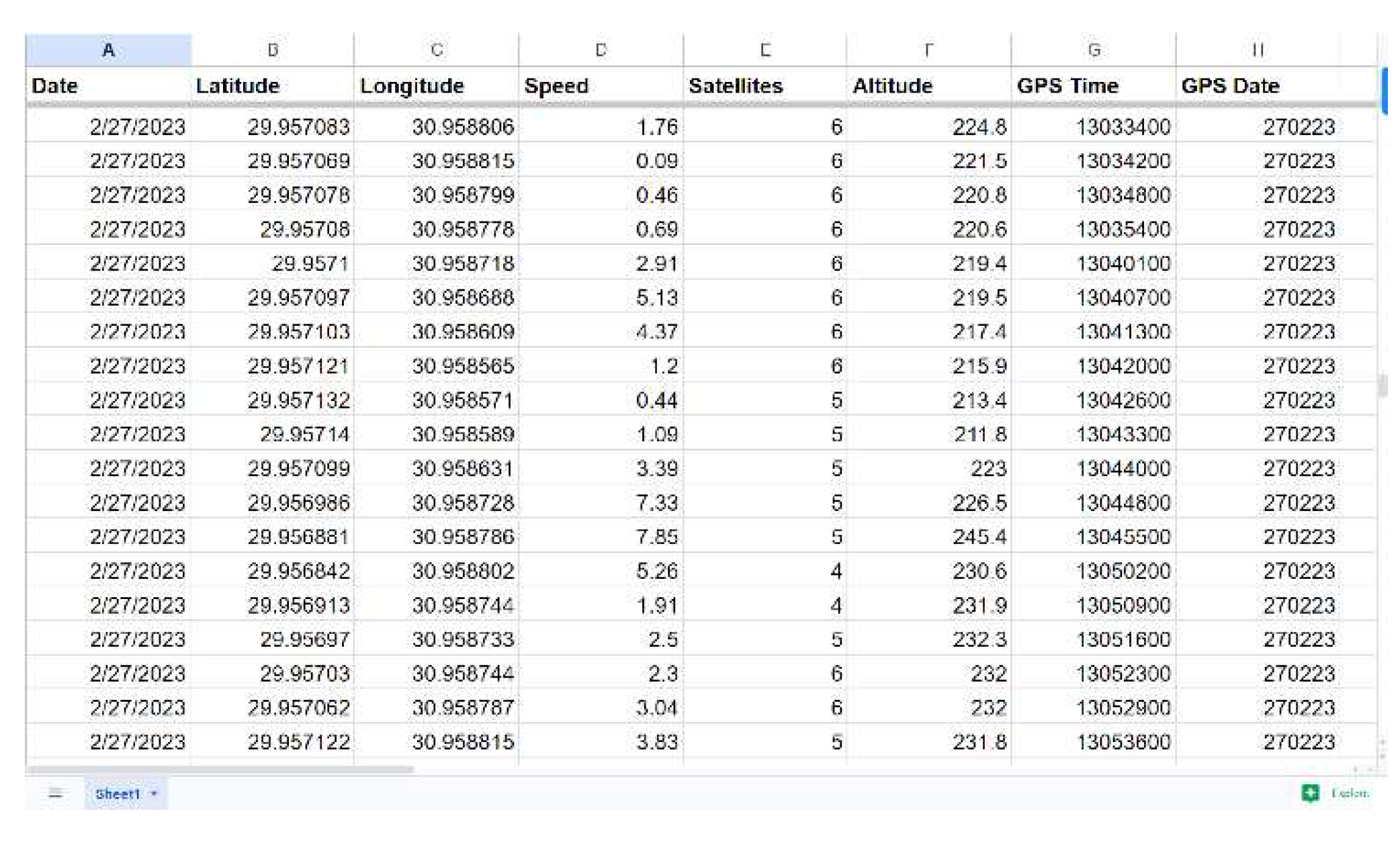
The third test, which also took place at MSA University on February 27th, involved attaching the end node to a moving golf cart, and the system was able to track the golf cart’s location in real time. The data transmitted from the end node to the gateway includes seven parameters: latitude, longitude, speed, number of satellites, altitude, and time and date as shown in
Figure 10.
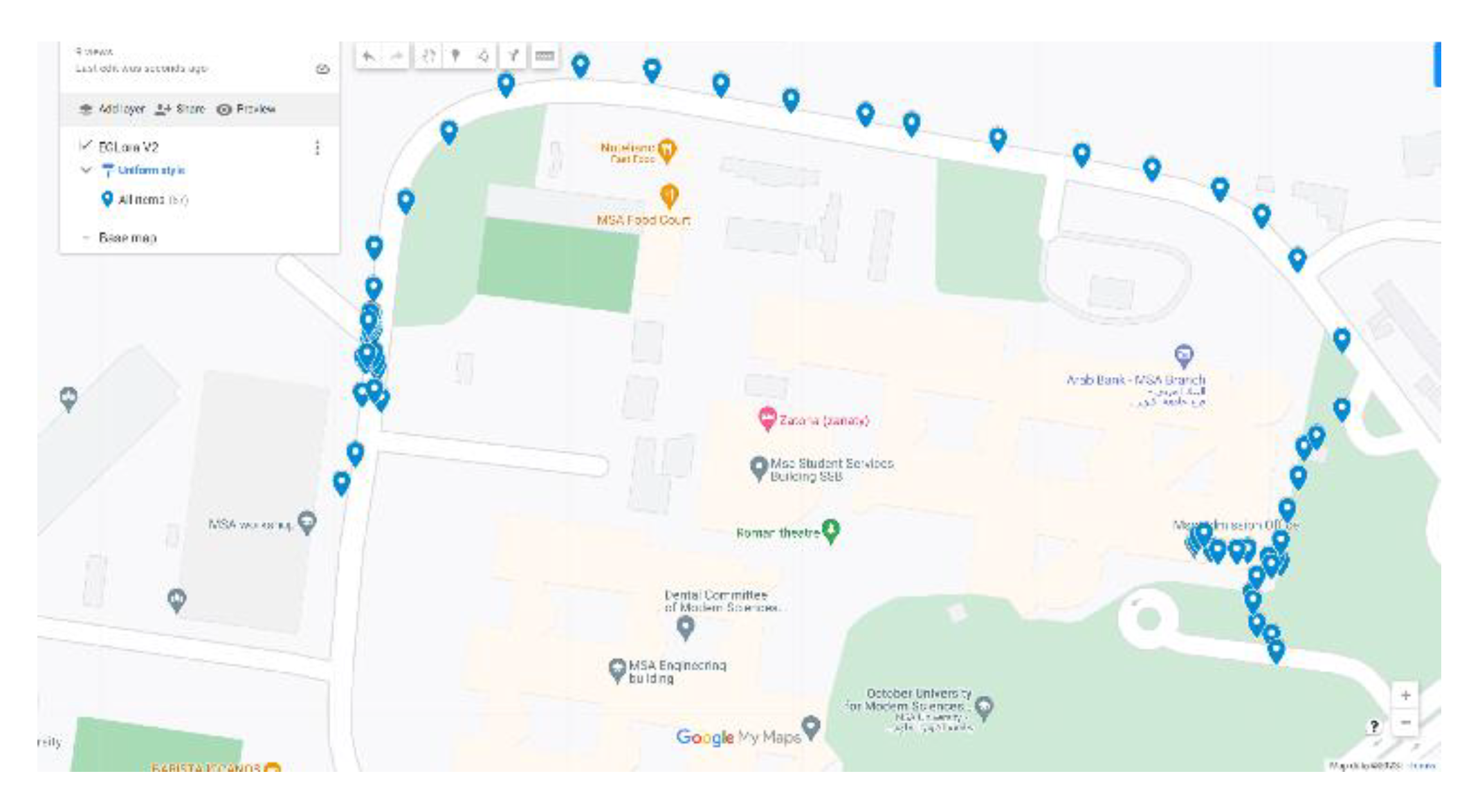
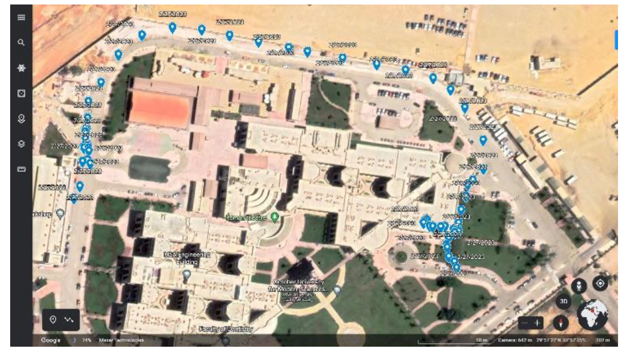
This data is then transmitted to the Google Sheet database for storage and used to produce two maps, a Google Map and a Google Earth Map, to visualize the asset’s position; as illustrated in
Figure 11 and
Figure 12, enabling efficient tracking of its location.
Overall, these tests demonstrated the Real-time asset tracking system prototype’s efficiency and accuracy, indicating its potential for use in a variety of tracking applications.
7. Conclusion
In conclusion, the asset tracking system using LoRaWAN technology is a highly efficient and cost-effective solution for monitoring and managing various types of assets. The long-range capabilities of LoRaWAN allow for the tracking of assets over large distances, while the low-power requirements of the technology help to reduce costs associated with energy consumption. Additionally, the use of LoRaWAN provides a secure and reliable means of transmitting data, ensuring that the asset tracking system is able to function effectively in a variety of environments. Overall, the project has been successful in demonstrating the feasibility of using LoRaWAN technology for asset tracking and has the potential for future development and implementation in a wide range of industries.
This Asset Tracking System aims to provide a reliable, efficient, and cost-effective solution for tracking and monitoring assets remotely, improving operational efficiency, and reducing the risk of asset loss or theft. It has the potential to contribute to the efficient and sustainable management of assets, which aligns with the vision of Egypt for 2030, and the United Nations Sustainable Development Goals (SDGs), such as SDG 9 (Industry, Innovation, and Infrastructure) and SDG 11 (Sustainable Cities and Communities).
References
- Sagala, R. Lubis, H. Sitanggang, R. Sinaga, and S. Hutapea, “Implementation LoRaWAN End Node Tracking,” IOP Conference Series: Earth and Environmental Science, vol. 1083, no. 1, p. 012061, Sep. 2022. [CrossRef]
- “WHY LoRaWAN® IS THE LOGICAL CHOICE FOR ASSET-TRACKING CONNECTIVITY,” resources.lora-alliance.org, Apr. 2020. https://resources.lora-alliance.org/whitepapers/why-lorawan-is-the-logical-choice-for-asset-tracking-connectivity.
- F. Ahmed, M. Phillips, S. Phillips, and K.-Y. Kim, “Comparative Study of Seamless Asset Location and Tracking Technologies,” Procedia Manufacturing, vol. 51, pp. 1138–1145, 2020. [CrossRef]
- Y. S. Chang, M. G. Son, and C. H. Oh, “Design and implementation of RFID based air-cargo monitoring system,” Advanced Engineering Informatics, vol. 25, no. 1, pp. 41–52, Jan. 2011. [CrossRef]
- S. Naik, R. Phadnis, N. Sharma, and M. Parmar, “Real Time Asset Tracking using BLE Beacons,” in IEEE Xplore, Oct. 2019, pp. 1–4. [CrossRef]
- “LoRa and LoRaWAN: A Technical Overview LoRa® and LoRaWAN®: A Technical Overview,” 2019. Available: https://lora-developers.semtech.com/uploads/documents/files/LoRa_and_LoRaWAN-A_Tech_Overview-Downloadable.
- F. Priyanta, F. Golatowski, T. Schulz, and D. Timmermann, “Evaluation of LoRa Technology for Vehicle and Asset Tracking in Smart Harbors,” IECON 2019 - 45th Annual Conference of the IEEE Industrial Electronics Society, vol. 45th, pp. 4221–4228, Oct. 2019. [CrossRef]
- Hakkenberg, “Experimental evaluation of LoRa(WAN) in indoor and outdoor environments,” University of Twente, 2016. Available: http://essay.utwente.nl/71133/.
- L. Khalil, “LoRa-positioning in Malmö compared with GPS: possibilities, power consumption & accuracy,” Dissertation, Malmö universitet/Teknik och samhälle, 2018. Available: http://www.diva-portal.org/smash/record.jsf?pid=diva2%3A1480355.
- LoRa Products, Semtech Co., California, USA, 2022. Accessed: Jan. 3, 2023. [Online]. Available: https://www.semtech.com/uploads/design-support/SEMTECH_LORA_PG_web.pdf.
- M. A. M. Almuhaya, W. A. Jabbar, N. Sulaiman, and S. Abdulmalek, “A Survey on LoRaWAN Technology: Recent Trends, Opportunities, Simulation Tools and Future Directions,” Electronics, vol. 11, no. 1, p. 164, Jan. 2022. [CrossRef]
- ESP32-WROOM-32 Datasheet, Espressif Systems Co., CN, 2023. Accessed: Feb. 9, 2023. [Online]. Available: https://www.espressif.com/sites/default/files/documentation/esp32-wroom-32_datasheet_en.pdf.
- NEO-6, U-blox Co., Thalwil, CH, 2022. Accessed: Feb. 12, 2023. [Online]. Available: https://content.u-blox.com/sites/default/files/products/documents/NEO-6_DataSheet_%28GPS.G6-HW-09005%29.pdf.
- “LILYGO® TTGO T-Higrow LoRa Shield 868Mhz Function Expansion Board - LoRa or GPS - Shenzhen Xin Yuan Electronic Technology Co., Ltd.,” www.lilygo.cn, 2020. http://www.lilygo.cn/prod_view.aspx?TypeId=50060&Id=1309&FId=t3:50060:3.
- LD1086 Datasheet, STMicroelectronics Co., Geneva, CH, 2022. Accessed: Feb. 9, 2023. [Online]. Available: https://www.st.com/resource/en/datasheet/ld1086.pdf.
|
Disclaimer/Publisher’s Note: The statements, opinions and data contained in all publications are solely those of the individual author(s) and contributor(s) and not of MDPI and/or the editor(s). MDPI and/or the editor(s) disclaim responsibility for any injury to people or property resulting from any ideas, methods, instructions or products referred to in the content. |
© 2023 by the authors. Licensee MDPI, Basel, Switzerland. This article is an open access article distributed under the terms and conditions of the Creative Commons Attribution (CC BY) license (http://creativecommons.org/licenses/by/4.0/).
