1. Introduction
With the rapid increase in the number of small uncrewed aircraft vehicles (UAVs), their antenna design is becoming increasingly important to ensure a stable link [
1]. This study addresses an antenna design for light-and-small civil UAV applications in urban areas. Small UAVs tend to be lightweight and small for portability, so they are unsuitable for mounting turntables or large phased-array antennas.
Figure 1 shows the common scenarios of light-and-small civil UAV applications in urban areas where a person holding a remote control operates a quadcopter.
The proposed antenna is mounted below the propeller on the outermost side of the wing of a small UAV, away from large metal conductors, such as printed circuit boards (PCBs) and batteries, in the UAV body. The UAV takes off from the ground, flies vertically above ground objects, and then flies forward to the farthest position. The flight must avoid hitting ground objects, such as people, trees, and buildings, so the UAV must stay above them. The distances between the UAV and the remote control increase as it takes off from the ground, flies vertically above ground objects, and flies forward to the farthest position.
To ensure stable transmission quality and stability, the gain and polarization characteristics of the antenna are determined based on the Friis Transmission Equation [
2]. The antenna must meet the following requirements to reduce interference and provide more antenna gain when the small UAV flies farther in urban areas. First, its
must be equal to or smaller than
to ensure efficient power delivery to the antenna. Second, it must have a small size and low profile to meet the portability and aerodynamic requirements for small UAV applications. Third, it must have stronger radiation below the UAV to reduce interference from rare-use directions. Because the UAV is always above the remote control as it flies away, it is farther away from the remote control than when it was taking off. Fourth, its maximum radiations, the directions of the maximum radiation in each elevation plane, must be below the UAV and between 10° and 30° from the horizontal plane to provide more antenna gain when the small UAV flies farther in urban areas. Finally, due to the boundary condition of the earth’s ground plane, the antenna must have good vertically polarized radiation for long-distance applications.
Although many antenna architectures have been proposed [
3,
4,
5,
6,
7,
8,
9,
10,
11,
12,
13,
14] to meet the requirements for UAV applications, none fully meet the requirements for small UAV applications in urban areas. Due to their small size and lightweight nature, folded dipole antennas have been proposed [
3,
4] for small and compact UAV applications, respectively. The fragmented antenna was proposed [
3], and its overall dimensions and total mass are
at 240 MHz and 18 g (including the matching circuit). A compact electrically tunable VHF antenna [
4] was integrated into the landing gear of a compact UAV with good vertically polarized radiation. However, neither of them has stronger radiation below the UAV, and their maximum radiations are near the horizontal plane. In addition, both of them need an extra matching circuit to match their characteristic impedance to 50
for a better reflection coefficient at the operation frequency. The low-profile, quasi-omnidirectional Substrate Integrated Waveguide (SIW) Multihorn Antenna was proposed [
5] for small non-metallic UAV applications. It has good vertically polarized radiation and a low profile of 0.028
at 2.4 GHz. However, it does not have stronger radiation below the UAV, and its lateral dimensions of
are too large for small UAVs. Due to their low profile and ability to conform to planar and nonplanar surfaces, patch antennas were proposed [
6,
7] for UAV applications. The high-gain dual-mode cylindrical conformal rectangular patch antenna [
6] has a low profile of 0.508 mm (0.0175
at 10.323 GHz), stronger radiation below the quadcopter UAV, and good vertically polarized radiation. The required radius of the arm of the UAV is 25 mm at the lowest operating frequency of 10.288 GHz, and three patch antennas are needed on the UAV arm to cover the hemisphere below the UAV. The conformal patch antennas [
7] have a low profile of 3 mm (0.058
at 5.8 GHz) and stronger radiation below the UAV. However, their maximum radiations are directly above each patch. Both models proposed multiple patch antennas on the UAV to ensure a stable link in the required directions. However, it takes up too much surface area, making them unsuitable for small UAVs. The design of a combined printed helical spiral antenna and helical inverted F antenna [
8] was miniaturized by co-winding the radiation elements on the same ceramic rod with a height of 24.7 mm (0.129
at 1.57 GHz) and a radius of 6 mm. It was proposed for UAVs with a global positioning system (GPS) L1 band and telemetry communication frequency band (2.33 GHz) applications. However, it does not have stronger radiation below the UAV at 2.33 GHz. The low-profile broadband plasma antenna [
9] has different radiation patterns at different operating frequencies, and a low profile of 0.105
at 30 MHz. Its radiation pattern is omnidirectional at 30 MHz and stronger radiation below the UAV at 300 and 500 MHz. However, it must be matched with extra Butterworth low-pass and high-pass filters to isolate the 13.56 MHz radio frequency signal to activate plasma. Its complex structure and the need to use special materials such as plasma will result in a heavier weight and higher cost, making it unsuitable for small UAVs. The broadband slotted blade dipole antenna [
10] radiation patterns vary at different operating frequencies. However, it must be matched with a special matching circuit and does not have stronger radiation below the UAV. In addition, its radiation patterns at all operating frequencies have nulls near the horizontal plane, causing the smallest gain when the UAV flies to the farthest position. Due to the advantages of simple structure and low manufacturing cost using modern printed circuit technology, printed planar antennas were proposed [
11,
12,
13] for UAV applications. The planar dual-mode dipole antenna [
11] has a short electrical length of 0.3297
at 0.86 GHz and good vertically polarized radiation. The omnidirectional vertically polarized antenna [
12] also has good vertically polarized radiation and varying radiation patterns at different operating frequencies. However, neither has stronger radiation below the UAV, and their maximum radiations are near the horizontal plane. The wideband single-sided folded-off-center-fed dipole antenna [
13] has good vertically polarized radiation and different radiation patterns at different operating frequencies. At 5 and 5.5 GHz, it has stronger radiation below the small UAV, and its maximum radiations are below the UAV and between 10° and 30° from the horizontal plane. At 3.5 GHz, it has quasi-omnidirectional radiation, and its maximum radiations are near the horizontal plane. However, its electrical length of 0.469
is too long for small UAV applications. A compact slot antenna with coplanar waveguide-fed [
14] was not proposed for small UAV applications, and has a very short electrical length of
and a low profile of
to meet the portability and aerodynamic requirements for small UAV applications. However, it does not have stronger radiation below the UAV, and its maximum radiations are near the horizontal plane.
Summarizing the above literature review, most proposed antennas have maximum radiations near the horizontal plane for UAV applications. This feature can meet the requirements for UAV applications in open areas and provide more antenna gain when the small UAV flies farther. The wideband single-sided folded-off-center-fed dipole antenna [
13] is the best; it has suitable radiation patterns to meet the requirements for small UAV applications in urban and open areas. In addition, it also has the advantage of a simple and cost-efficient structure, which can make light-and-small civil UAVs more affordable. However, its electrical length of 0.469
at 3.5 GHz is too long to meet the portability and aerodynamic requirements for small UAV applications.
This paper proposes a dual-band antenna with optimized radiation patterns for small UAV applications in urban and open areas. It has a shorter electrical length of 0.132
at 2.4 GHz than the best one proposed [
13]. First, this study considers that the small UAV has a camera function and needs to transmit real-time images to the remote control for the user to preview or store. To meet this requirement, Wi-Fi 2.4 GHz and 5.8 GHz were selected as the operating frequencies. Secondly, since many technologies, such as Zigbee and Bluetooth, use 2.4 GHz as the operating frequency [
15], there will be more interference at this frequency. Therefore, a quasi-directional radiation pattern was designed at 2.4 GHz, and its maximum radiations are near the horizontal plane for small UAV applications in open areas with less interference, such as mountains, oceans, or farmland. Third, an end-fire radiation pattern was designed at 5.8 GHz for small UAV applications in urban areas. It has stronger and maximum radiations below the UAV and between 14° and 29° from the horizontal plane. Finally, to ensure that the characteristics of this antenna will not be significantly affected when applied to small UAVs, the following assumptions are made in this study: First, as shown in
Figure 1, the objects around the antenna, such as the UAV wing and propeller, must be made of non-metallic material. Second, the large metal conductors, such as PCBs and batteries, in the UAV body must be located in the far-field region of the proposed antenna. Based on the definition of the far-field region [
16], the distance between the small UAV body and the proposed antenna must be > 46 mm.
By performing the theoretical analysis, full-wave simulation, and prototype measurement, we verified that the proposed antenna could meet the requirements for light-and-small civil UAV applications in urban and open areas. The rest of this paper is as follows:
Section 2 presents the antenna design methodology, which includes the structural topology and theoretical analysis.
Section 3 presents the parametric studies and full-wave simulations for validating the design theory.
Section 4 presents the antenna prototype, measurement setup, comparisons of the simulated data, measured results of the prototype, and discussions about the results. Finally,
Section 5 summarizes the results and future work.
Figure 1.
Common scenarios of light-and-small civil UAV applications in urban areas.
Figure 1.
Common scenarios of light-and-small civil UAV applications in urban areas.
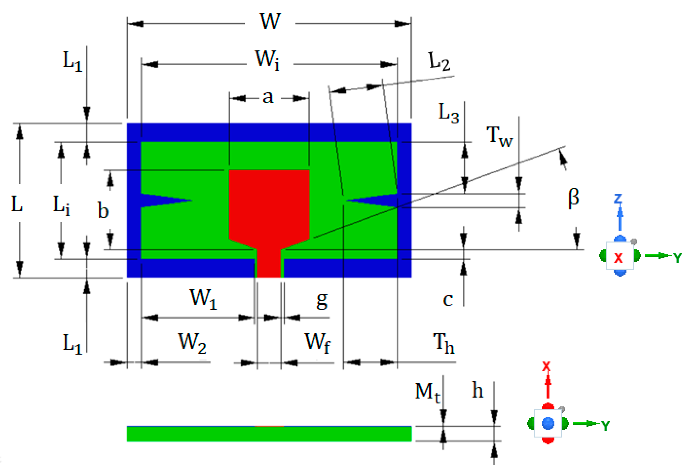
Figure 2.
The structure of the proposed antenna with geometrical parameters.
Figure 2.
The structure of the proposed antenna with geometrical parameters.
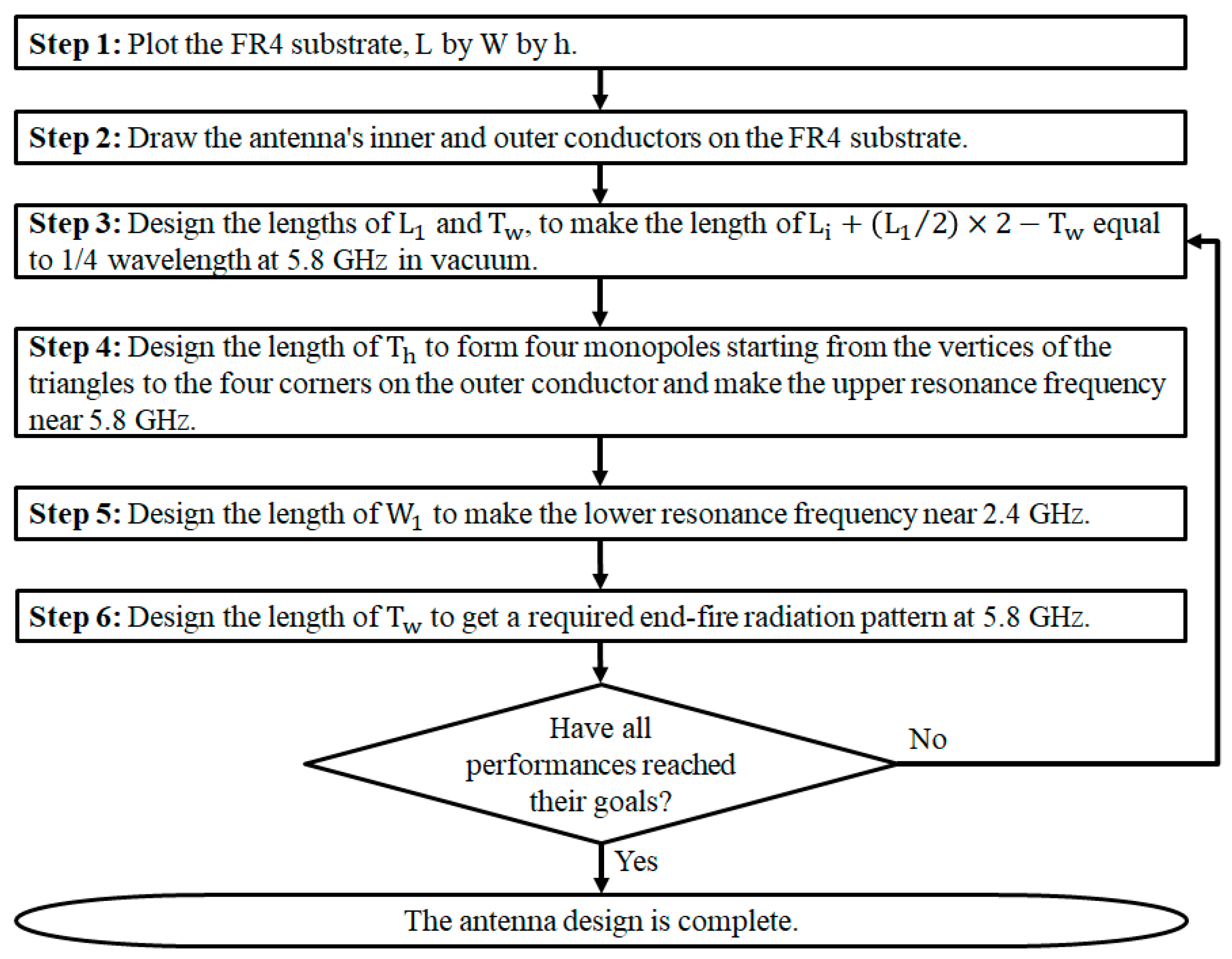
Figure 3.
The main design steps of the proposed antenna.
Figure 3.
The main design steps of the proposed antenna.
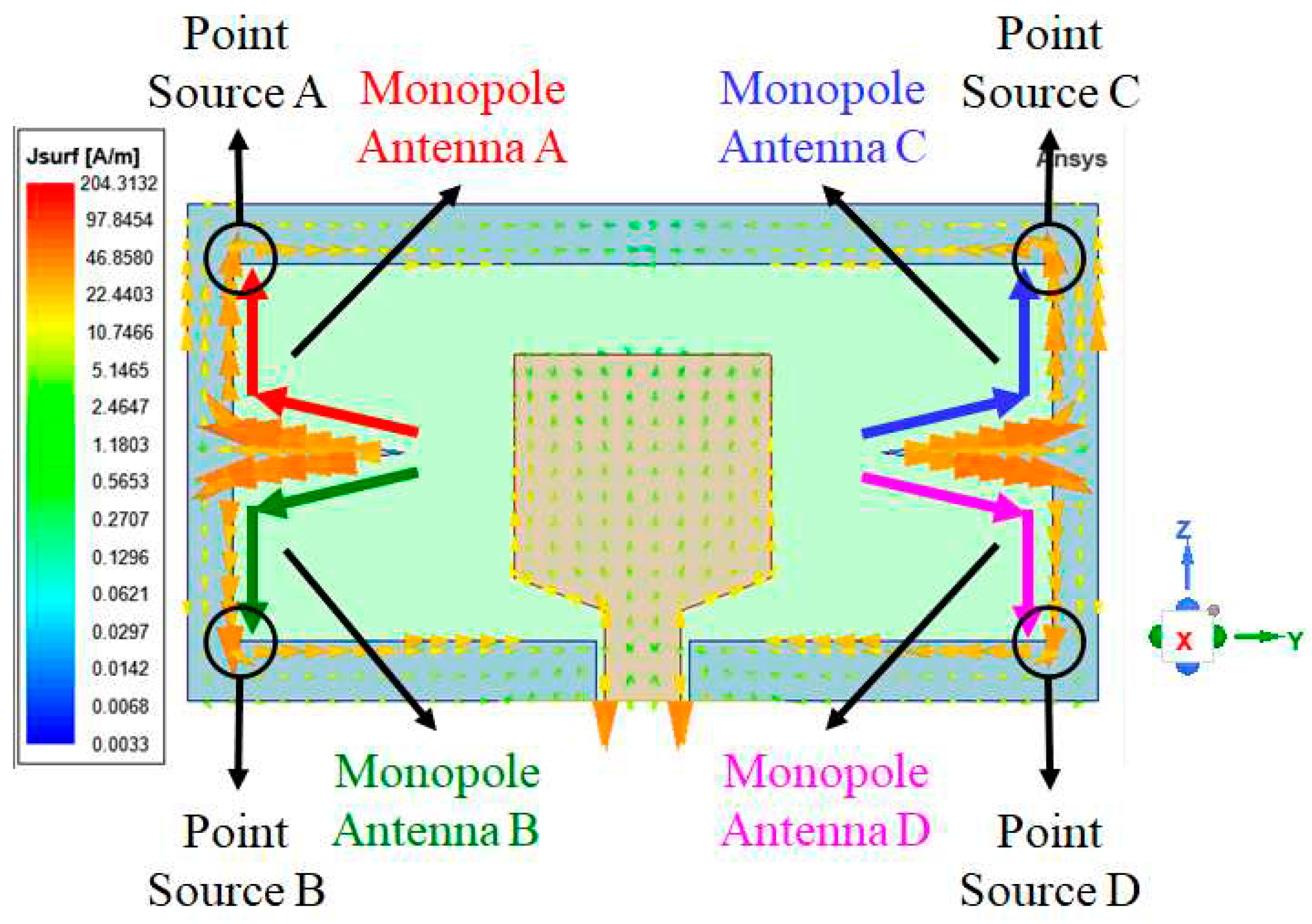
Figure 4.
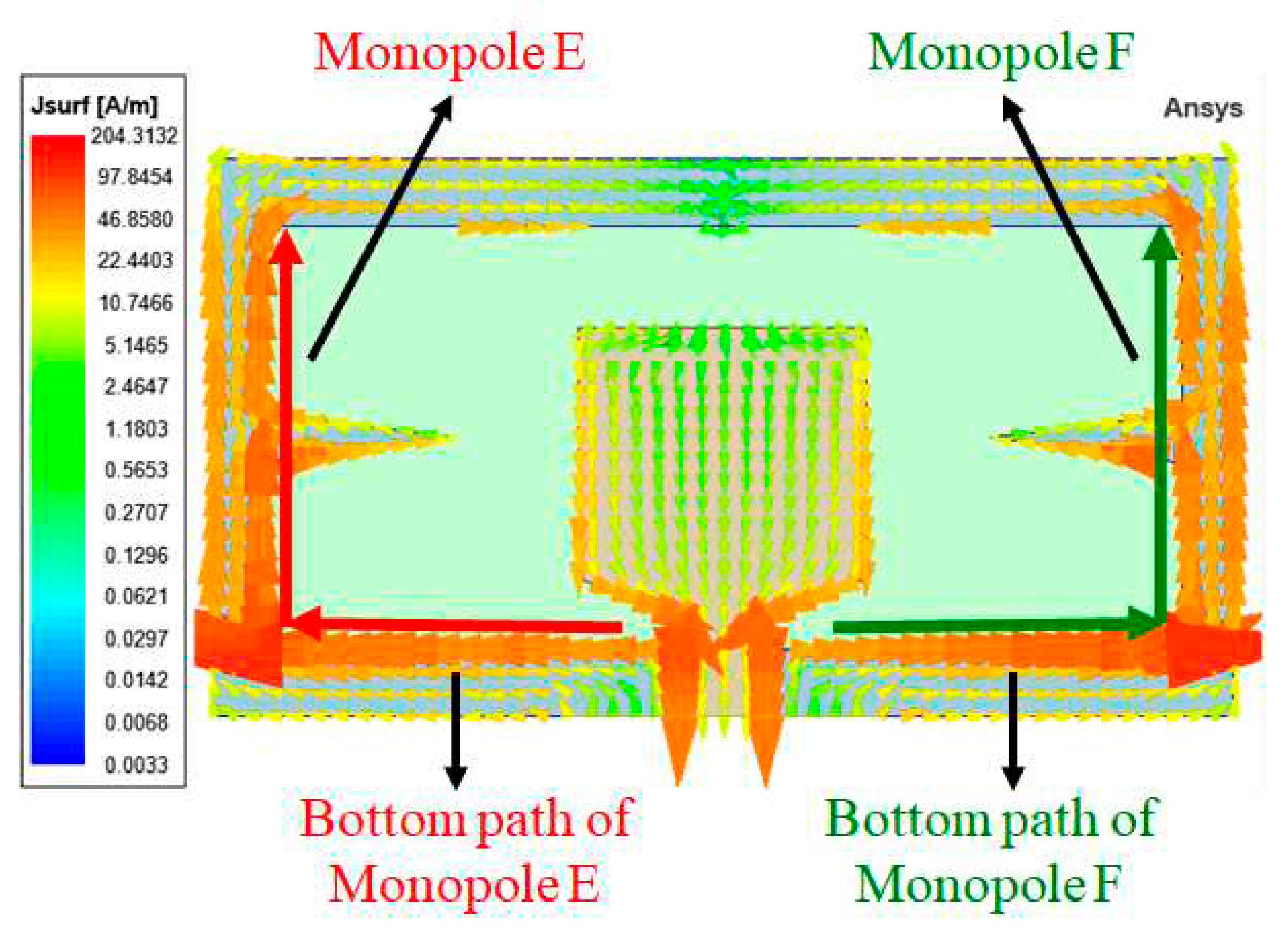
The simulated surface current density at 5.8 GHz.
Figure 4.
The simulated surface current density at 5.8 GHz.
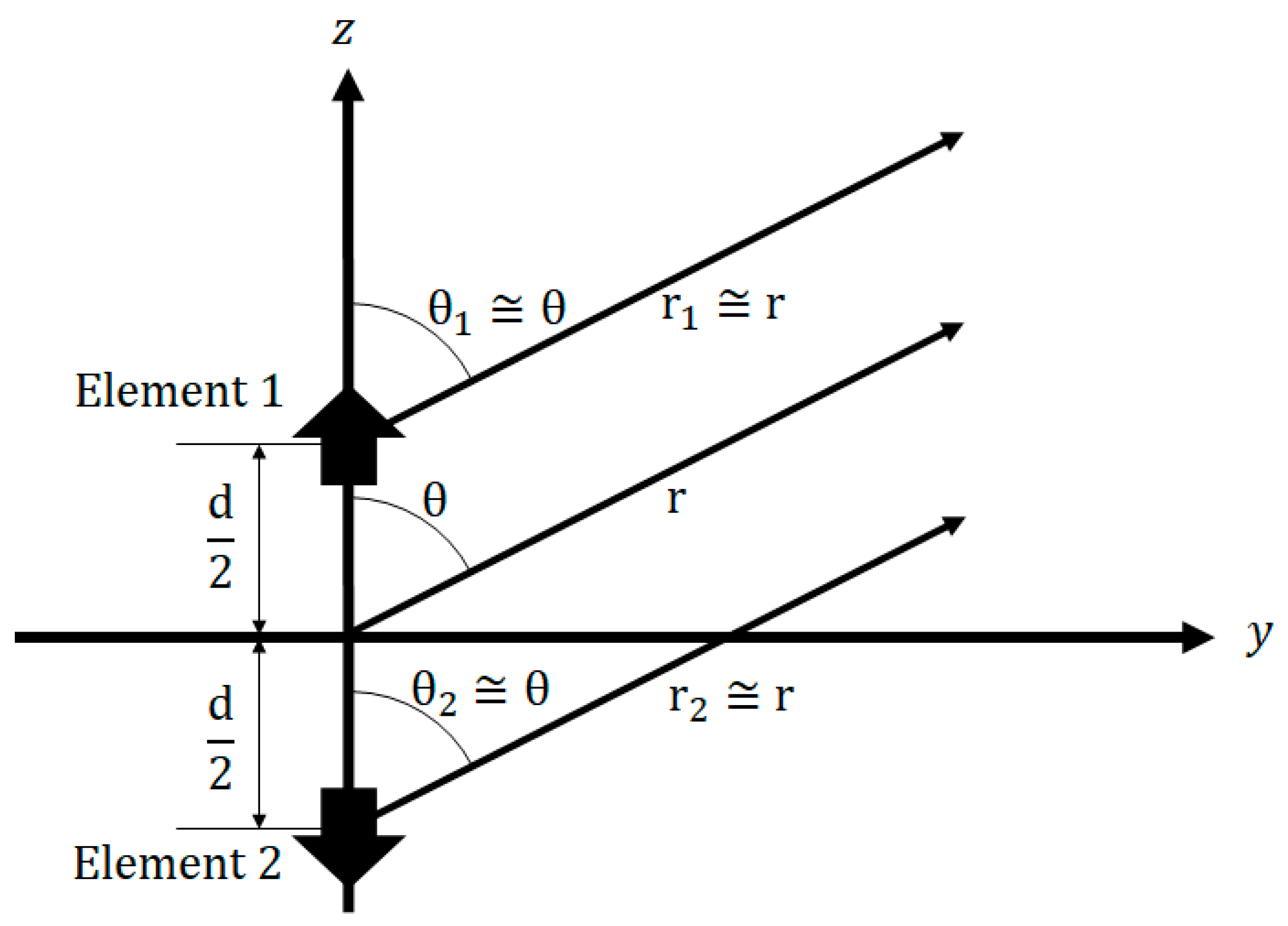
Figure 5.
Far-field observation of a two-element array consisting of two pointsources, Elements 1 and 2, positioned along the z-axis.
Figure 5.
Far-field observation of a two-element array consisting of two pointsources, Elements 1 and 2, positioned along the z-axis.
Figure 6.
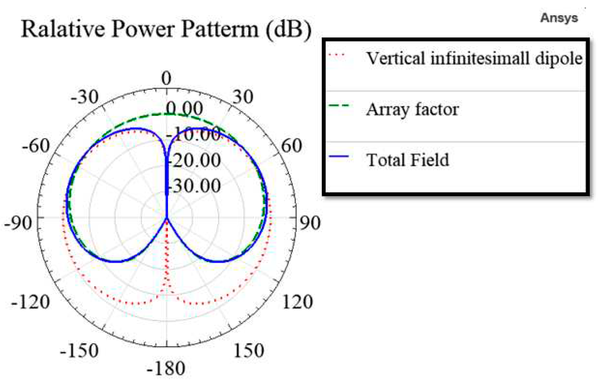
The relative power patterns of the vertical infinitesimal dipole, the array factor of Elements 1 and 2, and the total field of the two-element array antenna.
Figure 6.
The relative power patterns of the vertical infinitesimal dipole, the array factor of Elements 1 and 2, and the total field of the two-element array antenna.
Figure 7.
The simulated surface current density at 2.4 GHz.
Figure 7.
The simulated surface current density at 2.4 GHz.
Figure 8.
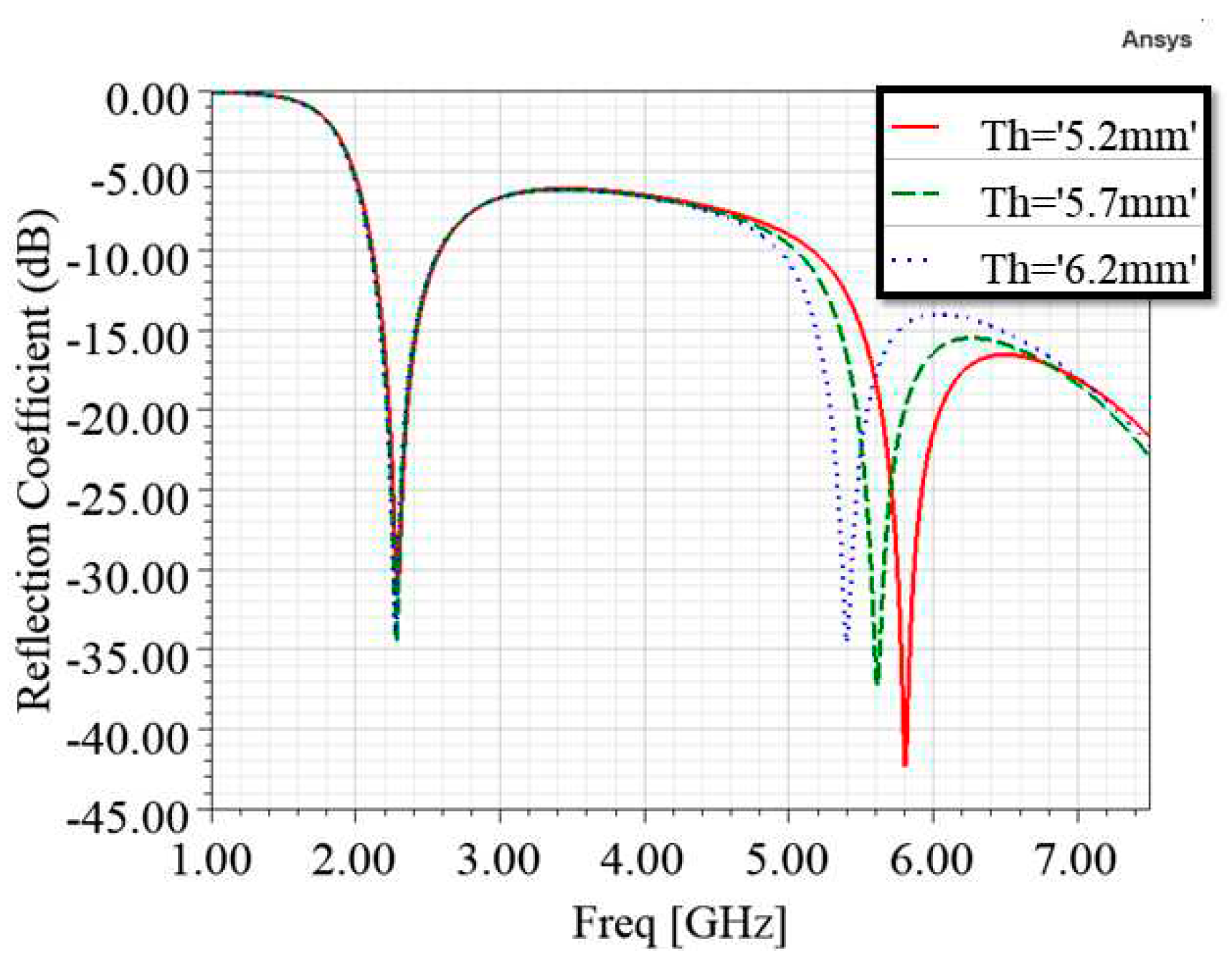
The simulated reflection coefficients for different values of .
Figure 8.
The simulated reflection coefficients for different values of .
Figure 9.
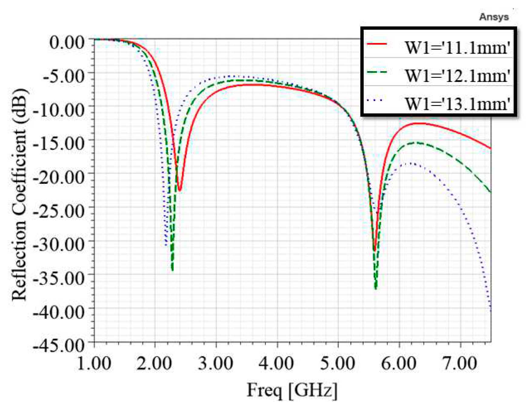
The simulated reflection coefficients for different values of .
Figure 9.
The simulated reflection coefficients for different values of .
Figure 10.
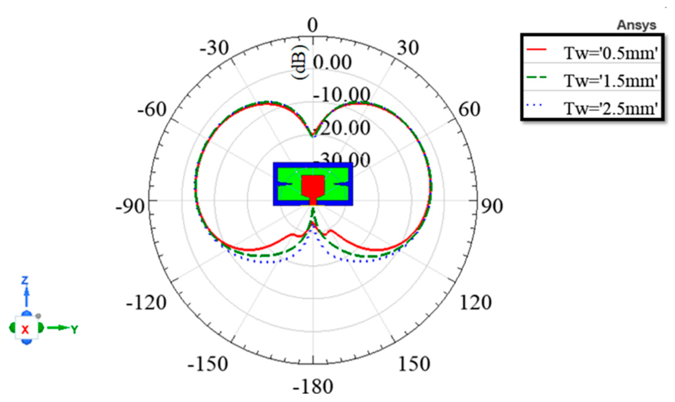
The simulated vertically polarized radiation patterns at 5.8 GHz in the y–z plane for different values of .
Figure 10.
The simulated vertically polarized radiation patterns at 5.8 GHz in the y–z plane for different values of .
Figure 11.
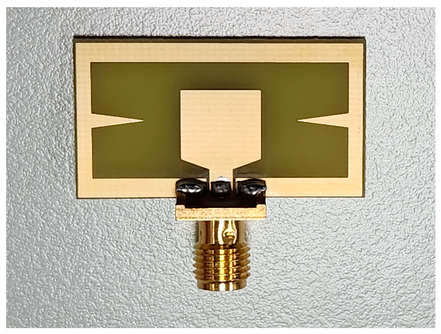
The prototype of the proposed antenna with an SMA connector soldered to it.
Figure 11.
The prototype of the proposed antenna with an SMA connector soldered to it.
Figure 12.
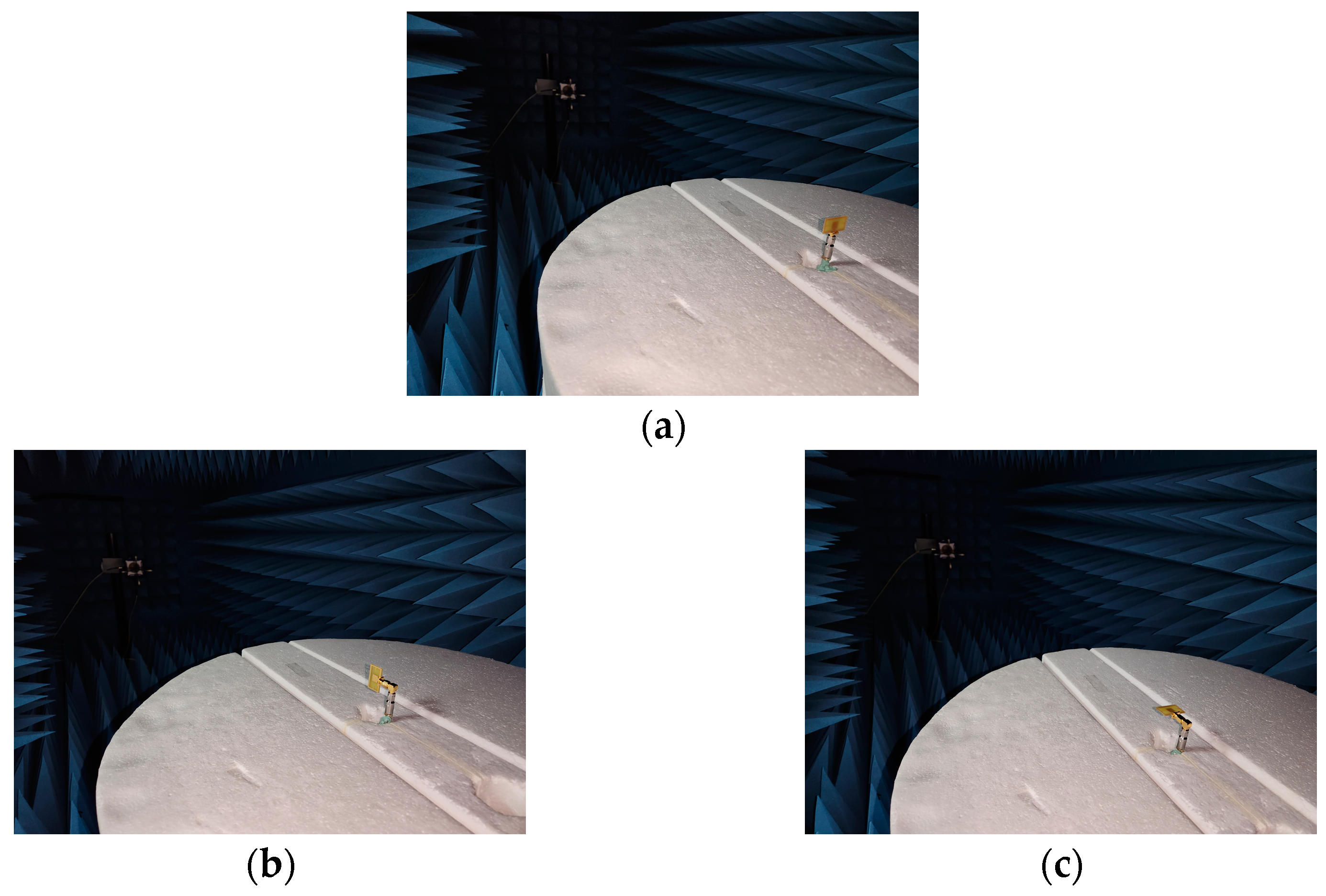
The measurement setup for radiation patterns. (a) x–y plane; (b) x–y plane; (c) x–y plane.
Figure 12.
The measurement setup for radiation patterns. (a) x–y plane; (b) x–y plane; (c) x–y plane.
Figure 13.
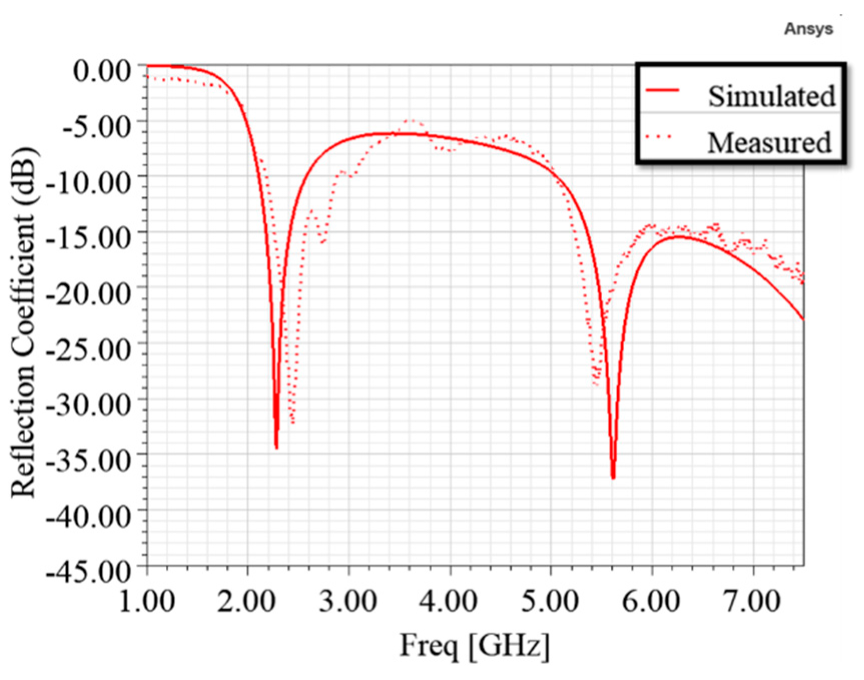
The comparison of the simulated and measured reflection coefficients of the proposed antenna.
Figure 13.
The comparison of the simulated and measured reflection coefficients of the proposed antenna.
Figure 14.
Comparison of the proposed antenna's simulated and measured radiation patterns in the x–y plane. (a) 2.4 GHz; (b) 5.8 GHz.
Figure 14.
Comparison of the proposed antenna's simulated and measured radiation patterns in the x–y plane. (a) 2.4 GHz; (b) 5.8 GHz.
Figure 15.
Comparison of the proposed antenna's simulated and measured radiation patterns in the x–z plane. (a) 2.4 GHz; (b) 5.8 GHz.
Figure 15.
Comparison of the proposed antenna's simulated and measured radiation patterns in the x–z plane. (a) 2.4 GHz; (b) 5.8 GHz.
Figure 16.
Comparison of the proposed antenna's simulated and measured radiation patterns in the y–z plane. (a) 2.4 GHz; (b) 5.8 GHz.
Figure 16.
Comparison of the proposed antenna's simulated and measured radiation patterns in the y–z plane. (a) 2.4 GHz; (b) 5.8 GHz.
Table 1.
The values of geometrical parameters for the proposed antenna.
Table 1.
The values of geometrical parameters for the proposed antenna.
| Parameter |
Dimension (mm) |
Ratio to the Wavelength of 2.4 GHz in Vacuum |
Ratio to the Wavelength of 5.8 GHz in Vacuum |
Angle (Degree) |
| W |
30.3 |
0.24 |
0.59 |
|
|
27.3 |
0.22 |
0.53 |
|
| L |
16.5 |
0.13 |
0.32 |
|
|
12.5 |
0.10 |
0.24 |
|
|
12.1 |
0.10 |
0.23 |
|
|
1.5 |
0.01 |
0.03 |
|
|
2 |
0.02 |
0.04 |
|
|
5.75 |
0.05 |
0.11 |
|
|
5.5 |
0.04 |
0.11 |
|
| a |
8.5 |
0.07 |
0.16 |
|
| b |
8.5 |
0.07 |
0.16 |
|
| c |
1 |
0.01 |
0.02 |
|
|
5.7 |
0.05 |
0.11 |
|
|
1.5 |
0.01 |
0.03 |
|
|
2.5 |
0.02 |
0.05 |
|
| g |
0.3 |
0.00 |
0.01 |
|
|
0.035 |
0.00 |
0.00 |
|
| h |
1.6 |
0.01 |
0.03 |
|
| Beta |
|
|
|
20 |
Table 2.
Characteristics of the simulated vertically polarized radiation patterns.
Table 2.
Characteristics of the simulated vertically polarized radiation patterns.
| Unit: Degree |
Y–z Plane |
x–z Plane |
| Left Plane |
Right Plane |
Left Plane |
Right Plane |
| 2.4 GHz |
Maximum gain angle |
−98 |
98 |
−95 |
91 |
Relative
−3 dB |
Beam angle |
−142 |
−49 |
48 |
142 |
−139 |
−49 |
46 |
134 |
| Beamwidth |
93 |
94 |
90 |
88 |
Relative
−10 dB |
Beam angle |
−165 |
−20 |
19 |
165 |
−165 |
−21 |
18 |
160 |
| Beamwidth |
145 |
146 |
144 |
142 |
| 5.8 GHz |
Maximum gain angle |
−61 |
62 |
−76 |
73 |
Relative
−3 dB |
Beam angle |
−102 |
−29 |
29 |
103 |
−118 |
−39 |
37 |
114 |
| Beamwidth |
72.96 |
74 |
79 |
77 |
Relative
−10 dB |
Beam angle |
−127 |
−11 |
11 |
129 |
−152 |
−16 |
14 |
148 |
| Beamwidth |
116 |
118 |
136 |
134 |
Table 3.
The comparison of the proposed antenna and published works on planar antennas.
Table 3.
The comparison of the proposed antenna and published works on planar antennas.
| Ref. |
Structure |
Operating Frequency |
Radiation Pattern |
Electrical Dimensions
(L × W × h) (λ0) |
| for Urban Areas |
for Open Areas |
| [11] |
Double-sided |
0.86 to 1.51 |
|
Yes |
0.3297 × 0.0344 × 0.0046 |
| [12] |
Double-sided |
3.9 to 5 |
|
Yes |
2.3400 × 0.1820 × 0.0260 |
| [13] |
Single-sided |
3.5/3.7/4.5/5/5.7 |
Yes |
Yes |
0.4690 × 0.1470 × 0.0092 |
| [14] |
Single-sided |
2.4 to 5.8 |
|
Yes |
0.1600 × 0.2000 × 0.0128 |
| This work |
Single-sided |
2.4/5.8 |
Yes |
Yes |
0.1320 × 0.2424 × 0.0128 |

