
Submitted:
25 May 2023
Posted:
26 May 2023
You are already at the latest version
Abstract
Novel TFN membranes were examined for the removal of heavy metals (Cu and Pb) from synthetic wastewater in forward osmosis (FO) experiments using MgCl2 as a draw solute. The TFN membranes were fabricated on top of a commercial PS35 ultrafiltration membrane by in-situ interfacial polymerization of piperazine (PIP) and 1,3,5-benzenetricarbonyl trichloride (TMC) containing different amounts of dispersed functionalized halloysite nanotubes (HNTs) nanoparticles. The HNTs nanoparticles were functionalized with the first generation of poly(amidoamine) (PAMAM) dendrimers. The TFN and the control TFC membranes showed rejections of Cu2+ and Pb2+, ranging from 94.5% to 98.1%. The presence of heavy metal in the feed solution enhanced the FO performance of all membranes. In particular, the reverse flux of MgCl2 decreased at least 2.5 times compared to the experiments with pure water as a feed. Simultaneously, the water flux also increased. The improved FO performance of the membranes in the presence of heavy metal ions is attributed to their adsorption by the membranes. The adsorption of heavy metals was confirmed by a decrease in the negativity of zeta potential and the results from inductively coupled plasma mass spectrometry (ICP-MS) of the membranes after the FO experiments.
Keywords:
forward osmosis
; heavy metal removal
; TFN membranes
; halloysite nanotubes
; first generation of poly(amidoamine) dendrimers
1. Introduction
With fast industrialization, the discharge of wastewater containing heavy metals into the environment is increasing [1]. Metals with an atomic mass between 63.5 and 200.6 and a specific gravity of more than five are classified as heavy metals [2]. Examples of heavy metals include zinc (Zn), copper (Cu), nickel (Ni) and lead (Pb). Heavy metals at low concentrations are vital for living organisms, including humans. However, at higher concentrations, they become toxic and harmful. For example, zinc is crucial for human health and vital for living tissue's physiological functions, but too much zinc can cause severe health problems, including skin irritation, vomiting, and nausea. Copper is essential for animal metabolism. However, copper's excessive ingestion can create toxicological problems such as cramps, vomiting, and even death. Nickel is known as a human carcinogen; it can also damage kidney and lungs. Because heavy metals are not biodegradable, they must be removed from wastewater [2,3].
Different methods to remove heavy metals from wastewater include chemical precipitation, adsorption, ion exchange, coagulation-flocculation, and membrane separation. The latter is environmentally friendly and offers high separation efficiency and energy savings [3]. Among different membrane separation processes, nanofiltration (NF) is most feasible for heavy metal removal from wastewater [4]. The NF is a pressure-driven membrane process in which separation relies on size exclusion and the Donnan potential [5]. The NF processes require the application of external pressure. The higher the pressure, the higher the energy consumption, which increases the process's operating cost. Furthermore, pressure-driven processes' membranes, including NF membranes, are susceptible to fouling, significantly reducing the membrane's lifespan [6].
The NF membranes can be used in forward osmosis (FO) processes [7]. FO is an emerging membrane technology with potential applications in desalination, wastewater treatment and reclamation, bioproducts and food industry, energy generation and resource recovery [8,9]. FO utilizes the osmotic pressure difference of solutions across a semipermeable membrane to draw water from a dilute feed solution (FS) to a more concentrated draw solution (DS); the salt moves in the opposite direction. Without external pressure, the fouling tendency of FO membranes is significantly reduced [10,11]. However, the FO is generally not a standalone process; it must be combined with another process. An example of a hybrid FO-NF process for heavy metal removal is shown in Figure 1. Heavy metals are rejected in the FO process. At the same time, water permeates from the feed to the draw solution. Therefore, the permeating water in the FO process is not the final product as it dilutes the draw solution. The purpose of the second stage, an NF process, is to regenerate the draw solution while producing pure water. The advantage of a hybrid process arises from using a "clean" draw solution rather than direct "dirty" wastewater in the NF process, which minimizes membrane fouling.
The membranes for the FO and NF steps in Figure 1 could be the same. If the NF-stage membrane effectively rejects the draw solute, it will also prevent reverse draw solute transport in the FO-stage. Therefore, the membranes for the first stage in Figure 1 are often referred to as "NF-like FO" membranes [7]. The hybrid process in Figure 1 can also be used for water desalination. However, since monovalent salts (e.g. NaCl) are to be rejected in the FO stage, the process would require an RO membrane or "RO-like FO" membrane [12]. Heavy metals occur as multivalent salts; it is thus sufficient to use NF-like FO membranes for heavy metal removal from wastewater. Moreover, NF-like FO membranes could achieve higher water flux than RO-like FO membranes due to a looser selective layer [13].
There is an increasing number of examples of NF-like FO applications. Abdullah et al. used commercial NF membranes in PRO and FO processes for treating aerobically treated palm oil mill effluent (AT-POME). They reported that the colour (i.e., impurity) of AT-POME could be removed entirely using magnesium chloride (MgCl2) as a draw solution [14]. The same research group also used four commercial NF membranes in the FO and PRO processes for copper ion removal from wastewater. They reported near-complete removal of copper removal regardless of the membrane type and membrane orientation associated with low reverse draw-solute flux [7]. Setiawan et al. tested different types of in-house-made NF hollow fibre membranes in the FO process with pure water as a feed and 0.5 mol L-1 MgCl2 as a draw solution. They reported a water flux as high as 9.74 L. m-2.h-1 [15]. Su et al. developed cellulose acetate-based NF membranes and studied the effect of draw solution concentration and membrane orientation (PRO vs FO) on the water flux. Using 0.5 – 2.0 mol L-1 of MgCl2 as a draw solution, they reported a higher water flux in the PRO mode (2.7 – 7.3 L. m-2 h-1) than in the FO mode (1.8 -5.0 L.m-2 h-1) [16].
Recently, we reported the properties of novel TFN-NF membranes with different loadings of modified halloysite nanotubes (HNTs) loadings. HNTs were functionalized with the first generation of poly(amidoamine) (PAMAM) dendrimers, and the resulting nanoparticles, HNTs-G1, were dispersed in the TMC monomer solution before interfacial polymerization [17]. Although the positively-charged nanoparticles did not switch the negative surface charge of the resulting TFN membranes, their presence led to a remarkable increase in the rejection of MgCl2 without sacrificing the rejection of Na2SO4 [17]. As such, we have proven that MgCl2, commonly used as a draw solute because of its high osmotic pressure, can be effectively recovered by our novel TFN-NF membranes. In this manuscript, we explore the applicability of these membranes for removing heavy metal ions (Cu2+ and Pb2+) from synthetic aqueous solutions in the FO process. We investigate the role of the heavy metal ions in the feed solution on our novel TFN membranes' water flux and reverse solute flux. We also compare the rejection of Cu2+ in the FO and NF using the same membrane.
2. Materials and Methods
2.1. Materials
The synthesis procedure of the first-generation PAMAM dendrimers and the subsequent functionalization of HNTs to produce the final nanoparticles, HNTs-G1 used to fabricate TFN membranes was described elsewhere [18]. TFN membranes were prepared using four different loadings of HNTs-G1, 0, 0.025, 0.05 and 0.1%, where 0% loading corresponds to the control TFC membranes. The TFN membranes are coded as TFN(x%), where x corresponds to the loading of HNTs-G1. The nanoparticles were dispersed in the solution of 1,3,5-benzenetricarbonyl trichloride (TMC) in n-hexane before the interfacial polymerization with the aqueous solution of piperazine (PIP). Commercial PS35 ultrafiltration (UF) membrane was used as a substrate for the interfacial polymerization of two monomer solutions. The details of the synthesis protocol of TFN membranes are described elsewhere [17].
Laboratory-grade Copper (ΙΙ) sulphate pentahydrate (CuSO4⋅5H2O) and lead (ΙΙ) nitrate (Pb(NO3)2) for the synthetic feed solutions, and magnesium chloride (MgCl2) for the draw solution were and purchased from Sigma-Aldrich, Saint Louis MO. Deionized (DI) water was used to prepare the feed and draw solutions.
2.2. Nanoparticle and Membrane Characterization
Functionalized and pristine HNTs, and fresh TFN and TFC membranes have been thoroughly characterized using scanning electron microscopy (SEM) and attenuated total reflection-Fourier transform infrared (ATR-FTIR) spectroscopy. In addition, the contact angle and zeta potential of the surface of the membranes were determined. The results of these characterizations are described elsewhere [17] and will be briefly summarized in the next section.
The zeta potential of the surface of membranes was measured by a zeta analyzer (Zetasizer PSS0012-22, Malvern Instruments) before and after the tests with heavy metals. The adsorption of heavy metals on the membrane surface was evaluated indirectly based on the heavy metal concentrations in the feed and draw solutions measured using Agilent 7900 inductively coupled plasma mass spectrometer (ICP-MS Aligent, Santa Clara, CA).
2.3. Forward Osmosis Tests and Data Analysis
The performance of TFN and the control TFC membranes was evaluated in our novel crossflow FO testing system, which was described in detail elsewhere [19]. The new feature of the FO system is bypass lines that allow the isolation of the membrane cell from the rest of the system. In turn, it allows a sudden replacement of DI water at both sides of the membrane with a desired feed and/or draw solution, which initiates the actual FO experiment [20]. During each experiment, the mass of the tanks containing the feed and draw solution is monitored in real-time using high-resolution (0.01 g) balances (6202-1S, Entris Precision, Sartorius, Germany). Also, the conductivity and temperature in the feed tank solution are monitored continuously using a benchtop conductivity/temperature meter (CON2700, Oakton Instruments, Woonsocket, RI, USA). The membranes were tested in the orientation of the active layer facing feed solution (AL-FS). We used the same draw solution in all experiments, i.e. 1 M MgCl2 aqueous solution. For the feed solution, we used either DI water or 200 ppm solutions of CuSO4⋅5H2O or Pb(NO3)2). The corresponding theoretical concentrations of Cu2+ and Pb2+ were 50.9 ppm and 125.1 ppm, respectively. However, the actual initial concentrations of MgCl2, Cu2+ and Pb2+ were slightly lower than the above values because of a dilution of the feed and draw solutions with the residual DI water in the membrane cell and the pumps circulating the feed and draw solution [20].
The water flux (Jw) and the reverse draw solute flux (Js) were evaluated from the respective steady-state mass transfer rates of water (dmw/dt) and the draw solute (dms/dt):
where, ρ is the density of water, and A is the membrane area. In the experiments with feed solution containing heavy metals, the solute and water permeate in the same direction. Therefore, the heavy metal rejection (R) is:
where, Cp and Cf are steady-state concentrations of heavy metal in permeate and feed, respectively. It is essential to remember that during experiments, both feed and draw solutions were circulated at the respective sides of the membrane while the water permeated from the feed to the draw side. Therefore, in principle, no steady state could be attained. However, since the volume of water permeated across the membrane was negligible compared to the volumes of feed and draw solutions, a pseudo-steady state could be reached, which we will refer to as a steady state. The following section will show that the steady-state existed almost instantaneously after the experiment's initiation. Since the initial concentration of heavy metal in the draw solution was zero, the Cp was evaluated from:
where: Cd,f, which is the concentration of heavy metal in the draw solution at the end of the experiment, and ΔVd, which is the total volume of water permeated from the feed to the draw solution, were measured directly. The final volume of the draw solution at the end of the experiment (Vd,f) was estimated from:
where: Vd,i is the initial volume of the draw solution, which in every experiment was 840 mL, and Vr,d is the residual volume of water in the draw-side of the system, which represents the volume of water in the tubing, the membrane cell and the pump. The final volume of the feed solution (Vf,f) was estimated from a similar equation:
where: Vf,i is the initial volume of the feed solution, which in every experiment was 500 mL, and Vr,f is the residual volume of water in the feed side of the system. The residual volumes of water at the draw and feed sides were Vr,d = 161.5 mL and Vr,f = 155.5 mL [19].
2.4. Rejection of heavy metals in NF process
In addition to FO, the rejection of Cu2+ (200 ppm CuSO4.5H2O solution) was also measured in NF experiments. The tests were performed using the TFN and the control TFC membranes in a continuous crossflow filtration system [21]. The experiments were carried out at 24 ± 2 °C and 10 ±1 bar. Heavy metal rejection was evaluated using Eq. (3). Unlike FO tests, Cp and Cf were measured directly from the samples taken when steady-state permeation was established. The feed and permeate samples were analyzed using ICP-MS. Due to a large feed solution volume (~20 L), a decrease in Cf because of the adsorption of Cu2+ by the membranes was not observed.
3. Results and Discussion
3.1. Nanoparticle and Membrane Characterization
The following summarizes the important properties of nanoparticles and the resulting TFN and TFC membranes described in detail previously [17]. These excerpts will help better understand this work's core results, i.e., the FO performance and how heavy metals influence this performance.
The successful functionalization of HNTs using the first-generation PAMAM dendrimers was confirmed by two additional characteristic peaks in the ATR-FTIR spectrum of the functionalized HNTs. Based on the TGA analysis, the organic content resulting from the functionalization was approximately 5%. The TEM and SEM images revealed that nanoparticles are heterogeneous in size but have a characteristic tubular geometry. The variation in size could not be attributed to the functionalization of HNTs. On the other hand, the incorporation of the first-generation PAMAM dendrimers greatly affected the zeta potential of the nanoparticles. The zeta potential increased from -34.5 mV to 2.2 mV for the functionalized HNTs, because of the presence of amino groups from the first generation of PAMAM dendrimers [17].
The formation of the active polyamide (PA) layer and incorporation of the nanoparticles into the PA layer were confirmed by the ATR-FTIR spectra. The relative intensity of the characteristic primary amide and aromatic amide peaks was greater in TFN than in the control TFC membrane. However, the was no clear trend between the peak intensity and the nanoparticle loading for the TFN membranes. The SEM images of the top surface of the membranes revealed a typical nodular structure. Incorporating the nanoparticles decreased the uniformity of the top surface because of the penetration of the nanoparticles and possible aggregation of HNTs at higher loadings. The water contact angle of TFN membranes was lower than that of control TFC membranes, and the increase in hydrophilicity was attributed to the hydroxyl and amine groups of the nanoparticles. However, the water contact angle did not continue to decrease with the nanoparticle loading. At the highest loading, the contact angle increased, likely because of the aggregation of some nanoparticles. Although the zeta potential of the HNTs functionalized with first-generation PAMAM dendrimers was slightly positive, their incorporation into the PA layer had little effect on the zeta potential of the resulting TFN membranes compared to the control TFC membrane [17].
3.2. FO Performance
The FO performance of the membranes strongly depends on a draw solute. The latter should generate high osmotic pressure while the permeation of salt across the membrane is minimized. In this study, we selected MgCl2 as a draw solute because, as we have shown previously, our novel TFN-NF membranes have excellent rejection of MgCl2 [17].
Figure 2 shows the progress of the dynamic FO experiments with the control TFC membrane using DI water and a 200 ppm CuSO4⋅5H2O as a feed solution. In both cases, 1 M aqueous solution of MgCl2 was used as a draw solution. The processing of the raw experimental data is described elsewhere [19]. In both experiments, the rate of water mass change (dmw/dt) is linear, indicating steady-state conditions right after the initiation of the experiment. It is important to note that the rate of the mass increase at the draw side is equal to the rate of the mass decrease at the feed side, as it should be. It is because the FO system is closed, and the total mass of water is constant. The water transport from the feed to the draw side decreases the concentration of the draw solute, and thus, the driving force for the water transport decreases during the experiment. However, because the total mass of water transferred over an hour-long experiment (< 10 g) was much smaller than the total mass of either feed (~400 g) or draw solution (~840 g), the osmotic pressure gradient remained constant.
The most remarkable observation from Figure 2 is that the slope of the rate of mass change, i.e. Jw, is 50% greater in the experiment with the feed solution containing 200 ppm Pb(NO3)2 than in the one with DI water as a feed solution. In principle, heavy metal salt in the feed solution decreases the osmotic pressure difference across the membrane. As a result, one could expect the water flux in the experiment with pure water to be higher than in the experiment with a heavy metal salt solution in the feed.
Figure 3 presents the progress of the same dynamic FO experiments with the TFC membrane focusing on the reverse salt flux of the draw solute (MgCl2) as a function of time. Unlike the water flux, it takes several minutes for MgCl2 transport to become constant, particularly in the experiment with DI water as a feed. The most remarkable result in Figure 3 is markedly smaller Js of MgCl2 in the experiment with the feed solution containing the heavy metal salt. Heavy metal ions in the feed solution appear to suppress the reverse of MgCl2, which is desirable.
When analyzing, the experiment results with the feed containing 200 ppm CuSO4⋅5H2O, we assumed that the membrane completely rejects the heavy metal salt. In other words, the feed solution's conductivity changes are solely determined by the transport of MgCl2 from the draw to the feed solution. One of the concerns with using MgCl2 as a draw solute was its incomplete rejection by our membranes in the NF experiments [17]. However, heavy metal salt in the feed solution significantly alleviates this problem.
The FO tests similar to those summarized in Figure 2 and Figure 3 were also performed with TFN membranes, and the results for the water flux (Jw) and reverse solute flux (Js) are shown in Figure 4 and Figure 5, respectively. For each loading of nanoparticles, including zero loading, i.e., TFC membranes, we prepared two membrane sheets, and we cut four coupons from each sheet. Therefore, in total, we fabricated 32 coupons for the FO tests. The bars representing Jw and Js in the experiments with DI water as a feed solution are the average from tests using four coupons of the same membrane type. For the experiments with the feed solution containing Pb(NO3)2 or CuSO4⋅5H2O the bars are the average from tests using two coupons of the same type of membrane.
Figure 4 confirms that heavy metal salt in the feed solution enhances the water flux. For TFC membranes, the water flux increases in the following: DI water < Pb(NO3)2 solution < CuSO4.5H2O solution. For TFN membranes, the water flux for the Pb(NO3)2 solution is higher than for the CuSO4.5H2O solution. However, the positive effect of the heavy metal in the feed on the water flux is undeniable. The water fluxes of less than 4 L⋅m-2.hr-1 are relatively low for the FO process. Nonwoven support, a part of commercial PS35 membranes on which TFC and TFN membranes were synthesized, is responsible for internal concentration polarization (ICP). The latter significantly reduces the effective osmotic pressure gradient, the driving force for water transport in FO processes [7]. There is no clear trend between the water flux and the loading of HNT-G1.
As shown in Figure 5, the effect of heavy metal cations in the feed solution on the reverse flux of MgCl2 is even stronger than that on the water flux. The reduction in the reverse salt flux in the presence of heavy metal ions is at least 50%, but it can also be significantly greater. For example, for TFN(0.1%), Js in the presence of Pb(NO3)2 solution is 1/6 of that with DI water as a feed. For both TFC and TFN membranes, the reverse MgCl2 flux decreases in the following order DI water > CuSO4⋅5H2O solution > Pb(NO3)2 solution. Although the respective feed solutions concentrations containing heavy metal salts were the same (200 ppm), the theoretical concentration of Pb2+ was greater than that of Cu2+ (125.1 ppm vs 50.9 ppm). The greater concentration of Pb2+ in the feed solution could be responsible for the more significant reduction in Js in the presence of Pb(NO3)2 in the feed solution. Considering the effect of loading of HNTs-G1 and the reverse salt flux, Js decreases with the loading of HNTs-G1 when the feed solution is DI water and the aqueous solution of CuSO4⋅5H2O. On the other hand, the is no clear trend between the loading and Js when the feed solution contains the aqueous solution of Pb(NO3)2. It is also important to note that the reverse salt flux of TFC membrane is comparable to that of TFN(0.025%) membrane.
The surface of fresh TFC and TFN membranes was negatively charged [17], which can be attributed to carboxylic acid groups from the unreacted acyl chloride of the TMC monomer [22]. Consequently, they can adsorb positively charged ions such as Pb2+ and Cu2+ [23]. According to Hurwitz et al. [24], adsorbed heavy metal ions on a solid surface can produce a strong hydration force, increasing the hydrophilicity. It is well known that the water flux increases as the surface hydrophilicity of membranes increases. In addition, adsorbed Cu2+ or Pb2+ would facilitate the rejection of Mg2+ cations based on charge repulsion. To maintain the electroneutrality, Cl- anions would remain at the draw side of the membrane [25].
To confirm the adsorption of heavy metal ions on the membrane surface, we performed the ICP-MS analysis of the selected membranes (TFC and TFN(0.025%)) from the experiments with the feed solution containing CuSO4⋅5H2O. For comparison, we also did the ICP analysis of the same types of membranes from the experiments with DI water as a feed solution. In addition, we also measured the zeta potential of these membranes before and after the FO experiments. Table 1 summarizes the ICP and zeta potential analysis results.
As expected, copper was detected on both TFC and TFN(0.025%) membranes after the tests with a feed solution containing CuSO4⋅5H2O. Interestingly, copper was also detected on these membranes after the tests with DI water as a feed solution, particularly on the TFN(0.025%) membrane. The latter was likely because of residual heavy metal salts accumulated in the system, particularly in the membrane cell. On the other hand, more copper was detected after the tests with the feed solution containing CuSO4⋅5H2O than after the tests with DI. Because of possible contamination from the previous tests, the mass of copper reported in Table 1 should not be considered quantitatively. Nevertheless, the ICP analysis provides strong evidence for the adsorption of heavy metals on our TFC and TFN membranes. The adsorption of Cu2+ (and also Pb2+) by membranes can be attributed to amine groups' chelation reaction with heavy metal cations [26].
Further confirmation for the membrane adsorption of heavy metal ions comes from analyzing the zeta potential results. As shown in Table 1, the zeta potential of the new TFC membrane was -17.8 mV. After the test with DI water as a feed solution, the zeta potential decreased to -10.2 mV; however, after the test with the 200 ppm CuSO4⋅5H2O solution as a feed, the zeta potential increased more, to -8.72 mV. The same trend was observed for the TFN(0.025%) membrane. A zeta potential increase is attributed to the adsorption of metal cations. The zeta potential increase after the tests with DI water was likely because of Mg2+ adsorption from the draw solution.
3.3. Rejection of Heavy Metals in FO and NF Processes
The presence of heavy metal cations in feed solution improves the FO performance of TFC and TFN membranes. However, the membrane's primary role in the FO process is to reject heavy metals while allowing water to permeate from the feed to the draw solution. The rejection of Cu2+ and Pb2+ was calculated using Eq. (3), in which Cp was evaluated using Eq. (4). The latter equation assumes that the initial concentration of Cu2+ and Pb2+ in the draw solution was zero, which was the case, and the existence of steady-state permeation during the entire FO experiment. The linear rate of mass change of water (Figure 2) and practically linear rate of mass change of heavy metal cations in the draw solution (Figure 3) confirmed the existence of steady-state conditions throughout the experiments.
To calculate R we used Cf measured after the experiment, which ranged from 34 to 36 ppm for Cu2+ and 77 to 92 ppm for Pb2+. These values are lower than the respective theoretical concentrations of Cu2+ and Pb2+ that consider the dilution factor (0.5/0.656), i.e. 39 ppm and 95 ppm. The corresponding Cp values for Cu2+ ranged from 0.5 to 1.5 ppm and from 2 and 5 ppm for Pb2+. The higher concentration of Pb2+ than Cu2+ was because of the higher Cf of the former. Using Cf measured after the experiment to calculate ion rejection leads to a conservative estimation of R values.
Figure 6 summarizes the average rejections of Cu2+ and Pb2+ by TFC and TFN membranes in FO tests. Each value in Figure 6 represents the average from two independent experiments. It can be noticed that the average rejection of Pb2+ by TFC membrane (97.4%) is higher than Cu2+ (96%). On the other hand, for TFN membranes, the situation is the opposite; the average rejection of Cu2+ by TFN membranes (97.2- 98.1%) is higher than Pb2+ (94.5 – 96%). As a result, the rejection of Pb2+ by TFC membranes is higher than by TFN membranes. The presence of HNTs-G1 slightly increases the rejection of Cu2+ of the resulting TFN, but the opposite is true for Pb2+. However, there is no apparent trend between the loading of HNTs-G1 and heavy metal rejection by the membranes. Although differences in heavy metal rejections in Figure 6 might not be statistically significant, they are high, above 94%.
As shown in Table 1, high rejections of Cu2+ and Pb2+ might be partly due to the adsorption of heavy metal ions by the negatively charged surface of TCF and TFN membranes. In principle, the adsorption of heavy metals by the membranes (mads) could be evaluated from the mass balance using the following equation:
All parameters on the right-hand side of Eq. (7) were measured or evaluated in each experiment. However, the calculated mads were 2-3 orders of magnitude greater than the values reported in Table 1. The main reason for this discrepancy was the assumption that the membranes only adsorbed heavy metal ions. However, they could also be adsorbed in tubes and the membrane cell. In other words, there would be another negative term on the right-hand side of Eq. (7). The hypothesis of possible adsorption of heavy metal ions not only by the membranes was confirmed by the presence of Cu2+ on the membranes even in the experiments in which the feed solution was DI water (Table 1). However, it is essential to emphasize that the possible adsorption of heavy metal ions in the system and their incomplete removal between the experimental runs do not affect the calculation of R values.
In addition to rejecting heavy metals in FO experiments, we tested 6 TFC and 6 TFN(0.05%) membranes in NF experiments with a 200 ppm CuSO4.5H2O feed solution at 10 bar. The average rejection of Cu2+ by the TFC membranes was 96.25%, comparable to the corresponding value in the FO tests. On the other hand, the average rejection of Cu2+ by the TFN(0.05) membranes was only 92.89%, considerably lower than 98% by the same membranes in the FO tests. A lower rejection of heavy metals in NF compared to FO could be expected. In both processes, the transport of heavy metals is driven by the concentration gradient across the membrane. In addition, heavy metals might also be dragged along the permeating water in the NF process driven by the hydraulic pressure gradient across the membrane.
The FO performance, including heavy metal ion rejection of TFC and TFN membranes, is generally comparable. This suggests a minor role of HNTs-G1, further substantiated by a general lack of trend between the nanoparticle loading and the membrane performance. A significant reduction in the reverse salt flux and the simultaneous increase in the water flux in the presence of heavy metal ions in the feed solution, attributed to their adsorption, is likely due to the negative surface charge of both TFC and TFN membranes. Two approaches are possible to increase the adsorption of heavy metals by the membranes and improve further their FO performance and heavy metal rejection. One way is to use nanoparticles that would increase the negative surface charge of the final TFN membranes, for example, carboxyl group-grafted molybdenum disulfide [27] or silver-functionalized biomimetic nanoparticles [28]. Another approach would be to select nanoparticles that specifically interact with heavy metal ions. The thiol (SH) functional groups enhance heavy metal adsorption through complexation [29]. They can be introduced into TFN membranes via, for example, L-cysteine functionalized cellulose nanocrystals [30]. Despite an increase in the FO water flux in the presence of heavy metal ions, the reported Js in Figure 4 remain small because of internal concentration polarization. The latter arises from the nonwoven support of the commercial PS35 membranes used to fabricate the TFC and TFN membranes. Increasing Jw to an attractive level for a practical FO application would require optimizing the porous support of the TFC and TFN membranes [31].
4. Conclusions
We have successfully fabricated thin-film nanocomposite (TFN) membranes through in-situ interfacial polymerization of piperazine (PIP) and 1,3,5-benzenetricarbonyl trichloride (TMC) containing different amounts of functionalized halloysite nanotubes (HNTs) nanoparticles. The HNTs nanoparticles were functionalized with the first generation of poly(amidoamine) (PAMAM) dendrimers. These membranes demonstrated excellent rejection of heavy metal ions, specifically Cu2+ and Pb2+, ranging from 94.5% to 98.1%. Interestingly, the TFN membranes exhibited higher rejection of Cu2+ compared to Pb2+, while the opposite trend was observed for the control TFC membranes. In addition, the presence of heavy metals in the feed solution improved the performance of all membranes in the forward osmosis (FO) process, resulting in at least a 2.5-fold decrease in the reverse flux of draw solute (MgCl2) and an increase in water flux. This improved performance is attributed to the adsorption of heavy metals by the membranes, as confirmed by the decrease in the negativity of zeta potential and the results from inductively coupled plasma mass spectrometry (ICP-MS) analysis of the membranes. The latter provided direct evidence of heavy metal adsorption by the membranes. The performance of TFN and TFC membranes, including heavy metal ion rejection, was similar, indicating a minor role of HNTs-G1 nanoparticles. Therefore, to further improve the FO performance and heavy metal rejection, it is recommended to use nanoparticles that would increase the negative surface charge of the resulting TFN membranes or could specifically adsorb heavy metal ions.
Acknowledgments
The authors gratefully acknowledge the financial support provided by the Natural Science and Engineering Research Council (NSERC) Canada, Discovery Grant (DG), Grant number: 04443.
References
- Cheng, X.; Zhang, Y.; Shao, S.; Lai, C.; Wu, D.; Xu, J.; Luo, X.; Xu, D.; Liang, H.; Zhu, X. Highly Permeable Positively Charged Nanofiltration Membranes with Multilayer Structures for Multiple Heavy Metal Removals. Desalination 2023, 548, 116266. [Google Scholar] [CrossRef]
- Fu, F.; Wang, Q. Removal of Heavy Metal Ions from Wastewaters: A Review. J. Environ. Manage. 2011, 92, 407–418. [Google Scholar] [CrossRef] [PubMed]
- Abdullah, N.; Yusof, N.; Lau, W.J.; Jaafar, J.; Ismail, A.F. Recent Trends of Heavy Metal Removal from Water/Wastewater by Membrane Technologies. J. Ind. Eng. Chem. 2019, 76, 17–38. [Google Scholar] [CrossRef]
- Samavati, Z.; Samavati, A.; Goh, P.S.; Fauzi Ismail, A.; Sohaimi Abdullah, M. A Comprehensive Review of Recent Advances in Nanofiltration Membranes for Heavy Metal Removal from Wastewater. Chem. Eng. Res. Des. 2023, 189, 530–571. [Google Scholar] [CrossRef]
- Suhalim, N.S.; Kasim, N.; Mahmoudi, E.; Shamsudin, I.J.; Mohammad, A.W.; Zuki, F.M.; Jamari, N.L.A. Rejection Mechanism of Ionic Solute Removal by Nanofiltration Membranes: An Overview. Nanomaterials 2022, 12. [Google Scholar] [CrossRef]
- Peydayesh, M.; Mohammadi, T.; Nikouzad, S.K. A Positively Charged Composite Loose Nanofiltration Membrane for Water Purification from Heavy Metals. J. Memb. Sci. 2020, 611, 118205. [Google Scholar] [CrossRef]
- Abdullah, W.N.A.S.; Tiandee, S.; Lau, W.; Aziz, F.; Ismail, A.F. Potential Use of Nanofiltration Like-Forward Osmosis Membranes for Copper Ion Removal. Chinese J. Chem. Eng. 2020, 28, 420–428. [Google Scholar] [CrossRef]
- Wang, Y.N.; Goh, K.; Li, X.; Setiawan, L.; Wang, R. Membranes and Processes for Forward Osmosis-Based Desalination: Recent Advances and Future Prospects. Desalination 2018, 434, 81–99. [Google Scholar] [CrossRef]
- Suwaileh, W.A.; Johnson, D.J.; Sarp, S.; Hilal, N. Advances in Forward Osmosis Membranes: Altering the Sub-Layer Structure via Recent Fabrication and Chemical Modification Approaches. Desalination 2018, 436, 176–201. [Google Scholar] [CrossRef]
- Zhu, L.; Ding, C.; Zhu, T.; Wang, Y. A Review on the Forward Osmosis Applications and Fouling Control Strategies for Wastewater Treatment. Front. Chem. Sci. Eng. 2022, 16, 661–680. [Google Scholar] [CrossRef]
- Singh, S.K.; Sharma, C.; Maiti, A. A Comprehensive Review of Standalone and Hybrid Forward Osmosis for Water Treatment: Membranes and Recovery Strategies of Draw Solutions. J. Environ. Chem. Eng. 2021, 9, 105473. [Google Scholar] [CrossRef]
- Ghanbari, M.; Emadzadeh, D.; Lau, W.J.; Riazi, H.; Almasi, D.; Ismail, A.F. Minimizing Structural Parameter of Thin Film Composite Forward Osmosis Membranes Using Polysulfone/Halloysite Nanotubes as Membrane Substrates. Desalination 2016, 377, 152–162. [Google Scholar] [CrossRef]
- Emadzadeh, D.; Ghanbari, M.; Lau, W.J.; Rahbari-Sisakht, M.; Matsuura, T.; Ismail, A.F.; Kruczek, B. Solvothermal Synthesis of Nanoporous TiO<inf>2</Inf>: The Impact on Thin-Film Composite Membranes for Engineered Osmosis Application. Nanotechnology 2016, 27. [Google Scholar] [CrossRef]
- Abdullah, W.N.A.S.; Lau, W.J.; Aziz, F.; Emadzadeh, D.; Ismail, A.F. Performance of Nanofiltration-Like Forward-Osmosis Membranes for Aerobically Treated Palm Oil Mill Effluent. Chem. Eng. Technol. 2018, 41, 303–312. [Google Scholar] [CrossRef]
- Setiawan, L.; Wang, R.; Li, K.; Fane, A.G. Fabrication of Novel Poly(Amide-Imide) Forward Osmosis Hollow Fiber Membranes with a Positively Charged Nanofiltration-like Selective Layer. J. Memb. Sci. 2011, 369, 196–205. [Google Scholar] [CrossRef]
- Su, J.; Yang, Q.; Teo, J.F.; Chung, T.S. Cellulose Acetate Nanofiltration Hollow Fiber Membranes for Forward Osmosis Processes. J. Memb. Sci. 2010, 355, 36–44. [Google Scholar] [CrossRef]
- Atashgar, A.; Emadzadeh, D.; Akbari, S.; Kruczek, B. Incorporation of Functionalized Halloysite Nanotubes (HNTs) into Thin-Film Nanocomposite (TFN) Nanofiltration Membranes for Water Softening. Membranes (Basel). 2023, 13. [Google Scholar] [CrossRef]
- Shahamati Fard, F.; Akbari, S.; Pajootan, E.; Arami, M. Enhanced Acidic Dye Adsorption onto the Dendrimer-Based Modified Halloysite Nanotubes. Desalin. Water Treat. 2016, 57, 26222–26239. [Google Scholar] [CrossRef]
- Bai, D.; Asempour, F.; Kruczek, B. Can the Time-Lag Method Be Used for the Characterization of Liquid Permeation Membranes? Chem. Eng. Res. Des. 2020, 162, 228–237. [Google Scholar] [CrossRef]
- Bai, D.; Kruczek, B. Effect of Membrane Orientation and Concentration of Draw Solution on the Behavior of Commercial Osmotic Membrane in a Novel Dynamic Forward Osmosis Tests. Membranes (Basel). 2022, 12. [Google Scholar] [CrossRef]
- Asempour, F.; Emadzadeh, D.; Matsuura, T.; Kruczek, B. Synthesis and Characterization of Novel Cellulose Nanocrystals-Based Thin Film Nanocomposite Membranes for Reverse Osmosis Applications. Desalination 2018, 439. [Google Scholar] [CrossRef]
- Tul Muntha, S.; Kausar, A.; Siddiq, M. Advances in Polymeric Nanofiltration Membrane: A Review. Polym. - Plast. Technol. Eng. 2017, 56, 841–856. [Google Scholar] [CrossRef]
- Madaeni, S.S.; Salehi, E. Adsorption of Cations on Nanofiltration Membrane: Separation Mechanism, Isotherm Confirmation and Thermodynamic Analysis. Chem. Eng. J. 2009, 150, 114–121. [Google Scholar] [CrossRef]
- Hurwitz, G.; Guillen, G.R.; Hoek, E.M.V. Probing Polyamide Membrane Surface Charge, Zeta Potential, Wettability, and Hydrophilicity with Contact Angle Measurements. J. Memb. Sci. 2010, 349, 349–357. [Google Scholar] [CrossRef]
- Akharame, M.O.; Fatoki, O.S.; Opeolu, B.O. Regeneration and Reuse of Polymeric Nanocomposites in Wastewater Remediation: The Future of Economic Water Management; Springer Berlin Heidelberg, 2019; Vol. 76; ISBN 0123456789.
- Qiu, M.; He, C. Efficient Removal of Heavy Metal Ions by Forward Osmosis Membrane with a Polydopamine Modified Zeolitic Imidazolate Framework Incorporated Selective Layer. J. Hazard. Mater. 2019, 367, 339–347. [Google Scholar] [CrossRef] [PubMed]
- Wang, X.; Liu, Y.; Fan, K.; Cheng, P.; Xia, H.; Xia, S. Utilization of Carboxyl Group-Grafted Molybdenum Disulfide for Enhancing the Performance of Thin-Film Nanocomposite Nanofiltration Membranes. Desalination 2023, 548, 116283. [Google Scholar] [CrossRef]
- Huo, H.Q.; Mi, Y.F.; Yang, X.; Lu, H.H.; Ji, Y.L.; Zhou, Y.; Gao, C.J. Polyamide Thin Film Nanocomposite Membranes with In-Situ Integration of Multiple Functional Nanoparticles for High Performance Reverse Osmosis. J. Memb. Sci. 2023, 669, 121311. [Google Scholar] [CrossRef]
- Thabo, B.; Okoli, B.J.; Modise, S.J.; Nelana, S. Rejection Capacity of Nanofiltration Membranes for Nickel, Copper, Silver and Palladium at Various Oxidation States. Membranes (Basel). 2021, 11, 1–14. [Google Scholar] [CrossRef]
- Abedi, F.; Dubé, M.A.; Emadzadeh, D.; Kruczek, B. Improving Nanofiltration Performance Using Modified Cellulose Nanocrystal-Based TFN Membranes. J. Memb. Sci. 2023, 670. [Google Scholar] [CrossRef]
- Ang, W.L.; Wahab Mohammad, A.; Johnson, D.; Hilal, N. Forward Osmosis Research Trends in Desalination and Wastewater Treatment: A Review of Research Trends over the Past Decade. J. Water Process Eng. 2019, 31, 100886. [Google Scholar] [CrossRef]
Figure 1.
A hybrid two-stage FO-NF process for heavy metal removal from wastewater.
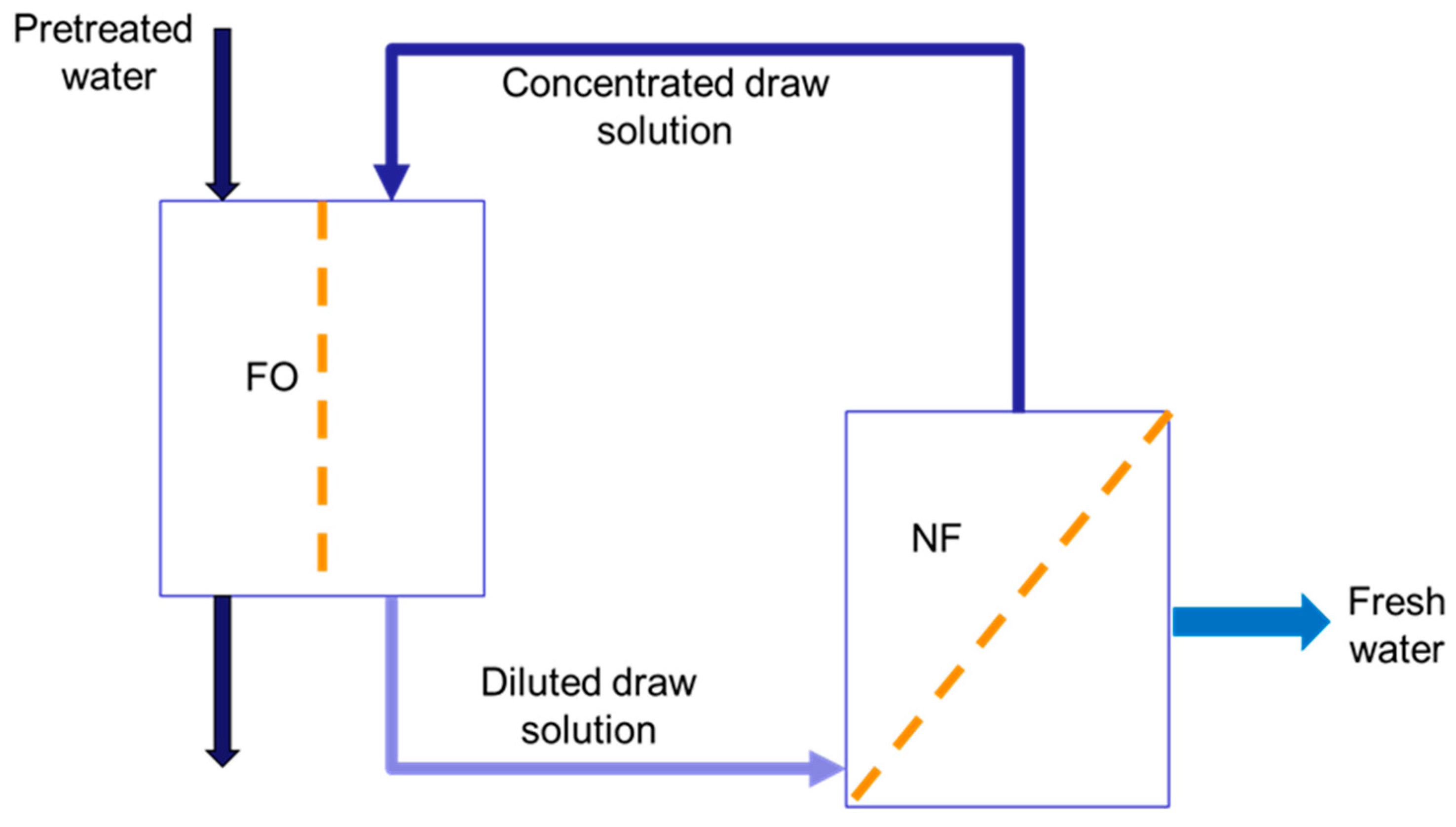
Figure 2.
Progress of dynamic FO experiments using a TFC membrane in the AL-FS orientation; the mass of the feed and draw solutions as a function of time. Draw solution: 1 M MgCl2; feed solution: DI water or aqueous 200 ppm CuSO4⋅5H2O solution. Temperature: 24oC.
Figure 2.
Progress of dynamic FO experiments using a TFC membrane in the AL-FS orientation; the mass of the feed and draw solutions as a function of time. Draw solution: 1 M MgCl2; feed solution: DI water or aqueous 200 ppm CuSO4⋅5H2O solution. Temperature: 24oC.
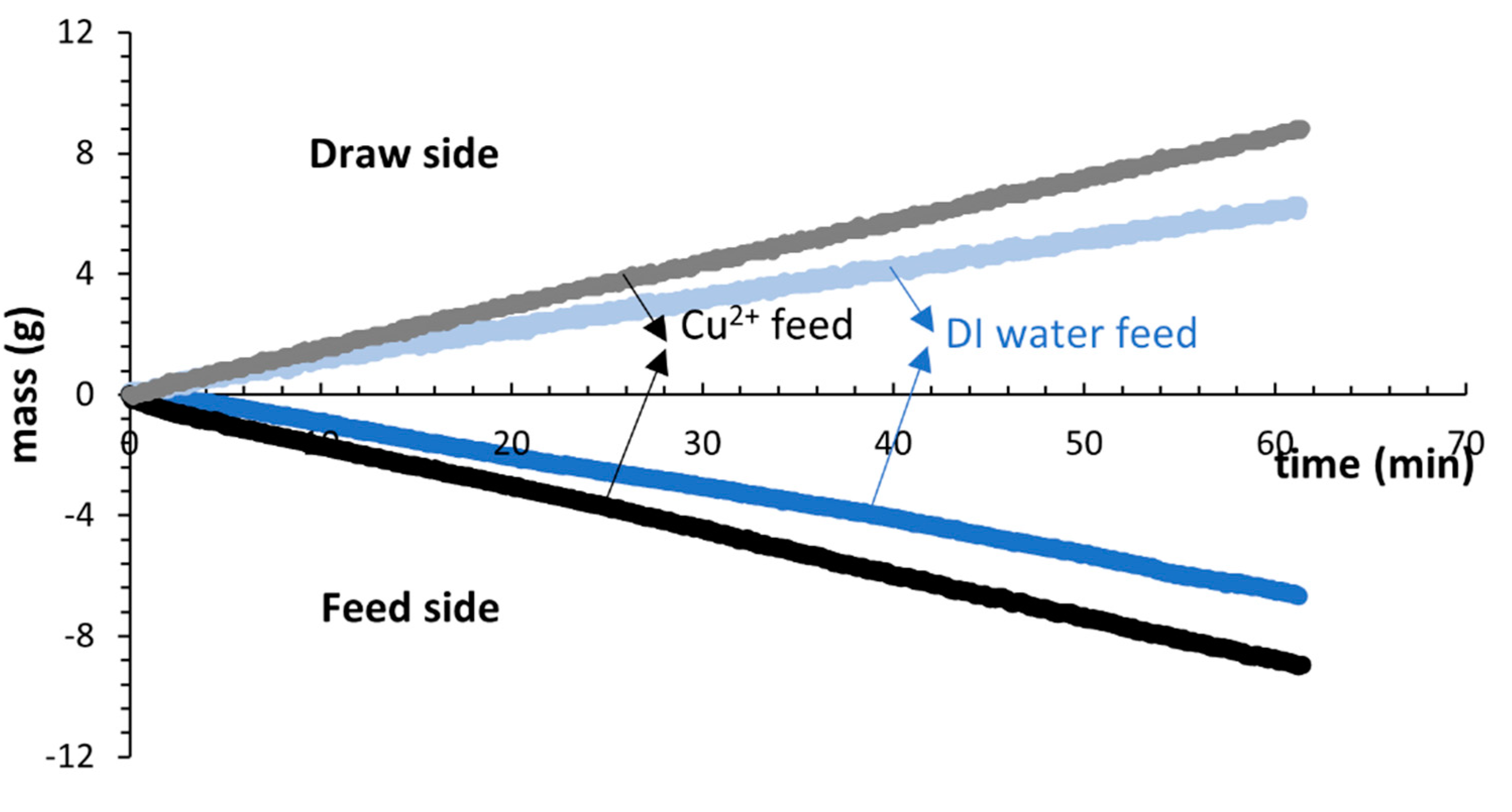
Figure 3.
Progress of dynamic FO experiments using a TFC membrane in the AL-FS orientation; the mass of MgCl2 as a function of time. Draw solution: 1 M MgCl2; feed solution: DI water or aqueous 200 ppm CuSO4⋅5H2O solution. Temperature: 24oC.
Figure 3.
Progress of dynamic FO experiments using a TFC membrane in the AL-FS orientation; the mass of MgCl2 as a function of time. Draw solution: 1 M MgCl2; feed solution: DI water or aqueous 200 ppm CuSO4⋅5H2O solution. Temperature: 24oC.
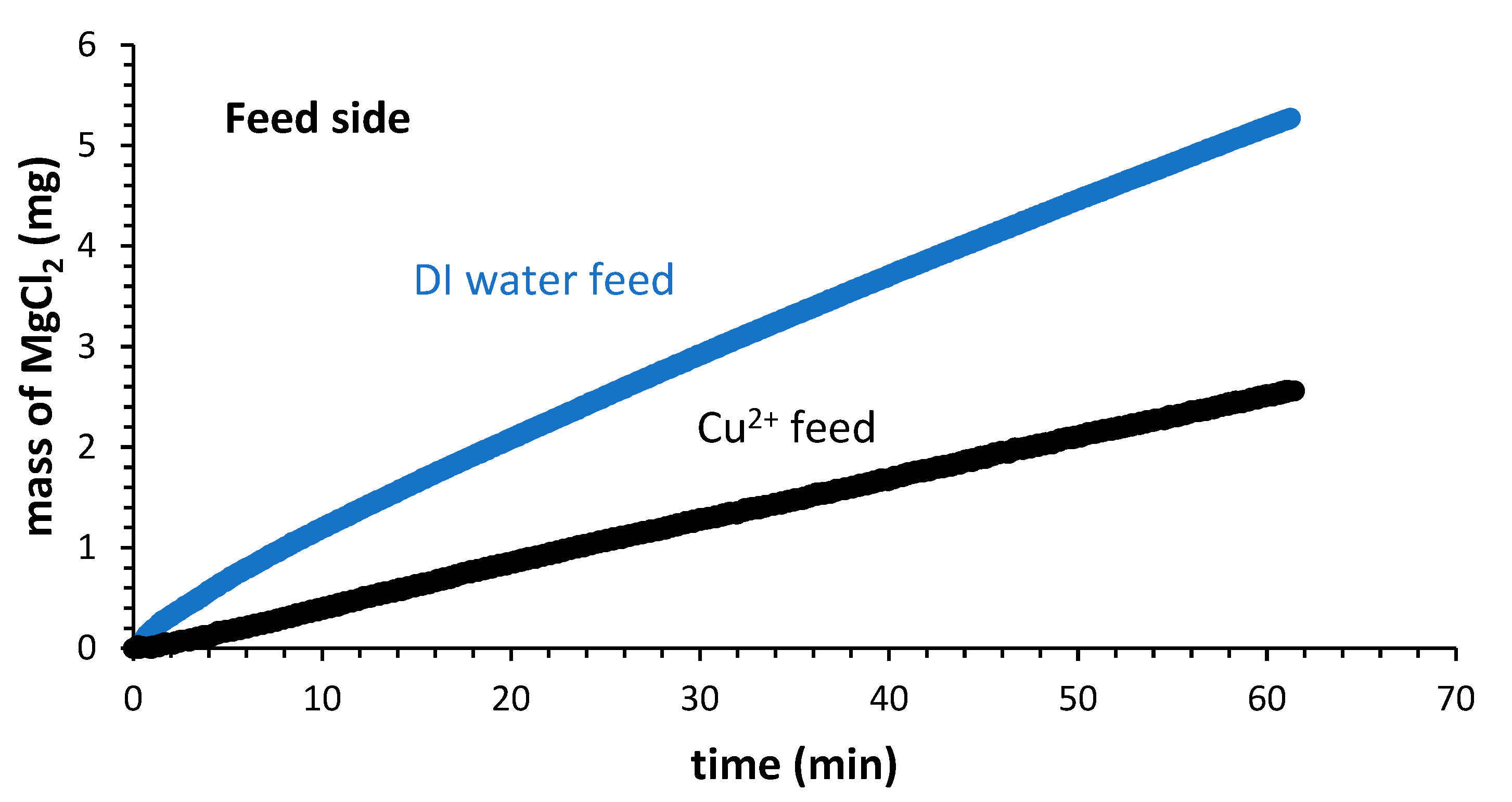
Figure 4.
The average water flux of TFC and TFN membranes using the different feed solutions. Orange: DI water; green: 200 ppm CuSO4⋅5H2O solution; purple: 200 ppm Pb(NO3)2 solution. Draw solution in all experiments: 1 mol/L MgCl2.
Figure 4.
The average water flux of TFC and TFN membranes using the different feed solutions. Orange: DI water; green: 200 ppm CuSO4⋅5H2O solution; purple: 200 ppm Pb(NO3)2 solution. Draw solution in all experiments: 1 mol/L MgCl2.
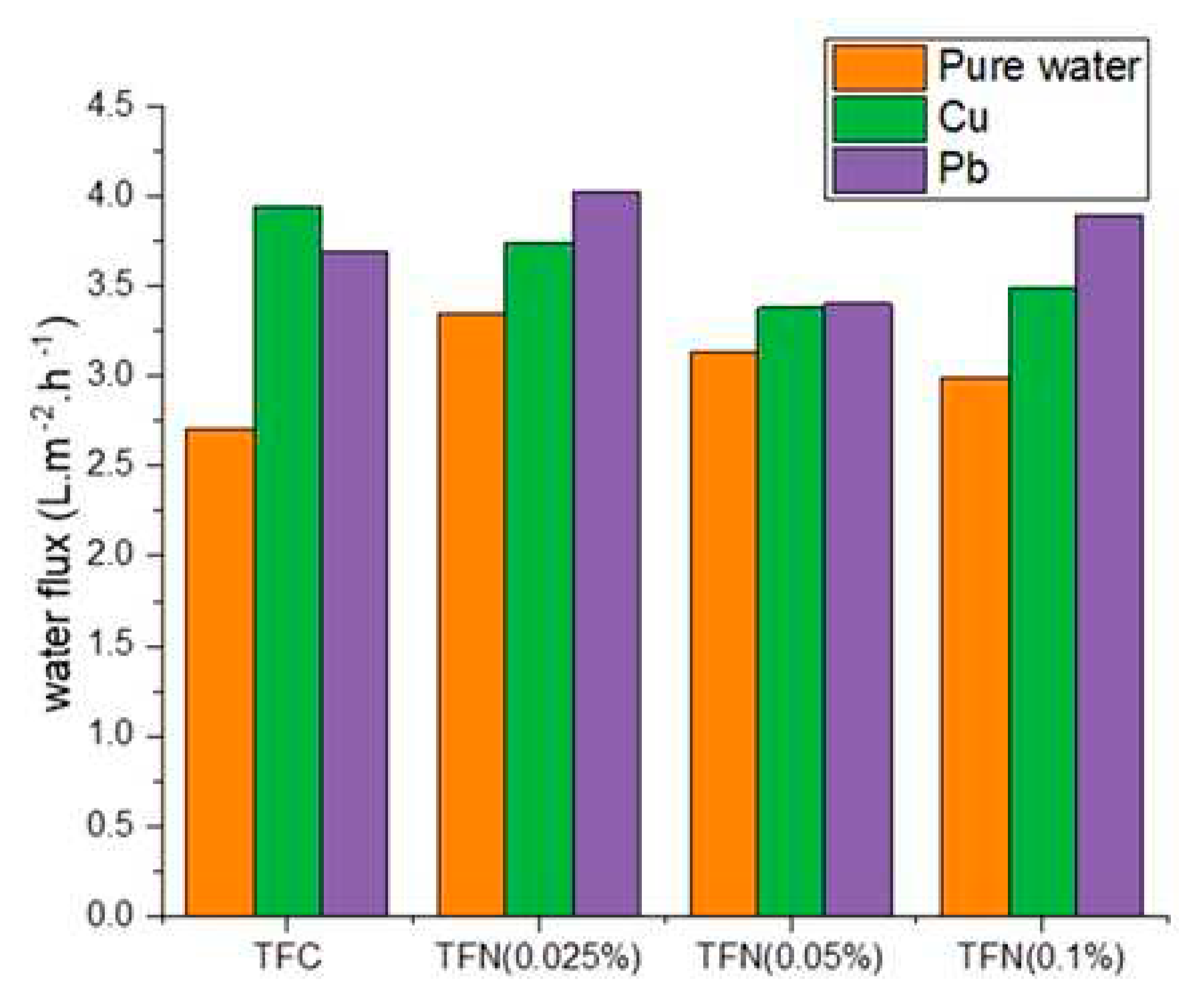
Figure 5.
The average reverse flux of MgCl2 of TFC and TFN membranes using the different feed solutions. Orange: DI water; green: 200 ppm CuSO4⋅5H2O solution; purple: 200 ppm Pb(NO3)2 solution. Draw solution in all experiments: 1 mol/L MgCl2.
Figure 5.
The average reverse flux of MgCl2 of TFC and TFN membranes using the different feed solutions. Orange: DI water; green: 200 ppm CuSO4⋅5H2O solution; purple: 200 ppm Pb(NO3)2 solution. Draw solution in all experiments: 1 mol/L MgCl2.
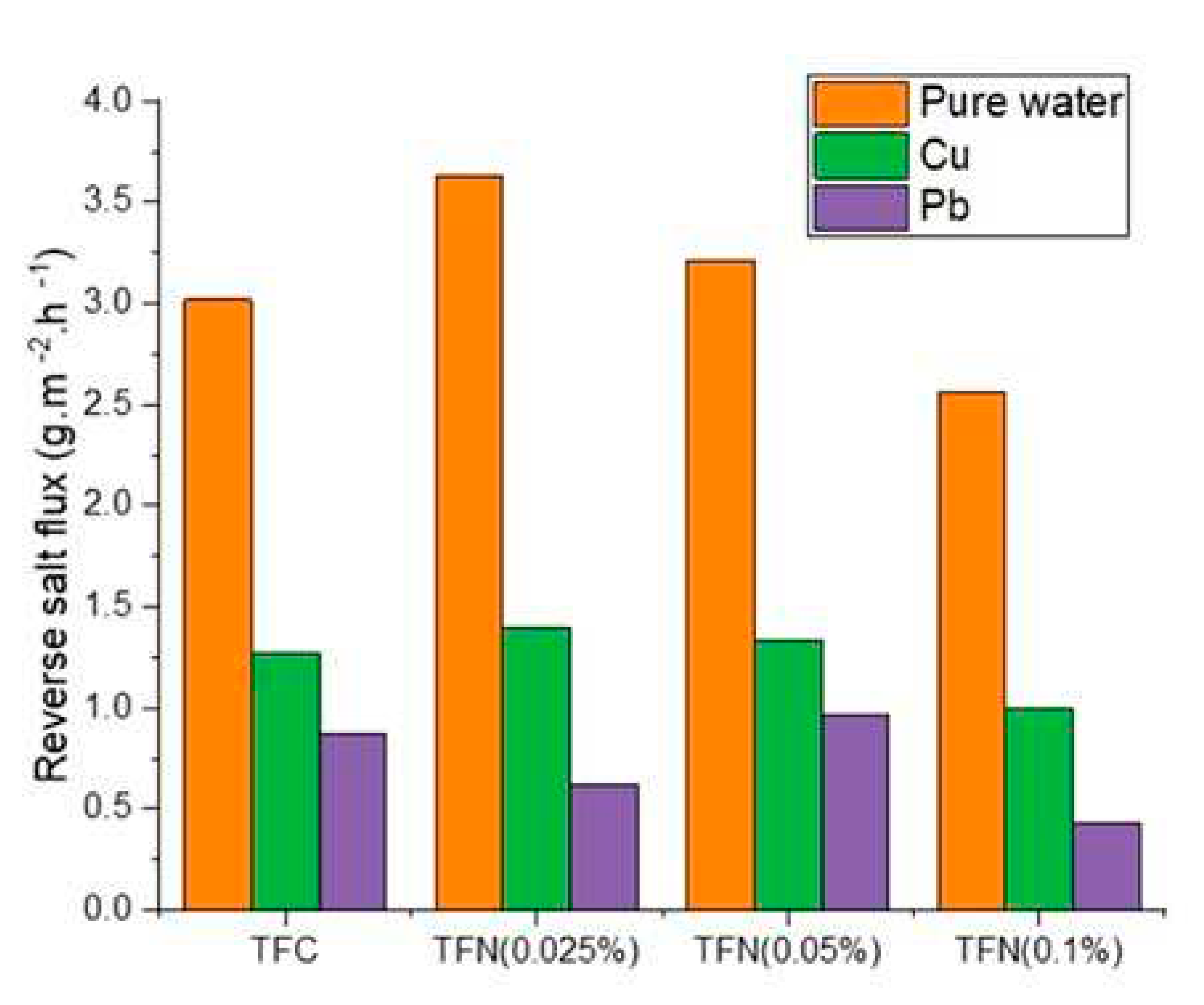
Figure 6.
The average rejections of Cu2+ and Pb2+ by TFC and TFN membranes in FO tests.
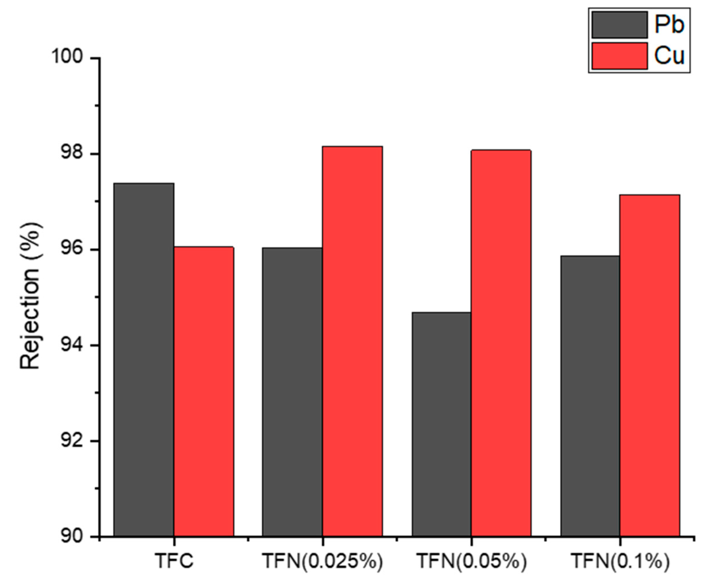

Table 1.
Summary of the ICP analysis and zeta potential analysis of selected membranes before and after the FO experiments.
Table 1.
Summary of the ICP analysis and zeta potential analysis of selected membranes before and after the FO experiments.
| Membrane | Initial zeta potential (mV) | Final zeta potential (mV) | Adsorbed Cu (μg) | ||
|---|---|---|---|---|---|
| DI water feed | Cu2+ in feed | DI water feed | Cu2+ in feed | ||
| TFC | -17.8 | -10.2 | -8.72 | 1.27 | 8.83 |
| TFN(025%) | -20.1 | -15.5 | -14.5 | 8.39 | 10.41 |
Disclaimer/Publisher’s Note: The statements, opinions and data contained in all publications are solely those of the individual author(s) and contributor(s) and not of MDPI and/or the editor(s). MDPI and/or the editor(s) disclaim responsibility for any injury to people or property resulting from any ideas, methods, instructions or products referred to in the content. |
© 2023 by the authors. Licensee MDPI, Basel, Switzerland. This article is an open access article distributed under the terms and conditions of the Creative Commons Attribution (CC BY) license (http://creativecommons.org/licenses/by/4.0/).
Copyright: This open access article is published under a Creative Commons CC BY 4.0 license, which permit the free download, distribution, and reuse, provided that the author and preprint are cited in any reuse.


