Preprint
Article

H–H Configuration of Modular EV Powertrain System Based on the Dual Three-Phase BLDC Motor and Battery-Supercapacitor Power Supply System

Altmetrics

Downloads

126

Views

29

Comments

0

A peer-reviewed article of this preprint also exists.

This version is not peer-reviewed

Submitted:

28 May 2023

Posted:

30 May 2023

You are already at the latest version

Alerts
Abstract
A modular approach to the construction of electric machines, drive systems, power supply systems is a new direction of modern technology development. Especially, the modular approach is promising for electric vehicles due to such positive aspects as increased efficiency, fault tolerance, overall reliability, safety, enhanced control capabilities, etc. In this work, the modular approach is comprehensively applied to an EV powertrain system, which includes a dual three-phase (DTP) BLDC motor with two machine modules of an asymmetric configuration, two battery modules and a supercapacitor module (SCM). The proposed H–H configuration of modular EV powertrain system includes four voltage source inverters that combine the power modules with the open ends of the windings (OEW) of the module machine armature, and provide control of their operation. Based on the developed mode system of the OEW machine module operation for EV traction and braking, a general control algorithm for the proposed configuration of the modular EV powertrain system has been developed. It combines the control of the operating modes with the functions of maintaining the required SOC level of the SCM and equalizing the SOCs of the two battery modules. The conducted simulation and experimental studies confirmed the workability and effectiveness of the proposed solutions.
Keywords: 
Subject: Engineering  -   Transportation Science and Technology

1. Introduction

1.1. Motivation

The main cause of the environmental problems of recent decades, such as global warming and air pollution, is the long-term use of fossil fuels, a large part of which is consumed by vehicles. In recent years, significant efforts have been made to change the situation in the direction of reducing air pollution from transport. Technologies of electrification of existing vehicles are increasingly being used, first, pure electric and hybrid electric vehicles are being developed. In addition, new groups of vehicles are being created, in particular in the area of personal low-power vehicles, as well as mobile robots for various purposes [1]. Since electric vehicles are becoming a key trend in transportation technology, the main requirements for them are their efficiency and reliability. These two indicators can be significantly increased by using a modular approach in the construction of on-board power sources, power converters and electric machines [2,3,4,5].

1.2. Literature Review

Energy storage systems (ESS) are the most critical part of electric vehicles with autonomous on-board power. This is due to the complicated set of requirements for these systems: high absolute and specific (per unit of mass and volume) energy and power, duration of operation (a large number of charge-discharge cycles), non-critical to temperature conditions, as well as low cost. Among the currently known ESSs, the closest to comprehensively meeting these requirements are electrochemical storage batteries (B), in particular of the lithium group [6]. However, they are also characterized by a relatively short service life, the dependence of this term on operating conditions, in particular, the charging time and the values of charge-discharge currents, as well as high cost.
Since the combination of the above requirements for ESSs is not completely provided by any of the known sources or energy accumulators, hybrid energy storage systems (HESS) are often used, consisting, as a rule, of two sources that complement each other. For example: two different types of batteries, B and supercapacitors (SC), fuel cells and SCs, B and superconducting magnetic energy storage (SMES), etc. [7,8,9,10].
Among HESSs, the B–SC system is one of the most successful and effective [8,11,12,13]. In this system, B acts as an energy source, and the SC-pack, composed of a number of SCs, plays the role of a power source, since the specific energy of B is about an order of magnitude higher than that of SC, and the specific power of SC is one order of magnitude higher than that of B. The number of charge-discharge cycles of SC is approximately two orders of magnitude greater than that of the best B, and reaches 0.5...1 million [14]. Therefore, in HESS, the SC-pack must undertake fast-changing and powerful energy exchange processes with the load, while the load B must be long lasting and smoothly variable and, if possible, low. This will provide a significant increase in the B service life [13]. Since, unlike B, chemical reactions do not occur in the SC work, the latter are not critical to the temperature conditions of operation, keeping their properties practically unchanged under real environmental conditions. However, there are additional complications of the system related to the change of SC-pack voltage within wide limits depending on its state of charge (SOC) that needs to use expensive and powerful semiconductor converters. However, despite these complications, as shown in recent studies [15], the use of B–SC HESSs in EVs is economically justified due to the reduction of the required B capacity and the extension of its service life.
Both the electrochemical B cell and the SC are low voltage (a few volts) devices. Therefore, in order to obtain operating voltages in the on-board DC-bus of the EV, which can reach several hundred volts, it is necessary to connect a large number of these devices in series. Such connections cause a voltage imbalance in charge-discharge processes due to the inevitable difference between the parameters of each cell. To eliminate this phenomenon, which will lead to underutilization of some cells and possible overcharging of others, it is necessary to use special systems for equalizing voltages or charges. These systems together with temperature and charge level monitoring systems B and SC-pack form the main part of the energy management systems (EMS) of HESS [16].
To combine B and SC-pack in the HESS design, various system configurations are used using pulsed DC-DC converters as controlled electronic transformers. Currently, a number of configurations of B-SC HESSs have been proposed and investigated, among which semi-active, active, and combined configurations are the most common [17,18].
A fundamentally different group of HESS, which are being developed recently, is built according to the modular principle. Here, relatively low-voltage B modules (BM) or SC-pack modules (SCM) are combined into a powertrain using power semiconductor converters of various topologies. Thanks to the presence of additional control channels of modules, the number of degrees of freedom of the system increases significantly. This makes it possible to put additional functions on the power converters, for example: switching and regulation of the supply voltage, as a rule, multi-level, energy-efficient control of coordinates of electric drive, performance of EMS functions, in particular, equalization of voltages and charges of individual low-voltage modules, etc. The modular approach has a number of other advantages compared to the classic hardware and functional separation of the powertrain into ESS and electric drive system. The main of these advantages concerning EVs are as follows: the low voltage of one module (up to 60 V) simplifies maintenance and makes it safe; this also makes it possible to use cheap MOSFET switches, which efficiently operate at a high PWM frequency (50-100 kHz), that significantly reduces the size of chokes and capacitors in the pulse converter; a smaller number of series connected low-voltage cells simplifies the operation of the EMS; individual power modules are easier to place by distributing the weight over the EV body; during an accident, the probability of a fire is significantly reduced.
Examples of the application of modular HESS in EVs can be seen in various configurations. For example, in [19] cascade DC-DC converters combine low-voltage BMs or hybrid B–SC modules and allow for regulation according to the multi-level principle of DC-voltage for control of the EV motor operation. Another variant of modular power supply and control are modular multilevel inverters, in which the phase voltage applied to the motor armature winding is regulated in a similar way [20]. At the same time, only one stage of the converter works under PWM, which reduces switching losses and reduces electromagnetic interferences. Another example is the modular two-way supply of the open armature winding of a three-phase synchronous machine with permanent magnets (PMSM) through the voltage source inverters (VSI) - the so-called open-end winding (OEW) configuration [21,22]. A number of advantages over the traditional one-sided PMSM power supply characterizes such a solution. These advantages are similar to those of multiphase PMSMs: increased fault tolerance, lower loads on VSI switches, lower voltage of ESS modules, increased number of degrees of freedom. These advantages are achieved due to the rapid increase in the number of state combinations of two VSIs, which is equal to 22n, where n is the number of the machine phases [23]. Thanks to this, it is possible to implement much more sophisticated modulation methods than for a three-phase machine. That allows to significantly reduce current and electromagnetic torque ripples, to more easily implement multi-level control (in particular, three- or four-level using two standard VSIs), and to weaken the excitation for operation in a wider speed range, as well as to ensure operability during possible failures in one of the inverters [24]. All these advantages are very important for the efficient operation of EVs. In addition to the above, the increased number of degrees of freedom can be used for EMS operation, in particular, for equalizing the charges of two BMs feeding the corresponding VSIs. In works [25,26], SC-packs are directly integrated into electric drive systems based on three-phase machines with OEW. The open ends of the windings are connected to two or three-level VSIs, which are fed from B on one side and from SC-pack or even from HESS on the other side. The large number of degrees of freedom allows the same VSIs to be used for both drive control and EMS operation. Similar solutions can also be found in renewable energy, for example, in wind energy conversion systems (WECS), when a transformer winding or an armature winding of a synchronous generator is included as OEW and integrated with HESS with BM and SCM [27].
Further development of the modular approach in the configuration of EV powertrain systems is related to the use of modular designs of multiphase electric machines. Such machines have a number of advantages in their characteristics compared to their three-phase counterparts [28,29,30]. One of the features is the distribution of power over a larger number of phases, and therefore the nominal power per phase is reduced that makes it possible to use cheaper switches. Another feature is the improved distribution of the magnetic movement force (MMF) in the air gap of the machine that increases the electromagnetic torque and reduces its pulsations. Therefore, in general, the efficiency of the drive increases. In addition, the number of degrees of freedom increases in proportion to the number of independent phase variables of the drive that provides such an important function as fault tolerance. The multiphase implementation first spread among asynchronous machines, and more recently for PMSMs.
Among the multi-phase PMSMs, there are those that have two or more three-phase armature winding modules. At the same time, the modules can have a symmetrical configuration, when the MMFs of the windings of the same name coincide in phase, or an asymmetric configuration, when groups of three-phase windings are shifted by a certain angle θ [31]. Since all the windings have a common magnetic wire, there are mutual inductive connections between the windings. In cases of existing nonlinearities (non-sinusoidal MMF, saturation of the magnetic circuit), as well as non-sinusoidal or unequal loading of the modules, due to their magnetic coupling, higher odd harmonics of currents appear, which lead to even harmonics of the electromagnetic torque, and also reduce the speed of torque control. In such cases, asymmetrical windings have advantages in terms of filtering properties for certain harmonics. For example, for two three-phase windings, the optimal angle of their displacement is 30 degrees, which ensures the absence of 6n ± 1 harmonics of the current and 6n harmonics of the electromagnetic torque, where n = 1, 2, ... [32]. In addition, in order to exclude zero-sequence currents, the neutral points of the three-phase windings must be galvanic separated from each other in the case of feeding their VSIs from a common DC-bus. In the case of using galvanic decoupled power supply modules, the neutral points of the windings can be connected.
New promising solutions may have a combination of the modularity of ESS with the modularity of electric machines, which has recently become widespread in applications responsible for efficiency and reliability, in particular in aviation and transport, where the electric drive wins the place of the thermal one [33,34]. However, such complex modular solutions lead to a significant complication of EV powertrains, in particular their energy management. In our research, in order to simplify the modular powertrain, we apply the principle of operation of the brushless DC motor (BLDCM). For this, the simplest synchronous machine with permanent magnets placed on the surface of the rotor is used, and the switching of armature windings is carried out by the signals of cheap point Hall sensors mounted in the machine. This work is dedicated to the further development of this specified direction of research.

1.3. Scientific Contributions

The main contribution of this paper is the proposal of a new configuration of a modular powertrain for EV, which includes both a modular DTP BLDCM of an asymmetric configuration and a modular on-board B-SC HESS. For such a powertrain configuration, a detailed analysis of the possible modes of its operation was carried out. In particular, the development of the OEW mode switching system for the DTP BLDCM and the algorithm of such a control system, which allows simultaneously control the electric drive system and perform EMS functions – balancing the SOCs of the battery modules and maintaining the SOC of the SC module in the given range.
This paper is organized as follows. Section 2 briefly describes different modular system configurations developed by the authors in their previous studies and highlights the scheme and futures of the proposed H–H configuration of modular powertrain system. Development of the control system for the switching of the DTP BLDCM modules, as well as the development of the algorithm of the EMS are presented in Section 3. In Section 4, the computer model of the studies modular powertrain system in Matlab/Simulink environment was developed, the simulation results are shown and their discussion is carried out. Experimental test is described in Section 5. Conclusions and future work are in Section 6.

2. System Configuration and Its Preferences

2.1. Brief Review of Our Previous Studies

Modular configurations of on-board power systems were first studied, which consisted of four BMs [35] and five hybrid B–SC modular HESS [36], which were combined using half-bridge modules in a cascaded converter that fed and regulated according to a multi-level principle of DC voltage, which, in turn, fed the VSI of BLDCM. At the same time, the VSI provided only low frequency switching of the motor armature windings according to the rotor position. The next was a configuration with a modular multi-level inverter [37], where in each phase of the BLDCM, two full-bridge modules were connected in series, thus combining six BMs and making it possible to adjust the voltage applied to the two sequentially connected phases of the motor according to the four-level principle. In all these works, the main attention was focused on the development of algorithms for controlling semiconductor switches of modular converters, which simultaneously controlled the complex of energy supply and electric drive of EV. In particular, for each of the studied modular configurations, a BLDCM electromagnetic torque and angular velocity control system was developed, which included converter switches control algorithms for positional switching of the armature winding and multi-level regulation of the corresponding motor supply voltages. In accordance with other developed algorithms, the same switches provided the EMS function – leveled the charges of BMs and/or SCMs.
The following investigated configuration is promising for EVs – inverter-fed OEW BLDCM, shown in Figure 1, which combines one BM and one SCM, which through their inverters VSI 1 and VSI 2 are connected to the open ends of the motor armature winding [38]. With the help of different switching options of the inverter switches in different EV operating modes, the motor armature winding can be connected either to the BM or to the SCM at low EV speeds, or to two modules at the same time with the summation of their voltages at high EV speeds. During the regenerative braking of the drive, it is also possible to transfer the braking energy to the required power module. As a result of the research, inverter control algorithms were developed to ensure all modes of operation of the EV drive, as well as EMS to equalize the module charges.
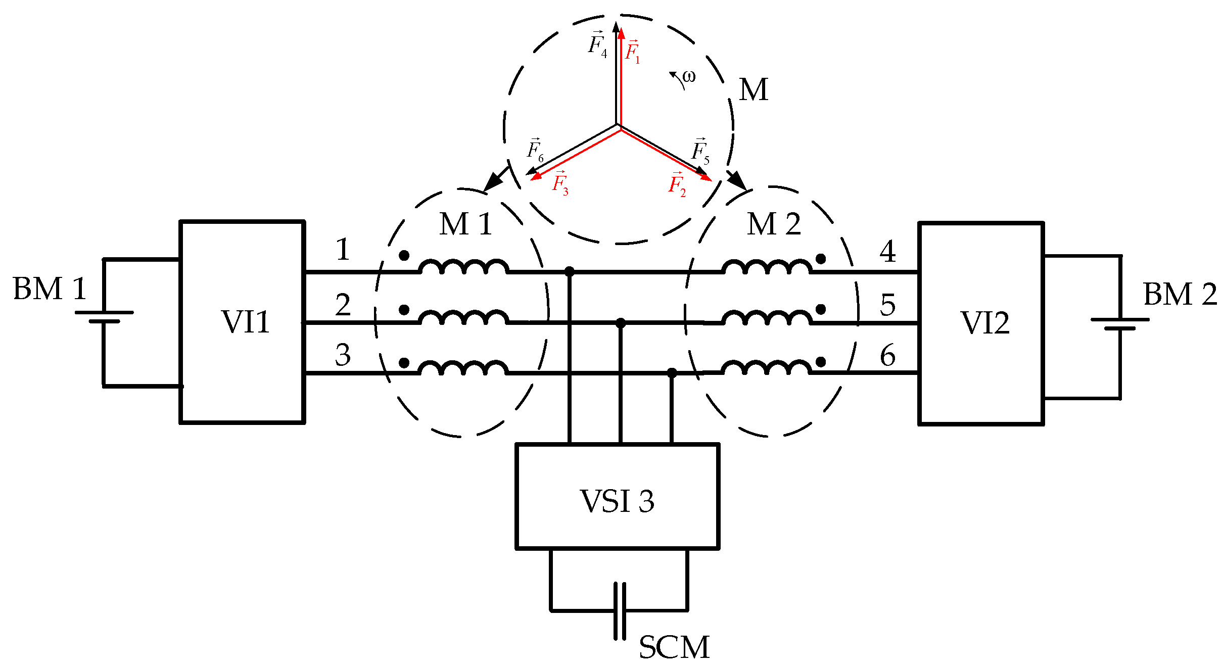
In the following modular powertrain configuration, the aforementioned dual inverter-fed OEW BLDCM configuration is developed for use in a modular dual three-phase (DTP) BLDC drive [39]. As in the previous configuration, each of the two sets of armature winding of DTP BLDCM is open at both ends, which made it possible to connect three VSIs to them, as shown in Figure 2. In such a configuration, which we called T configuration, each of the two sets of armature winding can work independently in light EV operation modes, with both one-way and two-way power supply. In addition, in heavy EV driving or downhill driving modes, the two modules can also work together with one-way or two-way power supply. Such advanced capabilities make it possible to ensure efficient operation of the EV drive in all operating modes. When both winding sets are connected together to the SCM, control of their currents is possible only if the phases of the same name are in phase, that is, with the symmetrical DTP BLDCM configuration. This is shown in the vector diagram of phase MMFs of two three-phase sets 1, 2, 3 and 4, 5, 6 in the circle at the top in Figure 2. The paper also shows how it is possible to realize the pre-charging of the SCM before driving, as well as to control the charging or discharging processes of the SCM during the operation of the EV.

2.2. Proposed H–H Configuration of Modular Powertrain System

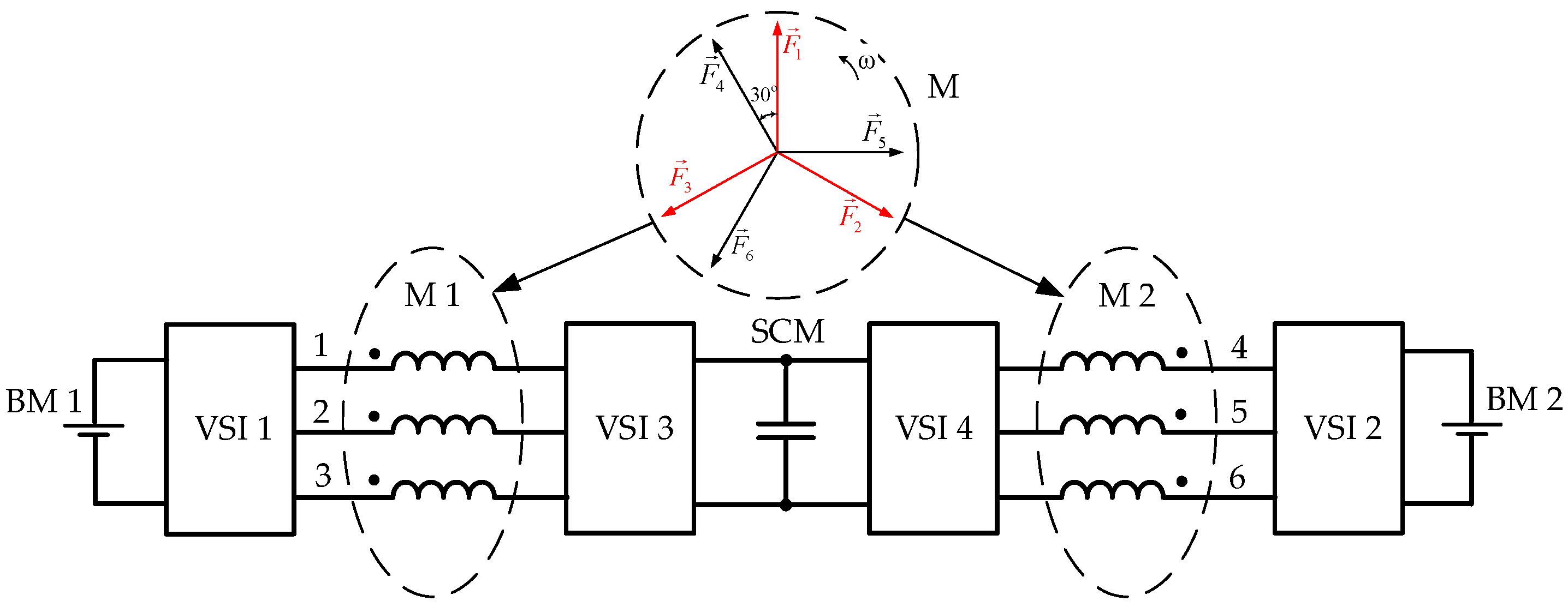
The main disadvantage of the modular powertrain system shown in Figure 2 is its intended for work with DTP BLDCM of a symmetrical configuration, which causes increased pulsations of the electromagnetic torque of the drive. To eliminate this shortcoming, in this work, a new modular powertrain system for EV based on DTP BLDCM of asymmetric configuration is proposed (see Figure 3). In it, the DTP synchronous PM machine has winding sets M 1 and M 2 offset from each other by an optimal angle of 30o, as shown in the vector diagram of the phase MMFs in the circle at the top in Figure 3. Each of the winding sets is turned on according to the OEW system, and four VSIs – VSI 1 and VSI 3, VSI 2 and VSI 4 – are connected to the beginnings and ends of the armature winding modules M 1 and M 2. To the inverters VSI 1 and VSI 2, which are connected to the beginnings of the armature winding modules, two battery modules BM 1 and BM 2 are connected. Inverters VSI 3 and VSI 4, which are connected to the ends of the armature winding modules, are interconnected on the sides of the DC voltage to which the SCM is connected. Considering the topology of the proposed powertrain system, we can call it the H–H configuration.
The proposed modular powertrain system with HESS has the ability to work in a number of modes that differ in the number of included modules of the armature winding of the electric motor and their electrical power supply. The latter can be carried out separately from both its BM and SCM, as well as simultaneously from both of these devices, providing bidirectional power to the module armature winding. VSIs switches depending on the EV operating modes carry out switching to each of the specified operating modes.
Thus, during EV start-up and acceleration, when a large traction force is required, the two BLDCM armature-winding modules consume a large current from the SCM for a short period through the working inverters VSI 3 and VSI 4. At the same time, the inverters VSI 1 and VSI 2 are switched in “zero- mode", which on the side of DC voltage disconnects them from BMs, and on the side of alternating voltage ensures that all phases of the armature-winding modules are closed to each other through semiconductor switches forming a star connection of the modules.
At low EV speeds, the armature-winding modules are powered from their BMs through the working inverters VSI 1 and VSI 2. At the same time, the inverters VSI 3 and VSI 4 are switched in “zero mode”. Depending on the required traction force, only one armature-winding module can work, or two modules in parallel. SCM is disabled in this mode.
To ensure EV high-speed mode, one of the armature-winding modules must be energized on both sides when the voltages of the corresponding BM and SCM are added. So, if the armature-winding module M 1 is working, it is energized from both sides: from the side of the beginnings of the module winding from the BM 1 through the VSI 1 inverter, and from the side of the ends of the module winding from the SCM through the VSI 3 inverter.
As will be shown below, the proposed H–H configuration of powertrain with DTP BLDCM enables an energy management of power supply modules. For this, a special algorithm of the EMS has been developed to maintain the SOC of the SCM at a given level, when the latter will always be ready both to power the armature-winding modules during acceleration and to absorb the energy of regenerative braking. In addition, the algorithm also provides the equalization of the charges of the BM 1 and BM 2.

2.2. Description of Scheme of the Modular Powertrain of Н–Н configuration

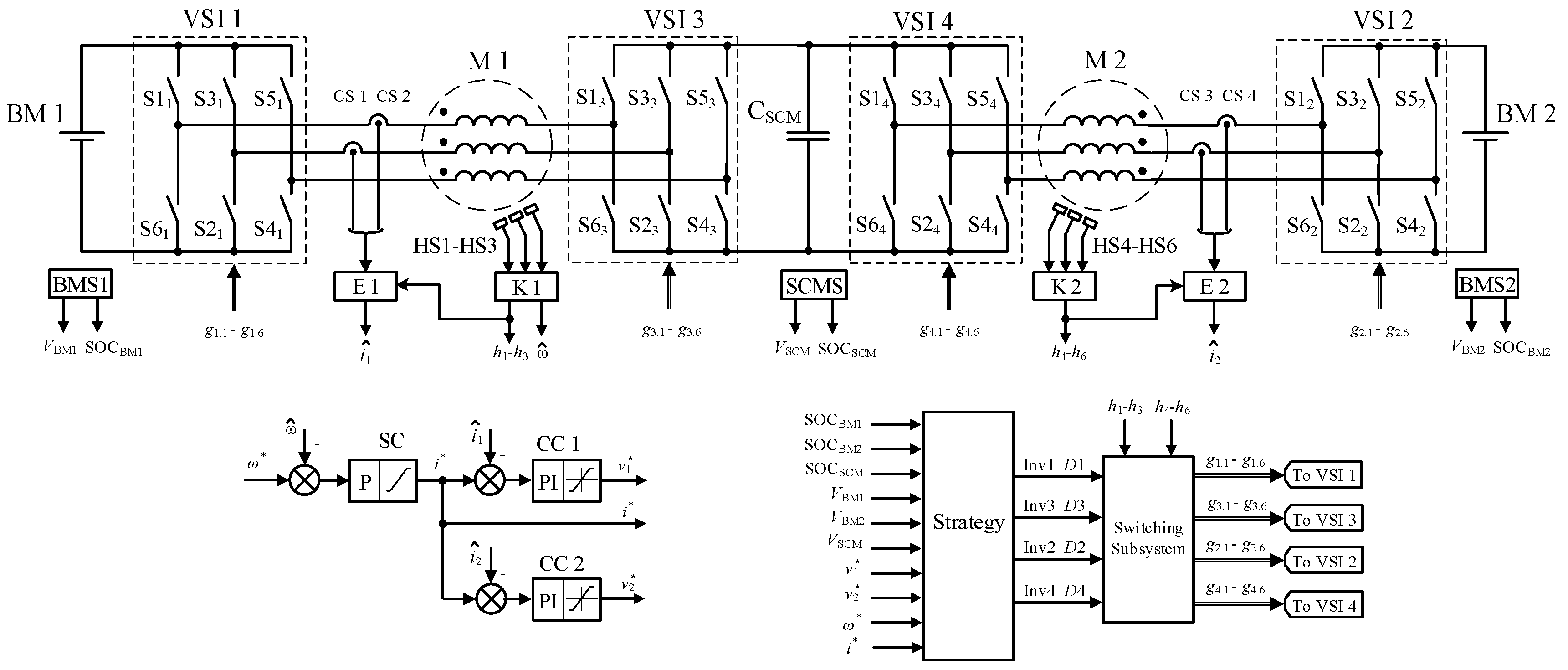
The general scheme of the proposed H–H modular powertrain with a DTP BLDCM and B-SC HESS is presented in Figure 4.
In addition to the main components of the power circuit of the system already described above, the main sensors necessary for the operation of the system are also shown in the upper part.
Each of the power modules is equipped with its own energy management subsystems – BMS 1, BMS 2, and SCMS. At the output of these subsystems, the current values of the voltages of each of the modules and their SOC are obtained, which are then sent to the Strategy subsystem, in which the EMS of the entire EV powertrain system is implemented.
To ensure the positional switching of the armature-winding modules, each of the modules is equipped and synchronized with its system of three Hall position sensors placed at 60o el. apart: HS1 – HS3 for the module M 1 and HS4 – HS6 for the module M 2. From the received from these sensors signals, the respective controllers K 1 and K 2 form at their outputs two three-phase systems of signals with a duration of 120o el., h1 - h3 and h4 - h6, which are used for low frequency switching of currents in their armature-winding modules. At the same time, the controllers K 1 and K 2 calculate the current value of the angular velocity ω ^   of the BLDCM. The estimators E 1 and E 2 calculate equivalent values of DC currents i ^ 1 and i ^ 2 in modules according to the method described in [37]. For this, signals from current sensors in two phases of each of the armature-winding modules are used, the CS 1 and CS 2 for the module M 1 and the CS 3 and CS 4 for the module M 2, as well as the signals h1 - h3 and h4 - h6 formed by the controllers K 1 and K 2.

3. Control System Development

The EV powertrain control system (see Figure 4) includes the angular velocity control subsystem, the current control subsystems of each of the DTP BLDCM modules, the module switching subsystem using voltage inverters – Switching Subsystem, as well as the Strategy subsystem for controlling the operating modes and performing EMS functions.

3.1. Speed and Torque Control Subsystems

The angular velocity control system is built according to the classic two-loop structure of coordinate control (Figure 4). At the input of the proportional speed controller SC, the reference angular velocity signal ω* is compared with the negative feedback signal based on the estimated angular velocity of the motor rotor ω ^ . At the output of the speed controller, a task for the currents of the modules i* is formed. Limits are imposed on the maximum and minimum values of the output signal of the SC, which determine the maximum values of the electromagnetic torque of the BLDCM in traction and braking modes. To ensure maximum efficiency during the operation of both modules, it is necessary that the modules are equally loaded electromagnetically, that is, the equivalent currents in each of the modules must be equal. For this purpose, the same value of the reference current i* is applied to the inputs of the current controllers of each module CC 1 and CC 2. It is compared with the current negative feedback signals i ^ 1 and i ^ 2 of the corresponding module, which are calculated for each of the modules by their estimators E 1 and E 2. At the outputs of the current controllers CC 1 and CC 2, references of armature voltage values are formed for each of the modules – v*1 and v*2, respectively. The magnitude of these output signals is limited by the sum of the maximum voltages of the BM and SCM modules.

3.2. Switching Subsystem of the DTP BLDCM modules

The Switching Subsystem (Figure 4) generates control signals gі.1 - gі.6 for each i-th VSI based on the values of the positional switching signals of each of the armature-winding modules h1 - h3 and h4 - h6, the values of PWM duty ratios Di and the modes of the inverters operation Inv i.
The six-step switching of the armature windings of the BLDCM modules M 1 and M 2 is carried out according to the 120-degree conduction law of each of the switches. Since the windings of the modules are offset by 30o el., the corresponding offset is necessary for commutation of the armature-winding modules. For the VSI 1 and VSI 2 inverters, which are connected to the beginnings of the armature windings of the M 1 and M 2 modules, the winding switching order for an electric machine of an asymmetric configuration for the traction mode of operation is given in Table 1 [31]. Similarly, Table 2 shows the switching order for the VSI 3 and VSI 4 inverters.
To ensure all possible modes of operation in the proposed EV powertrain configuration, each of the four inverters can operate in one of the four modes of operation, which will be denoted by numbers from 1 to 4, as shown in Table 3.
In mode 1, all VSI switches are open. Therefore, the power supply module connected to this inverter cannot operate on discharge. In mode 2, the three switches of the upper group (S1, S3, S5) in the VSI are closed and the lower group (S2, S4, S6) are open, or vice versa. The closed switches and freewheeling diodes provide paths for currents to flow through all phases of the armature-winding module connected to the inverter in both directions, that equivalent to shorting the corresponding end of the armature-winding module. In mode 2, energy from the source connected to the inverter is also not consumed. In mode 3, the traditional switching for BLDCM is carried out, according to the control signals g1 - g6 of the rotor position, ensuring the 120-degree conductivity of all the inverter switches with simultaneous PWM voltage regulation according to the set signal of the duty ratio D. Mode 4 provides only positional switching of the armature winding according to the 120-degree control law without voltage regulation.
Table 4 presents 7 switching modes of the OEW machine module of the DTP BLDCM, which are provided by different switching states of the two inverters and are useful for EV operation in traction mode. For each of the given modes, it is shown which signs have the DC currents iDC of each of the VSIs, that is, the currents of the corresponding power supply modules – BM and SCM connected to the inverters on each side of the machine modules. In mode 0, these currents are equal to zero, because all switches of both VSIs are open (they are in state 1 according to Table 3). For the remaining modes, the BM and SCM currents of the power supply modules may be different, as well as the corresponding functions of these modules (Table 5), which will be useful for developing the EMS.
In the operating modes 1 and 2 of machine modules, one-way power supply of the winding set takes place from the BM or SCM side, respectively. At the same time, the maximum values of the phase voltages of the modular-armature winding and, accordingly, the angular velocity of the BLDCM are limited by the corresponding voltage levels of the BM or SCM. BLDCM speed regulation in these modes, which is carried out using the PWM of the VSI, is possible in the range from zero to the nominal value ωn, which corresponds to the one-way power supply of the armature-winding module (in Table 4, such a speed regulation range is indicated as I zone).
In modes 3 and 4, speed control is also provided in I zone range, but VSIs on both sides of the machine module operate together already. On the one side, the VSI is in state 4, that is, it performs only low-frequency positional switching. On the other side, the VSI operates in mode 3 with PWM armature voltage regulation, but the low frequency switching of its switches is inversely compared to the corresponding switches of the VSI on the other side. Since this VSI switching mode is characteristic for braking, it is indicated in Table 4 as -3, and the corresponding current of the module power supply will have a negative value. In this case, the phase voltages of the armature-winding module will be formed as the differences between the maximum voltages generated by the VSI operating in state 4 and the regulated voltages generated by the VSI operating in state -3.
The modes of operation 5 and 6 of machine modules are similar to, respectively, modes 3 and 4, but here VSIs already work in states 4 and 3, when the addition of phase voltages of the armature winding, which are formed by these inverters, is ensured. At the same time, there is current consumption from both power supply modules, while less consumption will be from the side whose VSI performs PWM regulation.
As can be seen from the above, in all modes of operation of the OEW machine module, only one of the VSIs works with PWM, which reduces switching energy losses in voltage inverters. This approach also makes it possible to obtain multi-level voltage regulation during the operation of the drive in the II zone, which, in addition to the energy advantage, also provides a decrease in the value of dV/dt and, accordingly, a decrease in electromagnetic interference.
Similar to the operating modes of the OEW machine module during EV traction, in Table 6, the modes of operation of such a module during EV braking, when the BLDCM recovers the braking energy to the energy supply modules, are developed. Table 7 shows the characteristics of these modes. Similarly to the previous case, there are also options for transferring braking energy to one of the BM or SCM modules during BLDCM speed regulation in I zone (modes 1 and 2), as well as to both power supply modules during BLDCM speed regulation in II zone (modes 5 and 6). In addition, during braking, you can also discharge the desired power module, increasing the charging current of the other one, when using modes 3 and 4.

3.3.Operation Mode Control Subsystem and EMS (Strategy)

The Strategy block (Figure 4) implements the current regulation algorithms of each of the DTP BLDCM modules, controls the operation modes of the powertrain and performs the main EMS function related to ensuring the required SOC values of the power supply modules. At the inputs of this block, there are the values of the reference current i* and the reference voltages v*1 and v*2 of the modules, the values of the charge levels of the energy sources - SOCBM1, SOCBM2 and SOCSCM, as well as the values of the current voltages of the energy sources - VMB1, VBM2 and VSCM. The output values of this block are the sets for all four VSIs: the modes of operation of the inverters Inv1 - Inv4 and the values of the duty ratios of their PWM D1 – D4.
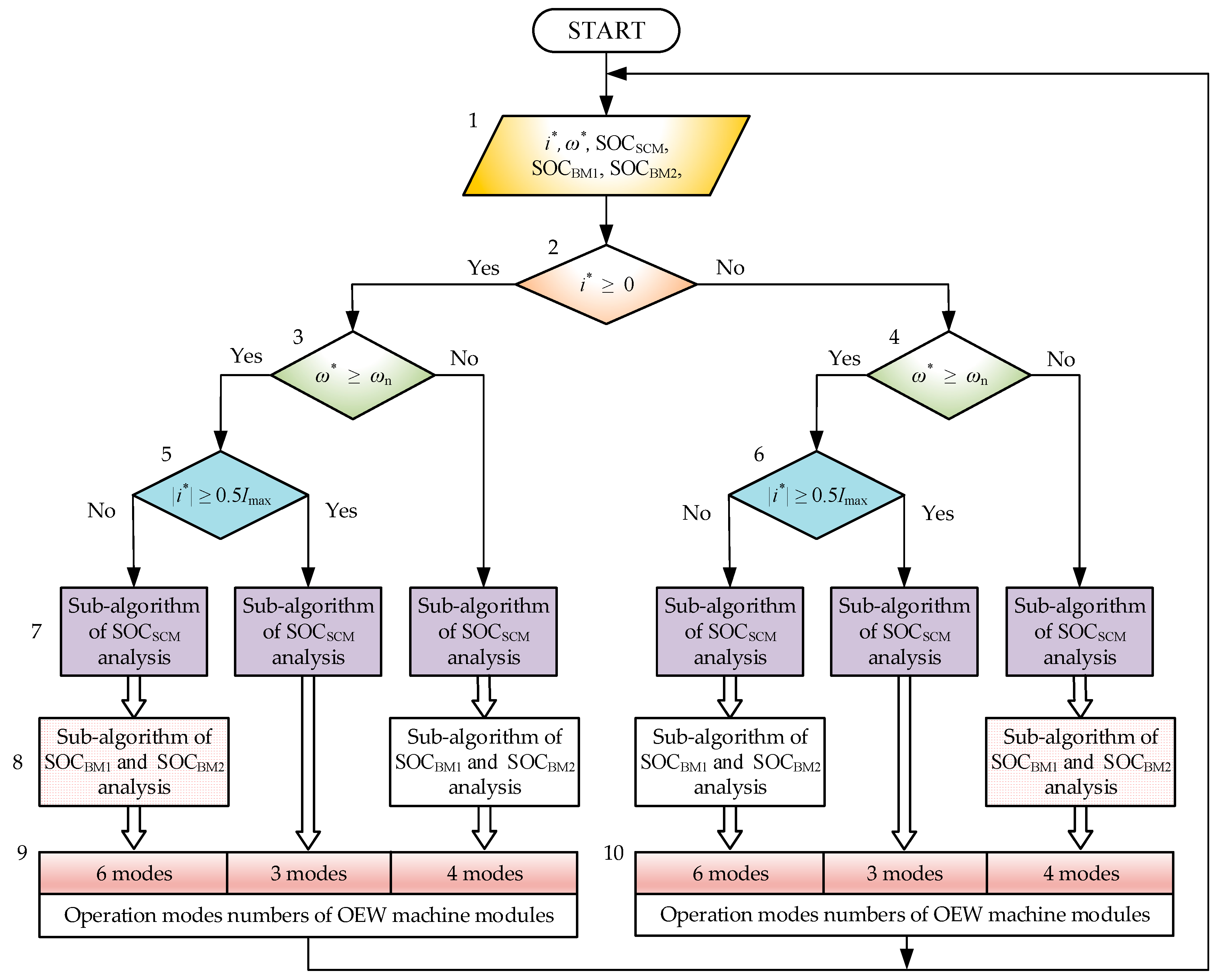
The proposed modular EV powertrain system with hybrid electric power supply has the ability to work in a number of modes that differ among themselves in the number of operated armature-winding modules and their electric power supply. The block diagram of the general algorithm for controlling the DTP BLDCM operating modes and EMS is shown in Figure 5. The general algorithm divides the calculation path according to the following characteristics: the EV operating mode - traction or braking (block 2), the BLDCM speed control range - I or II zones (blocks 3 and 4), the drive load - small or large (blocks 5 and 6). For each of the six combinations formed depending on these features, the Sub-algorithm of SOCSCM analysis (blocks 7) and Sub-algorithm of SOCBM1 and SOCBM2 analysis (blocks 8) are then sequentially performed. Based on the results of this analysis, one of the EV modular powertrain operating modes is selected, which are included in the Operation modes numbers of OEW machine modules (blocks 9 and 10).
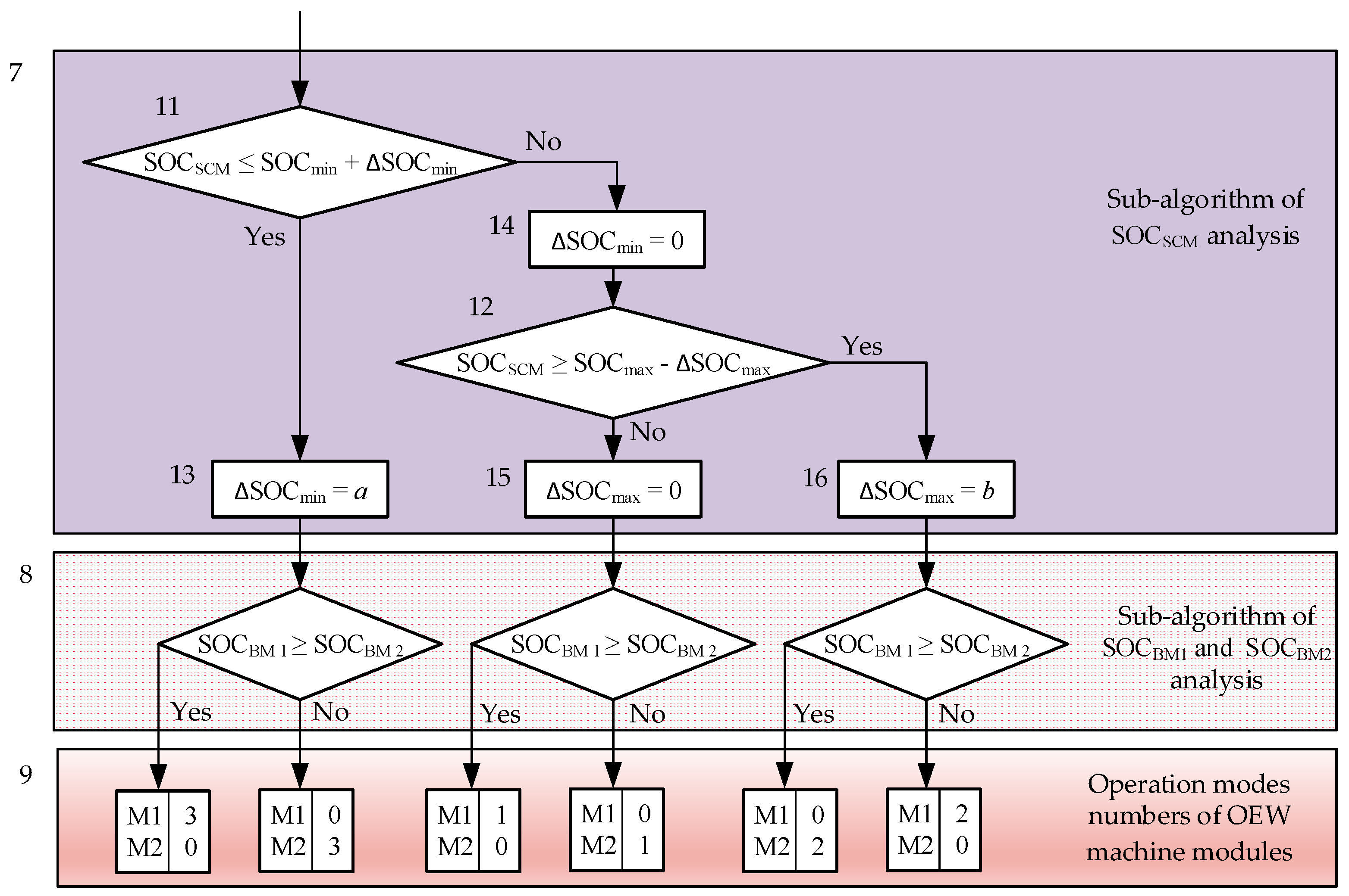
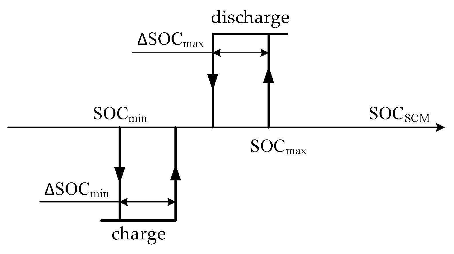
Figure 6 shows in full a fragment of the block diagram of the general control algorithm and SEM for one of the six cases (the first from the left in Figure 5) for the following features: EV traction mode, low speed DTP BLDCM (I zone) and light drive load. Blocks 11 and 12 in the Sub-algorithm of SOCSCM analysis determine in which zone the current value of SOCSCM falls in relation to the set values of the desired range from SOCmin to SOCmax, which is shown in Figure 7. After decreasing the SOCSCM below SOCmin or increasing the SOCSCM above SOCmax, another modular powertrain operation strategy is selected, aimed at charging and discharging the SCM, respectively. Further output from these modes occurs according to the hysteresis principle with the given values of the hysteresis width ΔSOCmin and ΔSOCmax, respectively. In the algorithm, the blocks 13 – 15 perform a hysteresis function. Depending on the ratio of the current values of SOCBM1 and SOCBM2 (block 8), the following operating modes of OEW machine modules are selected from Table 4, which simultaneously provide the required operating mode of the drive and the SCM charging from the BM with a higher SOC or discharging to the BM with a lower SOC.
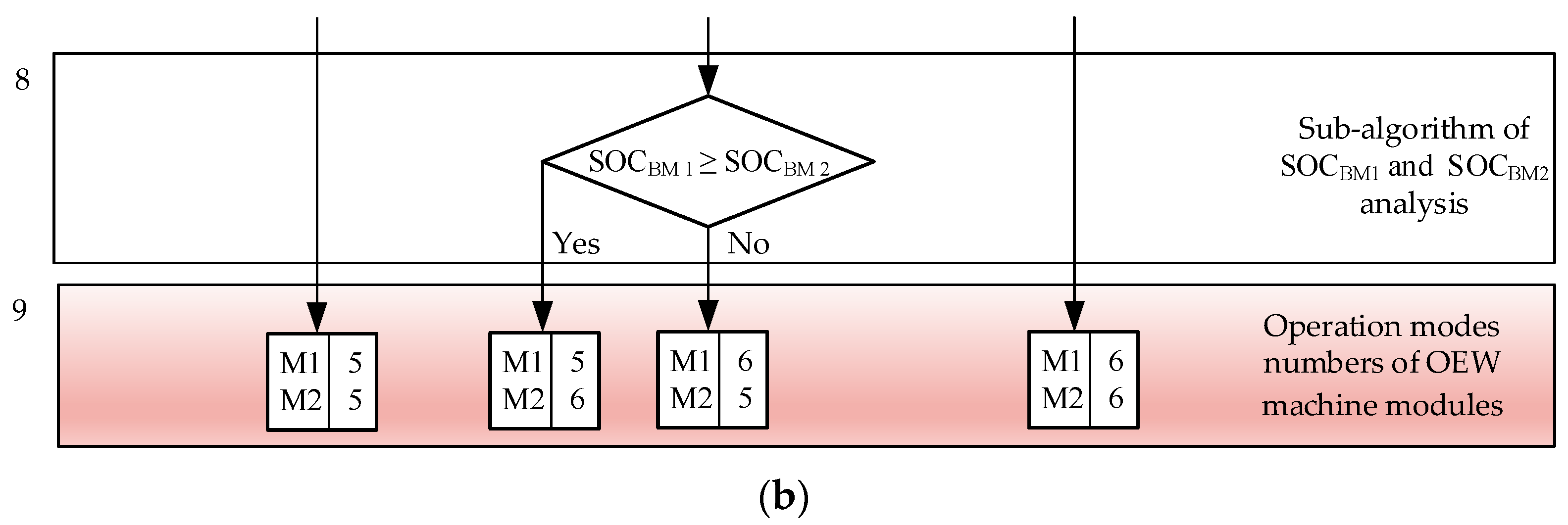
For the other two modes of operation of the modular powertrain, when the EV operates in traction mode, fragments of the block diagram of the general control algorithm and EMS are shown in Figure 8 (without the Sub-algorithm of SOCSCM analysis blocks, which are the same as in Figure 6). Since for a heavy load (Figure 8(a)) two modules of the armature winding must work in the same modes, the Sub-algorithm of SOCBM1 and SOCBM2 analysis (blocks 8) is absent in this version. If the DTP BLDCM operates at high angular velocities, in zone II (Figure 8(b)), some alignment of SOCBM1 and SOCBM2 is also possible, but only if the current value of SOCSCM is in the given optimal zone.
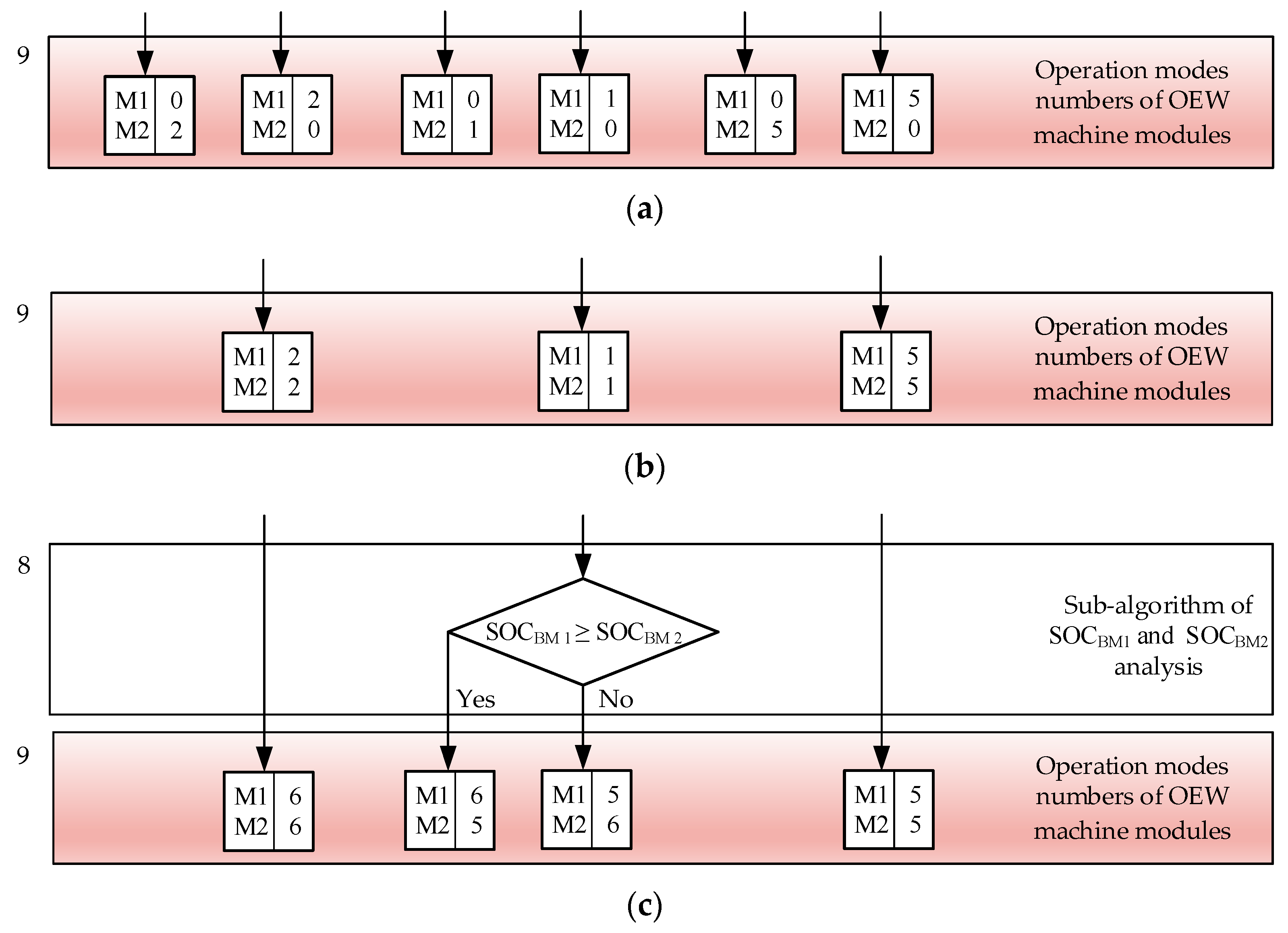
Similarly to the traction mode of EV operation, corresponding work algorithms have been developed for EV braking mode (the right part of the block diagram of the general algorithm shown in Figure 5). Fragments of these algorithms, different from the previous ones, for three combinations of angular velocity and drive load, similar to the EV traction mode, are shown in Figure 9. As in the previous case, all these fragments do not include the same Sub-algorithm of SOCSCM analysis block (block 7 in Figure 6), as well as the Sub-algorithm of SOCBM1 and SOCBM2 block (block 8 in Figure 6), however, only for the fragment shown in Figure 9(a).

4. Simulation Results and Their Discussion

4.1. EV Powertrain Model Description

In this work, simulation studies were carried out with DTP PMSM, the detailed circular mathematical model of which is presented in [40]. This model is developed based on the results of numerical 2D FEM simulation of the magnetic field of a real external rotor machine. According to the developed method, the dependences of self-inductances and mutual inductances on the angle of rotation of the rotor was determined for various variants of module loads, in particular, both mutual inductances between phase windings in one machine module and all mutual inductances between phase windings of different machine modules. Based on the obtained results, a mathematical model of DTP BLDCM in phase coordinates was built, which allows you first to find the corresponding components of the armature currents by integrating six differential equations, and then calculate the current value of the electromagnetic torque based on the obtained current values. The full dynamic model of the studied electric machine is implemented in the Matlab/Simulink environment. The computer model created at the accepted assumptions has a relatively higher level of adequacy, which is confirmed by the corresponding waveforms taken experimentally on a mock-up sample of the electric drive system [40]. At the same time, this computer model demonstrated high performance for simulation on a personal computer. The main parameters of the studied DTP BLDCM, built based on the specified circular model, are presented in Table 8.
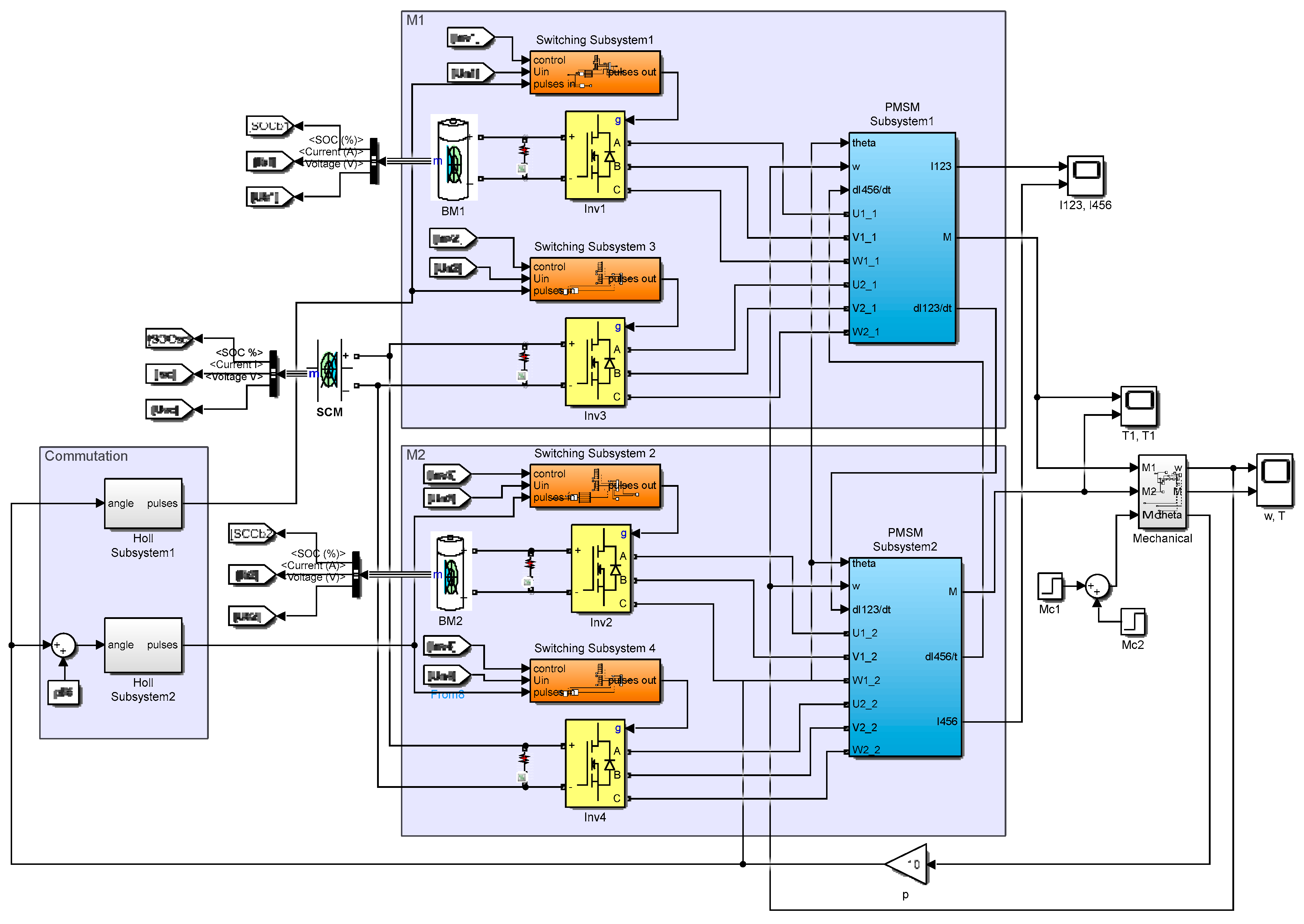
Figure 10 shows the main fragment of the computer model of the proposed H–H powertrain configuration, which includes two modules M 1 and M 2. Each module includes an OEW PMSM electromagnetic module, a power supply module BM and two VSIs. The SCM is a common power source for both modules. DTP PMSM electromagnetic modules are shown in detail in [41]. Each VSI is controlled by its Switching Subsystem, which receives 120-degree switching "pulses" signals formed by two Hall Subsystems based on information about the angular position of the rotor "theta", which is received from the Mechanical Subsystem. Taking into account the asymmetric configuration of the two armature-winding modules, the switching of VSI 2 and VSI 4 is offset by an angle of π/6 in relation to VSI 1 and VSI 3, which ensures the operation of the switches of both groups of inverters in accordance with Table 1 and Table 2. Each Switching Subsystem also receives control signals from the Strategy Subsystem (not shown in Figure 10). The latter has a form of the MATLAB Function block, in which the operating mode control algorithm developed in Subsection 3.3 and is implemented as a program written in the C language. DTP BLDC drive works in a closed two-loop control system with the outer loop of the angular velocity control with a proportional speed controller SC (kP = 25) and the inner loops of the current control for each machine module by PI current controllers CC 1 and CC 2 (kP = 10, kI = 500). For making the current control loop, in this system, the estimated current values of each winding set were obtained by the Current Estimators. Electromagnetic torques generated by two machine modules are added in the Mechanical Subsystem common to the drive.
Li-ion batteries with the following parameters are used as BMs in the model: a nominal voltage of 22.2 V, a capacity of 15 Ah, a continuous discharge current of 5 A, an internal resistance of 100 mΩ. To ensure the nominal voltage of the SCM, a series connection of 10 SCs NESSCAP ESHSR-0050C0-002R7 with a nominal capacity of 100 F, a maximum voltage of 2.7 V, an internal resistance of 8 mΩ, a nominal discharge current of 17 A, a maximum discharge current of 61 A was used. As a result, the nominal voltage of the SCM was 27 V and its nominal capacity was 10 F.

4.2. Simulation Results

In order to check the operation of the developed EV powertrain system of the H-H configuration, a simulation test lasting 0.5 s was carried out. Figure 11(a) shows the test motion tachogram, which provides for the operation of the drive in I zone (from 0 to 0.23 s) and in II zone (from 0.23 to 0.4 s). During the simulation, the rated static load torque was applied and removed abruptly in both I zone and II zone (Figure 11(b)).
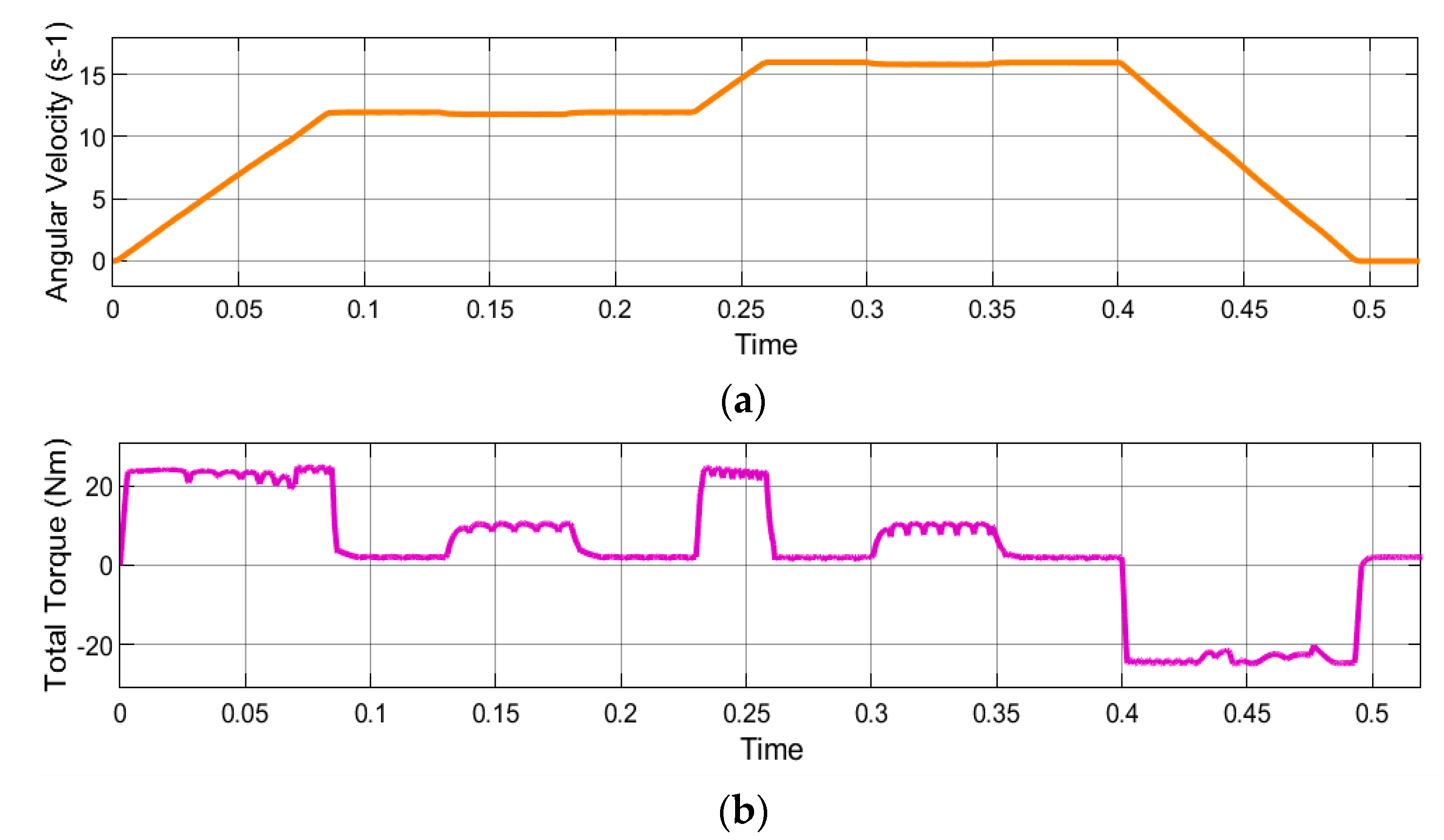
The performance of the test task by the DTP BLDCM is shown by the waveforms in Figure 12. Figure 12(a) shows the angular velocity, which changes with maximum acceleration provided by the maximum electromagnetic torque at a level of 25 Nˑm at the given moment of inertia of the drive. As can be seen from Figure 12(b), the electromagnetic torque ripples during two-module operation (in transient modes) are reduced by more than two times compared to single-module operation (in steady-state modes).
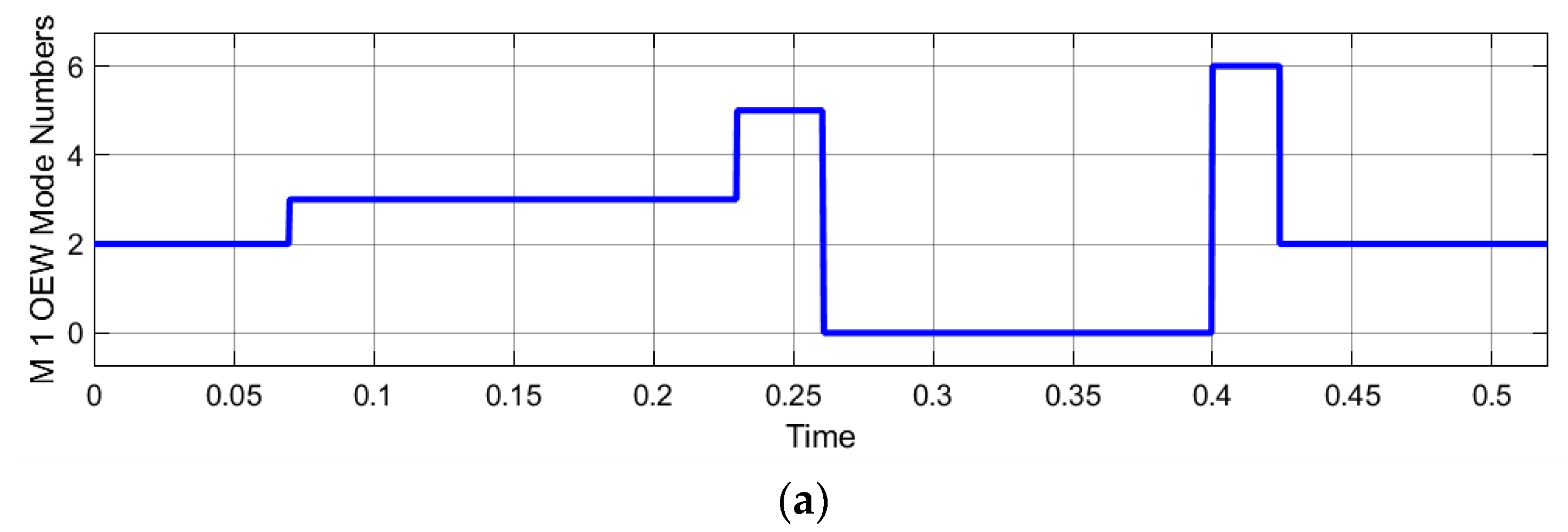
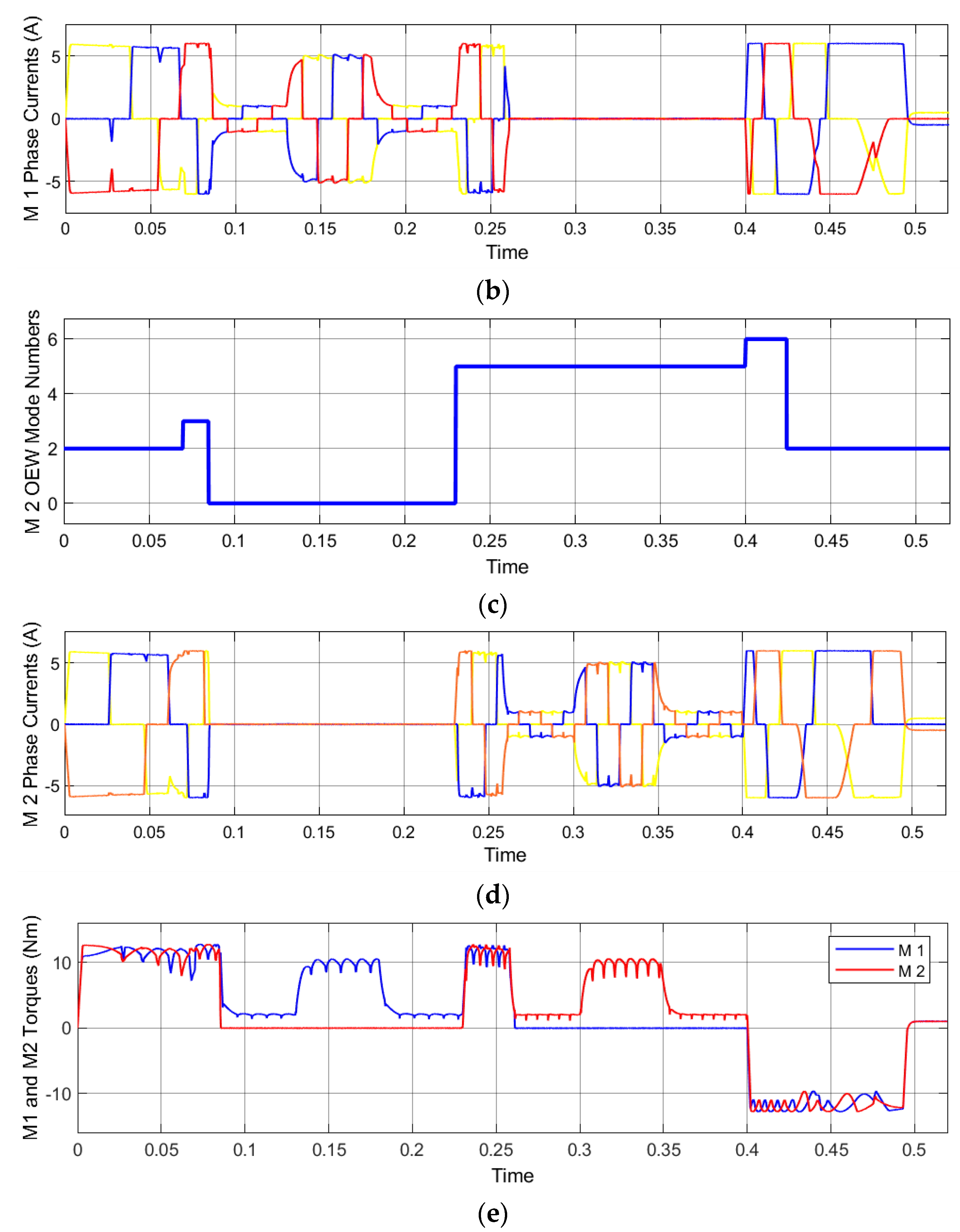
To test the operation of the developed EMS algorithm, it was specially specified that the SOCSCM reaches its minimum value at a time of 0.07 s, and then, according to the algorithm, the EMS operation is aimed at charging of the SCM. This can be observed from the waveforms of the OEW mode numbers for the modules M 1 (Figure 13(a)) and M 2 (Figure 13(c)), the phase currents of these modules shown in Figure 13(b) and Figure 13(d), respectively, as well as electromagnetic torques formed by each of the modules (Figure 13(e)).
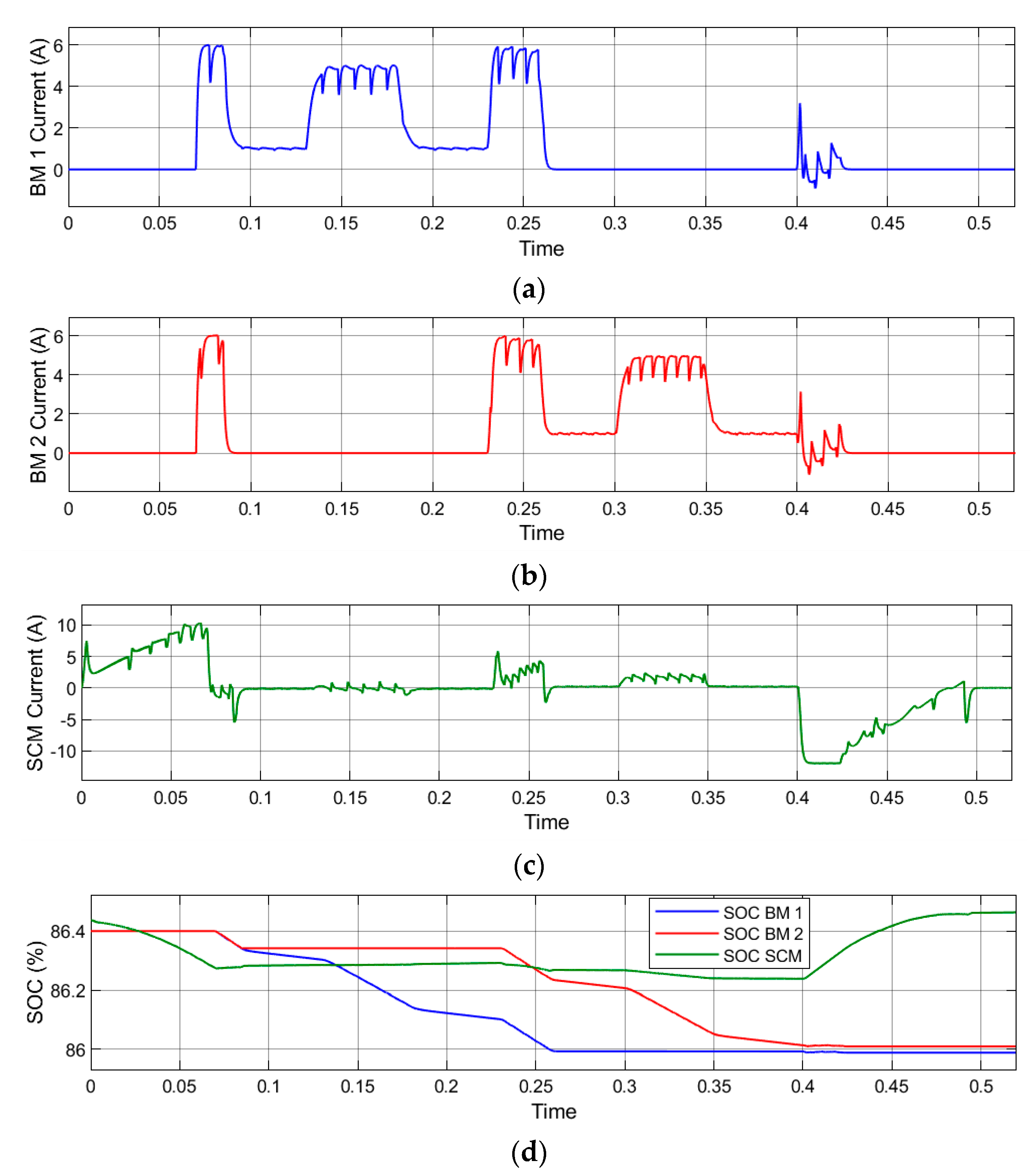
The initial acceleration of the motor in I zone was carried out by two machine modules powered by the SCM (mode 2 according to Table 4). From 0.07 s, the process of acceleration to the nominal angular velocity in I zone was already completed in mode 3, when the armature-winding modules were already powered by the BM 1 and BM 2, and the SCM was somewhat charged, however slightly, because the angular velocity was already high. This can be observed from the waveforms of DC currents of all power modules (Figure 14(a,b,c)) and the dynamics of their SOCs (Figure 14(d)). In the steady-state motion, under a light load of the drive, only the first module powered by its module BM 1 worked in I zone. During acceleration in II zone, from 0.23 s, two machine modules were already working again in mode 5, and at steady speed in this zone, the first module was shut down and only the second machine module was working. Two machine modules again provided the regenerative braking to a complete stop of the drive, which began at a time of 0.4 s. In II zone, the machine modules worked in mode 6, and then in I zone they worked in mode 2 according to Table. 6. Practically all the braking energy provided the SCM charging (Figure 15(c)). This brought its SOC back to the level it was at the beginning of the test simulation (Figure 15(d)). At the same time, the two battery modules discharged almost equally during the simulation (Figure 15(a,b)).

4.2. Results Discussion

The conducted test computer simulation covered most of the OEW mode numbers predicted by the developed EMS algorithm. In the modes that ensure discharge of the SCM in the cases when its SOC exceeds the maximum value, the test simulation also showed the effectiveness of the developed modes of operation. In such cases, the discharge of the SCM on one or two battery modules took place during the execution of the given parameters of movement and load of the drive.
The analysis of the obtained computer simulation results showed that at low BLDCM speeds, during its operation in I zone, it is possible to keep completely the SOCSCM in the given range. During the operation of the motor at high speeds, in II zone, during short-term operation, this task is also performed, especially when traction and braking modes of the drive operation alternate. In the cases of long-term operation of the BLDCM at high speeds, when the SCM is discharged for a long time, none of the provided by the EMS operating modes are able to keep the SOCSCM in the specified range.

5. Experimental Verification

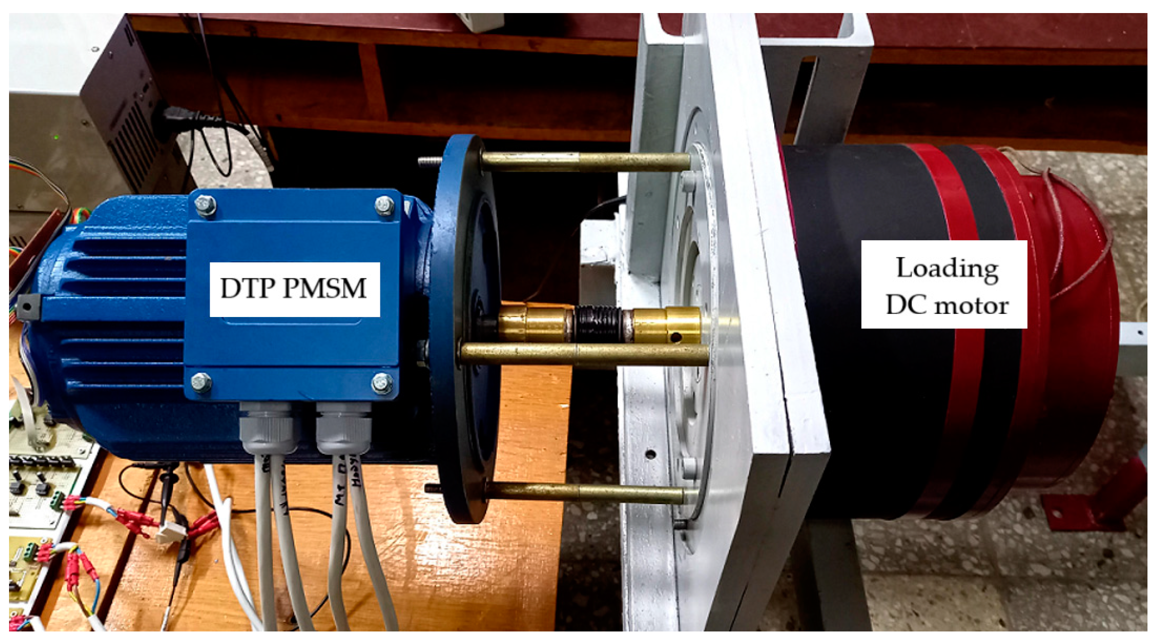
For the experimental study of the H–H configuration of the EV powertrain, the developed mock-up sample of DTP BLDCM drive with PMSM of an asymmetric configuration with an optimal displacement between the armature winding modules by 30o el. was used (Figure 15). Parameters of this DTP BLDCM drive are shown in Table 9. Two sensor systems of rotor position are mounted in the PMSM, each of which uses three Hall SS49E point sensors. A special multipole DC motor was used to load the experimental DTP BLDCM.
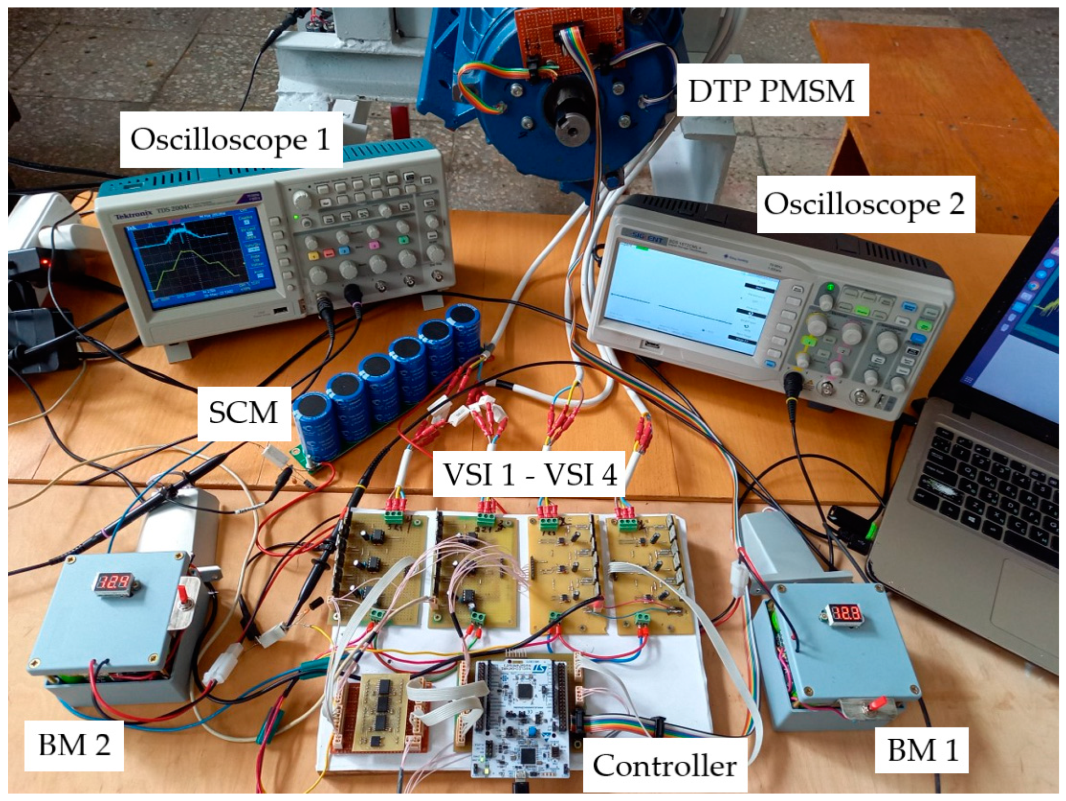
All experimental setup is shown in Figure 16. Each of the battery modules BM 1 and BM 2 consists of nine Westinghouse 26650 Li-Ion cells with a capacity of 4500 mAh connected according to the 3S3P scheme, and a BMS board HX-3S-FL25A-А. The SCM consists of six series-connected SCs with a capacity of 500 F and a nominal voltage of 2.7 V of the GDCPH type CH18124. Thus, the capacitance of the SCM was 500/6 = 83.3 F and its maximum voltage was 2.7‧6 = 16.2 V. The four VSIs are implemented on IRF3205 MOSFET switches with IR2104 drivers. The PWM operating frequency for controlling the inverters was 10 kHz. To evaluate and measure the shape of the currents, current measuring shunts with a resistance of 0.1 Ohm are connected to each of the phases of the armature windings, as well as to the power supply modules. Two digital oscilloscopes due to problems with common points carried out the recording of waveforms of the main variables.
The entire developed control algorithm of the experimental setup is implemented in the STM32G474RE microcontroller, which is placed on the Nucleo debugging board (Figure 16). The PWM control of the electric drive system was implemented using the STM32G4 microcontroller's advanced timers, which offer high-resolution PWM generation and dead-time insertion. A digital signal isolator board based on three ADUM1401 microchips was built. It was used for galvanic isolation of 12 signals to MOSFETs.
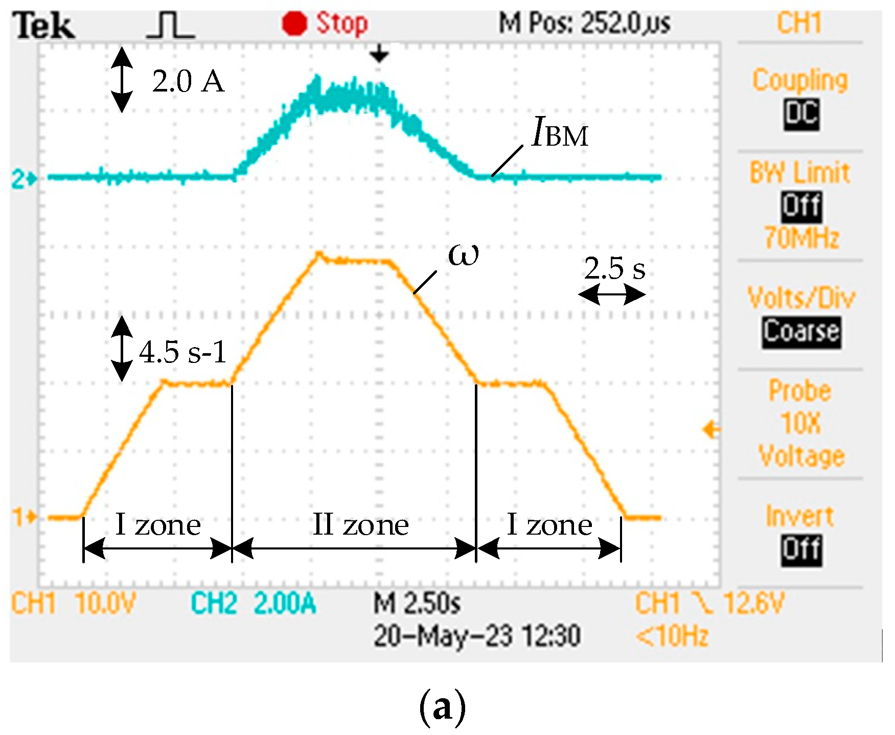
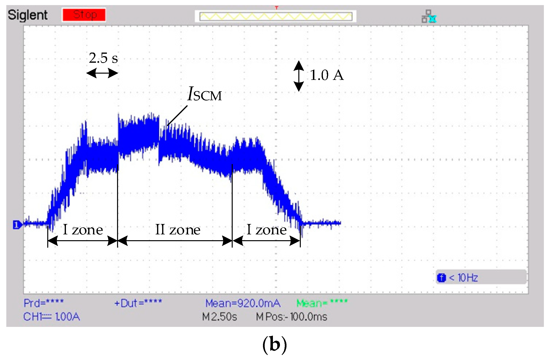
Figure 17 shows the waveforms obtained on the experimental setup of the powertrain under study. The experimental movement tachogram was formed as follows. Initially, the motor accelerated with a given acceleration of 3.0 s-1 in I zone of its speed regulation (Figure 17(a)). At the same time, two machine modules operated, receiving power from the SCM (Figure 17(b)). After reaching the nominal speed for zone I, the motor rotated with a constant angular velocity during 2.5 s. Here, one motor module was already running, receiving power from the SCM, whose SOC remained high. Next, the task of increasing the angular velocity was came, and the motor accelerated with the same acceleration already in II zone and then rotated with a constant maximum speed during 2.5 s (Figure 17(a)). At the same time, one machine module was working, but with two-way power supply, as can be seen from the waveform of the BM 1 current (Figure 17(a)). Next, the motor speed decreased first in II zone, and then in I zone, but without electrical braking, which is caused by a rather large reactive torque of the static load, which was created by the loading machine on the shaft of the experimental motor.

6. Conclusions

The analysis of the latest research, as well as the results of our own work, give grounds for concluding that the modular approach to EV powertrain construction is promising due to its various advantages compared to classic configurations. These advantages manifested b increase of energy efficiency, fault tolerance, overall reliability, safety, and advanced control capabilities. The best results are achieved in the case of combining modules of sources of on-board power systems, in particular hybrid ones, with modules of electric machines due to the use of power semiconductor converters of various topologies with an increased number of degrees of freedom. The redundancy of the control channels of the latter makes it possible to significantly expand their functionality and implement multi-purpose management of their work, for example, performance of functions of energy management of power sources, control of the vehicle in the event of failures, etc.
The proposed H–H EV powertrain configuration based on DTP BLDCM with two machine modules of asymmetric configuration and the connection of their winding sets according to the OEW principle, as well as a hybrid B-SC modular electric power supply system has wide possibilities for providing different modes of operation of machine modules with different options for their power supply. These possibilities are implemented in the developed OEW machine module modes for EV traction and braking system. Based on this system, the EMS algorithm was developed, which makes it possible to combine the implementation of the required operating modes of the drive with the simultaneous performance of the functions of maintaining the required SOC level of the SCM and equalizing the SOCs of the two battery modules.
Simulation studies of the H–H configuration of the EV powertrain based on the DTP BLDCM confirmed the effectiveness of the proposed solutions regarding the implementation of the OEW machine module modes system, as well as the effectiveness of the developed EMS function of maintaining the SOCSCM in the given range. This function works well during drive operation in zone I, at low EV speeds, but is limited in zone II during drive operation at high speeds, when there is no possibility of recharging the SCM. Therefore, in further research, it is necessary to find additional solutions to ensure the long-term operation of EVs at high speeds.
Conducted experimental studies on the created setup confirmed the operability of the proposed H–H EV powertrain configuration, implemented based on the created DTP BLDCM samples and power supply modules.

Author Contributions

Conceptualization, I.S.; methodology, I.S. and V.T.; software, V.T.; validation, V.T., formal analysis, I.S. and V.T.; investigation, I.S. and V.T.; resources, I.S.; data curation, V.T.; writing—original draft preparation, I.S. and V.T.; writing—review and editing, I.S.; visualization, V.T.; supervision, I.S.; project administration, I.S.; funding acquisition, I.S.

Funding

This research was funded by Ministry of Education and Science of Ukraine, grant number 0120U102206.

Conflicts of Interest

The authors declare no conflict of interest.

References

  1. Skouras, T.; Gkonis, P.; Ilias, C.; Trakadas, P.; Tsampasis, E.; Zahariadis, T. Electrical vehicles: current state of the art, future challenges, and perspectives. Clean Technol. 2019, 2 (1), 1–16. https://doi.org/10.3390/cleantechnol2010001. [CrossRef]
  2. Stippich, A. Key components of modular propulsion systems for next generation electric vehicles. CPSS Trans. Power Electron. Appl. 2017, 2 (4), 249–258. https://doi.org/10.24295/CPSSTPEA.2017.00023. [CrossRef]
  3. Un-Noor, F.; Padmanaban, S.; Mihet-Popa, L.; Mollah, M.; Hossain, E. A comprehensive study of key electric vehicle (EV) components, technologies, challenges, impacts, and future direction of development. Energies 2017, 10 (8), 1217. https://doi.org/10.3390/en10081217. [CrossRef]
  4. Kuznetsov, B.; Bovdui, I.; Nikitina, T.; Kolomiets, V.; Kobilyanskiy, B. Multi-motor plant related electric drives robust control synthesis. In Proceedings of the 2020 IEEE 4th International Conference on Intelligent Energy and Power Systems (IEPS); IEEE: Istanbul, Turkey, 2020; pp 242–245. https://doi.org/10.1109/IEPS51250.2020.9263169. [CrossRef]
  5. Hemsen, J.; Kieninger, D.; Eckstein, L.; Lidberg, M. R.; Huisman, H.; Arrozy, J.; Lomonova, E. A.; Oeschger, D.; Lanneluc, C.; Tosoni, O.; Debal, P.; Ernstorfer, M.; Mongellaz, R. Innovative and highly integrated modular electric drivetrain. World Electr. Veh. J. 2019, 10 (4), 89. https://doi.org/10.3390/wevj10040089. [CrossRef]
  6. Mahmoudzadeh Andwari, A.; Pesiridis, A.; Rajoo, S.; Martinez-Botas, R.; Esfahanian, V. A Review of battery electric vehicle technology and readiness levels. Renew. Sustain. Energy Rev. 2017, 78, 414–430. https://doi.org/10.1016/j.rser.2017.03.138. [CrossRef]
  7. Hemmati, R.; Saboori, H. Emergence of hybrid energy storage systems in renewable energy and transport applications – A Review. Renew. Sustain. Energy Rev. 2016, 65, 11–23. https://doi.org/10.1016/j.rser.2016.06.029. [CrossRef]
  8. Kouchachvili, L.; Yaïci, W.; Entchev, E. Hybrid battery/supercapacitor energy storage system for the electric vehicles. J. Power Sources 2018, 374, 237–248. https://doi.org/10.1016/j.jpowsour.2017.11.040. [CrossRef]
  9. Benmouna, A.; Becherif, M.; Chen, J.; Chen, H.; Depernet, D. Interconnection and damping assignment passivity based control for fuel cell and battery vehicle: simulation and experimentation. Int. J. Hydrog. Energy 2019, 44 (39), 22467–22477. https://doi.org/10.1016/j.ijhydene.2019.02.045. [CrossRef]
  10. Yang, B.; Zhu, T.; Zhang, X.; Wang, J.; Shu, H.; Li, S.; He, T.; Yang, L.; Yu, T. Design and implementation of battery/smes hybrid energy storage systems used in electric vehicles: a nonlinear robust fractional-order control approach. Energy 2020, 191, 116510. https://doi.org/10.1016/j.energy.2019.116510. [CrossRef]
  11. Paul, T.; Mesbahi, T.; Durand, S.; Flieller, D.; Uhring, W. Sizing of lithium-ion battery/supercapacitor hybrid energy storage system for forklift vehicle. Energies 2020, 13 (17), 4518. https://doi.org/10.3390/en13174518. [CrossRef]
  12. Yang, B.; Wang, J.; Zhang, X.; Wang, J.; Shu, H.; Li, S.; He, T.; Lan, C.; Yu, T. Applications of battery/supercapacitor hybrid energy storage systems for electric vehicles using perturbation observer based robust control. J. Power Sources 2020, 448, 227444. https://doi.org/10.1016/j.jpowsour.2019.227444. [CrossRef]
  13. Ostroverkhov, M.; Trinchuk, D. Increasing the efficiency of electric vehicle drives with supercapacitors in power supply. In Proceedings of the 2020 IEEE 7th International Conference on Energy Smart Systems (ESS); IEEE: Kyiv, Ukraine, 2020; pp 258–261. https://doi.org/10.1109/ESS50319.2020.9160291. [CrossRef]
  14. Berrueta, A.; Ursua, A.; Martin, I. S.; Eftekhari, A.; Sanchis, P. Supercapacitors: electrical characteristics, modeling, applications, and future trends. IEEE Access 2019, 7, 50869–50896. https://doi.org/10.1109/ACCESS.2019.2908558. [CrossRef]
  15. Wang, Y.; Yang, Z.; Li, F. Optimization of energy management strategy and sizing in hybrid storage system for tram. Energies 2018, 11 (4), 752. https://doi.org/10.3390/en11040752. [CrossRef]
  16. Hannan, M. A.; Hoque, Md. M.; Hussain, A.; Yusof, Y.; Ker, P. J. State-of-the-art and energy management system of lithium-ion batteries in electric vehicle applications: issues and recommendations. IEEE Access 2018, 6, 19362–19378. https://doi.org/10.1109/ACCESS.2018.2817655. [CrossRef]
  17. Jagadeesh, I.; Indragandhi, V. Review and comparative analysis on dc-dc converters used in electric vehicle applications. IOP Conf. Ser. Mater. Sci. Eng. 2019, 623 (1), 012005. https://doi.org/10.1088/1757-899X/623/1/012005. [CrossRef]
  18. Shchur, I.; Bilyakovskyy, I.; Turkovskyi, V. Improvement of switched structure semi-active battery/supercapacitor hybrid energy storage system for electric vehicles. IET Electr. Syst. Transp. 2021, 11 (3), 241–255. https://doi.org/10.1049/els2.12017. [CrossRef]
  19. Zhaohui, S.; Dongchang, Q.; Mian, W.; Guozhu, C. Study of modular cascaded dc-dc converter with interleaved control for energy storage system. In Proceedings of the 2015 IEEE 24th International Symposium on Industrial Electronics (ISIE); IEEE: Buzios, Rio de Janeiro, Brazil, 2015; pp 417–421. https://doi.org/10.1109/ISIE.2015.7281504. [CrossRef]
  20. Al Mashhadany, Y. I. High-Performance Multilevel Inverter Drive of Brushless DC Motor. Int J Sustain. Green Energy 2015, 4 (3–1), 1–7. https://doi.org/10.11648/j.ijrse.s.2015040301.11. [CrossRef]
  21. Lee, Y.; Ha, J.-I. Hybrid modulation of dual inverter for open-end permanent magnet synchronous motor. IEEE Trans. Power Electron. 2015, 30 (6), 3286–3299. https://doi.org/10.1109/TPEL.2014.2325738. [CrossRef]
  22. Loncarski, J.; Leijon, M.; Srndovic, M.; Rossi, C.; Grandi, G. Comparison of output current ripple in single and dual three-phase inverters for electric vehicle motor drives. Energies 2015, 8 (5), 3832–3848. https://doi.org/10.3390/en8053832. [CrossRef]
  23. Jia, Y.-F.; Chu, L.; Xu, N.; Li, Y.-K.; Zhao, D.; Tang, X. Power sharing and voltage vector distribution model of a dual inverter open-end winding motor drive system for electric vehicles. Appl. Sci. 2018, 8 (2), 254. https://doi.org/10.3390/app8020254. [CrossRef]
  24. Sandulescu, P.; Meinguet, F.; Kestelyn, X.; Semail, E.; Bruyere, A. Control strategies for open-end winding drives operating in the flux-weakening region. IEEE Trans. Power Electron. 2014, 29 (9), 4829–4842. https://doi.org/10.1109/TPEL.2013.2283107. [CrossRef]
  25. Lu, S.; Corzine, K. A.; Ferdowsi, M. A Unique ultracapacitor direct integration scheme in multilevel motor drives for large vehicle propulsion. IEEE Trans. Veh. Technol. 2007, 56 (4), 1506–1515. https://doi.org/10.1109/TVT.2007.896970. [CrossRef]
  26. Vilathgamuwa, D. M.; Jayasinghe, S. D. G.; Lee, F. C.; Madawala, U. K. A Unique battery/supercapacitor direct integration scheme for hybrid electric vehicles. In In Proceedings of the IECON 2011 - 37th Annual Conference of the IEEE Industrial Electronics Society; IEEE: Melbourne, Vic, Australia, 2011; pp 3020–3025. https://doi.org/10.1109/IECON.2011.6119791. [CrossRef]
  27. Jayasinghe, S. D. G.; Vilathgamuwa, D. M.; Madawala, U. K. A Dual inverter based supercapacitor direct integration scheme for wind energy conversion systems. In Proceedings of the 2010 IEEE International Conference on Sustainable Energy Technologies (ICSET); IEEE: Kandy, Sri Lanka, 2010; pp 1–6. https://doi.org/10.1109/ICSET.2010.5684459. [CrossRef]
  28. Barrero, F.; Duran, M. J. Recent advances in the design, modeling, and control of multiphase machines—part i. IEEE Trans. Ind. Electron. 2016, 63 (1), 449–458. https://doi.org/10.1109/TIE.2015.2447733. [CrossRef]
  29. Negahdari, A.; Yepes, A. G.; Doval-Gandoy, J.; Toliyat, H. A. Efficiency enhancement of multiphase electric drives at light-load operation considering both converter and stator copper losses. IEEE Trans. Power Electron. 2019, 34 (2), 1518–1525. https://doi.org/10.1109/TPEL.2018.2830310. [CrossRef]
  30. Patel, V. I.; Wang, J.; Nugraha, D. T.; Vuletic, R.; Tousen, J. Enhanced availability of drivetrain through novel multiphase permanent-magnet machine drive. IEEE Trans. Ind. Electron. 2016, 63 (1), 469–480. https://doi.org/10.1109/TIE.2015.2435371. [CrossRef]
  31. Shchur, I.; Jancarczyk, D. Electromagnetic torque ripple in multiple three-phase brushless DC motors for electric vehicles. Electronics 2021, 10 (24), 3097. https://doi.org/10.3390/electronics10243097. [CrossRef]
  32. Salem, A.; Narimani, M. A review on multiphase drives for automotive traction applications. IEEE Trans. Transp. Electrification 2019, 5 (4), 1329–1348. https://doi.org/10.1109/TTE.2019.2956355. [CrossRef]
  33. Fu, Z.; Liu, J.; Xing, Z. Performance analysis of dual-redundancy brushless DC motor. Energy Rep. 2020, 6, 829–833. https://doi.org/10.1016/j.egyr.2020.11.125. [CrossRef]
  34. Bogusz, P.; Korkosz, M.; Prokop, J. A study of dual-channel brushless DC motor with permanent magnets. In Proceedings of the 2016 13th Selected Issues of Electrical Engineering and Electronics (WZEE); IEEE: Rzeszow, Poland, 2016; pp 1–6. https://doi.org/10.1109/WZEE.2016.7800189. [CrossRef]
  35. Shchur, I.; Turkovskyi, V. Comparative study of brushless DC motor drives with different configurations of modular multilevel cascaded converters. In Proceedings of the 2020 IEEE 15th International Conference on Advanced Trends in Radioelectronics, Telecommunications and Computer Engineering (TCSET); IEEE: Lviv-Slavske, Ukraine, 2020; pp 447–451. https://doi.org/10.1109/TCSET49122.2020.235473. [CrossRef]
  36. Shchur, I.; Turkovskyi, V. Multilevel DC link inverter fed BLDC motor drive with modular battery/supercapacitor HESS for electric vehicle. In Proceedings of the 2020 IEEE Problems of Automated Electrodrive. Theory and Practice (PAEP); IEEE: Kremenchuk, Ukraine, 2020; pp 1–6. https://doi.org/10.1109/PAEP49887.2020.9240871. [CrossRef]
  37. Shchur, I. Z.; Turkovskyi, V. P. Integrated system of modular power supply and multilevel control of brushless DC motor for electric vehicles. Nauk. Visnyk Natsionalnoho Hirnychoho Universytetu 2020, 6, 68–75. https://doi.org/10.33271/nvngu/2020-6/068. [CrossRef]
  38. Shchur, I.; Turkovskyi, V.; Boichuk, B. Dual battery powered drive system using an open-end winding brushless DC motor. In Proceedings of the 2021 IEEE 3rd Ukraine Conference on Electrical and Computer Engineering (UKRCON); IEEE: Lviv, Ukraine, 2021; pp 327–332. https://doi.org/10.1109/UKRCON53503.2021.9575807. [CrossRef]
  39. Shchur, I.; Turkovskyi, V. Open-end winding dual three-phase BLDC motor drive system with integrated hybrid battery-supercapacitor energy storage for electric vehicle. In Proceedings of the 2021 IEEE International Conference on Modern Electrical and Energy Systems (MEES); IEEE: Kremenchuk, Ukraine, 2021; pp 1–6. https://doi.org/10.1109/MEES52427.2021.9598697. [CrossRef]
  40. Makarchuk, O.; Kharchyshyn, B.; Kasha, L. Analysis of the magneto-mechanical characteristic of double three-phase PMSM. In Proceedings of the 2021 IEEE 3rd Ukraine Conference on Electrical and Computer Engineering (UKRCON); IEEE: Lviv, Ukraine, 2021; pp 333–338. https://doi.org/10.1109/UKRCON53503.2021.9575684. [CrossRef]
  41. Shchur, I.; Mazur, D.; Makarchuk, O.; Bilyakovskyy, I.; Turkovskyi, V.; Kwiatkowski, B.; Kalandyk, D. Improved Matlab/Simulink model of dual three-phase fractional slot and concentrated winding PM motor for EV applied brushless DC drive. Archives of Control Sciences 2022, 32 (4), 677–707. https://doi.org/10.24425/acs.2022.143667. [CrossRef]
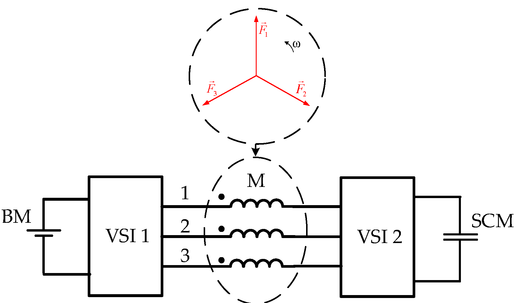
Figure 1. Hybrid B-SC dual inverter-fed OEW BLDCM configuration.
Preprints 74949 g001
Figure 2. Hybrid B-SC triple inverter-fed T configuration with DTP BLDCM of symmetrical winding sets.
Preprints 74949 g002
Figure 3. Hybrid B-SC quadruple inverter-fed H-H configuration with DTP BLDCM of asymmetrical winding sets.
Preprints 74949 g003
Figure 4. General scheme of the proposed H–H configuration of the modular powertrain.
Preprints 74949 g004
Figure 5. Block diagram of the general algorithm for controlling the DTP BLDCM operating modes and EMS.
Preprints 74949 g005
Figure 6. Fragments of the block diagram of the general control algorithm and EMS for cases of EV traction mode when the DTP BLDCM operates in I zone under light load.
Preprints 74949 g006
Figure 7. Three-position control of SCM charging-discharging processes with hysteresis.
Preprints 74949 g007
Figure 8. Fragments of the block diagram of the general control algorithm and EMS for the EV traction mode and the cases when the DTP BLDCM operates in I zone under heavy load (a) and in II zone (b).
Preprints 74949 g008aPreprints 74949 g008b
Figure 9. Fragments of the block diagram of the general control algorithm and EMS for the EV braking mode and the cases when the DTP BLDCM operates in I zone under light load (a), in I zone under heavy load (b), and in II zone (c).
Preprints 74949 g009
Figure 10. The main fragment of the computer model proposed H–H powertrain configuration with DTP BLDСM.
Preprints 74949 g010
Figure 11. Reference angular velocity (a) and load torque (b).
Preprints 74949 g011aPreprints 74949 g011b
Figure 12. Actual angular velocity (a) and torque (b) of DTP BLDCM.
Preprints 74949 g012
Figure 13. Results of the machine modules operation: OEW mode numbers (a) and phase currents (b) of the module M 1, OEW mode numbers (c) and phase currents (d) of the module M 2, electromagnetic torques of the modules M 1 and M 2 (e).
Preprints 74949 g013aPreprints 74949 g013b
Figure 14. DC currents of the power supply modules BM 1 (a), BM 2 (b), SCM (c) and their SOCs (d).
Preprints 74949 g014
Figure 15. Electromechanical stand for studying modular powertrain.
Preprints 74949 g015
Figure 16. Experimental setup.
Preprints 74949 g016
Figure 17. Obtained waveforms of motor angular velocity and BM 1 current (a) and SCM current (b) in one machine module.
Preprints 74949 g017aPreprints 74949 g017b
Table 1. The order of six-step switching of the BLDC drive based on the DTP PM machine of asymmetrical configuration with the offset of the armature-winding sets by 30o el. for the VSI 1 and VSI 2 (traction mode of operation).
θ(° el.) Switching states θ(° el.)
VSI 1 VSI 2
S11 S21 S31 S41 S51 S61 S12 S22 S32 S42 S52 S62
0–30 1 1 0 0 0 0 1 1 0 0 0 0 0–30
30–60 1 0 0 1 0 0 30–60
60–90 1 0 0 1 0 0 60–90
90–120 0 0 1 1 0 0 90–120
120–150 0 0 1 1 0 0 120–150
150–180 0 0 1 0 0 1 150–180
180–210 0 0 1 0 0 1 180–210
210–240 0 0 0 0 1 1 210–240
240–270 0 0 0 0 1 1 240–270
270–300 0 1 0 0 1 0 270–300
300–330 0 1 0 0 1 0 300–330
330–360 1 1 0 0 0 0 330–360
Table 2. The order of six-step switching of the BLDC drive based on the DTP PM machine of asymmetrical configuration with the offset of the armature-winding sets by 30o el. for the VSI 3 and VSI 4 (traction mode of operation).
θ(° el.) Switching states θ(° el.)
VSI 3 VSI 4
S13 S23 S33 S43 S53 S63 S14 S24 S34 S44 S54 S64
0–30 0 0 1 0 0 1 0 0 1 0 0 1 0–30
30–60 0 0 0 0 1 1 30–60
60–90 0 0 0 0 1 1 60–90
90–120 0 1 0 0 1 0 90–120
120–150 0 1 0 0 1 0 120–150
150–180 1 1 0 0 0 0 150–180
180–210 1 1 0 0 0 0 180–210
210–240 1 0 0 1 0 0 210–240
240–270 1 0 0 1 0 0 240–270
270–300 0 0 1 1 0 0 270–300
300–330 0 0 1 1 0 0 300–330
330–360 0 0 1 0 0 1 330–360
Table 3. Switches states in different VSI operation modes.
Switches Inverter Operation Modes
1 2 3 4
S1 0 1 (0) Switching according to the 120-degree conductivity with voltage regulation Switching according to the 120-degree conductivity without voltage regulation
S3 0 1 (0)
S5 0 1 (0)
S2 0 0 (1)
S4 0 0 (1)
S6 0 0 (1)
Table 4. Operation modes of the machine modules with dual-inverter power supply of their open ends during EV traction.
Machine modules M 1 (М 2) OEW machine module mode number
0 1 2 3 4 5 6
VSI 1
(VSI 2)
mode 1 3 2 4 -3 4 3
iDC iDC = 0 iDC > 0 iDC = 0 iDC > 0 iDC < 0 iDC > 0 iDC > 0
VSI 3
(VSI 4)
mode 1 2 3 -3 4 3 4
iDC iDC = 0 iDC = 0 iDC > 0 iDC < 0 iDC > 0 iDC > 0 iDC > 0
Zone of operation I zone I zone I zone I zone I zone II zone II zone
Table 5. Modes of operation of the BM and SCM at the different OEW module modes during EV traction.
OEW module mode number Modes of operation of the BM and SCM
1 BM feeds the motor module
2 SCM feeds the motor module
3 BM feeds the motor module and charges the SCM
4 SCM feeds the motor module and charges the BM
5 BM and SCM feed the motor module (iBM > iSCM)
6 BM and SCM feed the motor module (iBM < iSCM)
Table 6. Operation modes of the machine modules with dual-inverter power supply of their open ends during EV breaking.
Machine modules M 1 (М 2) OEW machine module mode number
0 1 2 3 4 5 6
VSI 1
(VSI 2)
mode 1 -3 2 -4 3 -4 -3
iDC iDC = 0 iDC < 0 iDC = 0 iDC < 0 iDC > 0 iDC < 0 iDC < 0
VSI 3
(VSI 4)
mode 1 2 -3 3 -4 -3 -4
iDC iDC = 0 iDC = 0 iDC < 0 iDC > 0 iDC < 0 iDC < 0 iDC < 0
Zone of operation I zone I zone I zone I zone I zone II zone II zone
Table 7. Modes of operation of the BM and SCM at the different OEW module modes during EV braking.
OEW module mode number Modes of operation of the BM and SCM
1 BM receives the motor module braking energy
2 SCM receives the motor module braking energy
3 BM receives the motor module braking energy and discharge energy of the SCM
4 SCM receives the motor module braking energy and discharge energy of the BM
5 BM and SCM receive the motor module braking energy (|iBM| > |iSCM|)
6 BM and SCM receive the motor module braking energy (|iBM| < |iSCM|)
Table 8. Parameters of the studied DTP BLDC drives.
Parameter Value
Rated DC voltage for one module (V) 24
Rated torque (Nm) 10
Rated angular velocity (s-1) 24
Number pair of poles 10
Moment of inertia (kg‧m2) 0.15
Phase winding resistance (Ω) 0.250
Phase winding self-inductance (mH) 5.39
Winding mutual inductance (mH) 1.59
Flux linkage by PM (Wb) 0.112
Table 9. Parameters of the experimental DTP PMSM.
Parameter Value
Rated power (W) 350
Rated DC voltage for one module (V) 24
Rated phase rms current (A) 7.4
Rated torque (Nm) 20
Rated angular speed (rpm) 165
Number pair of poles 17
Moment of inertia (kg‧m2) 0.15
Disclaimer/Publisher’s Note: The statements, opinions and data contained in all publications are solely those of the individual author(s) and contributor(s) and not of MDPI and/or the editor(s). MDPI and/or the editor(s) disclaim responsibility for any injury to people or property resulting from any ideas, methods, instructions or products referred to in the content.
Copyright: This open access article is published under a Creative Commons CC BY 4.0 license, which permit the free download, distribution, and reuse, provided that the author and preprint are cited in any reuse.
Prerpints.org logo

Preprints.org is a free preprint server supported by MDPI in Basel, Switzerland.

Subscribe

© 2024 MDPI (Basel, Switzerland) unless otherwise stated