Submitted:
12 June 2023
Posted:
12 June 2023
You are already at the latest version
Abstract
Keywords:
1. Introduction
2. Materials and methods
2.1. Governing equations of the plate


2.2. Rectangular isotropic plate clamped along two opposite edges
2.2.1. Primary problem: plate simply supported along two opposite edges
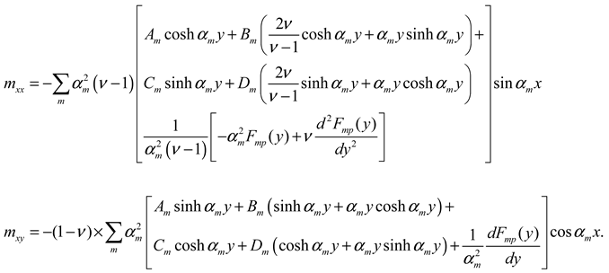
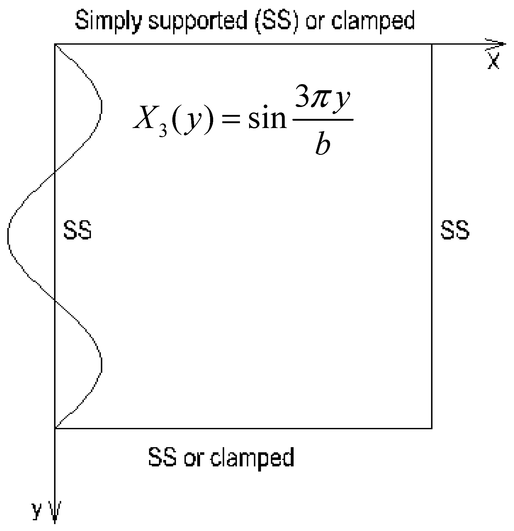
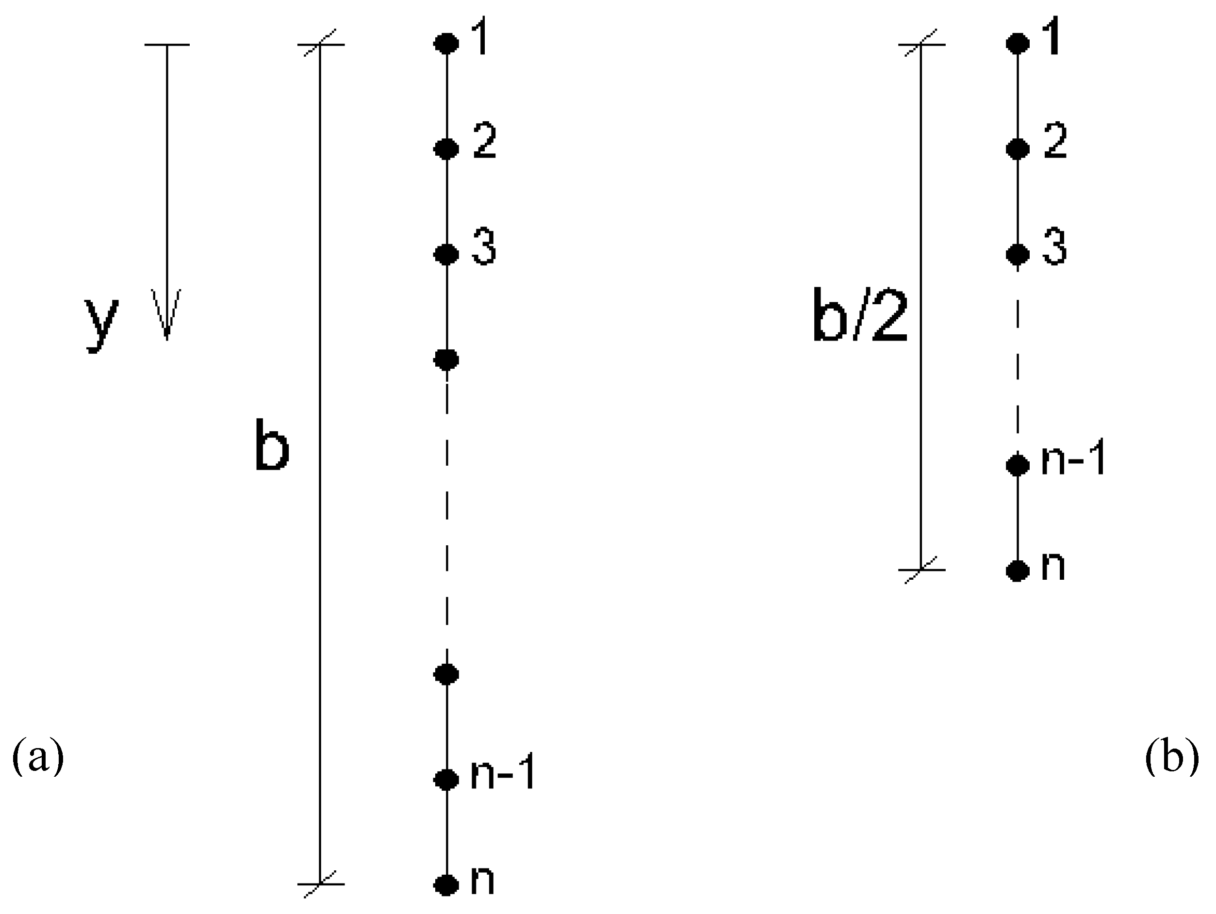
2.2.2. Redundant problem: plate subjected to a distributed bending moment along the edge x = 0
2.2.2.1. Edges y = 0 and y = b simply supported or clamped
- Redundant problem Xi = 1

2.2.2.2. Edge y = 0 simply supported or clamped, and edge y = b free
- Redundant problem Xi = 1
2.2.2.3. Edges y = 0 and y = b free
- Redundant problem Xi = 1
2.2.3. Redundant problem: plate subjected to a distributed bending moment along the edge x = a
3. Results and discussion
3.1. Plate clamped along the edges x = 0, y = 0, and y = b and simply supported along x = a
3.2. Rectangular plate clamped along all edges
3.3. Rectangular plate clamped along x = 0, simply supported along x = a and y = 0, and free along y = b
3.4. Rectangular plate clamped along the edges x = 0 and x = a, free along the edges y = 0 and y = b and subjected to an anti-symmetrical loading
4. Conclusions
Supplementary Materials
- “Rectangular plate clamped and simply supported”
- “Rectangular plate clamped along all edges”
- “Rectangular plate clamped simply supported and free”
- “Rectangular plate clamped and free.”
Conflicts of Interest
References
- Kirchhoff, G. Über das Gleichgewicht und die Bewegung einer elastischen Scheibe. J. für die Reine und Angew. Math.; vol. 18, no. 40, pp. 51-88, 1850. [CrossRef]
- Germain, S. Remarques sur la nature, les bornes et l’étendue de la question des surfaces élastiques et équation générale de ces surfaces. impr. de Huzard-Courcier, paris, 1826.
- Navier, C.L. Extrait des recherches sur la flexion des plaques élastiques. Bull. des Sci. Société Philomath, Paris, vol. 10, no. 1, pp. 92–102, 1823.
- Lévy, M. Sur l’équilibre élastique d’une plaque rectangulaire. Comptes rendus l’Académie des Sci. Paris, vol. 129, no. 1, pp. 535-539, 1899.
- Timoshenko, S., Woinowsky-Krieger, S. Theory of plates and shells. Second ed., McGraw Hill, New York (1959).
- Mama, B.O., Oguaghamba, O.A., Ike, C.C. Single Finite Fourier Sine Integral Transform Method for the Flexural Analysis of Rectangular Kirchhoff Plate with Opposite Edges Simply Supported, Other Edges Clamped for the Case of Triangular Load Distribution. IJERT, Vol. 13, 7 (2020), pp. 1802-1813. [CrossRef]
- Sayyad, A.S., Ghugal Y.M. Bending of shear deformable plates resting on Winkler foundations according to trigonometric plate theory. J. Appl. Comput. Mech., 4(3) (2018) 187-201. [CrossRef]
- Xu, Y., Wu, Zhangjan. Exact solutions for rectangular anisotropic plates with four clamped edges. Mechanics of Advanced Materials and Structures, Volume 29, 2022 - Issue 12. [CrossRef]
- Khan, Y., Tiwari, P., Ali, R. Application of variational methods to a rectangular clamped plate problem. Computers & Mathematics with Applications. Volume 63, Issue 4, February 2012, Pages 862-869. [CrossRef]
- Onyia, M.E., Rowland-Lato, E.O., Ike, C.C. Elastic buckling analysis of SSCF and SSSS rectangular thin plates using the single finite Fourier sine integral transform method. IJERT, Vol 13, No 6, pp 1147 – 1158, july 2020. [CrossRef]
- Pisacic, K., Horvat, M., Botak, Z. Finite Difference Solution of Plate Bending Using Wolfram Mathematica. Tehnicki Glasnik 13, 3(2019), 241-247. [CrossRef]
- Delyavskyy, M., Rosinski, K. The New Approach to Analysis of Thin Isotropic Symmetrical Plates. Appl. Sci. 2020, 10, 5931. [CrossRef]
- Imrak, C.E., Gerdemeli, I. An Exact Solution for the Deflection of a Clamped Rectangular Plate under Uniform Load. Applied Mathematical Sciences, Vol. 1, 2007, no. 43, 2129 - 2137.
- Czerny, F. Tafeln für vierseitig und dreiseitig gelagerte Rechteckplatten (Tables for rectangular plates supported along four and along three edges). Beton-Kalender 1982, Teil 1. Verlag Von Wilhelm, Ernst & Sohn Berlin, München S. 397-474. In German.
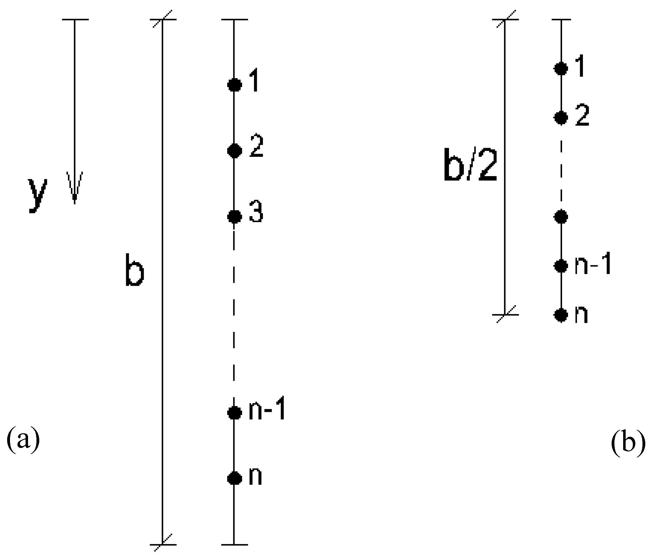
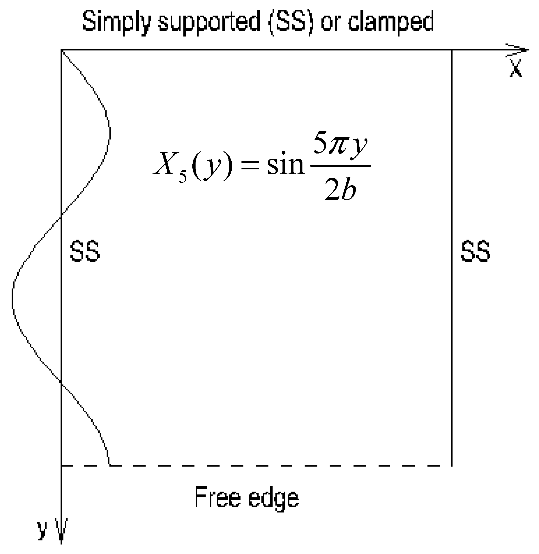
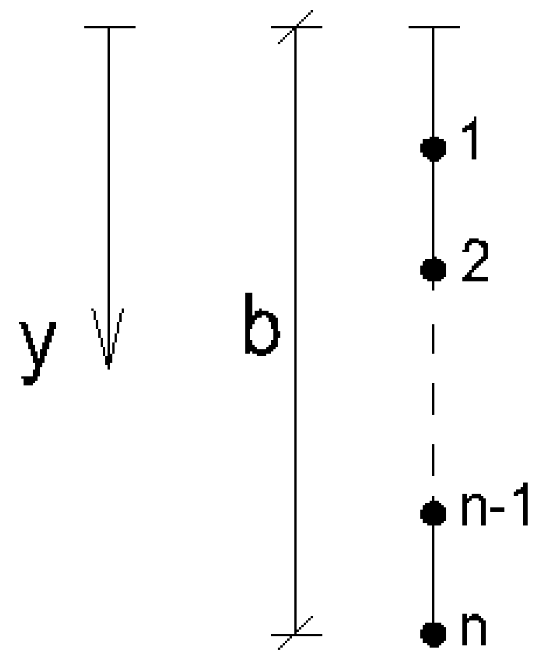
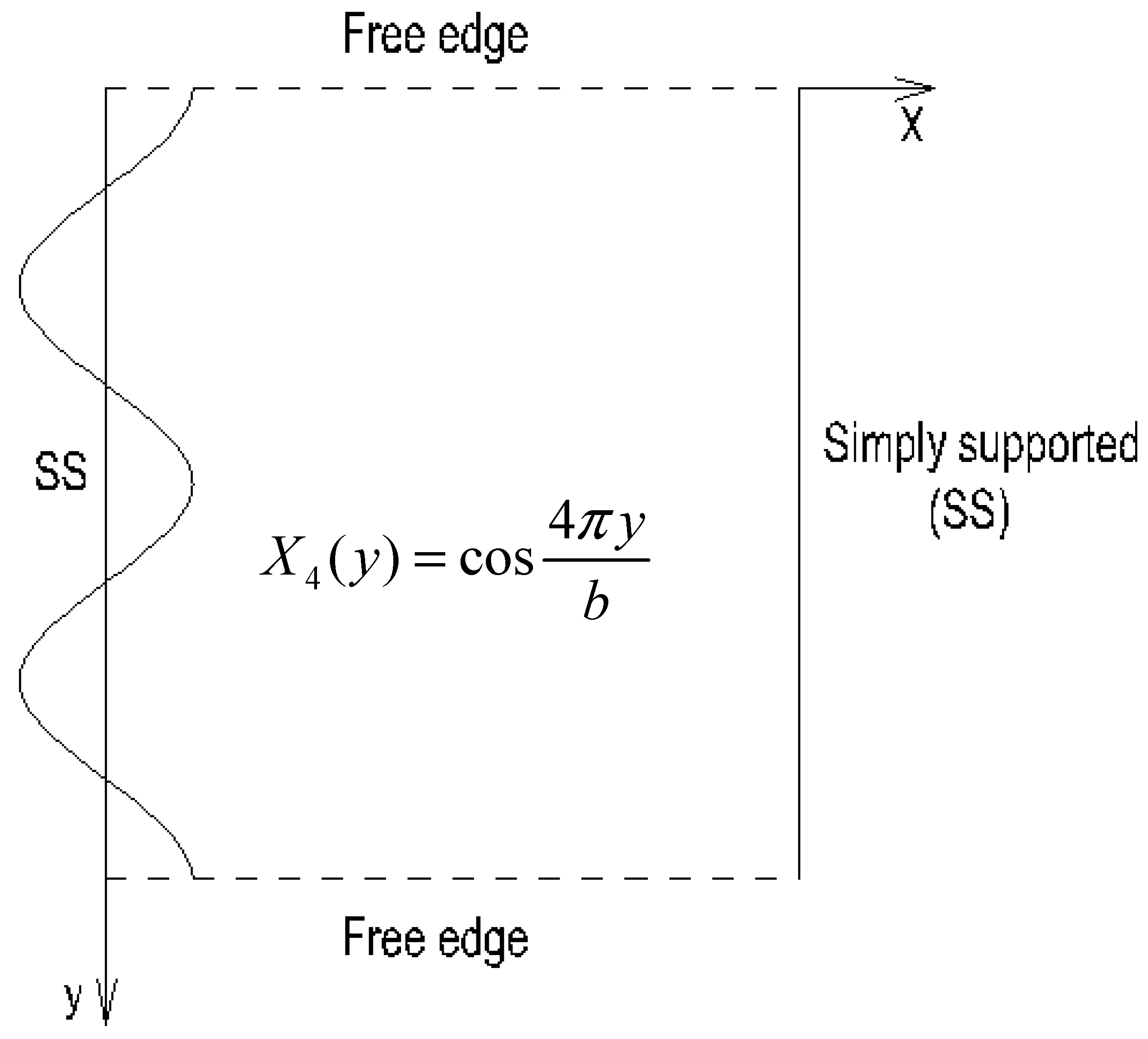
| b/a | 1.00 | 1.25 | |||||||
| Nx,cl | Nxm | Nym | Nx,cl | Nxm | Nym | ||||
| Czerny tables [14] (exact results) | |||||||||
| 18.3 | 59.5 | 44.1 | 12.7 | 34.2 | 45.8 | ||||
| Present study | |||||||||
| 1 redundant | 18.82 | 59.30 | 44.20 | 13.29 | 34.48 | 45.81 | |||
| 3 redundants | 18.29 | 59.31 | 44.03 | 13.03 | 34.34 | 45.74 | |||
| 5 redundants | 18.19 | 59.30 | 44.02 | 12.96 | 34.34 | 45.71 | |||
| b/a | 1.00 | 1.25 | |||||||
| Nx,cl | Ny,cl | Nxm | Nym | Nx,cl | Ny,cl | Nxm | Nym | ||
| Czerny tables [14] (exact results) | |||||||||
| 19.4 | 19.4 | 56.8 | 56.8 | 14.9 | 17.7 | 37.0 | 69.4 | ||
| Present study | |||||||||
| 2 redundant | 20.10 | 19.72 | 56.49 | 57.13 | 15.33 | 18.15 | 36.98 | 69.42 | |
| 6 redundants | 19.61 | 19.45 | 56.71 | 55.80 | 15.15 | 17.86 | 36.82 | 67.36 | |
| b/a | 1.00 | 1.20 | |||||||
| Nxm | Nym | Nx,frm | Nx,fre | Nxm | Nym | Nx,frm | Nx,fre | ||
| Czerny tables [14] (exact results) | |||||||||
| 21.42 | 79.85 | 16.60 | 7.89 | 27.91 | 143.64 | 23.29 | 11.40 | ||
| Present study | |||||||||
| 1 redundant | 20.92 | 70.85 | 16.21 | 7.69 | 26.56 | 116.24 | 22.44 | 10.85 | |
| 3 redundants | 21.42 | 79.89 | 16.61 | 7.97 | 27.89 | 144.74 | 23.28 | 11.41 | |
| 5 redundants | 21.40 | 79.77 | 16.59 | 7.90 | 27.87 | 143.53 | 23.27 | 11.40 | |
| b/a | 1.00 | 1.25 | 1.50 | ||||||
| Nx,fre | Nxfrm | Nx,fre | Nxfrm | Nx,fre | Nxfrm | ||||
| FEM results | |||||||||
| 16.58 | 42.42 | 15.32 | 36.52 | 14.61 | 33.35 | ||||
| Present study | |||||||||
| 2 redundant | 18.59 | 45.40 | 17.13 | 39.22 | 16.28 | 35.94 | |||
| 6 redundants | 16.40 | 44.15 | 15.44 | 37.89 | 14.88 | 34.52 | |||
| 10 redundants | 15.51 | 44.05 | 14.73 | 37.78 | 14.29 | 34.42 | |||
Disclaimer/Publisher’s Note: The statements, opinions and data contained in all publications are solely those of the individual author(s) and contributor(s) and not of MDPI and/or the editor(s). MDPI and/or the editor(s) disclaim responsibility for any injury to people or property resulting from any ideas, methods, instructions or products referred to in the content. |
© 2023 by the authors. Licensee MDPI, Basel, Switzerland. This article is an open access article distributed under the terms and conditions of the Creative Commons Attribution (CC BY) license (http://creativecommons.org/licenses/by/4.0/).


