
Submitted:
31 May 2023
Posted:
01 June 2023
Read the latest preprint version here
Abstract
This paper presents a design and performance analysis of a 10-element 5G massive MIMO antenna array for sub-6GHz mobile handsets, specifically for LTE bands 42/43/48/49 applications. The proposed antenna array consists of 10 closely spaced linearly polarized inverted-F antennas with a compact size of 20 × 9 mm2 of a single element. The proposed antenna array provides high gain, high efficiency, and low correlation between the antenna elements, which results in improved channel capacity, increased data rate, and enhanced signal quality. The performance of the antenna array is evaluated in terms of the radiation pattern, gain, efficiency, and correlation coefficient. The simulation and measured results show that the proposed antenna array achieves an approximate peak gain of 3.1 dBi at the resonance frequency, a total efficiency of 65 %, and a low correlation coefficient of 0.06 between the antenna elements. Therefore, the proposed 5G massive MIMO antenna array is a promising candidate for sub-6 GHz mobile handsets, particularly for LTE bands 42/43/48/49 applications
Keywords:
Antenna for handset
; m-MIMO
; sub-6 GHz
; LTE bands 42/43/48/49
; Future Generation
1. Introduction
The demand for faster data speeds, lower latency, and better coverage has increased as a result of the quick development of mobile communication services. Massive multiple-input multiple-output (MIMO) antenna arrays are projected to be used in fifth-generation (5G) wireless networks to meet these requirements because they can considerably boost the system’s capacity and spectral efficiency. Massive MIMO antenna arrays are difficult to integrate into mobile phones due to space constraints, low power requirements, and intricate antenna design.
Small, multi-standard compliant antenna systems that support a wide range of wireless protocols would be very useful for future portable gadgets. Multiple-input multiple-output (MIMO) aerial technology has become essential for the development of portable devices because of its ability to increase data throughput without increasing the power and bandwidth [1]. Due to their success without requiring more power or better spectrum efficiency, MIMO LONG-TERM EVOLUTION (LTE) systems have attracted a lot of attention. In a situation with severe fading, a multiple antenna system can often be used in MIMO mode or diversity mode [2]. There is currently a need for antennas with a wider bandwidth compact MIMO aerial with excellent isolation for 5G applications as a direct result of the development of new technologies and applications [3].
The next generation of high-bit-rate wireless communications will benefit from MIMO RF systems reduced multipath fading and increased channel capacity. Although important for the tiny size of today’s mobile designs, the physical structure must also effectively utilize the available space for these future ideas [4]. Due to the limited space allotted for smartphone antennas, it is technically difficult to construct a massive MIMO antenna system with less return loss or coupling [5].
In the latest research, many decoupling methods have been presented to enhance isolation for the MIMO system, including, parasitic element on the same layer with radiators [6], the neutralization line (NL) method for the first time in [7], etching slot technique [8,9], decoupling of ground branch technique [10,11,12] structures of metamaterial [13], and decoupling networks [14]. Several strategies have been proposed by researchers to limit mutual coupling between the radiators, including the use of a defective ground plane [15], structures with electromagnetic bandgap [16], and a perpendicular feeding network [17]. In order to achieve effective isolation, parasitic F-shaped stubs were utilized in [18] between the radiating patches. For the minimization of mutual coupling, a two-element MIMO aerial was equipped with an electric-LC resonator [19]. For improved isolation between the MIMO antennas, a stub followed by rectangular gaps in the ground plane was used in the design of the antenna [20]. In [21], a dual-band 8 × 8 antenna array is designed, in which a decoupling stub is used to reduce mutual coupling. To acquire enhanced isolation balanced antenna elements are used [22].
Flexible and bendable IoT devices are gaining popularity as new 5G and 6G network infrastructures are introduced [23,24]. The idea of wearable and flexible antennas is a critical problem to solve in this regard [25,26]. Scientific work focused on developing small, wearable flexible antennas to meet contemporary demands [27]. The fifth generation (5G) of mobile communication, is on the horizon in the contemporary communication environment where technologies are evolving at a very fast rate [28]. The main advantages of 5G are higher data rates than fourth-generation (4G) mobile communication, short time latency, increased channel capacity, and superior spectral efficiency [29]. Modes for high-capacity communications are provided by Fifth generation mobile networks (5G) after assigning new frequency bands in the Radiofrequency spectrum to [30].
In the latest research regarding wireless communications, some researchers have described the MIMO antennas for recent 5G smartphones [31,32,33], however, some of the research on dual-band antenna systems has been published [34]. MIMO technology is used by LTE to increase the effectiveness of radio spectrum usage. MIMO aerial is anticipated to be a crucial component of LTE networks [35]. MIMO systems were originally used in a common mobile phone network called HSDPA (High-Speed Downlink Packet Access). Shortly later, MIMO technology was first employed as the foundation for the LTE standard [36]. The 3400-3800 MHz band, which unites LTE bands 42 (3400-3600 MHz) and 43 (3600-3800 MHz), has received recognition from many countries as a pioneer in the development of 5G massive MIMO. A decision by the European Union (EU) to prioritize the development of the 3400-3800 MHz spectrum is one example. [37], China is looking into using the sub-6GHz and 3400-3600 MHz bands for 5G. [38], and Korea’s decision to conduct their exploratory research in the 3400–3700 MHz band [39]. The next 5G multiband communication will require more than LTE bands 42 and 43, though. LTE band 46 (5150–5925 MHz), commonly known as an unlicensed band (LTE–U), is only used for licensed–assisted access (LTE–LAA) operations. [40], is also important to consider when designing the 5G massive MIMO aerial to enable additional sub-6GHz frequency channels.
Taking into consideration the previous analysis of the problems of MIMO antenna structures in 5G, a MIMO antenna array is presented for the upcoming 5G mobile handset applications. The proposed antenna array functions in the sub-6 GHz’s 5G bands. The design of the article is arranged as follows. Section 2 clears the structure of the designed MIMO antenna array. In Section 3, the results are discussed and compared in simulation software, and in measurement setup of the proposed MIMO antenna array such as antenna efficiency, radiation pattern, ECC, and S-parameter are described in detail. Section 4 brings the article to a conclusion.
2. Methodology
The front view of a single element in a ten-port massive MIMO antenna is shown in Figure 1, along with its complete detailed dimensions. The compact size of each array element is 9 × 3.5 at 3.6 GHz, printed symmetrically on the long side of "Rogers RT/duroid 5880 (tm)". The thickness of a substrate is 0.79 , its dielectric constant () is 2.2, and the loss tangent is 0.02. The main PCB has dimensions of 150 × 70 × 0.79 . The 50 microstrip-line feeds are printed on the main PCB to excite the inverted-F radiator. A 150 × 70 ground plane is etched on the back side of the PCB. Planer inverted F-shaped structures are grouped for each radiating element. On the back side of the substrate, two slots were etched, the ground cut with length = 10 to achieve a better band, and the isolation cut with a length of 8 are imprinted to achieve better isolation. Additionally, in Figure 1 and Figure 2 all the detailed dimensions of the 10 × 10 massive MIMO antenna are clearly mentioned inside the view.
The dimensions pw1, pw2, pw3, pl1, pl2, pl3, pl4, and pl5 represent the widths and lengths of patch stubs in an inverted-F antenna. And, fl, fw are the length and width of the 50 impedance feedline. The dimensions gcw1, gcw2, gcl1, and gcl2 show the width and length of ground slots, whereas gap1 and gap2 are the separations between ground slots. A gap3 is the distance of the topmost slot from the upper corner and gap4 is the distance of the bottom slot from the lower corner. For better understanding, maintaining the minimum distances between each antenna will offer the most elements that’s why such acceptable isolation is obtained of the 10 × 10 MIMO antenna. All the parameters and dimensions of a planar inverted F-shaped antenna are mentioned herein from Figure 1 and Figure 2 in Table 1.
Figure 1 showed the magnified view of the Ant1. The vertical arm of an inverted F-shaped strip has length = 9 and width =3.5 . The horizontal arms of inverted F-shaped length = 1, = 1 and width = 7 , = 5 . The F-shaped monopole element is kept farther apart so that the gap (g) between two F-shaped elements i.e., from the bottom of the inverted F-shaped to the top of it, is maintained as g = 22 . = 16.5 and = 2.43 are the length and width of the microstrip-line feed respectively which is printed on the main system PCB. The lowest horizontal arm of the inverted F-shaped monopole antenna has a gap =1.785 with the feedline. The fabricated prototype is presented in Figure 3.
3. Results and Discussions
Figure 3 shows the front and back prototypes, as well as the proposed 10-element 5G MIMO antenna, which have been constructed and tested. All 10-element antenna feeding points are directly coupled through the ground plane to the 50-ohm SMA connection. The next subsections detail the measured and simulated results as well as all of the performance matrices of this proposed 5G MIMO antenna.
3.1. S-PARAMETERS
Figure 4 shows the measurement of s-parameters of the proposed Ant1. The graph shows that the proposed Ant1’s reflection coefficient is greater than -6 dB (VSWR 3:1). The simulated results of Ant1 have shown desirable impedance bandwidths of 5.71% (3500- 4200 MHz) which covers the LTE bands, such as LTE 42/43 and LTE 48/49 respectively.
The simulated results of the designed MIMO antenna array from antenna 1 to antenna 5 as in the sequence of Figure 3 are depicted in Figure 5. From Figure 5, the simulated reflection coefficients are shifted to a higher frequency of around 100 MHz. According to analysis, the reflection coefficient is significantly better than -6 dB for all operational bands (3:1 VSWR, voltage standing wave ratio) and covers LTE bands LTE 42/43 and LTE 48/49, respectively. Throughout the entire investigation, there was a significant correlation found in the simulation setup. The suggested antenna has demonstrated desirable measured -6 dB impedance bandwidths of 5.71 % (3500–4200 MHz). It can be demonstrated that the magnitude of isolation has a value of less than -9.45 dB throughout all four working bands of various antenna pairs. Figure 6 illustrates the simulated coupling isolation between the antennas of our designed MIMO antenna array, which is much lower than -9 dB, which is an excellent measurement. This demonstrates that our suggested design’s coupling isolation between the antennas also covers the frequency range of (3500–4200 MHz), which corresponds to the LTE 42/43 and LTE 48/49 bands, respectively.
3.1.1. Diversity Gain and Envelop Correlation Coefficient
Investigating the diversity and multiplexing performances is crucial since, in addition to reflection, isolation, and radiation performances, diversity and multiplexing applications are the principal uses for the MIMO antenna. This section investigates the envelope correlation coefficients (ECCs) of various antenna pairs to assess and validate the diversity performance of the proposed MIMO antenna array [51]. The precise algorithm used to calculate the ECC has been made clear in [52]. Figure 7 demonstrates the proposed MIMO antenna’s simulated diversity gain.
Figure 8 shows the simulated ECC of the proposed antenna. The proposed MIMO antenna ECCs were determined using the data from the measured complex electric field. It can be seen in Figure 8 that the calculated ECC values in LTE bands 42/43 and 48/49 were less than 0.25, which is significantly better than the required ECC value of less than 0.5. The proposed MIMO antenna array has desirable diversity capabilities since lower ECC values will result in higher diversity gain.
3.2. Gain of an antenna
Figure 9 shows the measured gain of a single element of the proposed 5G MIMO antenna. The lowest and maximum gain of the proposed 5G MIMO antenna covers the necessary LTE 42/43 and LTE 48/49 bands, respectively, with a minimum gain of 2.5 dBi and a maximum gain of 5.09 dBi. The maximum and minimum gain have values that are suitable for the suggested design and cover the necessary bands.
4. Conclusion
The main target of this article is to design a 5G massive MIMO antenna array that can provide a high gain, high efficiency, and a minimum coefficient of correlation joining the antenna section. The suggested antenna array is anticipated to raise data rates, increase channel capacity, and improve signal quality in order to fulfill the needs of 5G wireless networks. The radiation pattern, gain, efficiency, and correlation coefficient are used to assess how well the planned antenna array performs. According to the simulation results, the suggested antenna array has a low correlation coefficient between the antenna elements, a peak gain of 9.5 dBi, and a total efficiency of 67 %. In conclusion, the suggested 10-element 5G massive MIMO antenna array is a potential option for mobile devices operating below 6 GHz, especially for LTE bands 42/43/48/49 applications. The system capacity and spectral efficiency of 5G wireless networks can both be greatly increased by the suggested antenna array. The proposed prototype is compared with some MIMO antennas for smartphones literature in Table 2.
References
- Abubaker Ahmed Elobied, Xue-Xia Yang, Ningjie Xie, Steven Gao, "Dual-Band 2 × 2 MIMO Antenna with Compact Size and High Isolation Based on Half-Mode SIW", International Journal of Antennas and Propagation, vol. 2020, Article ID 2965767, 11 pages, 2020. [CrossRef]
- S. Zhang, K. Zhao, Z. Ying and S. He, "Adaptive Quad-Element Multi-Wideband Antenna Array for User-Effective LTE MIMO Mobile Terminals," in IEEE Transactions on Antennas and Propagation, vol. 61, no. 8, pp. 4275-4283, Aug. 2013. [CrossRef]
- Liu, X., Zhang, J., Xi, H., Yang, X., Sun, L. and Gan, L., 2022. A Compact Four-band High-isolation Quad-port MIMO Antenna for 5G and WLAN Applications. AEU-International Journal of Electronics and Communications, p.154294. [CrossRef]
- Elfergani, I., Hussaini, A. S., Abd-Alhameed, R., See, C., Child, M., & Rodriguez, J. (2012). Design of a compact tuned antenna system for mobile MIMO applications.
- J. Dong, S. Wang, and J. Mo, "Design of a Twelve-Port MIMO Antenna System for Multi- Mode 4G/5G Smartphone Applications Based on Characteristic Mode Analysis," in IEEE Access, vol. 8, pp. 90751-90759, 2020. [CrossRef]
- Z. Li, Z. Du, M. Takahashi, K. Saito, and K. Ito, “Reducing mutual coupling of MIMO antennas with parasitic elements for mobile terminals,” IEEE Trans. Antennas Propag., vol. 60, no. 2, pp. 473–481, Feb. 2012. [CrossRef]
- Li, M., Jiang, L. & Yeung, K. L. A general and systematic method to design neutralization lines for isolation enhancement in MIMO antenna arrays. IEEE Trans. Vehicular Technol. (2020). [CrossRef]
- M. Ikram, M. S. Sharawi, A. Shamim, and A. Sebak, “A multiband dualstandard MIMO antenna system based on monopoles (4G) and connected slots (5G) for future smart phones,” Microw. Opt. Technol. Lett., vol. 60, no. 6, pp. 1468–1476, Jun. 2018. [CrossRef]
- Q. Sun, B. Sun, L. Sun, W. Huang, and Q. Ren, “Broadband two-element array with hybrid decoupling structures for multimode mobile terminals,” IEEE AntennasWireless Propag. Lett., vol. 14, pp. 1431–1434, 2015. [CrossRef]
- S. Wang and Z. Du, “A dual-antenna system for LTE/WWAN/WLAN/WiMAX smartphone applications,” IEEE Antennas Wireless Propag. Lett., vol. 14, pp. 1443–1446, 2015. [CrossRef]
- J. Dong, X. Yu, and L. Deng, “A decoupled multiband dual-antenna system forWWAN/LTE smartphone applications,” IEEE Antennas Wireless Propag. Lett., vol. 16, pp. 1528–1532, 2017.
- Z. An and M. He, “A Multiband Dual-Antenna System for MIMO Operation in Mobile Terminals,” Appl. Comput. Electromagn. Soc. J., vol. 34, no. 10, pp. 1529–1534, Oct. 2019.
- K. Yu, Y. Li, and X. Liu, “Mutual coupling reduction of a MIMO antenna array using 3D novel meta material structures,” Appl. Comput. Electromagn. Soc. J., vol. 33, no. 7, pp. 758–763, 2018.
- M.-Y. Li, Y.-L. Ban, Z.-Q. Xu, J. Guo, and Z.-F. Yu, “Tri-polarized 12-antenna MIMO array for future 5G smartphone applications,” IEEE Access, vol. 6, pp. 6160–6170, 2018. [CrossRef]
- Zhu, F.-G., Xu, J.-D. & Xu, Q. Reduction of mutual coupling between closely-packed antenna elements using defected ground structure. Electron. Lett. 45, 601–602 (2012). [CrossRef]
- Suntives, A. & Abhari, R. Miniaturization and isolation improvement of a multiple-patch antenna system using electromagnetic bandgap structures. Microw. Opt. Technol. Lett. 55, 1609–1612 (2013). [CrossRef]
- Adamiuk, G., Beer, S., Wiesbeck, W. & Zwick, T. Dual-orthogonal polarized antenna for UWB-IR technology. IEEE Antennas Wireless Propag. Lett. 8, 981–984 (2009). [CrossRef]
- Iqbal, A., Saraereh, O. A., Ahmad, A. W. & Bashir, S. Mutual coupling reduction using F-shaped stubs in UWB-MIMO antenna. IEEE Access. 6, 2755–22759 (2017). [CrossRef]
- Pandit, S., Mohan, A., Ray, P. A compact planar MIMO monopole antenna with reduced mutual coupling for WLAN applications using ELC resonator. in Proc. IEEE Microw. Conf. (APMC), pp. 1–4 (2016).
- Verma, A.K., Nakkeeran, R., Vardhan, R.K. Design of 2x2 single-sided wrench-shaped UWB MIMO antenna with high isolation. in Proc. IEEE Int. Conf. Circuit, Power Comput. Technol. (ICCPCT), pp. 1–3 (2016).
- Cui, L., J. Guo, Y. Liu, and C. Sim, “An 8-element dual-band MIMO antenna with decoupling stub for 5G smartphone applications,” IEEE Antennas and Wireless Propagation Letters, Vol. 18, No. 10, 2095–2099, Oct. 2019. [CrossRef]
- Li, Y., C. Sim, Y. Luo, and G. Yang, “High isolation 3.5 GHz eight antenna MIMO array using balanced open-slot antenna element for 5G smartphones,” IEEE Transactions on Antenna and Propagation, Vol. 67, No. 6, 3820–3830, 2019. [CrossRef]
- Li, S., Da Xu, L. & Zhao, S. 5G Internet of Tings: A survey. J. Ind. Inf. Integr. 10, 1–9 (2018).
- Corzo, D., Tostado-Blazquez, G. & Baran, D. Flexible electronics: Status, challenges and opportunities. Front. Electron. 1, 1–13 (2020). [CrossRef]
- Marasco, I. et al. Compact and fexible meander antenna for surface acoustic wave sensors. Microelectron. Eng. 227, 111322 (2020).
- Niro, G. et al. Design of a surface acoustic wave resonator for sensing platforms. IEEE International Symposium on Medical Measurements and Applications (MeMeA) 1–6 (2020).
- Marasco, I., Niro, G., Mastronardi, V.M. et al. A compact evolved antenna for 5G communications. Sci Rep 12, 10327 (2022). [CrossRef]
- Jiang, W., Y. Cui, B. Liu, W. Hu, and Y. Xi, “A dual-band MIMO antenna with enhanced isolation for 5G smartphone applications,” IEEE Access, Vol. 7, 112554–112563, 2019. [CrossRef]
- Thakur, Vishakha & Jaglan, Naveen & Dev Gupta, Samir. (2020). Design of a Dual-Band 12- Element MIMO Antenna Array for 5G Mobile Applications. Progress In Electromagnetics Research Letters. 95. 73-81. [CrossRef]
- J. Kurvinen, H. Khknen, A. Lehtovuori, J. Ala- Laurinaho and V. Vi- ikari, “Co-designed mm- wave and LTE handset antennas,” IEEE Trans. Antennas Propag., vol. 67, no. 3, pp. 1545-1553, March 2019. [CrossRef]
- Y. L. Ban, C. Li, C. Y. D. Sim, G. Wu, and K.-L. Wong, “4G/5G multiple antennas for future multi-mode smartphone applications,” IEEE Access, vol. 4, pp. 2981-2988, July 2016. [CrossRef]
- M. Y. Li, Y. L. Ban, Z. Q Xu, G.Wu, C. Sim, K. Kang, and Z. F. Yu, “Eight-port orthogonally dual-polarized antenna array for 5G smartphone applications,” IEEE Trans. Antennas Propag., vol. 64, no. 6, pp. 3820-3830, June 2016. [CrossRef]
- Zhao and Z. Ren “Multiple-input and multiple- output antenna system with self-isolated antenna element for fifth generation mobile terminals” Microw. Opt. Technol. Lett., vol 61, no. 1, pp. 20-27, Jan. 2019.
- Z. Ren, A. Zhao and S. Wu, “Dual-Band MIMO Antenna System for 5G Mobile Terminals,” 2019 13th European Conference on Antennas and Propagation (EuCAP), Krakow, Poland, pp. 1-4, 2019.
- Andrews Christina Malathi and Dhanasingh Thiripurasundari, "Compact 2×1 MIMO Antenna System for LTE Band," Progress In Electromagnetics Research C, Vol. 75, 63-73, 2017.
- F. Alexa, B. Bardeanu and D. Vatau, "MIMO antenna system for LTE," 2013 36th International Conference on Telecommunications and Signal Processing (TSP), Rome, Italy, 2013, pp. 294-298. [CrossRef]
- Qualcomm. (Sep. 2015). Making the Best Use of Licensed and Unlicensed Spectrum. [Online]. Available: https://www.qualcomm.com/media/documents/files/making-the-best-use-of-unlicensed-spectrumpresentation.pdf.
- IMT-2020 (5G) Promotion Group. (Feb. 2015). White Paper on 5G Concept. [Online]. Available: http://www.imt-2020.org.cn/zh/ documents/download/4.
- SK Telecom. (Oct. 2014).SK Telecom 5G White Paper.[Online]. Available:http://www.sktelecom.com/img/pds/press/SKT-5G%20White%20Paper_V1.0_Eng.pdf.
- H. Xu et al., “A compact and low-profile loop antenna with six resonant modes for LTE smartphone,” IEEE Trans. Antennas Propag., vol. 64, no. 9, pp. 3743–3751, Sep. 2016. [CrossRef]
- H. Zou, Y. Li, C.-Y.-D. Sim, and G. Yang, “Design of 8 × 8 dual-band MIMO antenna array for 5G smartphone applications,” Int. J. RF Microw. Comput.-Aided Eng., vol. 28, no. 9, p. e21420, 2018.
- J. L. Guo, L. Cui, C. Li, and B. H. Sun, “Side-edge frame printed eight-port dual-band antenna array for 5G smartphone applications,” IEEE Trans. Antennas Propag., vol. 66, no. 12, pp. 7412–7417, Dec. 2018. [CrossRef]
- Y. Li, C.-Y.-D. Sim, Y. Luo, and G. Yang, “Metal-frame-integrated eight-element multiple-input multiple-output antenna array in the long term evolution bands 41/42/43 for fifth generation smartphones,” Int. J. RF Microw. Comput.-Aided Eng., vol. 29, no. 1, Jan. 2019, Art. no. e21495.
- H. Wang, R. Zhang, Y. Luo, and G. Yang, “Compact eight-element antenna array for triple-band MIMO operation in 5G mobile terminals,” IEEE Access, vol. 8, pp. 19433–19449, 2020. [CrossRef]
- Y. Li, C.-Y.-D. Sim, Y. Luo, and G. Yang, “12-port 5G massive MIMO antenna array in sub-6 GHz mobile handset for LTE bands 42/43/46 applications,” IEEE Access, vol. 6, pp. 344–354, Oct. 2017.
- N. Jaglan, S. D. Gupta, and M. S. Sharawi, “18 element massive MIMO/diversity 5G smartphones antenna design for sub-6 GHz LTE bands 42/43 applications,” IEEE Open J. Antennas Propag., vol. 2, pp. 533–545, 2021.
- J. Huang, G. Dong, J. Cai, H. Li, and G. Liu, “A quad-port dualband MIMO antenna array for 5G smartphone applications,” Electronics, vol. 10, no. 5, p. 542, Feb. 2021. [CrossRef]
- J. Huang, G. Dong, Q. Cai, Z. Chen, L. Li, and G. Liu, “Dual-band MIMO antenna for 5G/WLAN mobile terminals,” Micromachines, vol. 12, no. 5, p. 489, Apr. 2021. [CrossRef]
- D. Serghiou, M. Khalily, V. Singh, A. Araghi, and R. Tafazolli, “Sub-6 GHz dual-band 8 × 8 MIMO antenna for 5G smartphones,” IEEE Antennas Wireless Propag. Lett., vol. 19, no. 9, pp. 1546–1550, Sep. 2020. [CrossRef]
- L. Cui, J. Guo, Y. Liu, and C.-Y.-D. Sim, “An 8-element dual-band MIMO antenna with decoupling stub for 5G smartphone applications,” IEEE Antennas Wireless Propag. Lett., vol. 18, no. 10, pp. 2095–2099, Oct. 2019. [CrossRef]
- M. S. Sharawi, "Printed Multi-Band MIMO Antenna Systems and Their Performance Metrics [Wireless Corner]," in IEEE Antennas and Propagation Magazine, vol. 55, no. 5, pp. 218-232, Oct. 2013. [CrossRef]
- Y. Li, C. -Y. -D. Sim, Y. Luo and G. Yang, "12-Port 5G Massive MIMO Antenna Array in Sub-6GHz Mobile Handset for LTE Bands 42/43/46 Applications," in IEEE Access, vol. 6, pp. 344-354, 2018. [CrossRef]
Figure 1.
(a) Dimensions and geometry of front view of the proposed MIMO antenna design (b) dimensions of top layer
Figure 1.
(a) Dimensions and geometry of front view of the proposed MIMO antenna design (b) dimensions of top layer
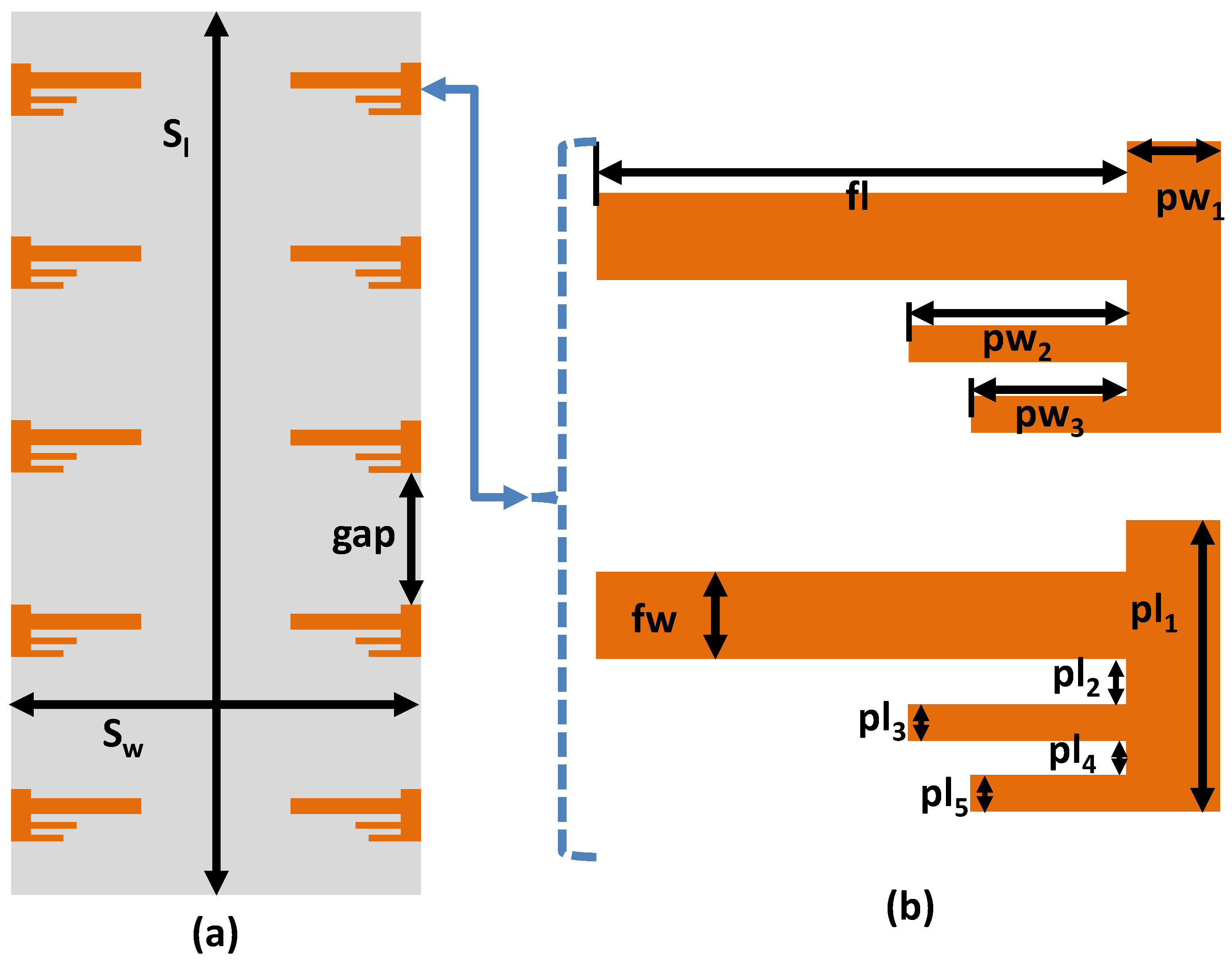
Figure 2.
(a) Dimensions and geometry of back view of the proposed MIMO antenna configuration (b) dimensions of bottom layer
Figure 2.
(a) Dimensions and geometry of back view of the proposed MIMO antenna configuration (b) dimensions of bottom layer
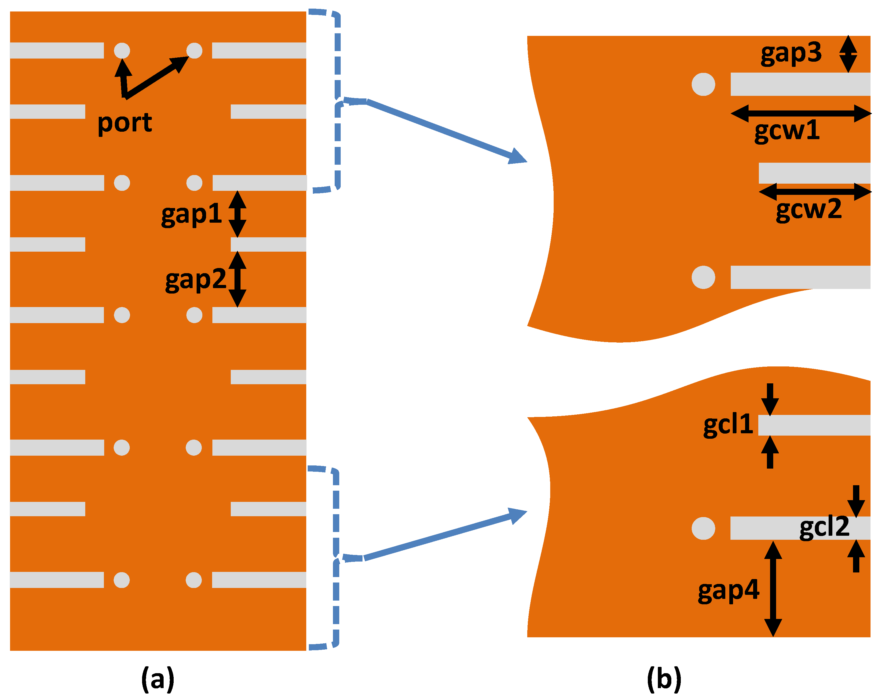
Figure 3.
Fabricated prototype (a) Front view (b) Back view
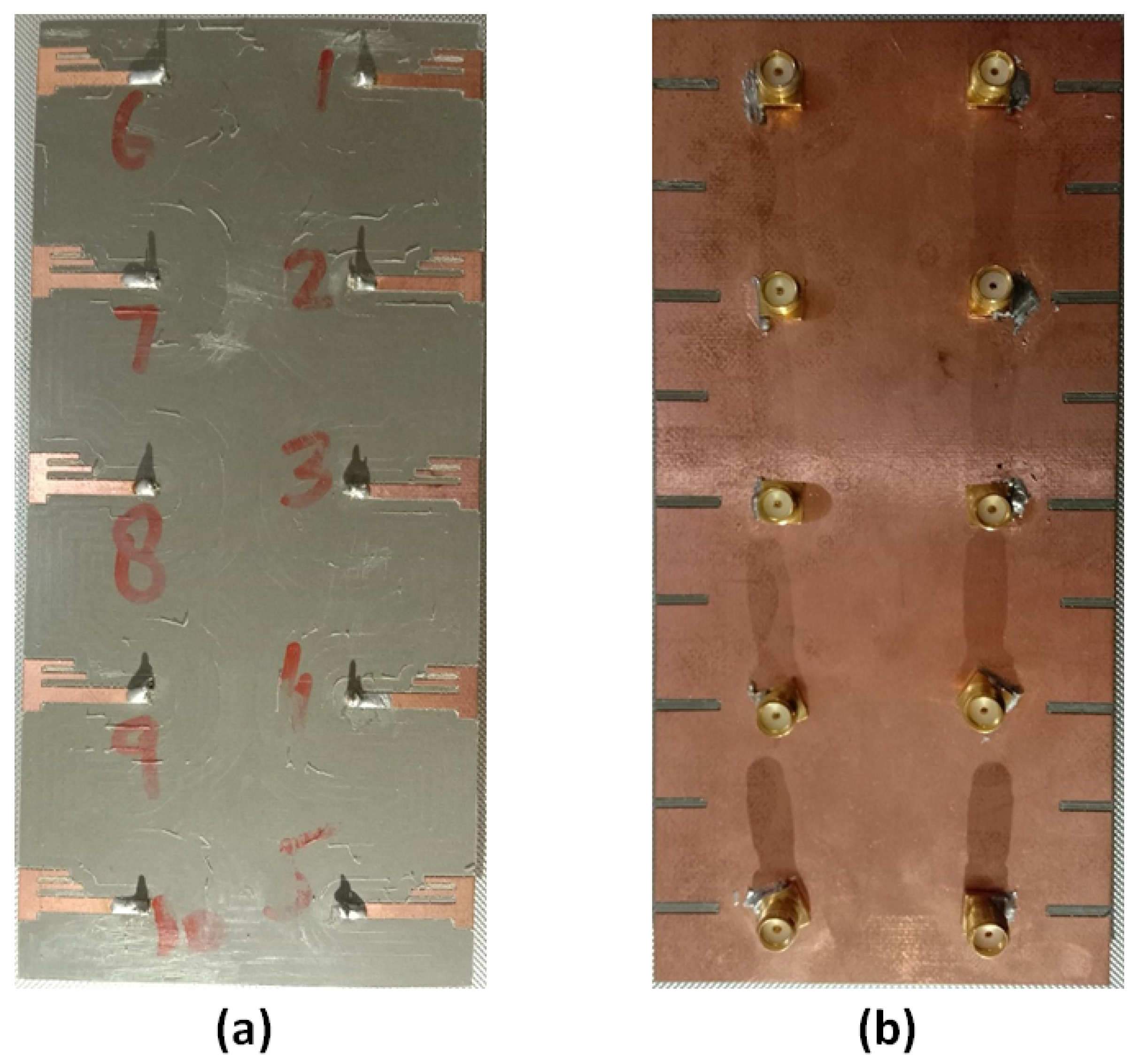
Figure 4.
Measured reflection coefficient S of antenna 1.
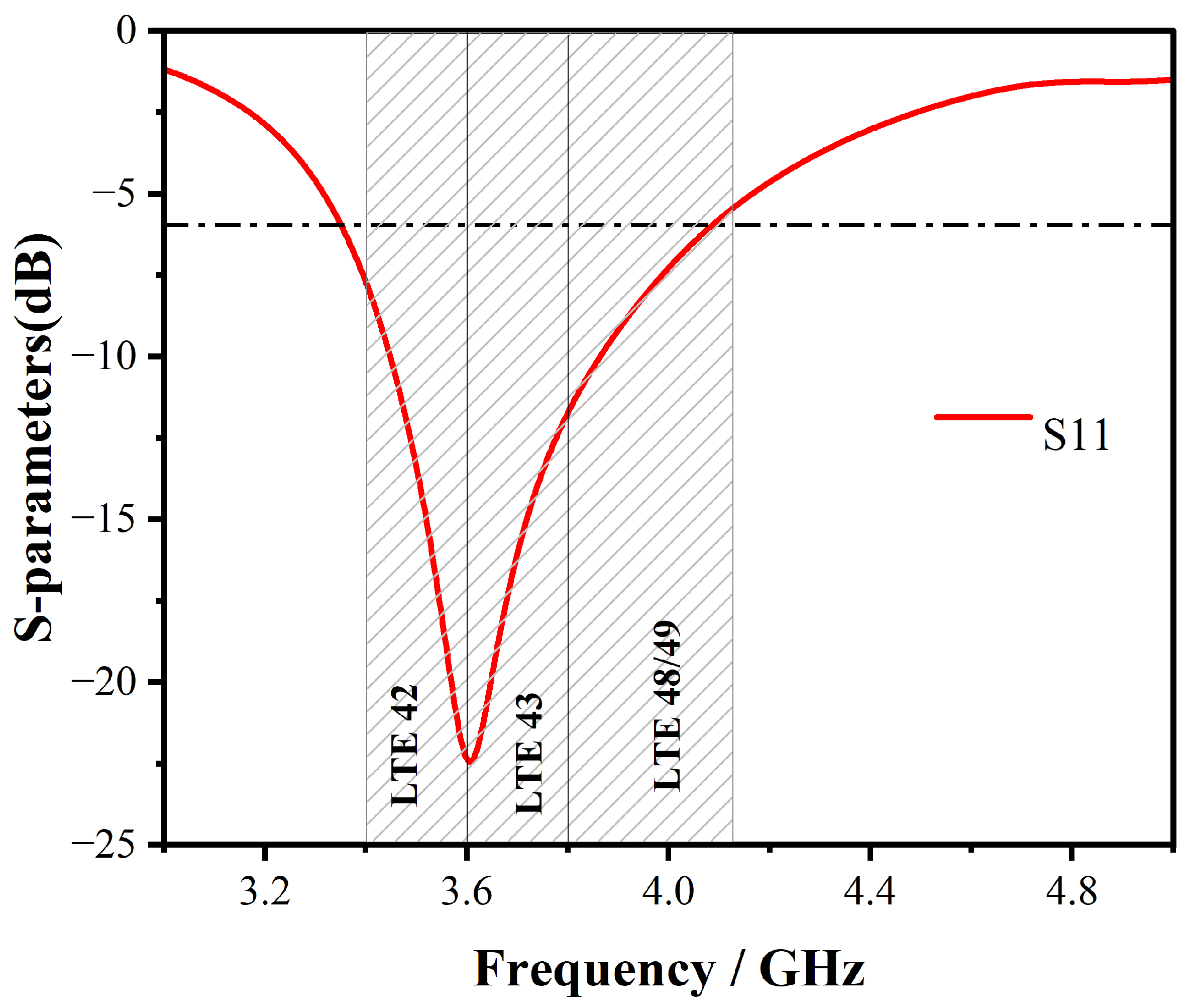
Figure 5.
Simulated reflection coefficients of Ant 1 to Ant 5.
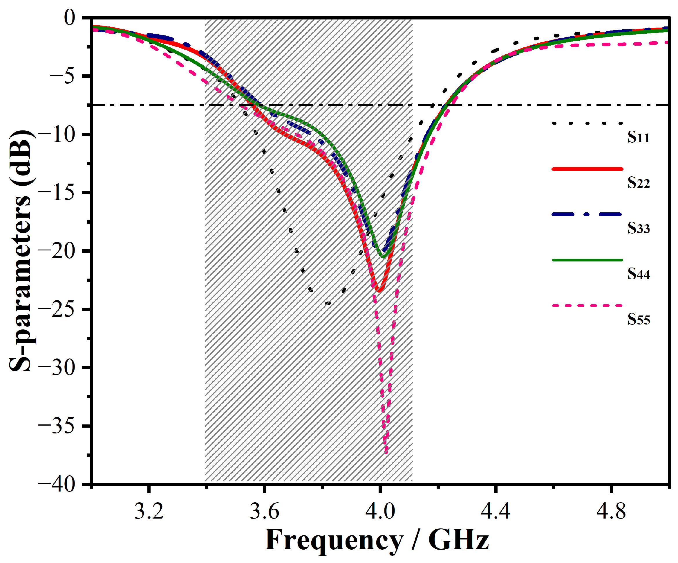
Figure 6.
Simulated transmission coefficients (coupling) between different antenna pairs.
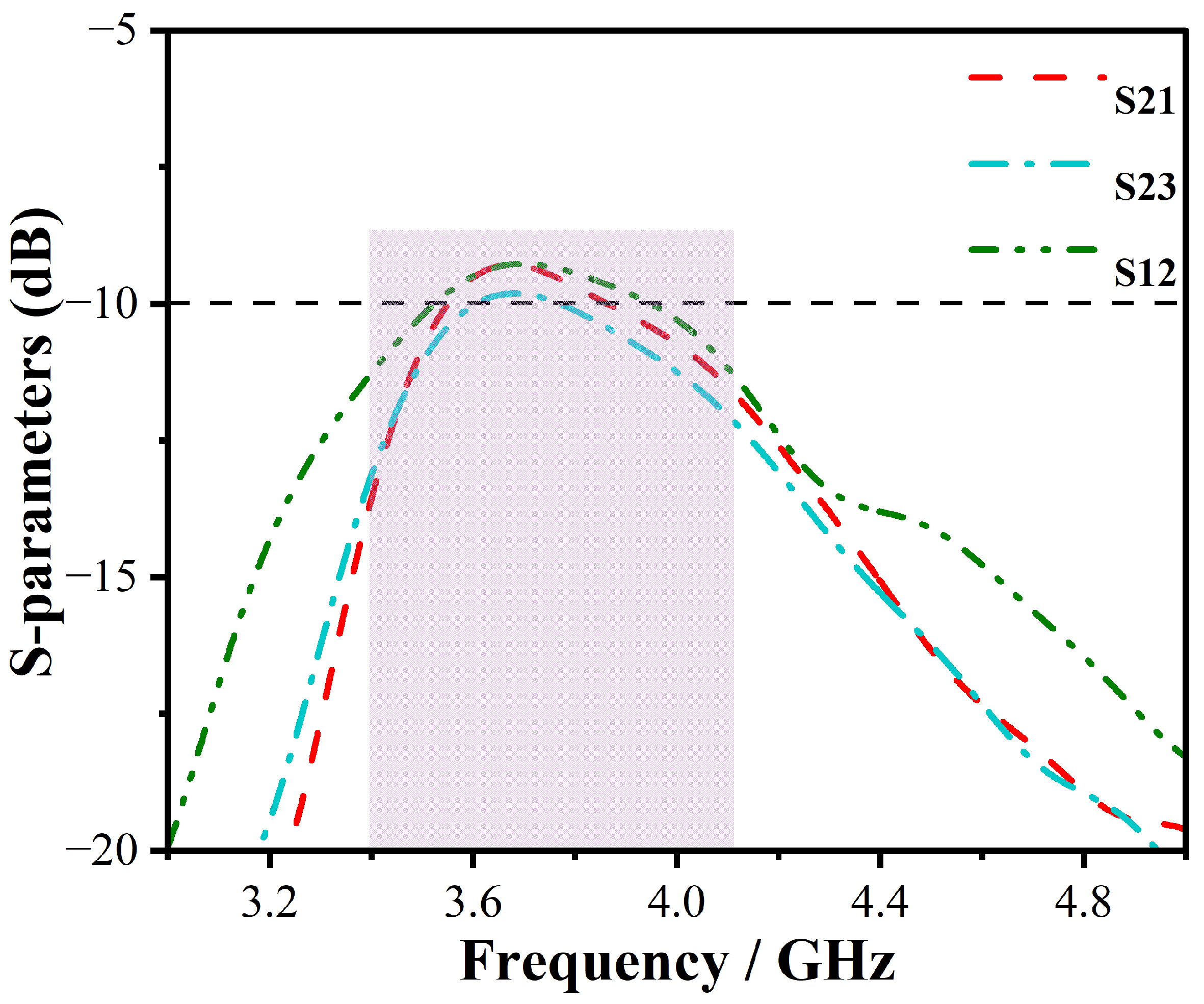
Figure 7.
Simulated Diversity Gain of proposed antenna
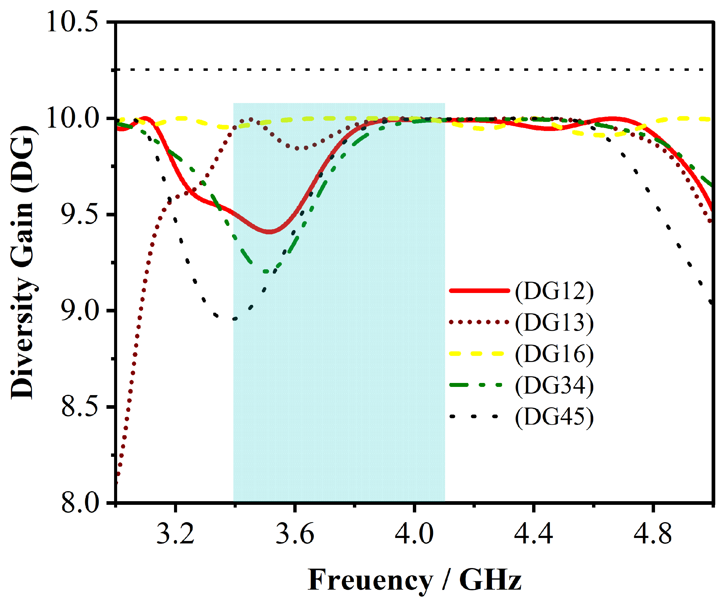
Figure 8.
calculated values for the envelope correlation coefficient (ECC) based on measurements made in the LTE bands 42/43 and 48/49.
Figure 8.
calculated values for the envelope correlation coefficient (ECC) based on measurements made in the LTE bands 42/43 and 48/49.
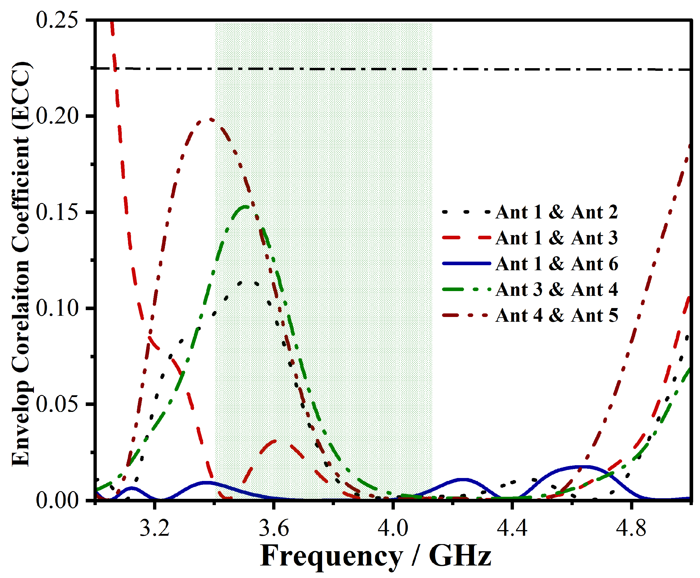
Figure 9.
Measured Gain of a Single Element
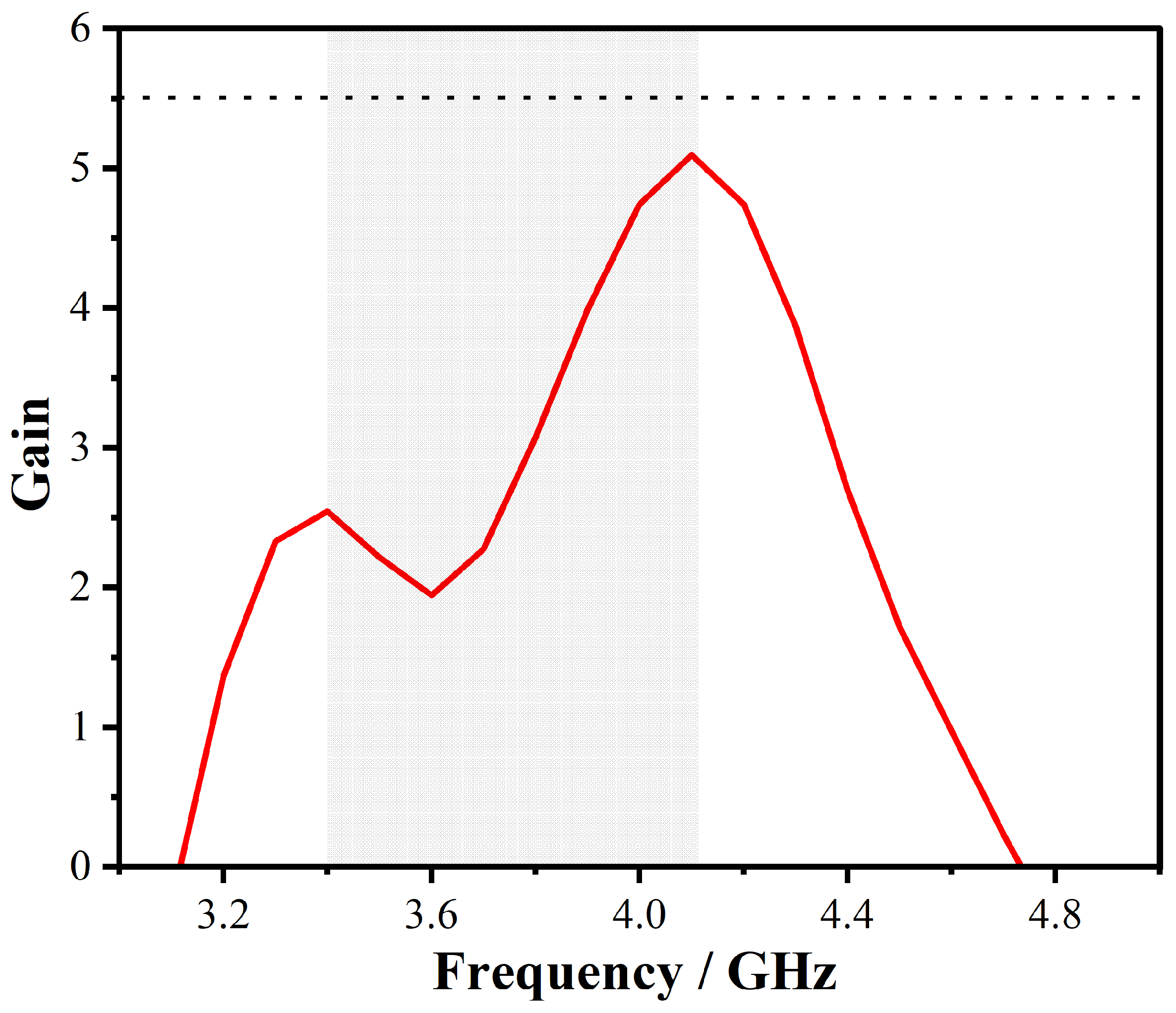

Table 1.
Parameters of a Proposed Antenna
| Parameter | Value () | Parameter | Value () | Parameter | Value () |
|---|---|---|---|---|---|
| S | 150 | S | 70 | gap | 22 |
| fl | 16.5 | fw | 2.43 | pw | 3.5 |
| pw | 7 | pw | 5 | pl | 9 |
| pl | 1.785 | pl | 1 | pl | 1 |
| pl | 1 | gap1 | 12.8 | gap2 | 15 |
| gap3 | 9.15 | gap4 | 15.15 | gcw1 | 9.99 |
| gcw2 | 8 | gcl1 | 1.5 | gcl | 1.7 |
Table 2.
Performance comparison of various state-of-the-art 5G antennas.
| Reference | Bandwidth (GHz) | Isolation (-dB) | ECC | Total Efficiency (%) | Radiator size in () | Impedance Bandwidth (%) | Peak Channel Capacity () |
|---|---|---|---|---|---|---|---|
| [Proposed] | 3.4-3.6,3.550-3.7 (-6dB) | >10 | <0.19 | >67 | 0.17 × 0.05 × 0.01 | 5.71 | 45 (10 × 10) |
| [41] | 3.4-3.6,5.15-5.925 (-6dB) | >12 | <0.1 | >50 | 0.17 × 0.05 × 0.01 | 19.71 | 38.8 (8 × 8) |
| [42] | 3.4-3.6,4.8-5.1 (-6dB) | >12 | <0.1 | 40-85 | 0.17 × 0.03 × 0.01 | 11.77 | 38.5 (8 × 8) |
| [43] | 2.496-2.69, 3.4-3.8 (-6dB) | >10.5 | <0.2 | 44-66 | 0.02 × 0.17 × 0.01 | 18.59 | 38.3 (8 × 8) |
| [44] | 3.35-3.82, 4.79-6.2 (-6dB) | >10.5 | <0.12 | >43 | 0.17 × 0.03 × 0.01 | 41.77 | 37.6 (8 × 8) |
| [45] | 3.4-3.8, 5.15-5.925 (-6dB) | >12 | <0.15 | 41-79 | 0.13 × 0.04 × 0.01 | 25.11 | 29.5 (6 × 6) |
| [46] | 3.4-3.6, 3.6-3.8 (-10dB) | >20 | <0.01 | >87 | 0.11 × 0.04 × 0.02 | 11.11 | 81 (18 × 18) |
| [47] | 3.4-3.6, 4.8-5 (-10dB) | >16.5 | <0.01 | 82-85 | 0.16 × 0.07 × 0.01 | 9.79 | Not Mentioned (4 × 4) |
| [48] | 3.3-3.8, 4.8-5, 5.15-5.35, 5.725-5.85 (-10dB) | >15 | <0.02 | >70 | 0.16 × 0.07 × 0.01 | 24.02 | Not Mentioned (4 × 4) |
| [49] | 3.1-3.85, 4.8-6 (-10dB) | >17 | <0.06 | 65-71 | 0.20 × 0.05 × 0.01 | 36.17 | 39 (8 × 8) |
| [50] | 3.3-4.2, 4.8-5.0 (-6dB) | >10 | <0.12 | 53.8-79.1 | 0.21 × 0.07 × 0.01 | 28.10 | 39.5 (8 × 8) |
Disclaimer/Publisher’s Note: The statements, opinions and data contained in all publications are solely those of the individual author(s) and contributor(s) and not of MDPI and/or the editor(s). MDPI and/or the editor(s) disclaim responsibility for any injury to people or property resulting from any ideas, methods, instructions or products referred to in the content. |
© 2023 by the authors. Licensee MDPI, Basel, Switzerland. This article is an open access article distributed under the terms and conditions of the Creative Commons Attribution (CC BY) license (http://creativecommons.org/licenses/by/4.0/).
Copyright: This open access article is published under a Creative Commons CC BY 4.0 license, which permit the free download, distribution, and reuse, provided that the author and preprint are cited in any reuse.


