Submitted:
28 August 2023
Posted:
29 August 2023
You are already at the latest version
Abstract
Keywords:
1. Introduction
2. Methodology
3. Results and Discussions
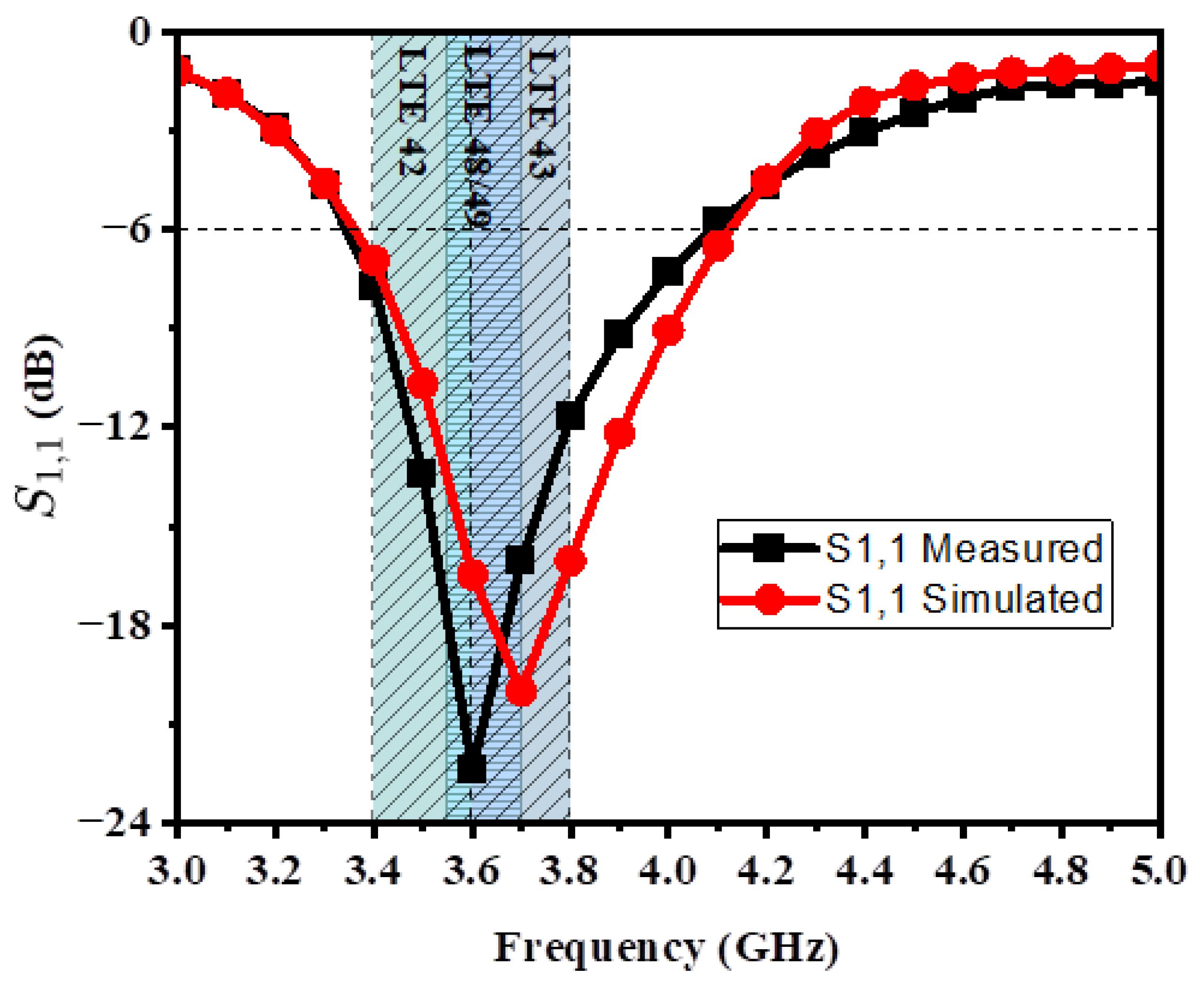
3.1. S-PARAMETERS
3.2. Diversity Gain and Envelop Correlation Coefficient
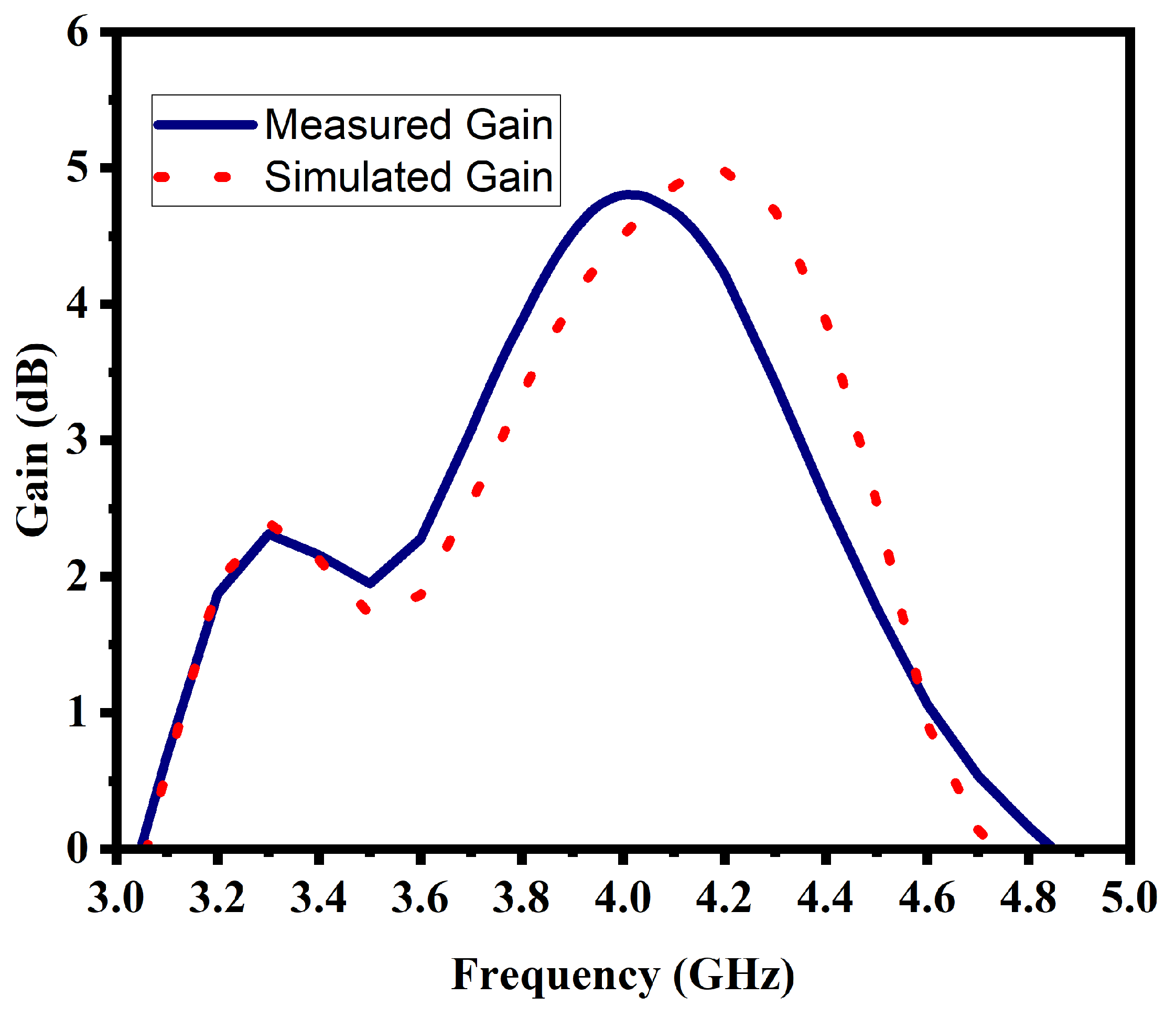
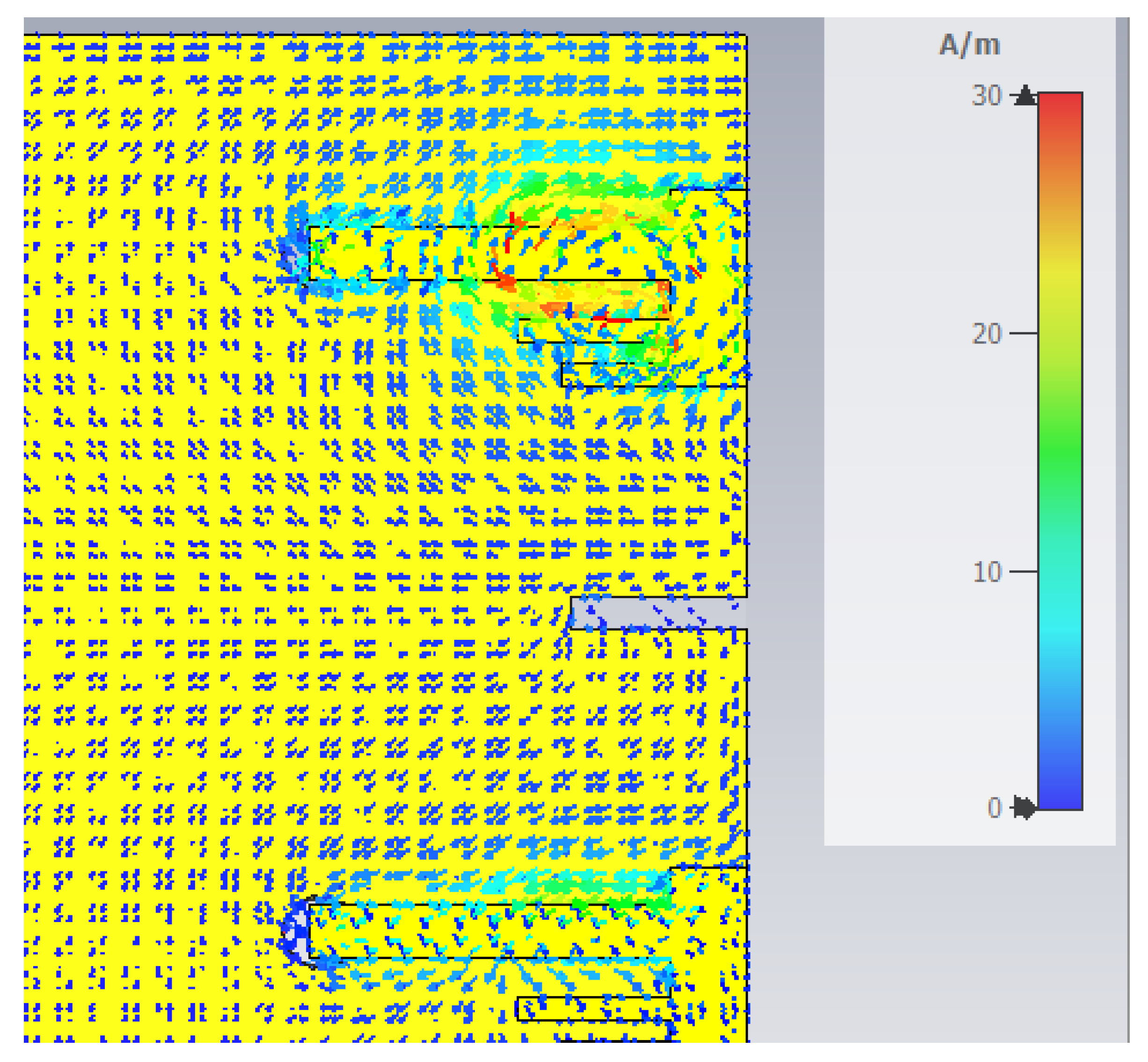
3.3. Gain of an Antenna and Current Distribution
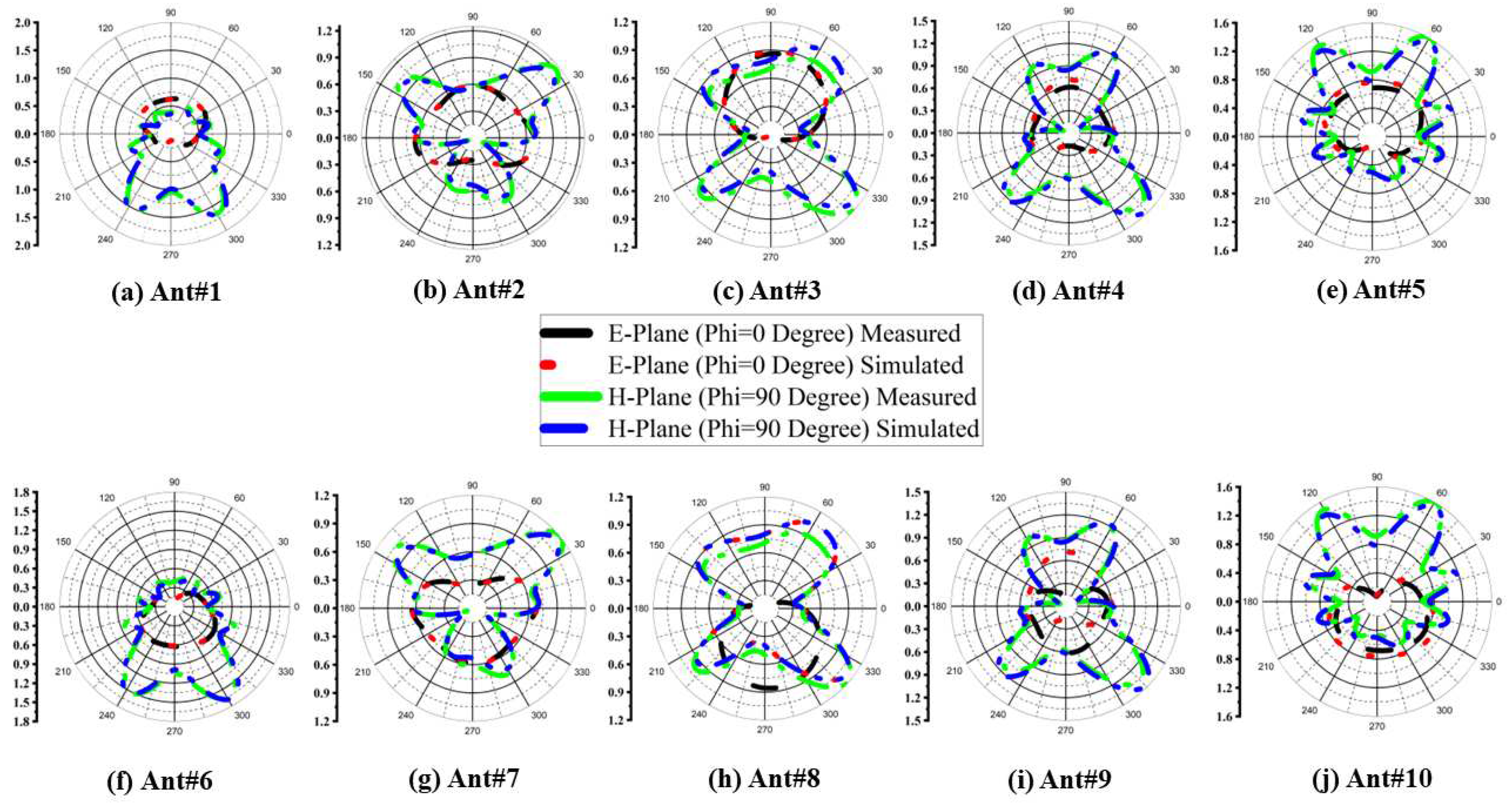
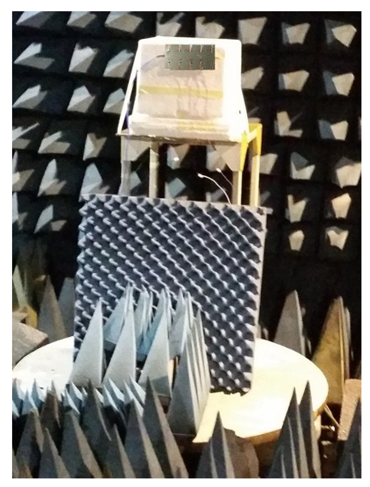
3.4. Radiation Pattern, Measurement Setup, and Comparison Table
4. Conclusion
References
- Elobied, A.A.; Yang, X.X.; Xie, N.; Gao, S. Dual-Band 2×2 MIMO Antenna with Compact Size and High Isolation Based on Half-Mode SIW. International Journal of Antennas and Propagation 2020, 2020, 2965767. [Google Scholar] [CrossRef]
- Zhang, S.; Zhao, K.; Ying, Z.; He, S. Adaptive Quad-Element Multi-Wideband Antenna Array for User-Effective LTE MIMO Mobile Terminals. IEEE Transactions on Antennas and Propagation 2013, 61, 4275–4283. [Google Scholar] [CrossRef]
- Liu, X.; Zhang, J.; Xi, H.; Yang, X.; Sun, L.; Gan, L. A Compact Four-band High-isolation Quad-port MIMO Antenna for 5G and WLAN Applications. AEU-International Journal of Electronics and Communications 2022, 154294. [Google Scholar] [CrossRef]
- Elfergani, I.; Hussaini, A.S.; Abd-Alhameed, R.; See, C.; Child, M.; Rodriguez, J. Design of a compact tuned antenna system for mobile MIMO applications. 2012. [Google Scholar] [CrossRef]
- Dong, J.; Wang, S.; Mo, J. Design of a Twelve-Port MIMO Antenna System for Multi- Mode 4G/5G Smartphone Applications Based on Characteristic Mode Analysis. IEEE Access 2020, 8, 90751–90759. [Google Scholar] [CrossRef]
- Li, Z.; Du, Z.; Takahashi, M.; Saito, K.; Ito, K. Reducing mutual coupling of MIMO antennas with parasitic elements for mobile terminals. IEEE Trans. Antennas Propag. 2012, 60, 473–481. [Google Scholar] [CrossRef]
- Li, M.; Jiang, L.; Yeung, K.L. A general and systematic method to design neutralization lines for isolation enhancement in MIMO antenna arrays. IEEE Trans. Vehicular Technol. 2020. [Google Scholar] [CrossRef]
- Ikram, M.; Sharawi, M.S.; Shamim, A.; Sebak, A. A multiband dual standard MIMO antenna system based on monopoles (4G) and connected slots (5G) for future smart phones. Microw. Opt. Technol. Lett. 2018, 60, 1468–1476. [Google Scholar] [CrossRef]
- Sun, Q.; Sun, B.; Sun, L.; Huang, W.; Ren, Q. Broadband two-element array with hybrid decoupling structures for multimode mobile terminals. IEEE Antennas Wireless Propag. Lett. 2015, 14, 1431–1434. [Google Scholar] [CrossRef]
- Dong, J.; Yu, X.; Deng, L. A decoupled multiband dual-antenna system for WWAN/LTE smartphone applications. IEEE Antennas Wireless Propag. Lett. 2017, 16, 1528–1532. [Google Scholar] [CrossRef]
- Yu, K.; Li, Y.; Liu, X. Mutual coupling reduction of a MIMO antenna array using 3D novel meta material structures. Appl. Comput. Electromagn. Soc. J. 2018, 33, 758–763. [Google Scholar]
- Li, M.-Y.; Ban, Y.-L.; Xu, Z.-Q.; Guo, J.; Yu, Z.-F. Tri-polarized 12-antenna MIMO array for future 5G smartphone applications. IEEE Access 2018, 6, 6160–6170. [Google Scholar] [CrossRef]
- Zhu, F.-G.; Xu, J.-D.; Xu, Q. Reduction of mutual coupling between closely-packed antenna elements using defected ground structure. Electron. Lett. 2012, 45, 601–602. [Google Scholar] [CrossRef]
- Suntives, A.; Abhari, R. Miniaturization and isolation improvement of a multiple-patch antenna system using electromagnetic bandgap structures. Microw. Opt. Technol. Lett. 2013, 55, 1609–1612. [Google Scholar] [CrossRef]
- Adamiuk, G.; Beer, S.; Wiesbeck, W.; Zwick, T. Dual-orthogonal polarized antenna for UWB-IR technology. IEEE Antennas Wireless Propag. Lett. 2009, 8, 981–984. [Google Scholar] [CrossRef]
- Iqbal, A.; Saraereh, O.A.; Ahmad, A.W.; Bashir, S. Mutual coupling reduction using F-shaped stubs in UWB-MIMO antenna. IEEE Access 2017, 6, 2755–22759. [Google Scholar] [CrossRef]
- Pandit, S.; Mohan, A.; Ray, P. A compact planar MIMO monopole antenna with reduced mutual coupling for WLAN applications using ELC resonator. In Proceedings of the IEEE Microw. Conf. (APMC); 2016; pp. 1–4. [Google Scholar]
- Verma, A.K.; Nakkeeran, R.; Vardhan, R.K. Design of 2x2 single-sided wrench-shaped UWB MIMO antenna with high isolation. In Proceedings of the IEEE Int. Conf. Circuit, Power Comput. Technol. (ICCPCT); 2016; pp. 1–3. [Google Scholar]
- Cui, L.; Guo, J.; Liu, Y.; Sim, C. An 8-element dual-band MIMO antenna with decoupling stub for 5G smartphone applications. IEEE Antennas and Wireless Propagation Letters 2019, 18, 2095–2099. [Google Scholar] [CrossRef]
- Li, Y.; Sim, C.; Luo, Y.; Yang, G. High isolation 3.5 GHz eight antenna MIMO array using balanced open-slot antenna element for 5G smartphones. IEEE Transactions on Antenna and Propagation 2019, 67, 3820–3830. [Google Scholar] [CrossRef]
- Malathi, A.C.; Thiripurasundari, D. Compact 2×1 MIMO Antenna System for LTE Band. Progress In Electromagnetics Research C 2017, 75, 63–73. [Google Scholar] [CrossRef]
- Alexa, F.; Bardeanu, B.; Vatau, D. MIMO antenna system for LTE. In Proceedings of the 2013 36th International Conference on Telecommunications and Signal Processing (TSP); 2013; pp. 294–298. [Google Scholar] [CrossRef]
- Qualcomm. Making the Best Use of Licensed and Unlicensed Spectrum. [Online]. 2015. Available online: https://www.qualcomm.com/media/documents/files/making-the-best-use-of-unlicensed-spectrumpresentation.pdf.
- IMT-2020 (5G) Promotion Group. White Paper on 5G Concept. [Online]. 2015. Available online: http://www.imt-2020.org.cn/zh/documents/download/4.
- SK Telecom. SK Telecom 5G White Paper.[Online]. 2014. Available online: http://www.sktelecom.com/img/pds/press/SKT-5G%20White%20Paper_V1.0_Eng.pdf.
- Arunraj, M.; Mathivadhani, A.; Deepa, D.; Kumar, S.A. Design of F shaped MIMO antenna for WIMAX Applications. In Proceedings of the 2019 Third International Conference on Inventive Systems and Control (ICISC), Coimbatore, India; 2019; pp. 159–161. [Google Scholar] [CrossRef]
- Yuan, X.-T.; Chen, Z.; Gu, T.; Yuan, T. A Wideband PIFA-Pair-Based MIMO Antenna for 5G Smartphones. IEEE Antennas and Wireless Propagation Letters 2021, 20, 371–375. [Google Scholar] [CrossRef]
- Kumar, D.R.; Babu, G.V.; Narayan, K.G.S. Compact F-Shaped Antenna with its Analytical Modelling Resonating at 3.5 GHz for 5G Applications. In Proceedings of the 2021 IEEE Indian Conference on Antennas and Propagation (InCAP); 2021; pp. 01–04. [Google Scholar] [CrossRef]
- Parchin, N.O.; et al. Modified PIFA Array Design with Improved Bandwidth and Isolation for 5G Mobile Handsets. In Proceedings of the 2019 IEEE 2nd 5G World Forum (5GWF), Dresden, Germany; 2019; pp. 199–203. [Google Scholar] [CrossRef]
- Sharawi, M.S. Printed Multi-Band MIMO Antenna Systems and Their Performance Metrics [Wireless Corner]. IEEE Antennas and Propagation Magazine 2013, 55, 218–232. [Google Scholar] [CrossRef]
- Li, Y.; Sim, C.-Y.-D.; Luo, Y.; Yang, G. 12-Port 5G Massive MIMO Antenna Array in Sub-6GHz Mobile Handset for LTE Bands 42/43/46 Applications. IEEE Access 2018, 6, 344–354. [Google Scholar] [CrossRef]
- Zou, H.; Li, Y.; Sim, C.-Y.-D.; Yang, G. Design of 8 × 8 dual-band MIMO antenna array for 5G smartphone applications. Int. J. RF Microw. Comput.-Aided Eng. 2018, 28, e21420. [Google Scholar] [CrossRef]
- Guo, J.L.; Cui, L.; Li, C.; Sun, B.H. Side-edge frame printed eight-port dual-band antenna array for 5G smartphone applications. IEEE Trans. Antennas Propag. 2018, 66, 7412–7417. [Google Scholar] [CrossRef]
- Li, Y.; Sim, C.-Y.-D.; Luo, Y.; Yang, G. Metal-frame-integrated eight-element multiple-input multiple-output antenna array in the long term evolution bands 41/42/43 for fifth generation smartphones. Int. J. RF Microw. Comput.-Aided Eng. 2019, 29, e21495. [Google Scholar] [CrossRef]
- Wang, H.; Zhang, R.; Luo, Y.; Yang, G. Compact eight-element antenna array for triple-band MIMO operation in 5G mobile terminals. IEEE Access 2020, 8, 19433–19449. [Google Scholar] [CrossRef]
- Li, Y.; Sim, C.-Y.-D.; Luo, Y.; Yang, G. 12-port 5G massive MIMO antenna array in sub-6 GHz mobile handset for LTE bands 42/43/46 applications. IEEE Access 2017, 6, 344–354. [Google Scholar] [CrossRef]
- Jaglan, N.; Gupta, S.D.; Sharawi, M.S. 18 element massive MIMO/diversity 5G smartphones antenna design for sub-6 GHz LTE bands 42/43 applications. IEEE Open J. Antennas Propag. 2021, 2, 533–545. [Google Scholar] [CrossRef]
- Huang, J.; Dong, G.; Cai, J.; Li, H.; Liu, G. A quad-port dualband MIMO antenna array for 5G smartphone applications. Electronics 2021, 10, 542. [Google Scholar] [CrossRef]
- Huang, J.; Dong, G.; Cai, Q.; Chen, Z.; Li, L.; Liu, G. Dual-band MIMO antenna for 5G/WLAN mobile terminals. Micromachines 2021, 12, 489. [Google Scholar] [CrossRef]
- Serghiou, D.; Khalily, M.; Singh, V.; Araghi, A.; Tafazolli, R. Sub-6 GHz dual-band 8 × 8 MIMO antenna for 5G smartphones. IEEE Antennas Wireless Propag. Lett. 2020, 19, 1546–1550. [Google Scholar] [CrossRef]
- Cui, L.; Guo, J.; Liu, Y.; Sim, C.-Y.-D. An 8-element dual-band MIMO antenna with decoupling stub for 5G smartphone applications. IEEE Antennas Wireless Propag. Lett. 2019, 18, 2095–2099. [Google Scholar] [CrossRef]
- Ahmed, M.; Zafar, Z.; Javed, I.; Zahid, M.; Amin, Y. 12 Element Inverted E-Shaped Massive MIMO Antennas for Future 5G Smartphone Applications. In Proceedings of the 2023 7th International Multi-Topic ICT Conference (IMTIC), Jamshoro, Pakistan; 2023; pp. 1–5. [Google Scholar] [CrossRef]
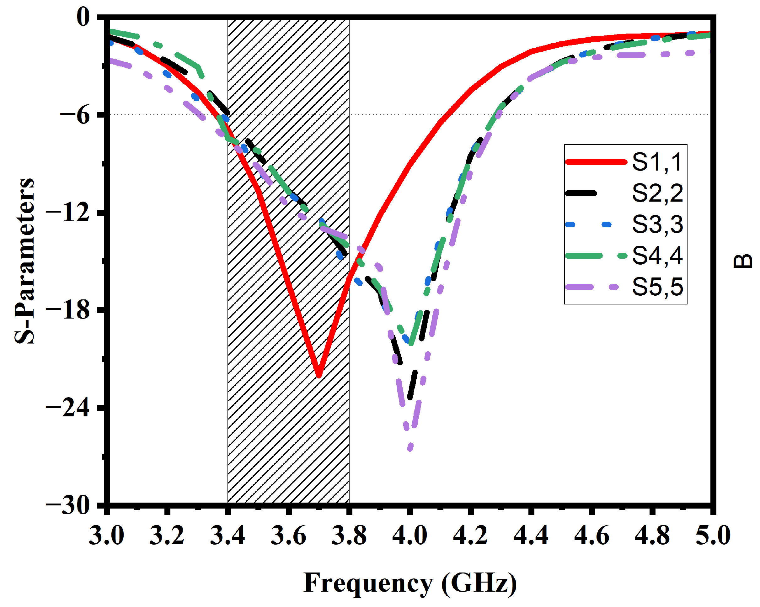
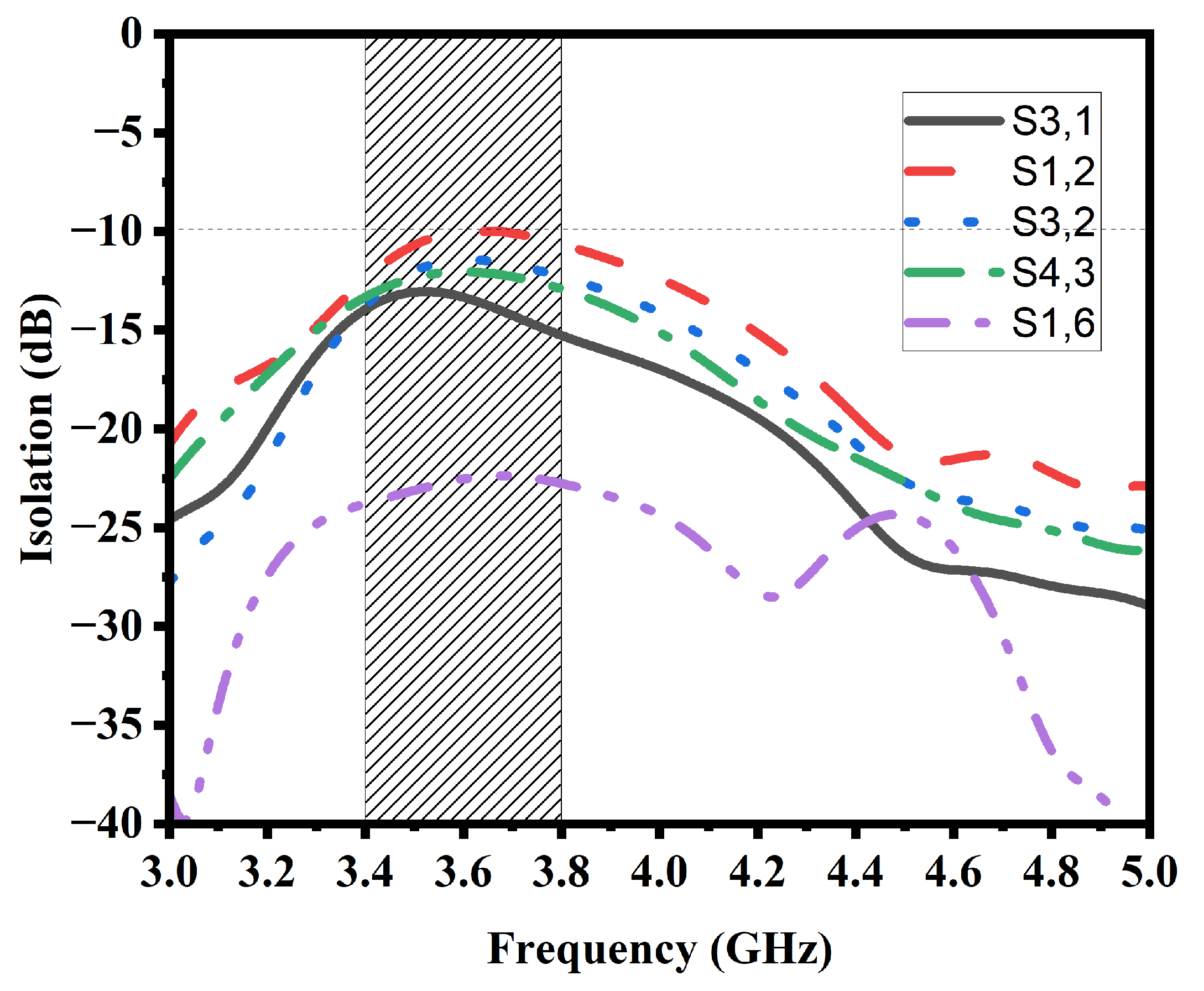
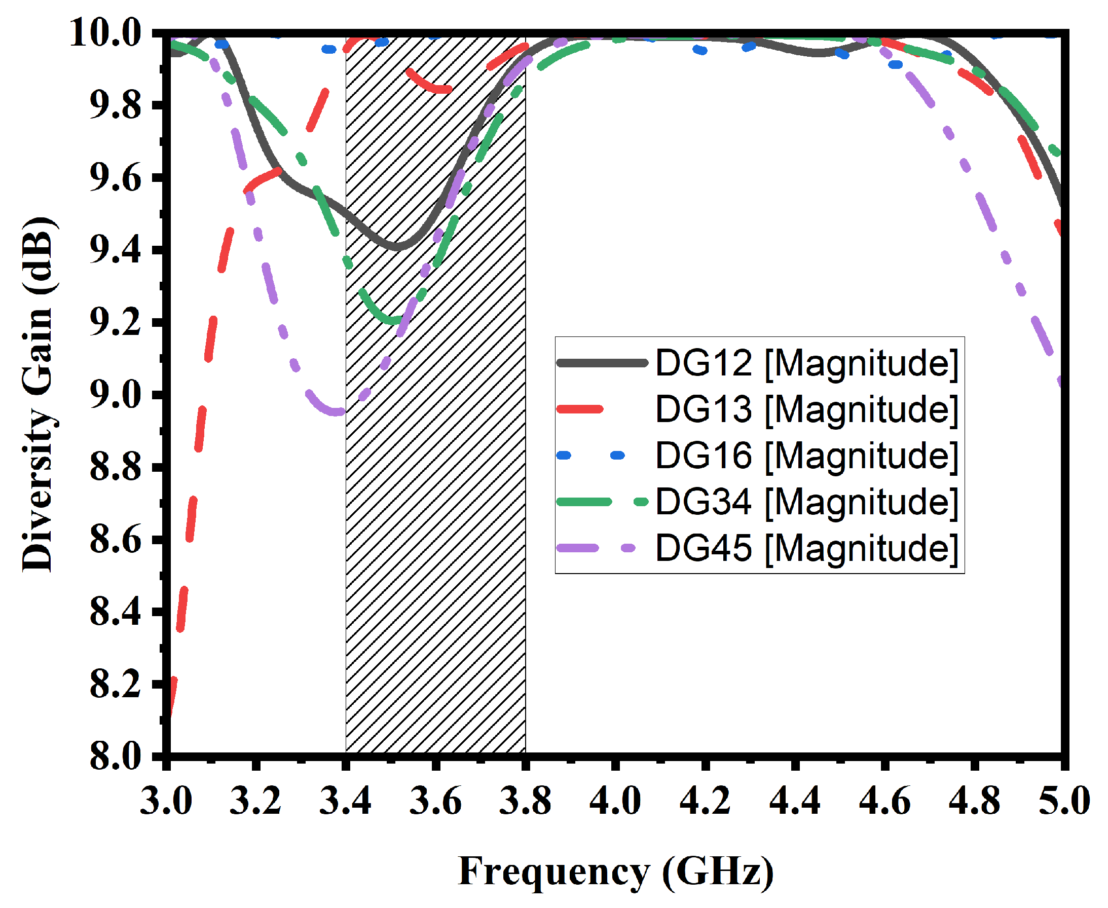
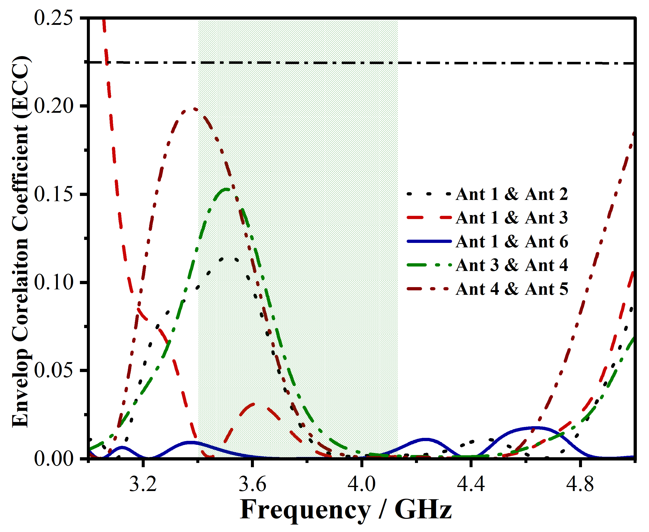
| Ref. No. | Dimension () | Resonance Freq. (GHz) | Bandwidth (MHz) | Gain (dBi) |
|---|---|---|---|---|
| [26] | 31×28 | 3.5 | 1350 | 4.5 |
| [27] | 15×6.2 | 4.5 | 2000 | not mentioned |
| [28] | 19.3×6.2 | 3.5 | 250 | not mentioned |
| [29] | 26×12 | 3.55 | 600 | not mentioned |
| Proposed | 20×9 | 3.6 | 700 | 5.1 |
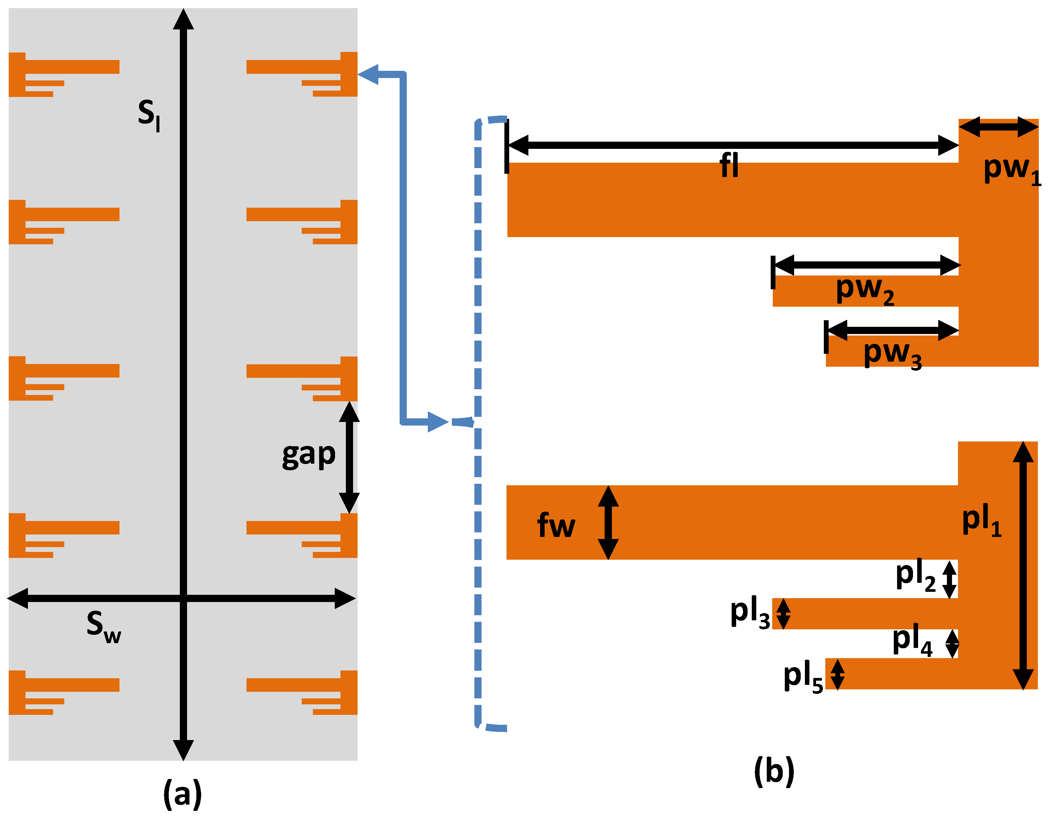
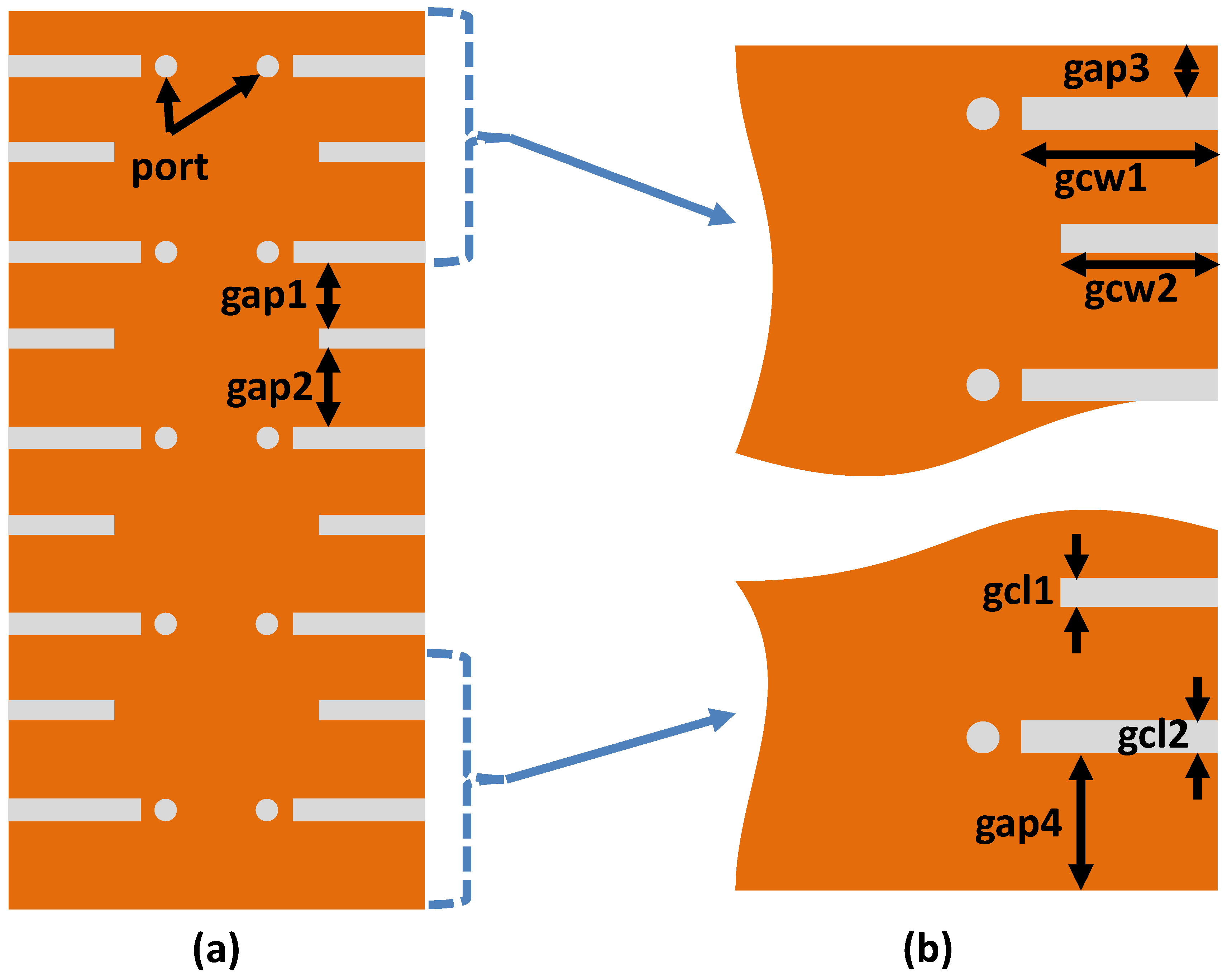
| Parameter | Value () | Parameter | Value () | Parameter | Value () |
|---|---|---|---|---|---|
| 150 | 70 | gap | 22 | ||
| fl | 16.5 | fw | 2.43 | 3.5 | |
| 7 | 5 | 9 | |||
| 1.785 | 1 | 1 | |||
| 1 | gap1 | 12.8 | gap2 | 15 | |
| gap3 | 9.15 | gap4 | 15.15 | gcw1 | 9.99 |
| gcw2 | 8 | gcl1 | 1.5 | 1.7 |
| Reference | Bandwidth (GHz) | Isolation (-dB) | ECC | Total Efficiency (%) | Radiator size in () | Impedance Bandwidth (%) | Peak Channel Capacity () |
|---|---|---|---|---|---|---|---|
| [Proposed] | 3.4-3.6, 3.6-3.8 (-6dB) | >10 | <0.19 | >67 | 0.17 × 0.05 × 0.01 | 19.9 | 45 (10 × 10) |
| [32] | 3.4-3.6, 5.15-5.92 (-6dB) | >12 | <0.1 | >50 | 0.17 × 0.05 × 0.01 | 19.71 | 38.8 (8 × 8) |
| [33] | 3.4-3.6, 4.8-5.1 (-6dB) | >12 | <0.1 | 40-85 | 0.17 × 0.03 × 0.01 | 11.77 | 38.5 (8 × 8) |
| [34] | 2.49-2.69, 3.4-3.8 (-6dB) | >10.5 | <0.2 | 44-66 | 0.02 × 0.17 × 0.01 | 18.59 | 38.3 (8 × 8) |
| [35] | 3.35-3.82, 4.79-6.2 (-6dB) | >10.5 | <0.12 | >43 | 0.17 × 0.03 × 0.01 | 41.77 | 37.6 (8 × 8) |
| [36] | 3.4-3.8, 5.15-5.92 (-6dB) | >12 | <0.15 | 41-79 | 0.13 × 0.04 × 0.01 | 25.11 | 29.5 (6 × 6) |
| [37] | 3.4-3.6, 3.6-3.8 (-10dB) | >20 | <0.01 | >87 | 0.11 × 0.04 × 0.02 | 11.11 | 81 (18 × 18) |
| [38] | 3.4-3.6, 4.8-5 (-10dB) | >16.5 | <0.01 | 82-85 | 0.16 × 0.07 × 0.01 | 9.79 | Not Mentioned (4 × 4) |
| [39] | 3.3-3.8, 4.8-5, 5.15-5.35, 5.72-5.85 (-10dB) | >15 | <0.02 | >70 | 0.16 × 0.07 × 0.01 | 24.02 | Not Mentioned (4 × 4) |
| [40] | 3.1-3.85, 4.8-6 (-10dB) | >17 | <0.06 | 65-71 | 0.20 × 0.05 × 0.01 | 36.17 | 39 (8 × 8) |
| [41] | 3.3-4.2, 4.8-5.0 (-6dB) | >10 | <0.12 | 53.8-79.1 | 0.21 × 0.07 × 0.01 | 28.10 | 39.5 (8 × 8) |
| [42] | 2-2.4, 5.8-6.1 (-6dB) | >48 | <0.12 | 70-84 | 0.24 × 0.108 × 0.001 | 15.38 | 39.5 (12 × 12) |
Disclaimer/Publisher’s Note: The statements, opinions and data contained in all publications are solely those of the individual author(s) and contributor(s) and not of MDPI and/or the editor(s). MDPI and/or the editor(s) disclaim responsibility for any injury to people or property resulting from any ideas, methods, instructions or products referred to in the content. |
© 2023 by the authors. Licensee MDPI, Basel, Switzerland. This article is an open access article distributed under the terms and conditions of the Creative Commons Attribution (CC BY) license (http://creativecommons.org/licenses/by/4.0/).


