1. Introduction
Drones are a type of unmanned aircraft achieving significant attention in recent years for both civilian and commercial applications due to their hovering capability, flight capacity, ease of deployment, low operation and maintenance costs. Drones have many use cases since it has been used in a wide range of applications such as disaster rescue operations, smart agriculture, emergency medical services, and aerial photography [
1]. In addition, recent advances in drone technology have made it possible to widely deploy drones for wireless communication. This allows drones to be used as aerial base stations to support the connection of existing terrestrial wireless networks such as cell phones and broadband networks.
Unlike conventional ground base stations, aerial base stations have the advantage that they can adjust their flight altitude and avoid obstacles to increase the possibility of connecting with ground users by establishing LoS (Line-of-Sight). The LoS connection can improve coverage and data rate performance. In addition, it is possible to construct the network flexibly because it can be freely deployed in the air. On the other hand, wireless data communication has exploded in the last few years due to the rapid spread of the IoT (Internet of Things) and their various new applications. However, conventional wireless drone networks operate in the microwave frequency band below 6 GHz, where the spectrum resources are already heavily utilized. Despite the rapid increase in the demand for data capacity, there is a growing concern that the available spectrum is limited. Several techniques have been proposed to improve the network capacity and to achieve high frequency efficiency in future cellular systems. For example, MIMO (Multiple-Input and Multiple-Output), NOMA (Non-Orthogonal Multiple Access), and cooperative relaying. However, these technological advances do not provide a solution to solve the spectrum scarcity problem. Therefore, a solution may be to expand using higher frequencies in the radio spectrum. In this paper, communication links between user and drone, and between drone and drone are considered using millimeter wave communication. The expanding in using millimeter-wave frequencies can provide multiple gigabit data transmission rates by ensuring a wide range of available spectrum resources [
2]. Hence, millimeter-wave communication should be leveraged in 5G wireless communication systems that requires very high data throughput, wide bandwidth, high communication speed, and low latency. In addition to the sufficient bandwidth, the short wavelength of millimeter-wave communication makes it possible to design physically small circuits and antennas. Moreover, it is easy to achieve sharper directivity by miniaturizing the antenna. On the other hand, millimeter wave communications suffer from large free space attenuation. In addition to the expected application of drone to wireless networks, the possibility of transmitting multiple gigabits of data using 5G millimeter-wave communications has led to the idea of combining wireless network support by drone with millimeter-wave communications [
3].
In this paper, we propose a scenario for a disaster area where ground base stations are out of service. In fact, during the Great East Japan Earthquake in 2011, about 29,000 cell phone base stations and PHS (Personal Handy-phone System) base stations of five major companies, NTT docomo, KDDI, Softbank Mobile, EMOBILE, and WILLCOM, were out of service [
4]. The first 72 hours after a disaster occurs are considered the most critical, and it is necessary to deploy wireless networks quickly to restore communication connectivity in order to aid rescue teams in the disaster area. Establishing a wireless network using drones in the damaged area where ground base stations are malfunctioned is an effective and fast method to support different rescue operations at the disaster area. One of the current problems is that when multiple drones communicate with the user, the UL (uplink) that sends data from the user to the aerial base station and the DL (downlink) that sends data from the aerial base station to the user cause interference. In this paper, we investigate the improvement of SIR by using the characteristics of circular polarization whose rotation direction changes before and after the ground reflection. For the propagation model, we apply the two-ray model to calculate the received power and SIR, and show the effectiveness of the proposed method. This paper extends from the authors’ previous work in [
5], where only a system of access drones communicating directly to ground users was investigated. In this paper, we thoroughly investigate the overall system under the existence of backhaul drones that cause more intra/inter-system interference.
Figure 1.
Overall architecture.
Figure 1.
Overall architecture.
The rest of this paper is organized as follows. In
Section 2, we present the related work about our research and the overall architecture of our research. In
Section 3, we show the system model and design using different antenna polarization when there are only access drones and ground users.
Section 4 furthermore investigates the SIR performance of the system when there is the existence of backhaul drones. Finally,
Section 5 concludes the findings of the paper and our future works are described.
2. Related Works
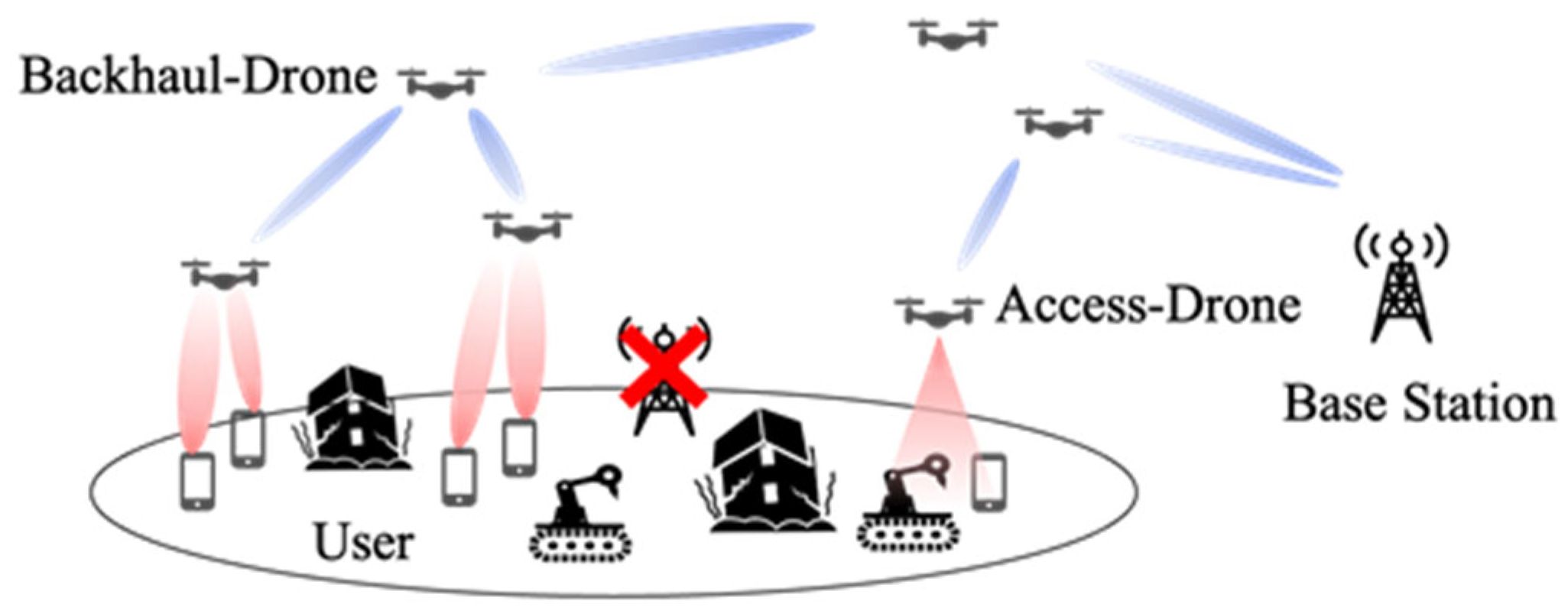
The overall architecture of this research is shown in
Figure 1. The roles of drones are assumed to be divided into the access-drones and the backhaul-drones to provide data to users. The access-drones communicates directly with the user, while the backhaul-drones acts as a relay between the access-drones and the ground base station. By relaying the backhaul-drones, the communication distance between drones becomes shorter. This reduces the effect of distance attenuation and rainfall attenuation, which are concerns in millimeter-wave communication. On the other hand, since the access-drones provide data directly to users, it is important to know how to deploy these drones. If drones are efficiently deployed, it is expected to provide LoS communication to the ground users, which is important in millimeter-wave communications, and to expand the coverage with fewer base stations.
Authors in [
6] show the minimum transmit power required to have a certain coverage radius as a function of the altitude of the drones. At lower altitudes, the shadowing effect reduces the probability of LoS connection between the transmitter and the receiver, resulting in a decrease in the coverage radius. On the other hand, at high altitudes, the probability of LoS connection is high. However, due to the large distance between the transmitter and the receiver, the path loss increases and as a result, the coverage performance decreases. In [
7], the optimal deployment of multiple drones equipped with directional antennas as aerial base stations is investigated. Based on the circle packing theory, an efficient placement method is proposed in which each drone can obtain the maximum coverage with the minimum transmission power. As a result, the optimal altitude and position of drones are determined based on the number of available drones, antenna gain and beam-width. In [
8], a deployment method that combines the K-means method with the minimum envelope problem is considered to maximize the data rate that can be provided to users in DL. There have been many studies of deployment methods that give priority to DL connections, but few studies have been conducted in environments where DL and UL concurrently exist. In this paper, we propose a method to reduce the interference to UL caused by DL in the communication between an access-drone and a user.
3. Access Link Analysis
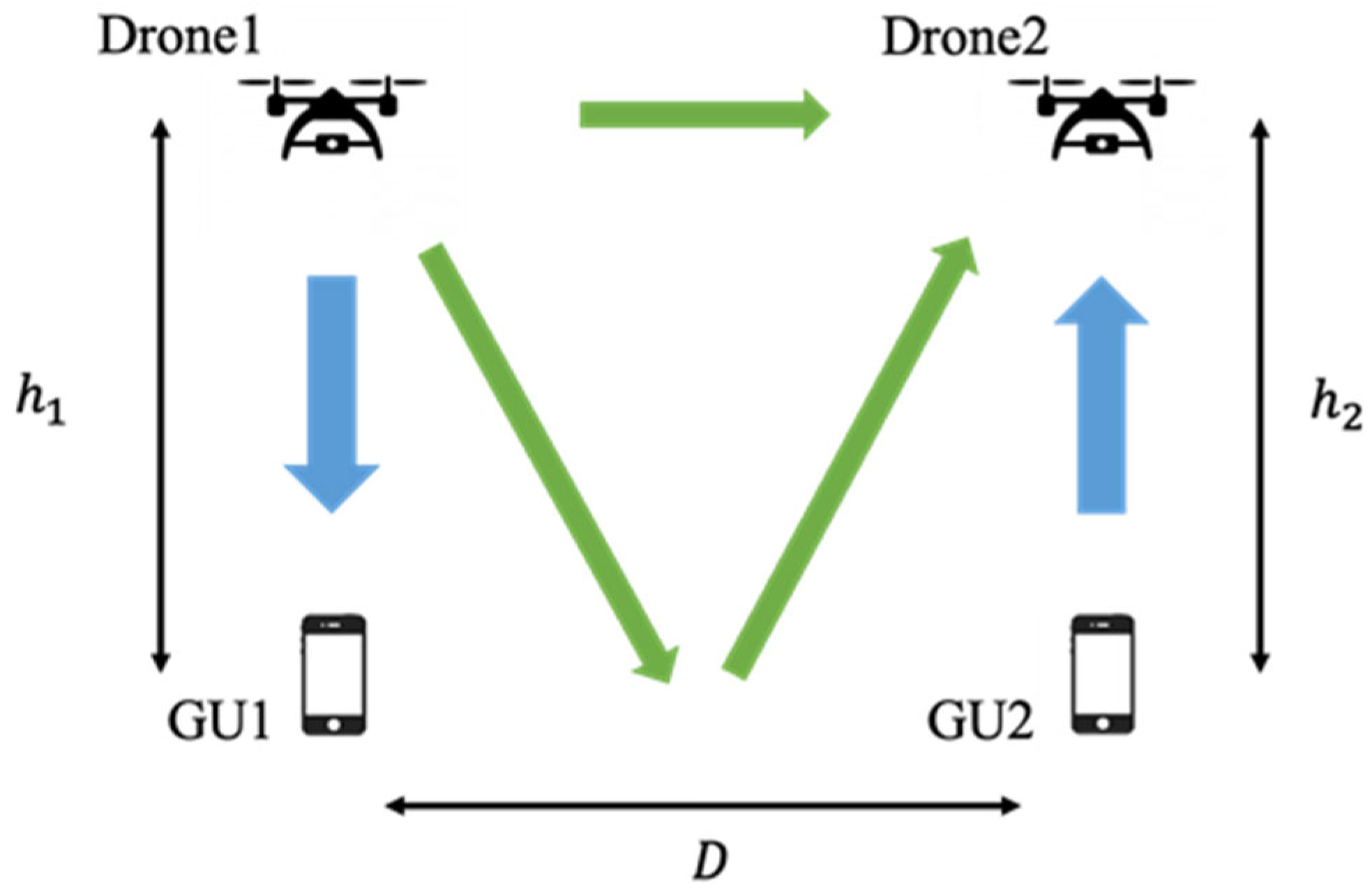
In this section, we describe the system model and the proposed method considered in this research. For simplicity, we consider an UL-DL pair system as shown in
Figure 2. The structure of this section is as follows.
Section 3.1 describes the overall system model with the considered arrangement of the drone and the user. In
Section 3.2, the analysis is applied for conventional cases when drones employ linearly polarized antennas. In
Section 3.3, the analysis is applied for our proposed system design when drones are proposed to be equipped with circularly polarized antennas.
3.1. System Model
Figure 2 shows the system model used in this research. Here,
is the height of Drone 1 from the ground surface,
is the height of Drone 2 from the ground surface, and
is the distance between Drone 1 and Drone 2 (GU1 and GU2). The blue arrow represents the desired signal, the green one represents the interference signal. We considered an environment in which the user and the drone are communicating one-to-one. The communication between Drone 1 and GU1 is assumed to be DL, and that between Drone 2 and GU2 is assumed to be UL. It is assumed that the communication between Drone 1-GU1 and Drone 2-GU2 is DL and that the communication between Drone 1-GU1 and Drone 2-GU2 is UL. Considering the receiving power of Drone 2, the signal transmitted from GU2 can be treated as a desired signal, and the other signals are treated as interference signals. During the communication between Drone 1 and GU1, a part of the radio wave transmitted from Drone 1 is reflected from the ground and is received by Drone 2 as an interference component. It is considered that the shorter
is, the larger the influence of the ground reflection. The direct wave from Drone 1 without ground reflection is also received by Drone 2 as an interference component.
3.2. Linearly Polarized Antenna Case
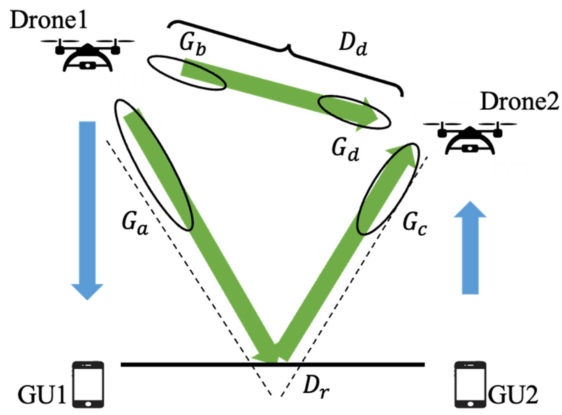
In this section, we apply the two-ray model to the system model described in Sect 3.1, and calculate the received power and SIR from Friis's formula. The received signal in Drone 2 consists of two components, i.e. the direct wave transmitted from Drone 1 through free space and the reflected wave from the ground. The distance of the direct wave and the reflected wave is shown as follows.
The phase difference
between the direct wave and the reflected wave is shown as follows.
The received power, which is the interference signal at Drone 2, is shown as follows by applying the two-ray model as shown in
Figure 3.
where
denotes the transmit power of Drone 1,
denotes the reflection coefficient,
denotes the product of the antenna field patterns along the LoS direction,
denotes the product of the antenna field patterns along the reflected path. The antenna model is based on the following equation.
where
denotes the half-width angle,
denotes the main lobe width,
denotes the antenna gain.
The power of the desired signal transmitted from GU2 is shown as follows.
where
denotes the terminal ground power,
denotes the terminal antenna gain. From the above, SIR can be shown as follows.
where
denotes the desired power received from GU2 to Drone 2 and
denotes the interference power received from Drone 1 to Drone 2.
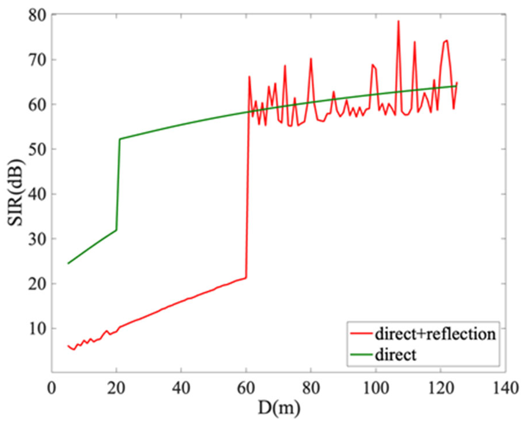
Figure 4 shows the SIR when
is varied from 5m to 125m in the system model with
=50m and
=25m. The green curve shows the SIR of the direct wave only, and the red curve shows the SIR of the two-ray model that combines the direct and reflected waves. From the figure, we can see that the red curve is less than 30dB for the range from 5m to 60m, which is affected by the ground reflection. The closer the distance between the drones is, the stronger the interference becomes, and the more remarkably SIR performance degrades. Therefore, it is necessary to improve the SIR performance for this target communication range. Under the same conditions, the proposed method investigates the usage of circular polarization to resolve the aforementioned issue as shown in the next section.
Figure 4.
SIR performance with linearly polarized antenna.
Figure 4.
SIR performance with linearly polarized antenna.
3.3. Circularly Polarized Antenna Case
In the system model shown in
Figure 2, we considered the adoption of circular polarization. A circular polarization wave is a polarized wave in which the electric field propagates in a rotation like a circle. There are two advantages of using the circular polarization. The first is that the alignment angle of the transmitting and receiving antennas in the wave-front can be set freely because the electric field component propagates in a rotating pattern. The second is that the direction of rotation of the electric field after reflection can be reversed if the angle of incidence of the electric field is within the Brewster angle, thereby reducing multipath fading [
9]. In our system model shown in
Figure 2, Drone 1 and Drone 2 are equipped with antennas that can transmit and receive right-handed circular polarization, and GU1 and GU2 are equipped with antennas that can transmit and receive linearly polarized waves. The right-handed circular polarization transmitted from Drone 1 is converted to left-handed circular polarization after reflection from the ground, and Drone 2, which is equipped with an antenna capable of receiving right-handed circular polarization, cannot receive the left-handed circular polarization. With this principle, we considered how to improve the SIR of Drone 2 by preventing the influence of ground reflection. On the other hand, it should be noted that the desired signal transmitted from GU2 is linearly polarized waves, so the power is only half when it is received by Drone 2. Next, we apply the circular polarization to the system model and explain how to calculate the electric field after reflection. The polarization plane that is vertical to the ground is called a vertical polarization (TM wave), and that that is horizontal is called a horizontal polarization (TE wave). The reflection coefficients for incident vertical and horizontal polarization waves are shown as follows.
where
denotes the relative dielectric constant of the earth fields,
denotes conductivity,
denotes the dielectric constant of free space,
denotes grazing angle, where
is defined as follows.
The reflection coefficient is determined by the shape and material of the ground and is expressed as a complex number. In our research, we adopted the value for an average ground in [
10]. Assuming that the wave propagates in the z-axis direction, the right-handed circular polarization can be expressed as follows.
When the phase is 90° behind, the circular polarization is right-handed, and when the phase is 90° ahead, the circular polarization is left-handed. Since the circular polarization can be decomposed into TM wave and TE wave, the electric field of TM wave and TE wave can be shown as follows.
where
denotes amplitude of electric field,
denotes the unit vector in x-axis direction,
denotes the unit vector in y-axis direction,
denotes a wave number,
denotes the speed of light.
Based on the reflection coefficient and the incident wave, the TM and TE waves after ground reflection are expressed as follows.
where
denotes TM wave before reflection,
denotes TE wave before reflection,
denotes TM wave after reflection,
denotes TE wave after reflection.
By matrix calculation, the right- and left-handed circular polarization after ground reflection are shown as follows.
(20)
where
denotes left-handed circular polarization,
denotes right-handed circular polarization.
The desired power to be received from GU2 to Drone 2 is shown as follows.
where
denotes the amplitude of linear polarization,
denotes the transmit power of the terminal,
denotes the gain of receiving antenna (Drone 2). The reason for the factor of a half in Eq. (21) is that a circularly polarized antenna can receive only half the power of a linearly polarized transmission. The power is calculated as the square of the absolute value of the electric field.
Table 1.
Numerical parameters.
Table 1.
Numerical parameters.
| Parameter |
Value[Unit] |
| Carrier Frequency |
28[GHz] |
| Bandwidth |
100[MHz] |
| Transmit Power(drone) |
13[dBm] |
| Transmit Power(terminal) |
23[dBm] |
| Transmit Antenna half-width |
30[] |
| Receive Antenna gain |
0[dBi] |
| Conductivity |
|
| Relative dielectric constant |
15 |
3.4. Numerical Analysis
Numerical analyses are conducted to evaluate the SIR of the conventional and proposed UAV’s antennas. The parameters used in our numerical analyses are listed in the
Table 1.
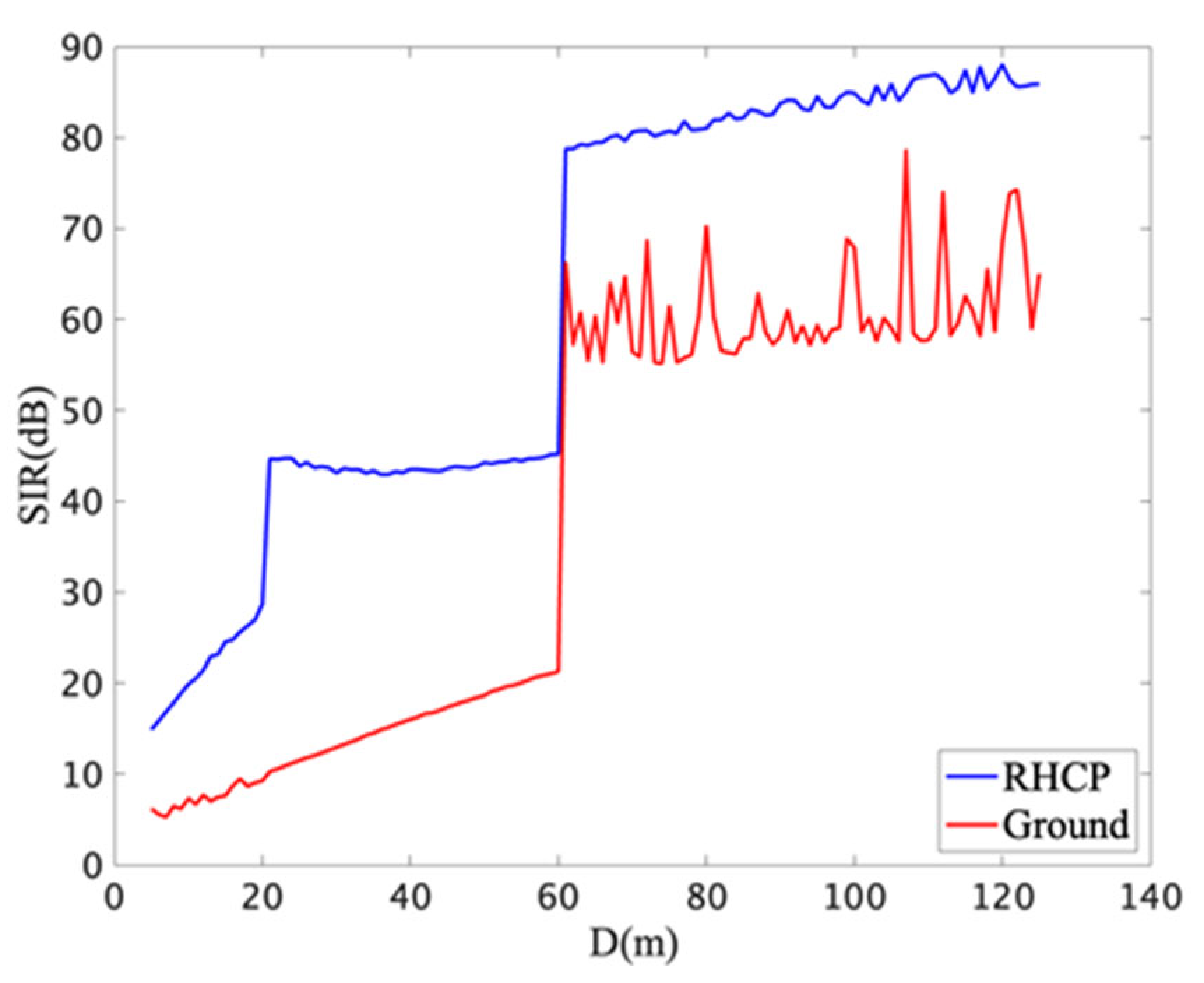
Figure 5 shows the SIR of the system with
=50m and
=25m while
is varied from 5m to 125m.
Figure 5.
SIR performance with circularly polarized antenna.
Figure 5.
SIR performance with circularly polarized antenna.
The blue curve shows the SIR of the right-handed circular polarization transmitted from Drone 1. The red curve is the same curve as
Figure 4 and is shown for the sake of comparison. The SIR is less than 20dB when circularly polarized antenna is not applied for the range 20m and 60m, which is affected by the ground reflection. On the other hand, the SIR of more than 40dB can be achieved in the case of circular polarization. However, when the distance between the users is closer, e.g. from 5 m to 20 m, the SIR is less than 30 dB even in the case of circular polarization. The reason for this phenomenon is that Drone 2 is placed within the main lobe of Drone 1's antenna. In order to improve the SIR in these specific distance ranges, it is preferred to introduce antennas of narrower beam-width. When the separation of the drones is more than 60m, we can see a significant increase in the SIR. This is owing to the fact that the reflected wave is received with side lobes at the receiver.
4. Backhaul Link Analysis
In this section, the system model in
Section 3 is further extended to the scenarios with the existence of backhaul drones.
Section 4.1 describes the extended system model with the existence of backhaul drones. In
Section 4.2, the SIR performance at the access drones is evaluated. Furthermore,
Section 4.3 evaluates the SIR performance at the backhaul drones.
4.1. System Model
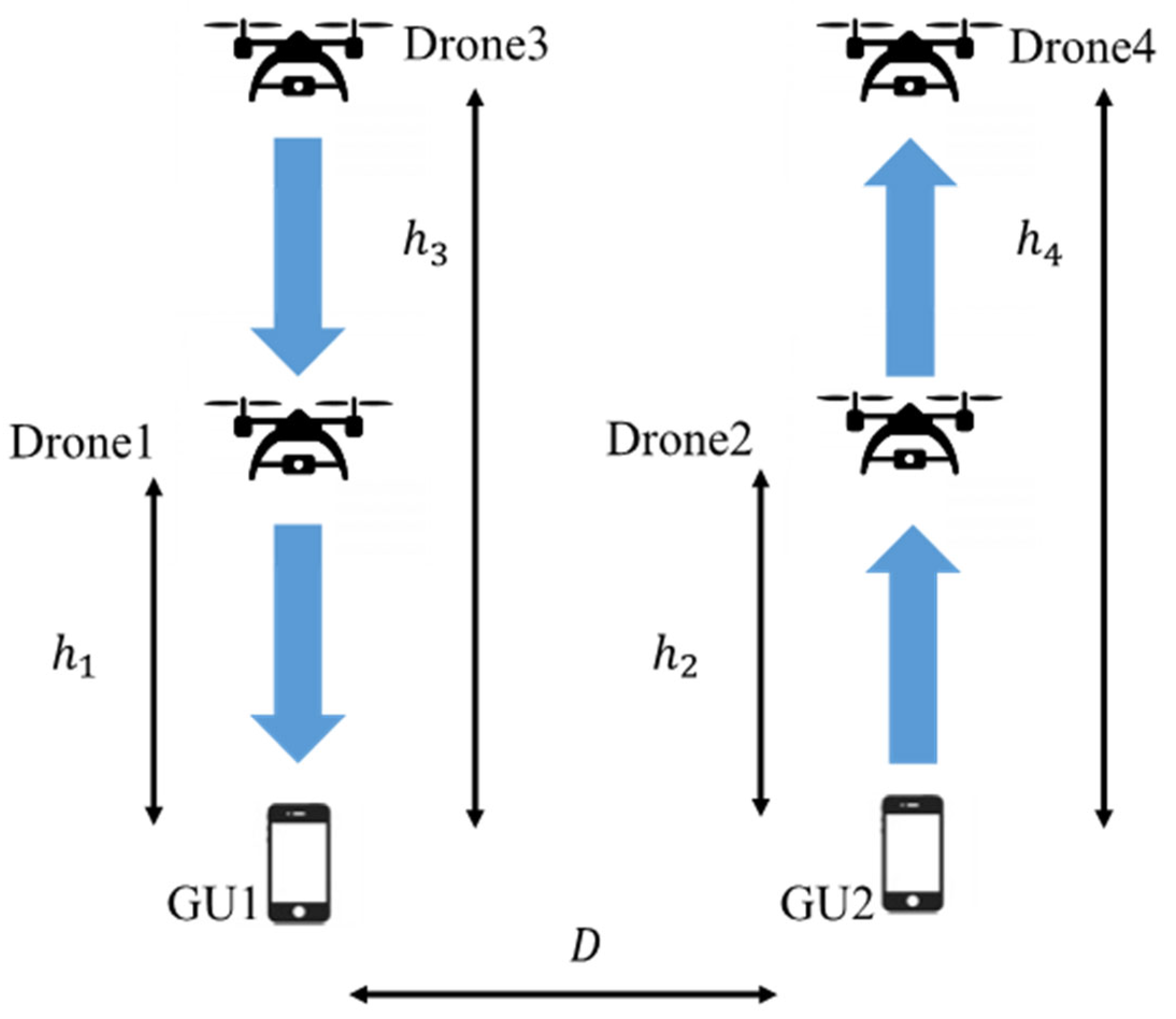
A system model with backhaul drones is shown in
Figure 6. In this system, a backhaul drone Drone3 is placed on top of the access drone Drone1 providing DL services to the user GU1. Similarly, a backhaul drone Drone4 is placed above the access drone Drone2 providing UL services to the user GU2. Let
be the height of the backhaul drone Drone3, and
be the height of the backhaul drone Drone4 respectively. Focusing on Drone2, the desired signal is the signal transmitted from GU2, and the signals received from other sources are interference signals. Similarly, the desired signal for Drone4 is the signal transmitted from Drone2, and the signals received from other drones are interference signals. The access drone plays the role of a Decode-and-Forward (DF) relay station that transferring DL or UL data between the ground user and the backhaul drone. For that purpose, each access drone is assumed to be equipped with two antenna interfaces, each facing its corresponding user and backhaul drone respectively. For the user facing interface, an antenna of wide beam-width is desired to cover users distrusted on the ground. On the other hand, for the backhaul drone facing interface, an antenna of narrow beam-width is preferred [
11].
Figure 6.
System model with backhaul drones.
Figure 6.
System model with backhaul drones.
Similar to
Section 3, the SIR performance at different types of drones of the system is investigated in the next two subsections, assuming that circularly polarized antennas are employed at these drones. The difference from
Section 3 is that the polarization plane can be selected for the access link and the backhaul link. One of such example patterns is to use right-handed circularly polarized antenna for access links and left-handed circularly polarized antenna for backhaul links etc. Such combinations of polarization planes will be investigated in the following parts of the paper, in terms of achieved SIR.
4.2. SIR Performance at the Access Drones
In this subsection, the SIR at Drone2, which is receiving signals will be analyzed.
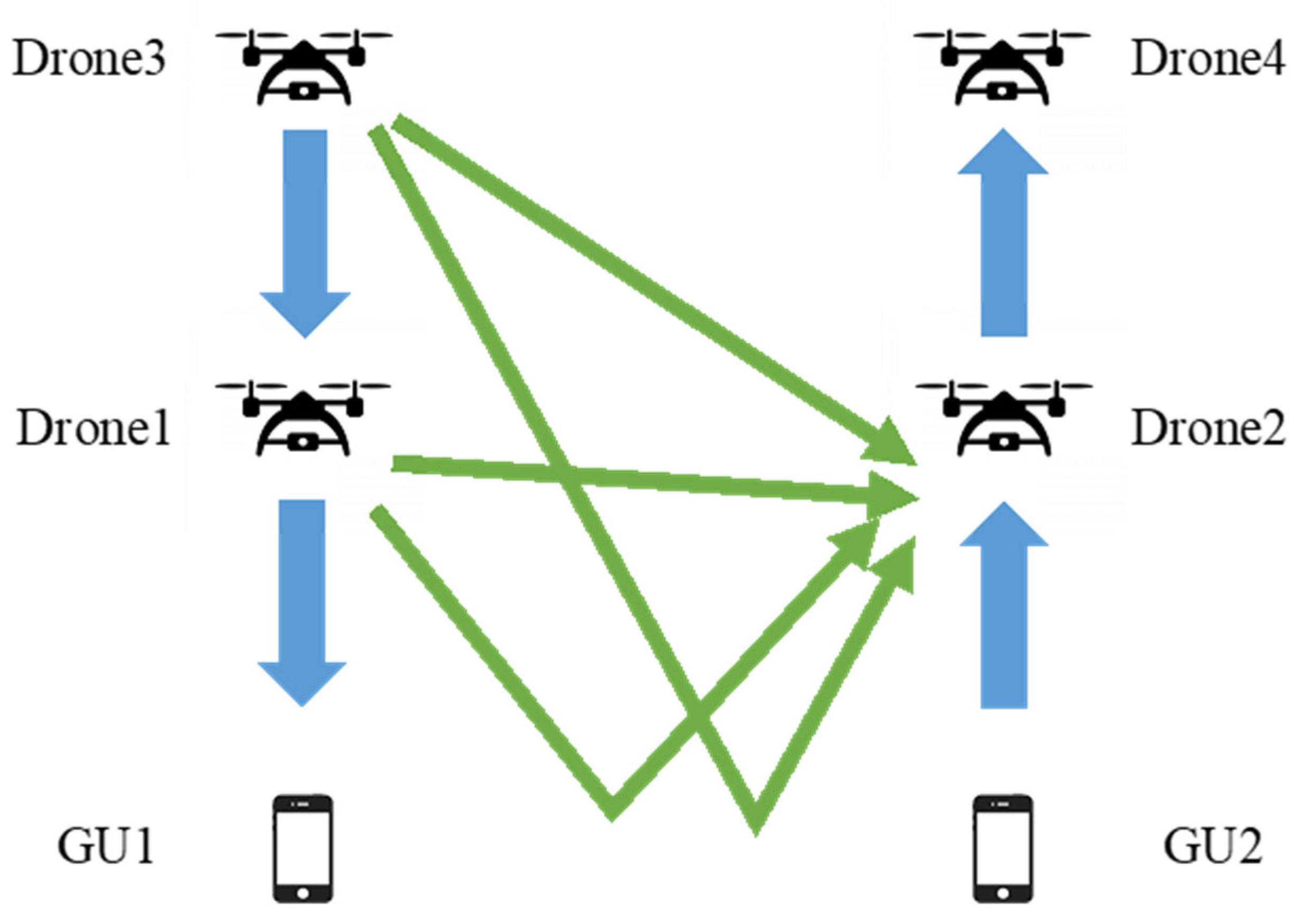
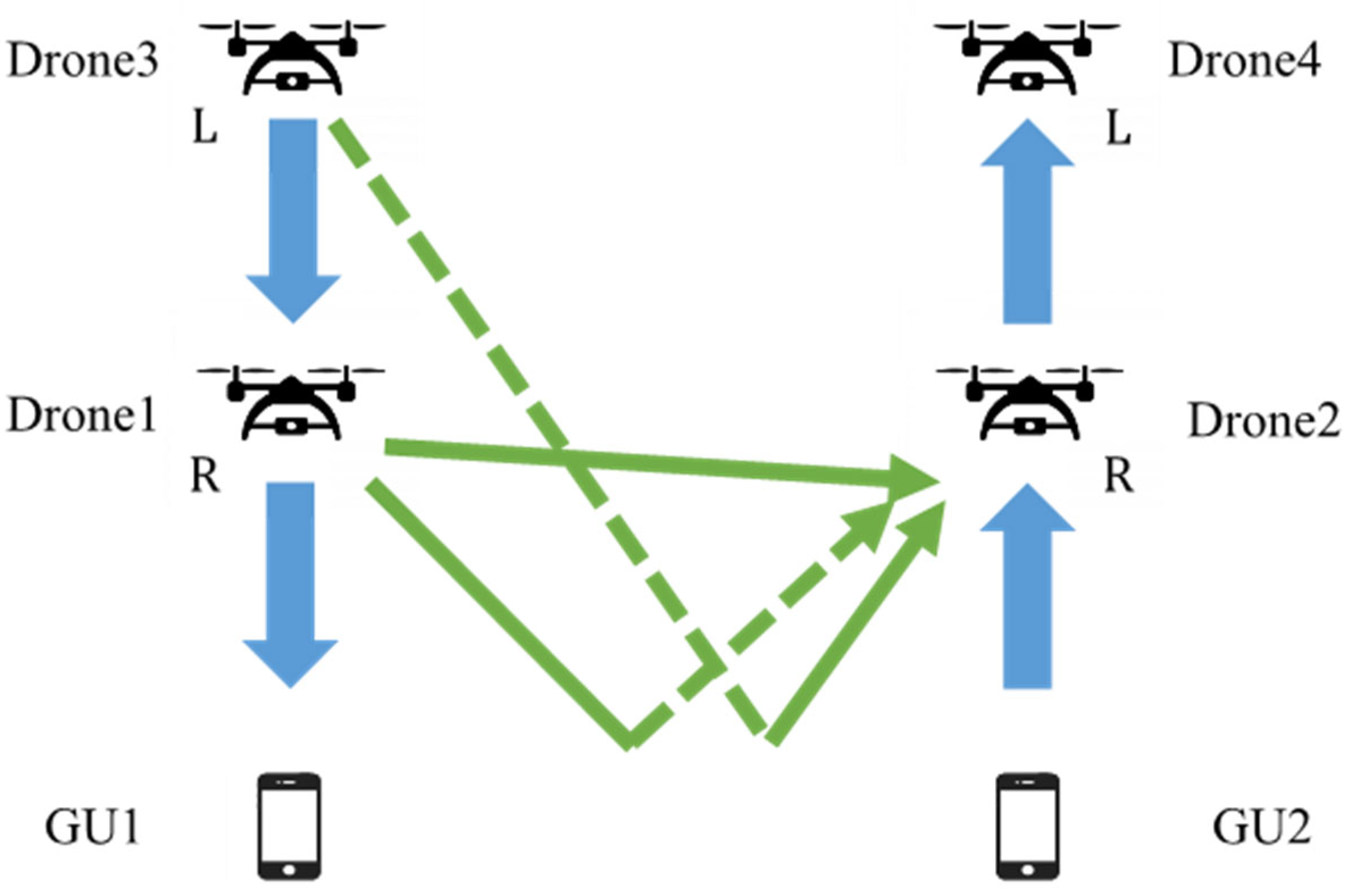
Figure 7 shows the signal reception model at Drone2 when linearly polarized antennas are used in both backhaul and access links as a conventional system. The blue signal represents the desired signal and the green signal represents the interference signal. In this case of linear polarization, the interference signals received by Drone2 are the direct and reflected waves from Drone1 and the direct and reflected waves from Drone3.
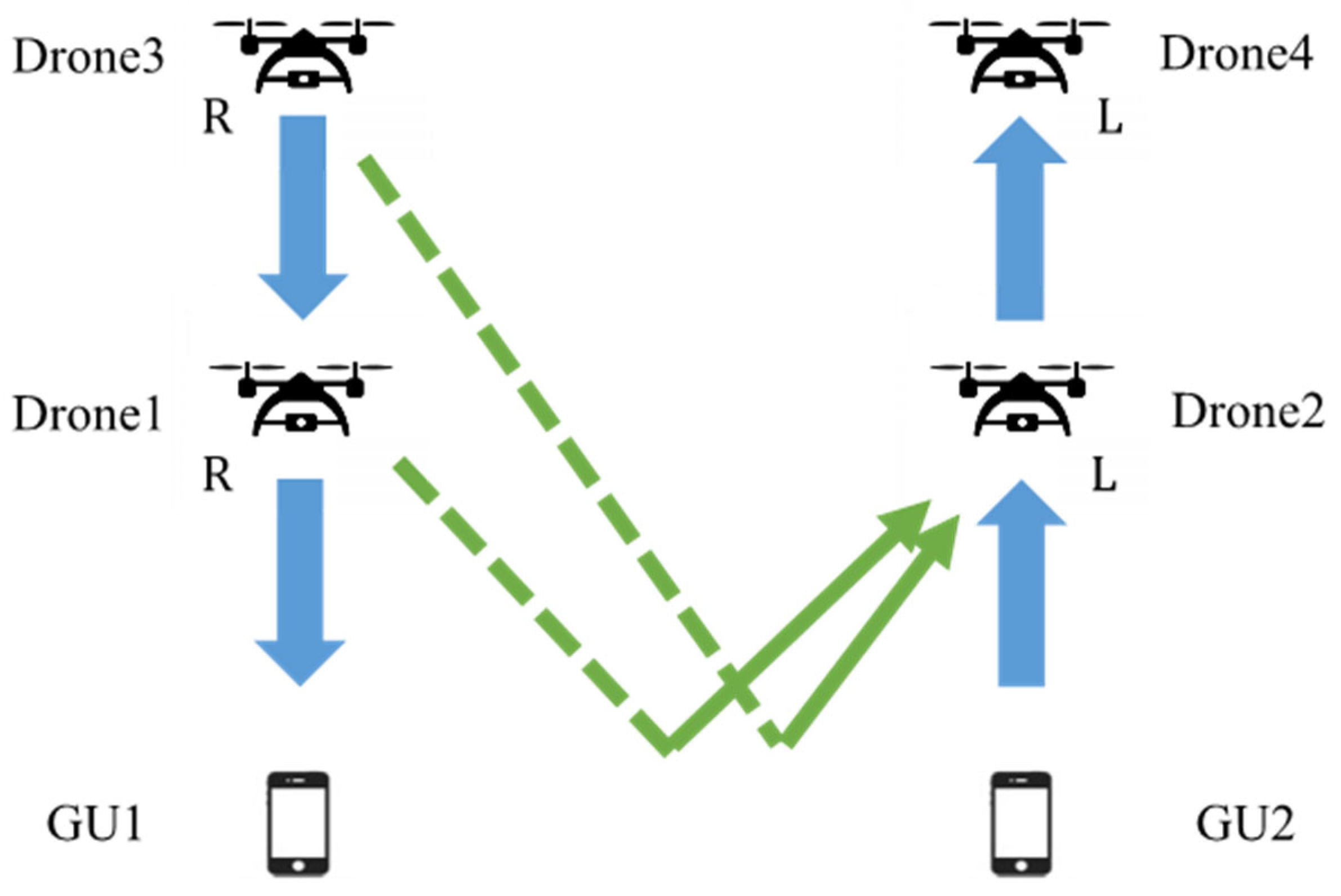
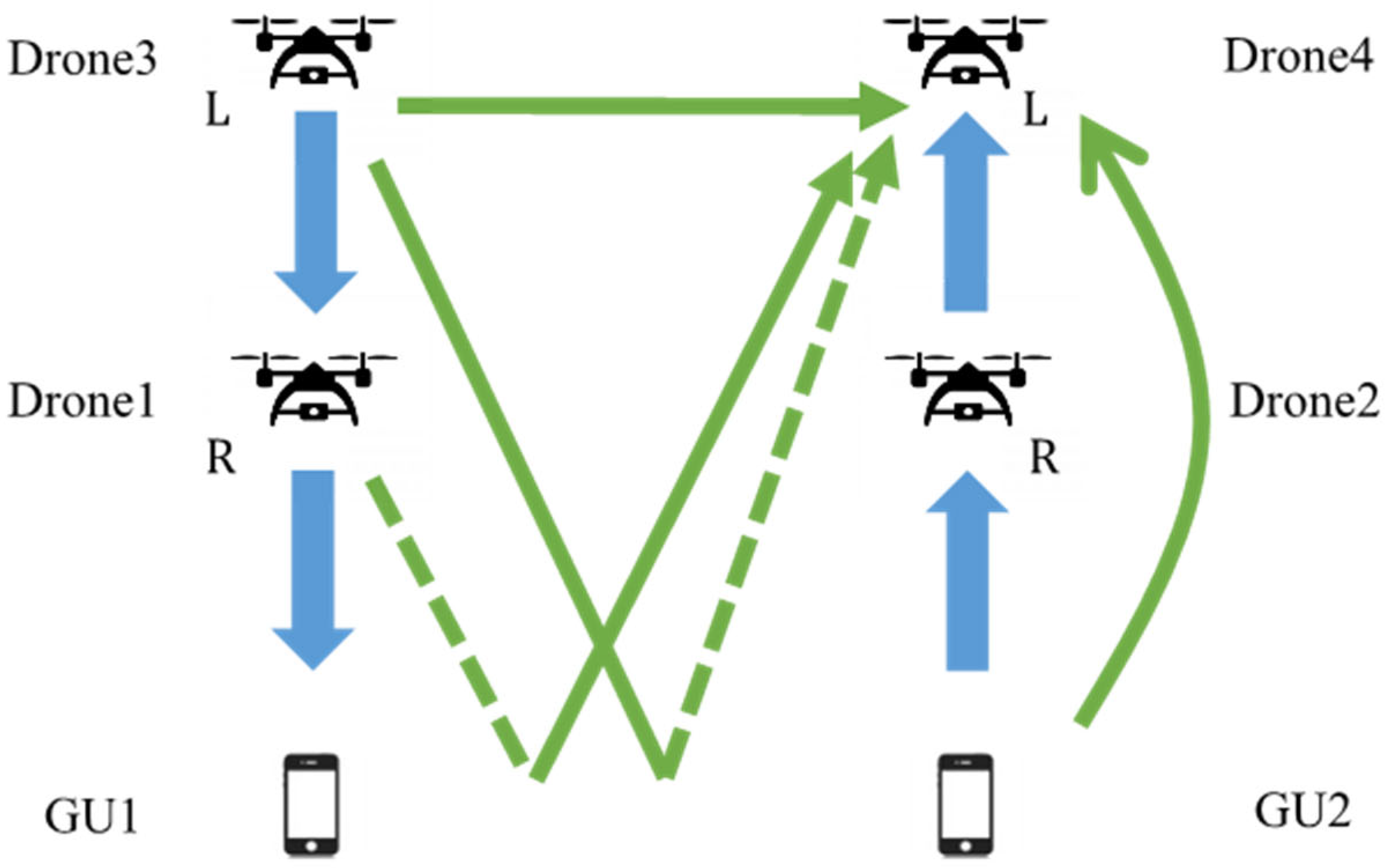
Figure 8 shows the signal reception model at Drone2 when the backhaul link and access link employ a same polarization plane e.g. right-handed circularly polarized antennas as depicted in the figure. The dashed line represents an inversed polarization plane with a different rotation direction i.e. left-handed circular polarization plane in this figure. As for the interference signal as a whole, the influence of the reflected wave is reduced owing to the polarization plane inversion at ground reflection. Thus, the influence of the direct wave becomes dominant in this proposed model.
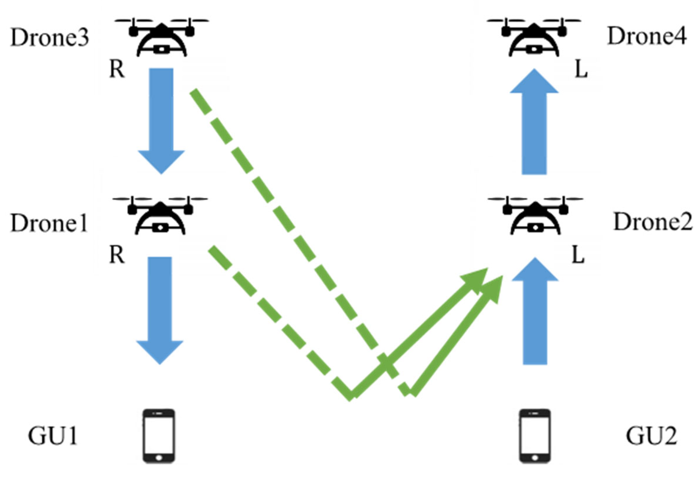
Figure 9 shows the signal reception model at Drone2 when the backhaul link and access link employ antennas of different polarization planes. Since the left-handed circularly polarized wave is transmitted from Drone3, it becomes a right-handed circularly polarized wave after reflection to be received at Drone2. Therefore, the reflected wave from the backhaul drone and the direct wave from the access drone dominate the entire interference signal in the model of
Figure 9.
Figure 10 shows the signal reception model at Drone2 when a same polarization plane is employed at each uplink or downlink communication links but different polarization planes are used at these two adjacent UL/DL systems. From the figure, the influence of reflected waves from neighboring backhaul drones and neighboring access drones dominates the interference signal as a whole.
Figure 7.
Signal reception model at Drone2 (linear polarization case).
Figure 7.
Signal reception model at Drone2 (linear polarization case).
Figure 8.
Signal reception model at Drone2 (same polarization antennas are used at both access and backhaul links, dashed line represents the inversion of polarization plane due to ground reflection).
Figure 8.
Signal reception model at Drone2 (same polarization antennas are used at both access and backhaul links, dashed line represents the inversion of polarization plane due to ground reflection).
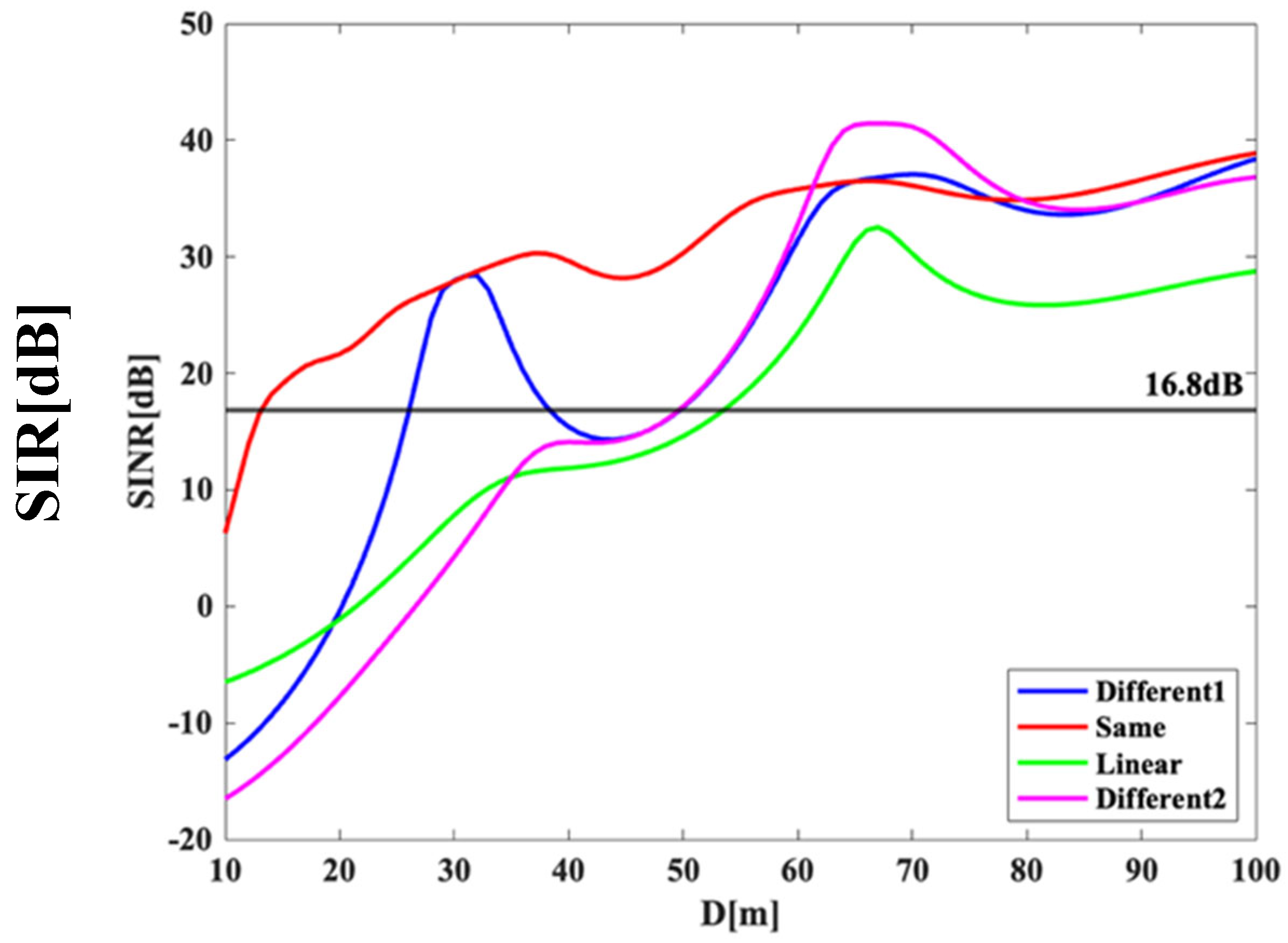
Figure 11 shows the SIR characteristics of Drone2 when
is varied from 10m to 100m, with both
and
fixed at 25m and
and
both fixed at 75m for the above four patterns of polarization combinations. The green curve shows the performance of the conventional linear polarization case in
Figure 7, just for the sake of comparison. The red line shows the case of
Figure 8 where the backhaul link and access link use same plane of polarization. Since the influence of direct wave is dominant, the SIR performance of this case almost outperforms other cases even when the distance between adjacent drones is shorten. It can be seen that
must be separated by approximately 13m or more to satisfy our system requirement of 16.8dB [
12]. Compared to the case without the existence of backhaul drones in
Figure 5, the new result reveals the necessity of increasing the separation distance between these adjacent UL/DL communication links to achieve a system’s target SIR under the existence of backhaul drones.
Figure 9.
Signal reception model at Drone2 (different polarization antennas are used at access and backhaul links).
Figure 9.
Signal reception model at Drone2 (different polarization antennas are used at access and backhaul links).
Figure 10.
Signal reception model at Drone2 (different polarization antennas are used at adjacent UL/DL communication links).
Figure 10.
Signal reception model at Drone2 (different polarization antennas are used at adjacent UL/DL communication links).
The blue line indicates the case where the backhaul link and access link employ antennas of different polarization planes as in
Figure 9 (denoted as “Different1” in the legend). It can be seen that
must be separated by about 26m or more to satisfy the system requirement for this type of polarization selection. The SIR performance of the blue curve temporarily takes a high value when
is about 30m and 68m. These can be explained by the nulls of the employed antennas.
The magenta line shows the performance when using different planes of polarization for uplink/downlink links separately as in
Figure 10 (denoted as “Different2” in the legend). It can be seen that
must be separated by about 55m or more to satisfy the system requirement. For this scenario, since the interference is dominated by the ground reflected waves from both Drone1 and Drone3, the separation requirement is even stricter compared to the two aforementioned cases. We can also remark that there is no significant difference in the SIR characteristics when
is sufficiently large, regardless of different circular polarization choices. In overall, as red curve shows the best performance, it is recommended to use antennas of a same type of circular polarization for all access/backhaul and UL/DL links. Such selection also simplifies the system design.
Figure 11.
SIR performance at Drone 2 under the existence of backhaul drones.
Figure 11.
SIR performance at Drone 2 under the existence of backhaul drones.
4.3. SIR Performance at the Backhaul Drones
SIR for Drone4, which is receiving signals, can be calculated in the same way as in
Section 4.1.
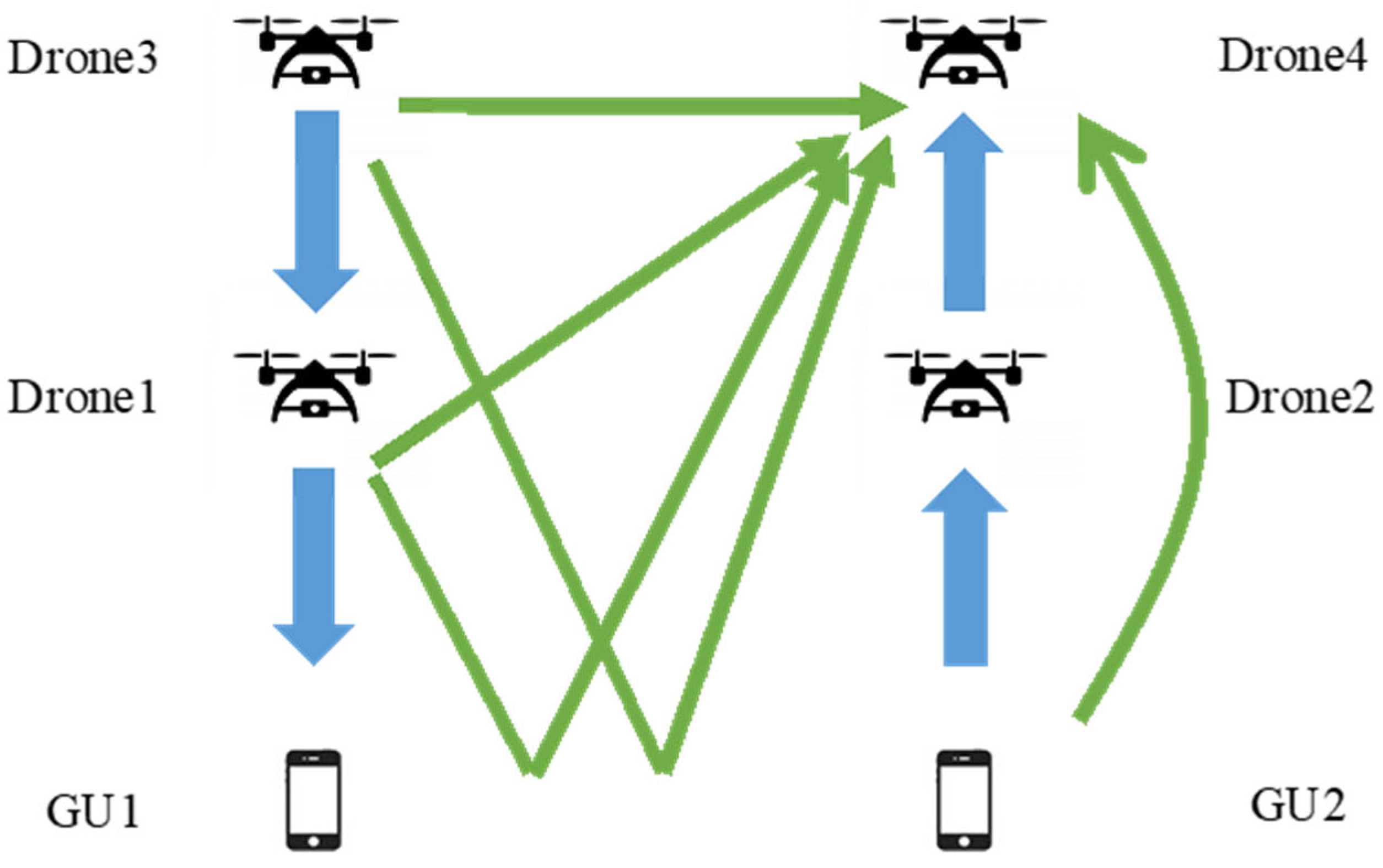
Figure 12 shows the signal reception model at Drone4 when using linearly polarized antennas at both the backhaul and access links as a comparison scheme. The blue signal represents the desired signal and the green signal represents the interference signal. In the case of linear polarization, the interference signals received by Drone4 are the direct and reflected waves from Drone1, the direct and reflected waves from Drone3, and the signal from GU2.
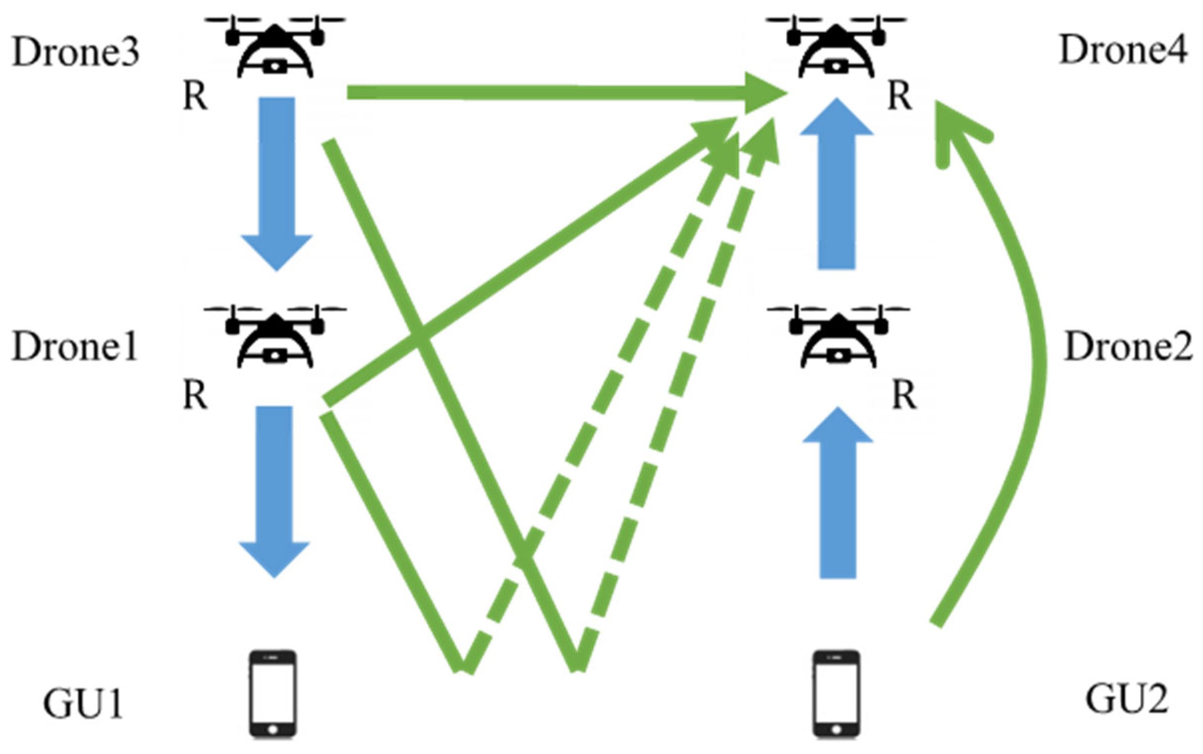
Figure 13 shows the signal reception model at Drone4 when the same circular polarization plane is used at both the access and backhaul links. Among all the interference signals, only the direct waves are dominant owing the polarization plane inversion of the ground reflected paths.
Figure 14 shows the signal reception model at Drone4 when different circular polarization planes are assigned to the backhaul and access link respectively. The interference signals received by Drone4 are the direct wave from Drone3, the reflected wave from Drone1, and the signal from GU2.
Figure 15 shows the signal reception model at Drone 4 when adjacent UL/DL drones communicate using different planes of polarization. In this model, the influence of reflected waves from adjacent access and backhaul drones is dominant due to the polarization plane inversion effect.
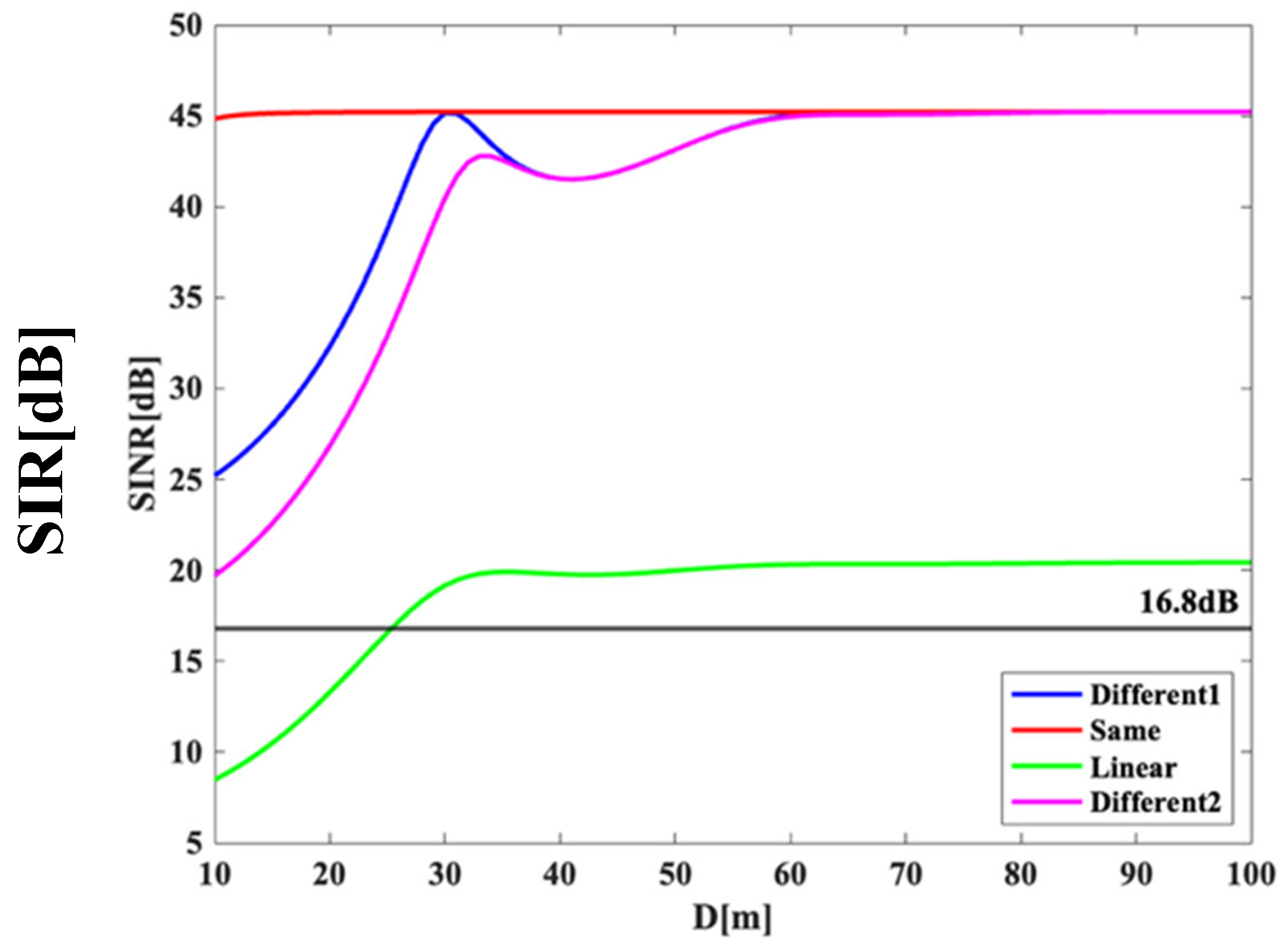
Figure 16 shows the SIR characteristics of Drone4 when
is moved from 10m to 100m, with both
and
fixed at 25m and
and
both fixed at 75m, as in
Section 4.2 for the aforementioned four patterns. The red line shows the case where the backhaul link and access link employ antennas of the same plane of polarization as shown in
Figure 13. Regardless of
, the SIR takes a nearly constant value of 45dB, much higher than the system requirement of 16.8dB. Such superior performance is owing to the fact that the polarization planes of the interference paths caused by ground reflection were inversed such that the only dominant interference source is from GU2, transmitting at lower transmit power.
The blue line shows the performance where different polarization planes are assigned to the backhaul and access drones respectively as shown in
Figure 14 (denoted as “Different1” in the legend). As the dominant interference source in this case is due to the ground reflection path from Drone1, the SIR performance gradually increases against larger separation
and achieves the peak when
is about 30m, that corresponds to the null of the receive antenna pattern at Drone4.
The magenta line shows the performance when different polarization planes are assigned for adjacent UL/DL drones as shown in
Figure 15 (denoted as “Different2” in the legend). Similar to the previous scenario, the dominant interference sources are from the ground reflection paths from both Drone1 and Drone3. It results into an almost same SIR performance trend as that of “Different1”, but at a lower value of SIR.
In the overall, the performance of applying circular polarization is superior to the conventional scheme of linear polarization shown by green curve of
Figure 16. For the proposed schemes, the SIR performance of all curves converges at the value of 45dB when enough
separation (larger than 60m) is attained. It means that in these regions, the effect of inter-drone interference is negligible and the only remaining interference source is from the ground user GU2. Among all of the comparisons scheme, similar to the analysis in Sect. 4.2, applying the same circular polarization plane to all the drones’ access and backhaul interfaces yields the best SIR performance.
Figure 12.
Signal reception model at Drone4 (linear polarization case).
Figure 12.
Signal reception model at Drone4 (linear polarization case).
Figure 13.
Signal reception model at Drone4 (same polarization antennas are used at both access and backhaul links).
Figure 13.
Signal reception model at Drone4 (same polarization antennas are used at both access and backhaul links).
Figure 14.
Signal reception model at Drone4 (different polarization antennas are used at access and backhaul links).
Figure 14.
Signal reception model at Drone4 (different polarization antennas are used at access and backhaul links).
Figure 15.
Signal reception model at Drone4 (different polarization antennas are used at adjacent UL/DL communication links).
Figure 15.
Signal reception model at Drone4 (different polarization antennas are used at adjacent UL/DL communication links).
Figure 16.
SIR performance at Drone 4 under the existence of backhaul drones.
Figure 16.
SIR performance at Drone 4 under the existence of backhaul drones.
5. Conclusions
In this research, as a wireless network system for disaster areas using drones, we proposed a system that transmits data in the 28 GHz band with a bandwidth of 100 MHz used in local 5G. Asynchronous operation has been considered in response to the demand for increasing uplink data capacity, such as sending videos from smartphones. We attempted to reduce the intra/inter-system interference by properly introducing antennas of circular polarization. In
Section 3, the two-wave model was applied to analyze the SIR performance between the access drone and the ground user. A comparison was made using different combination planes of polarization, and our numerical result revealed that the SIR characteristics were improved when antennas of the same kind of circular polarization were employed. In
Section 4, we furthermore evaluated the SIR of the system in the existence of backhaul drones. Similarly, it was found that deploying antennas of the same kind of circular polarization to all the access and backhaul links of both UL/DL yields the best performance. In overall, the introduction of circular polarization antennas in our system helped to reduce interference significantly compared to conventional approach of using linearly polarized antennas. Our future topics include constructing a Proof-of-Concept system and conducting outdoor experiments to demonstrate the effectiveness of introducing circularly polarized antennas in our drone communication networks.
Author Contributions
Conceptualization, T.O. and G.K.T.; methodology, T.O. and G.K.T.; soft- ware, T.O.; validation, T.O. and G.K.T.; formal analysis, T.O.; investigation, T.O. and G.K.T.; resources, T.O. and G.K.T.; data curation, T.O.; writing—original draft preparation, T.O. and G.K.T.; writing—review and editing, G.K.T.; visualization, T.O.; supervision, G.K.T.; project administration, G.K.T.; funding acquisition, G.K.T. All authors have read and agreed to the published version of the manuscript.
Funding
This research was funded by MIC SCOPE, grant number JP235003015.
Data Availability Statement
Not applicable.
Acknowledgments
We would like to thank the anonymous reviewers for their careful reading of our manuscript and their many insightful comments and suggestions to improve the quality of the manuscript. We would also like to acknowledge the Telecommunications Advancement Foundation for its financial support to complete part of this research.
Conflicts of Interest
The authors declare no conflict of interest.
References
- Hayat, S.; Yanmaz, E.; Muzaffar, R. Survey on unmanned aerial vehicle networks for civil applications: A communications viewpoint. IEEE Commun. Surveys Tuts. 2016, 18, 2624–2661. [Google Scholar] [CrossRef]
- Ghosh, A.; et al. Millimeter-wave enhanced local area systems: A high-data-rate approach for future wireless networks. IEEE J. Sel. Areas Commun. 2014, 32, 1152–1163. [Google Scholar] [CrossRef]
- Zhang, L.; et al. A survey on 5G millimeter wave communications for UAV-assisted wireless networks. IEEE Access 2019, 7, 117460–117504. [Google Scholar] [CrossRef]
- Ministry of Internal Affairs and Communications Japan. [WHITE PAPER] Information and Communications in Japan, 2011.
- Okada, T.; Tran, G.K. A Study on Antenna Polarization Plane for UL/DL Drone Access Network. In Proceedings of the 12th International Conference on Ubiquitous and Future Networks ICUFN 2021, Jeju Island, Korea, 17–20 August 2021; IEEE: Piscataway, NJ, USA, 2021; pp. 334–338. [Google Scholar]
- Mozaffari, M.; Saad, W.; Bennis, M.; Debbah, M. Drone Small Cells in the Clouds: Design, Deployment and Performance Analysis. In Proceedings of the IEEE Global Communications Conference, San Diego, CA, USA, Feb. 2016. [Google Scholar]
- Mozaffari, M.; Saad, W.; Bennis, M.; Debbah, M. Efficient Deployment of Multiple Unmanned Aerial Vehicles for Optimal Wireless Coverage. IEEE Commun.Lett. 2016, 20, 1647–1650. [Google Scholar] [CrossRef]
- Tran, G.K.; Ozasa, M.; Nakazato, J. NFV/SDN as an Enabler for Dynamic Placement Method of mmWave Embedded UAV Access Base Stations. Network 2022, 479–499. [Google Scholar] [CrossRef]
- Fukusako, T. Basics of Circularly Polarized Antenna, Corona, Inc., Japan, 2018.
- Parsons, J.D. The Mobile Radio Propagation Channel, 2nd ed.; John Wiley & Sons, Inc., US, 2000.
- Chia, S.; Gasparroni, M.; Brick, P. The next challenge for cellular networks: backhaul. IEEE Microwave Magazine 2009, 10, 54–66. [Google Scholar] [CrossRef]
- Okada, T. Research on Antenna Polarization in Drone Access Network with Uplink and Downlink. Master Thesis, Tokyo Institute of Technology, Japan, 2022. [Google Scholar]
|
Disclaimer/Publisher’s Note: The statements, opinions and data contained in all publications are solely those of the individual author(s) and contributor(s) and not of MDPI and/or the editor(s). MDPI and/or the editor(s) disclaim responsibility for any injury to people or property resulting from any ideas, methods, instructions or products referred to in the content. |
© 2023 by the authors. Licensee MDPI, Basel, Switzerland. This article is an open access article distributed under the terms and conditions of the Creative Commons Attribution (CC BY) license (http://creativecommons.org/licenses/by/4.0/).
