1. Introduction of Engineering Heterogenous Nucleation in Multiphase Alloys
Multiphase alloys which belong to eutectic systems, such as cast irons (Fe-C) and aluminum-silicon (Al-Si) alloys, are commonly used in metal casting industry due to good technological properties. For example, cast irons and Al-Si alloys with eutectic reactions have higher castability than the alloys solidified with single solid solution phase, like steels (with austenite) or wrought Al alloys (with α-Al). Mechanical performance of multiphase alloys strongly depends on the micro-structural dispersity and shape of microconstituents in the microstructure. Refining microstructure benefits most mechanical properties and one popular approach to refine microstructure is increasing population of grains via promoting heterogeneous nucleation. Therefore, controlling microstructure in multicomponent alloys by enhancing heterogeneous nucleation is critically important for obtaining high performance cast alloys. When compared to alloys with single solid solution phase, commonly used multiphase alloys, for example cast irons, are not deformable and the shape of the primary phases is not intended to be changed during heat treatment. This overview of the author’s publications addresses modifying the microstructure in the multiphase cast alloys during the solidification.
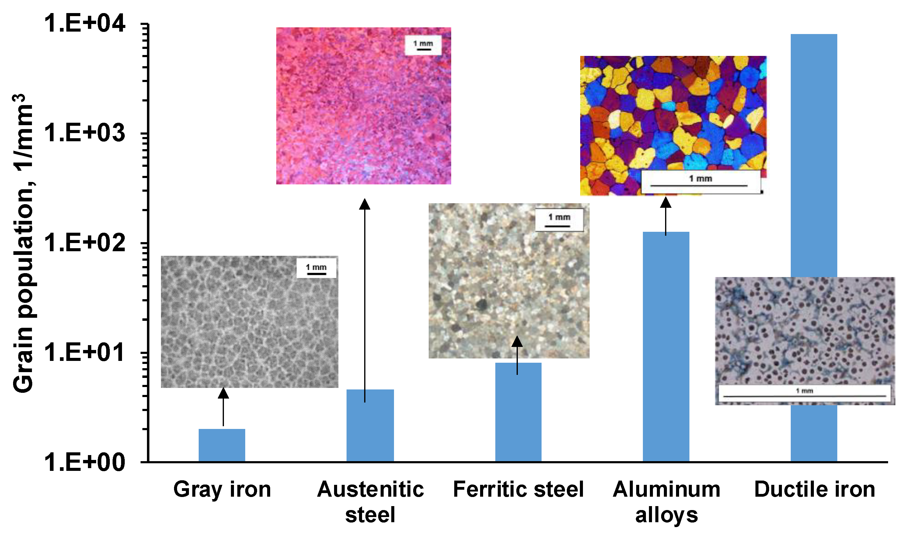
Considering size and number of structural units needed to nucleate in the different types of cast alloys (
Figure 1), inoculation of grains in the commercial multiphase alloys requires a significantly larger number of heterogeneous nuclei when compared to alloys solidified with single phase.
Homogeneous nucleation from stochastically formed nano-meter scale embryos requires a deep undercooling (~25 % of the solidification temperature, typically on the order of hundred degree Celsius) of the metallic melt to overcome the energy barrier. The observed undercooling of a few degrees Celsius in commercial metallic alloys indicates heterogeneous nucleation on the existing nuclei. If the melt is in contact with a flat, relatively large solid support, compared to the homogeneous nuclei at critical radius, this surface will facilitate heterogeneous nucleation by decreasing the total value of Gibbs energy with a function of
f(θ):
where:
ΔGhet is the Gibbs energy for heterogenous nucleation,
ΔGhom is the Gibbs energy for homogenous nucleation, and
θ is a contact angle at the triple junction between solid support, nuclei, and melt.
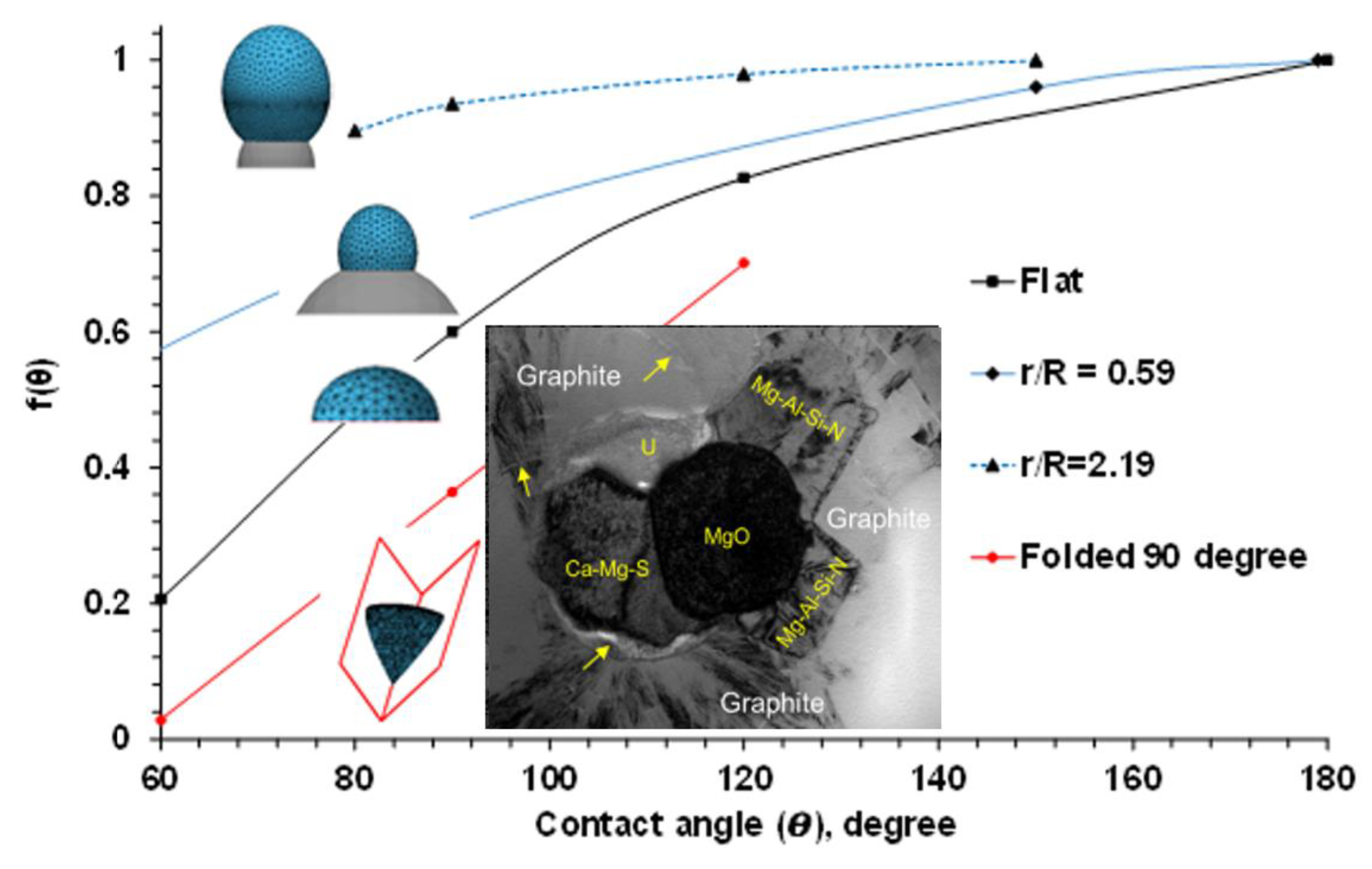
The real solid supports in the melt, which facilitate heterogeneous nucleation, are not infinite and ideally flat. To determine an optimal surface topology of heterogeneous nuclei, a SE-FIT software was used in our study [
1]. The function
f(θ) was simulated for a variety of sizes and shapes of potential heterogeneous nuclei, and the results are plotted in
Figure 2. It was found that decreasing the contact angle on an infinitely large flat substrate reduced
f(θ) and the needed undercooling for heterogeneous nucleation (critical undercooling). It should be noted that the effect of contact angle also depends on the support dimension and geometry. When nucleus with radius
R sits on a small spherical substrate with radius
r, decreasing the contact angle does not significantly impact
f(θ) or effectively reduce the critical undercooling. It was found that a higher than a minimal value of a dimensional
r/R ratio is needed to effectively facilitate the heterogeneous nucleation. The second factor is related to the geometry of the potential nucleation site, which is typically not flat or spherical. For example, formed in the ductile iron melt complex oxide, nitrides and sulfides have irregular shapes comprised convex and concave surfaces or folded internal corners (insertion in
Figure 2) [
2,
3,
4,
5]. The “folded” inclusions have a significant nucleation advantage relative to a flat support. Complex “folded” precipitates will generate additional sites for continuous nucleation. The different process routes to develop such complex heterogeneous nuclei in the liquid alloys by in-situ chemical reactions will be discussed in the later sections.
The thermodynamic analysis of heterogeneous nucleation provides theoretical basis for a variety of metallurgical inoculation processes that were designed using an engineering heterogeneous nucleation methodology.
2. Engineering Inoculation of Cast Iron with Spherical Graphite
2.1. Thermodynamic Simulation
Non-metallic inclusions play a vital role in graphite nodule nucleation for cast iron with spheroidal graphite (SGI). Because each graphite nodule needs a nucleation site, more than tens of thousands heterogeneous nuclei per mm
3 are needed to avoid undesirable cementite formation when liquid phase undercools below a meta-stable eutectic transformation temperature. Knowledge about the composition of heterogeneous nuclei is practically important and can be used to control solidification in SGI castings. A typical SGI metallurgical processing includes nodularization treatment by
Mg with rare earth (
RE) metals (
Ce, La) to promote formation of spherical graphite, followed by inoculation with
Fe75%
Si base inoculants containing active elements, such as
Al, Ca, Ba, Zr, Ce and
La. In the published results, thermodynamic simulations were performed to predict the types of non-metallic precipitates formed during the entire SGI processing, including melt nodularization and inoculation, as well as subsequent melt cooling and casting solidification [
2,
3,
4,
5,
6,
7,
8,
9].
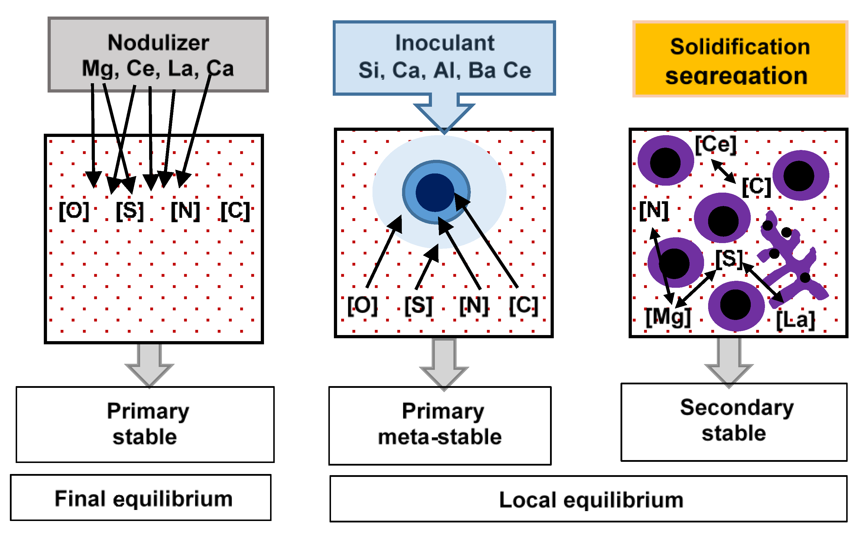
Thermodynamic simulations showed that, precipitates developed during SGI processing can be classified into three classes related to different formation conditions (
Figure 3):
primary thermodynamically stable precipitates developed in the melt during nodularization treatment with complex Mg-RE alloy;
primary meta-stable precipitates formed during Fe-Si-based inoculant dissolution;
secondary thermodynamically stable and meta-stable precipitates formed around the liquidus temperature in the mushy zone. Formation of the secondary precipitates during solidification relates to increasing affinity of N, S, and C to Mg and RE dissolved in the melt with lowering temperature and accelerated by positive segregation of these elements into the remaining melt. This category of precipitates mainly includes complex Mg-Al-Si nitrides.
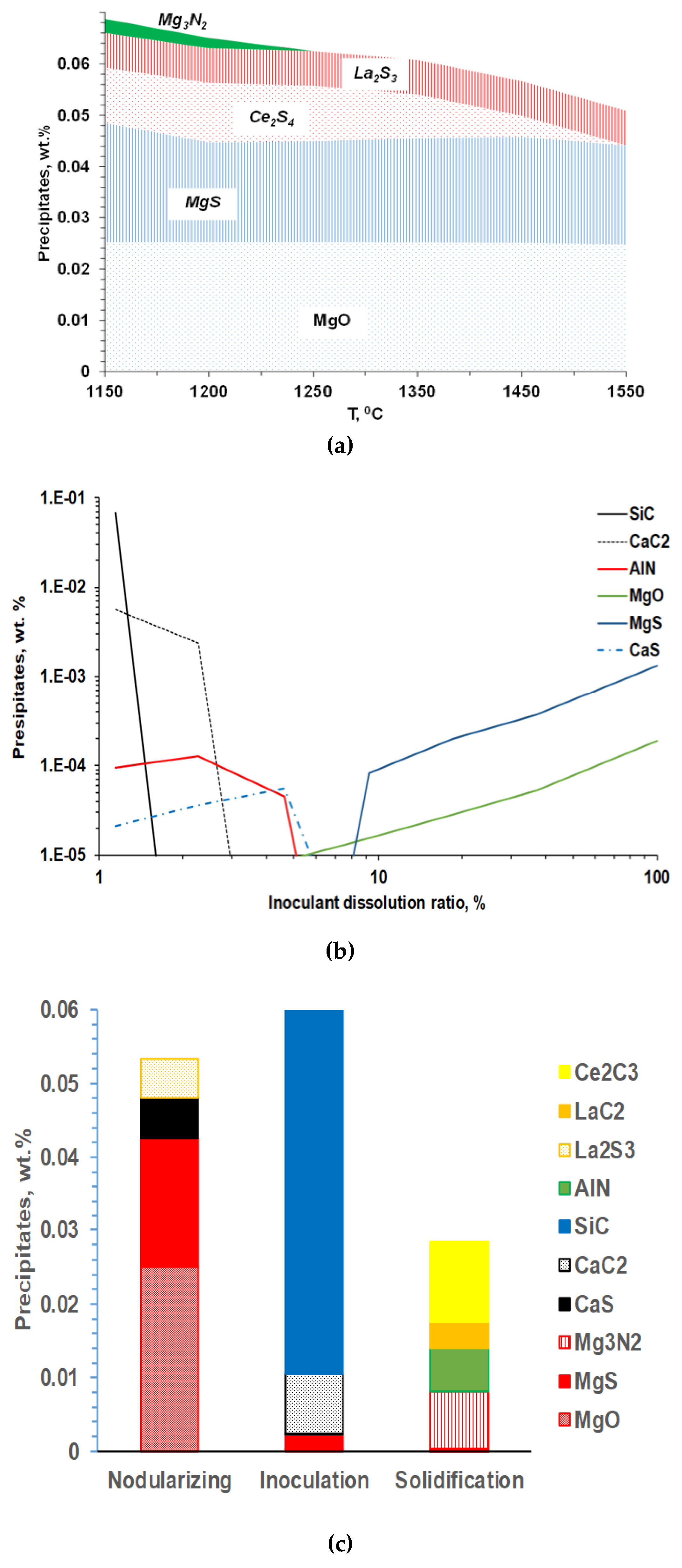
There are a lot of competitive reactions that could occur during the nodularization treatment, and thermodynamic simulations were used to simulate the composition of specific reaction products, considering the SGI melt chemistry, composition of additions and changing melt temperature during SGI processing (
Figure 4). The reaction products formed during
Mg-RE nodulizing treatment are typically thermodynamically stable in the melt (
Figure 4a). Meanwhile, equilibrium simulations of the reactions during
Fe-
Si-base inoculation showed that only a few new precipitates could be formed because this treatment followed deep melt refining of dissolved
S and
O during previous nodularization with
Mg. This indicated that equilibrium simulation cannot explain the strong effect of
Fe-Si inoculation on increasing graphite nodule count.
Instead, the local reactions in the melt during
Fe-
Si-based inoculant dissolutions were estimated by dynamic imitation of the dissolution zone in the melt to understand the interactions during the inoculation process [
7,
8]. Assuming quick irreversible reactions in inoculant dissolution zones, the formed reaction products were “removed” from the system after each simulation step. Accordingly, the several formed precipitates can be predicted during inoculant dissolution (
Figure 4b). For example, at the initial stage of inoculant dissolution (low dissolution ratio),
SiC and
CaC2 can be formed in the high silicon melt located close to the inoculant addition surface. It is important to note that these reaction products have a meta-stable nature and will be redissolved back into the melt during holding, which explained fading of inoculation during several minutes of holding of the melt.
Finally, precipitation of the new secondary inclusions in the mushy zone is possible because of the developing segregations of the active elements in front of the austenite. The family of these secondary inclusions includes
Mg-Al-Si or
Ti/Zr nitrides and the secondary precipitate composition depends on the dissolved residuals in the melt. It is important to mention that the co-precipitation of the secondary precipitates on the exiting solid surfaces resulted in multiple internal corners on the convex and concave surface. The increasing nucleation potential of such precipitate geometry was predicted from simulations (
Figure 2). The simulated precipitate families for entire SGI process simulation are shown in
Figure 4c.
2.2. Analysis of Heterogeneous Nuclei
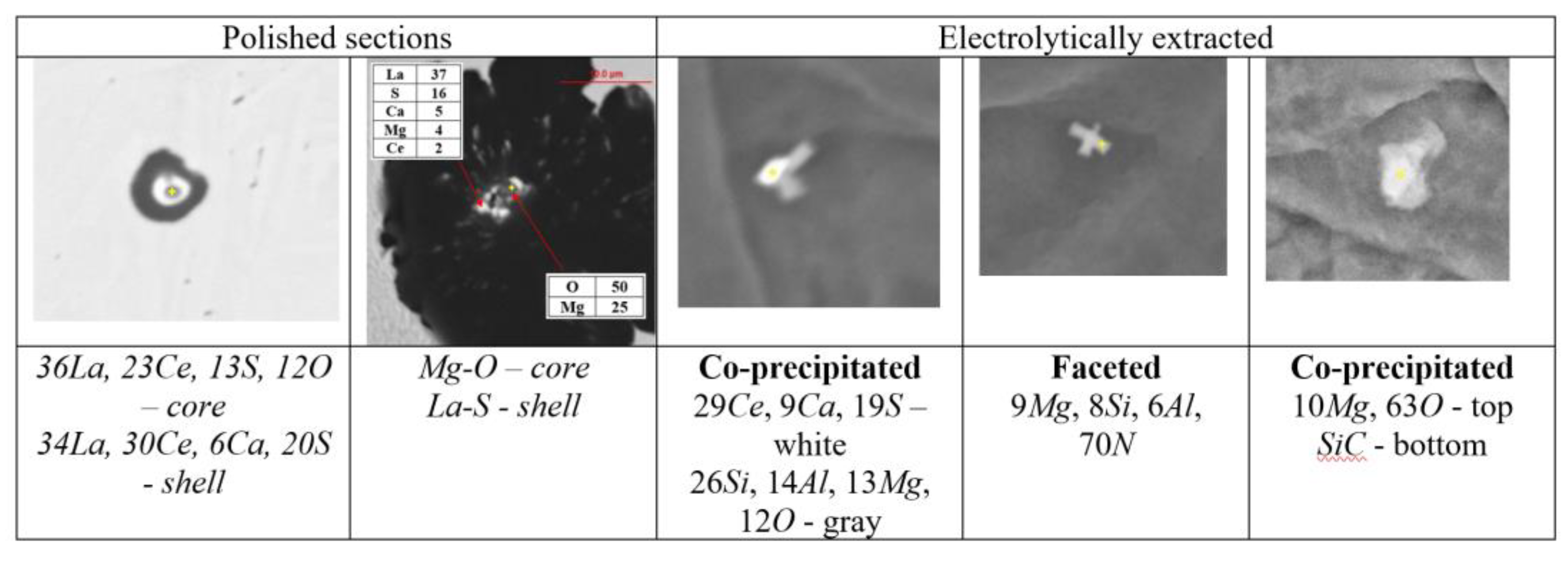
The thermodynamic simulations predict a variety of precipitates formed during SGI processing, mold filling, and casting solidification. To verify these predictions, the automated SEM/EDX analysis of inclusion family was performed [
3,
6]. A procedure for separately searching nuclei in the center of graphite nodules and located in the metal matrix was developed. To achieve reasonable statistical results, up to 10, 000 nodules were searched which gave information about several hundreds of nuclei. Examples of individual non-metallic inclusions detected inside graphite nodules on the polished cross section and electrolytically extracted from the matrix are provided in
Figure 5.
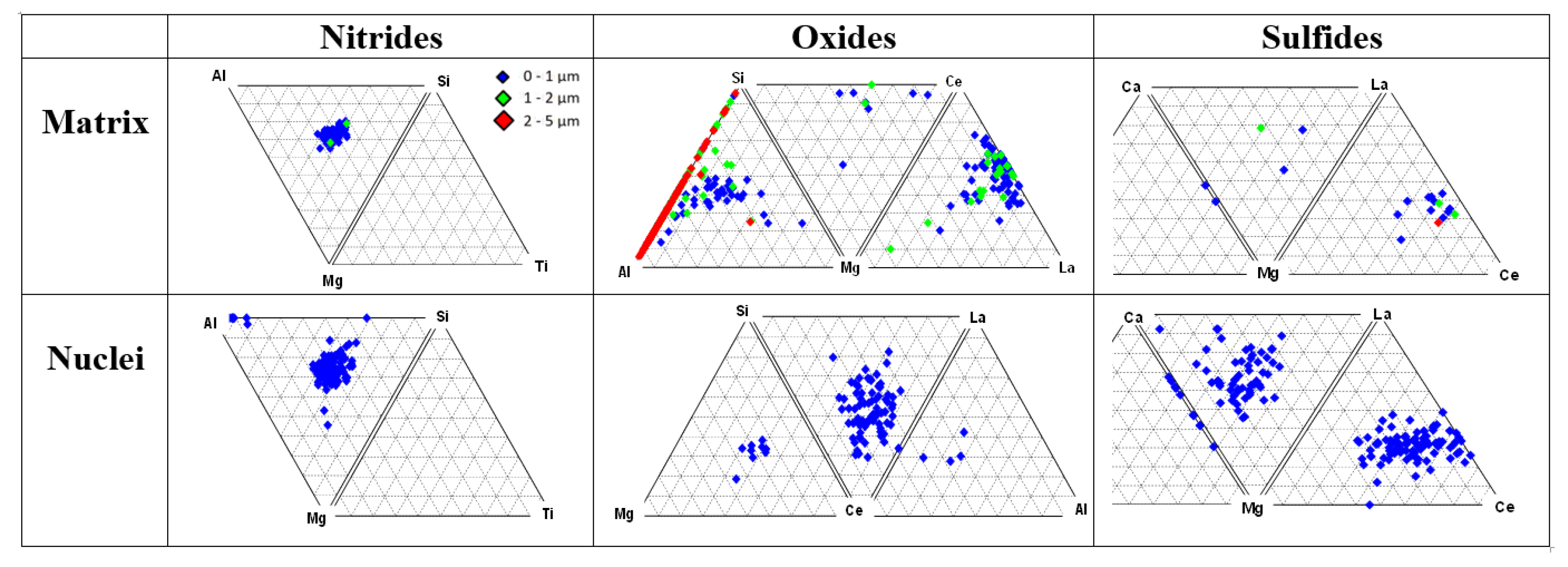
Ternary plots of classified oxides, sulfides and nitrides located in the matrix and at the center of graphite nodules are presented in
Figure 6. Three classes of precipitates were detected in the metal matrix and inside graphite nodules: complex
Mg-Al-Si nitrides, complex
Al-Si-Mg and
Mg-Ce-La oxides, and
Mg-Ca and
La-Ce sulfides. These types of reaction products in the melt were predicted by thermodynamic simulations (
Figure 4). The studied ductile iron contained a limited amount of other nitride forming elements (
Ti and
Zr); therefore, only the complex
Mg-Al-Si nitrides were detected in this case.
The results of automated SEM/EDX analysis of non-metallic inclusions in the industrial and laboratory melted SGI were described in [
3,
4,
5,
6,
7]. An example demonstrating a significant difference in composition of non-metallic inclusion located in the metal matrix versus inside graphite nodules can be observed in the ternary diagrams in
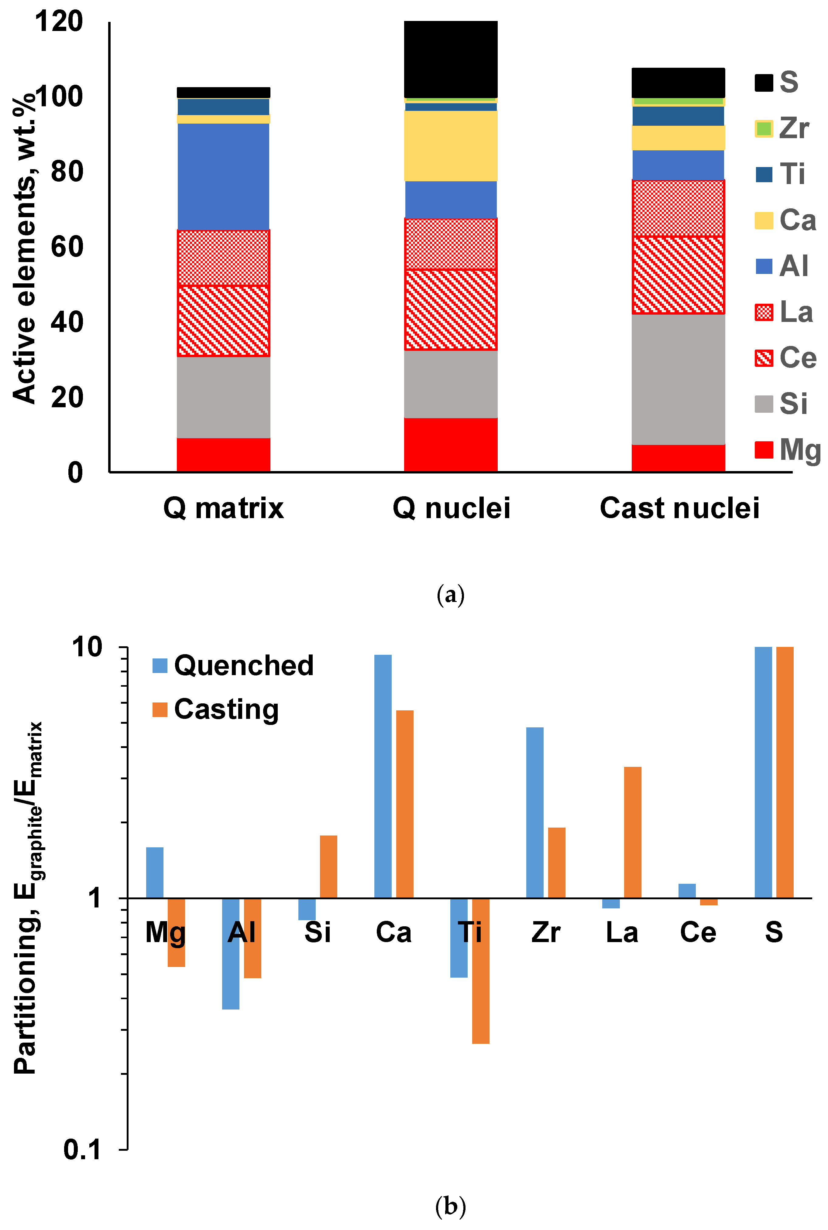
Figure 6. To quantify these differences, the average concentrations of active elements and their partitioning into those sited inside graphite nodules against the matrix were calculated for all detected inclusions (
Figure 7).
Ti has a large negative value of partitioning and is sited mainly in the matrix, while
Ca and
La sulfides have tendency to present in the graphite nuclei. Graphite nuclei contain significantly larger portions of
La and
Ca sulfides and
Zr nitrides which indicates their nucleation activity.
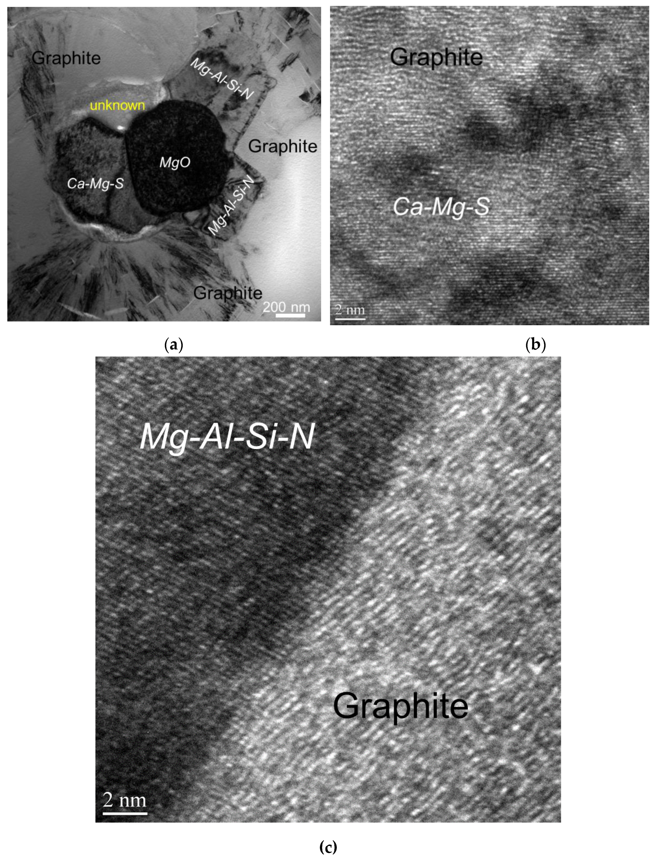
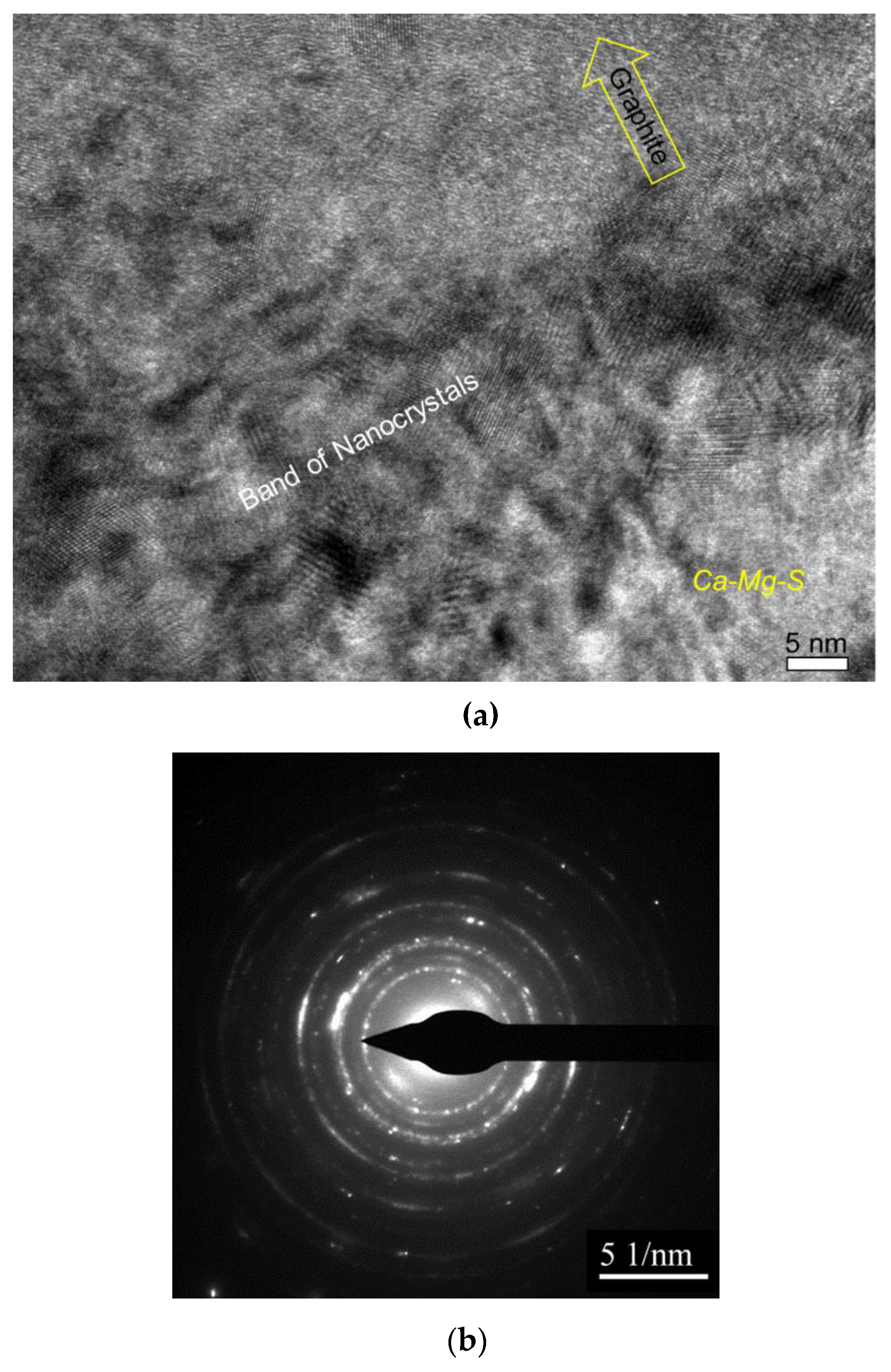
The authors [
7] conducted detailed atomic resolution TEM (Transmission Electron Microscopy) analysis of the interface between the complex heterogeneous nuclei and the graphite nodule and discovered the evidence of meta-stable reaction products which could be formed during inoculation process (
Figure 8).
The nanocrystal band which was located between complex precipitates and graphite nodule (
Figure 9) can be the product of transient reactions during the inoculation process with
Fe-Si addition (
Figure 4). An atomically rough interface of nanocrystalline band will be highly active in initialization of graphite nucleation because it contains plenty of sharp concave regions and provides greater surface areas.
2.3. Control Solidification Kinetics for Self-healing Microporosity in SGI
Thermodynamic simulations and an experimental searching methodology of graphite nodule nuclei were used for optimization of SGI processing, and the term engineering of non-metallic inclusions in SGI for controlling graphite nodule nucleation is suggested by the author to describe this methodology [
2]. The SGI melt treatment optimization was motivated by the development of desired:
types of non-metallic inclusions to initiate heterogeneous nucleation of graphite nodules;
topology of these precipitates (dimension, number, and shape) to become active nuclei;
sequence of precipitate formation for prolongation of nucleation events until the end of solidification.
Practical applications of engineering of non-metallic inclusions in SGI for controlling graphite nodule nucleation were described by the author with colleagues and students in the articles related to reducing shrinkage micro-porosity in casting [
2,
9,
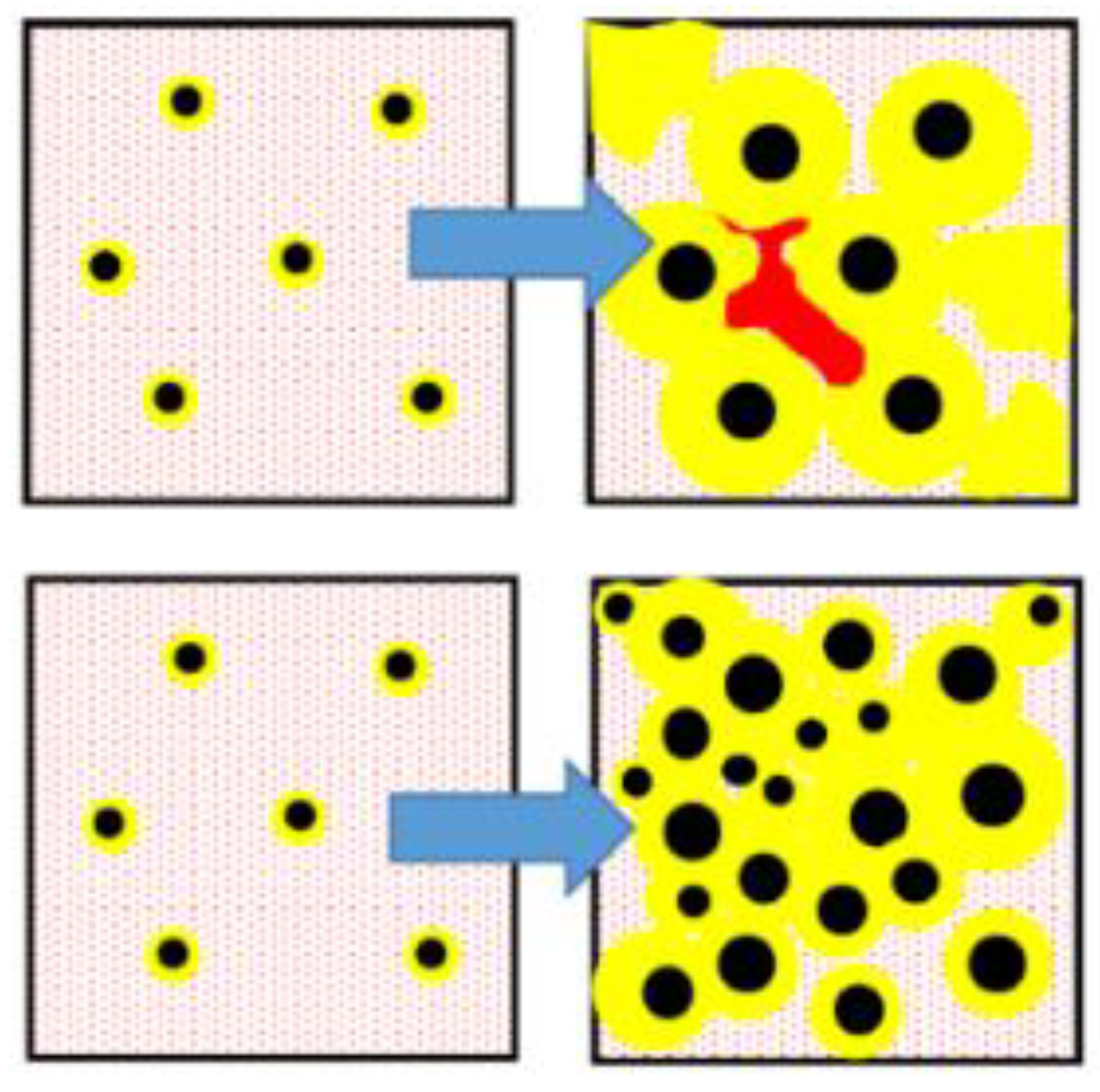
14]. Graphite precipitation from the melt causes a volume expansion during the solidification, therefore control of the kinetics of graphite nodule precipitation could be used as an effective way to eliminate shrinkage micro-porosity. Let us consider two solidification scenarios: (i) instantaneous graphite nodule nucleation at maximal undercooling and (ii) continuous graphite nodule nucleation toward the end of solidification. In the first solidification scenario, the volume increase, caused by massive graphite growth during the early solidification stage, will provide pressure on mold/casting interface and the soft casting surface could swell when the casting is contained in the not rigid mold. The following reduction of melt volume upon cooling will be not compensated because developed solid network blockades direct feeding of isolated melt pockets and micro-porosity will be formed (
Figure 10, top). The second scenario assumes the transient continuous nucleation and growth of graphite nodules to the end of solidification. This scenario will decrease micro-porosity (
Figure 10, bottom). In the ideal case, the latter solidification mode could provide self-healing shrinkage in the castings solidified without risers. The technical possibility of self-healing shrinkage by the combination of intrinsic factors (effective melt inoculation) with extrinsic factors (increasing mold rigidity) was experimentally confirmed in SGI.
To verify this assumption, two experimental SGI with different intensity of heterogeneous nucleation were intentionally produced by variation in inoculation parameters [
10]: SGI #1 was inoculated by foundry grade
Fe75%
Si and poured at high temperature (1400°C) and SGI #2 was treated by
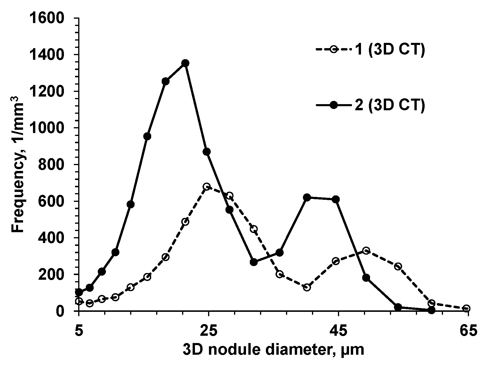
Ce-bearing (slower fading rate) inoculant and poured at low temperature (1320°C). To induce micro-porosity formation, the riser-less test designs consisted of a horizontal plate with top vertical cylinders, where microporosity was expected and was evaluated using density measurement and microcomputed tomography (µ-CT) scanning. 3D-morphological characteristics of graphite nodules were determined by µ-CT scanning and the obtained statistical data is discussed with respect to graphite nodule nucleation mode and casting soundness. It was shown that the 3D nodule diameter distributions are not monotonic in both inoculated SGI. A set of large nodules coexisted with sets of medium and small particles. However, well inoculated SGI#2 treated by
Ce-bearing inoculant had significantly higher graphite nodule volume number and a larger portion of small nodules when compared to SGI#1 treated by foundry grade ferrosilicon inoculant (
Figure 11).
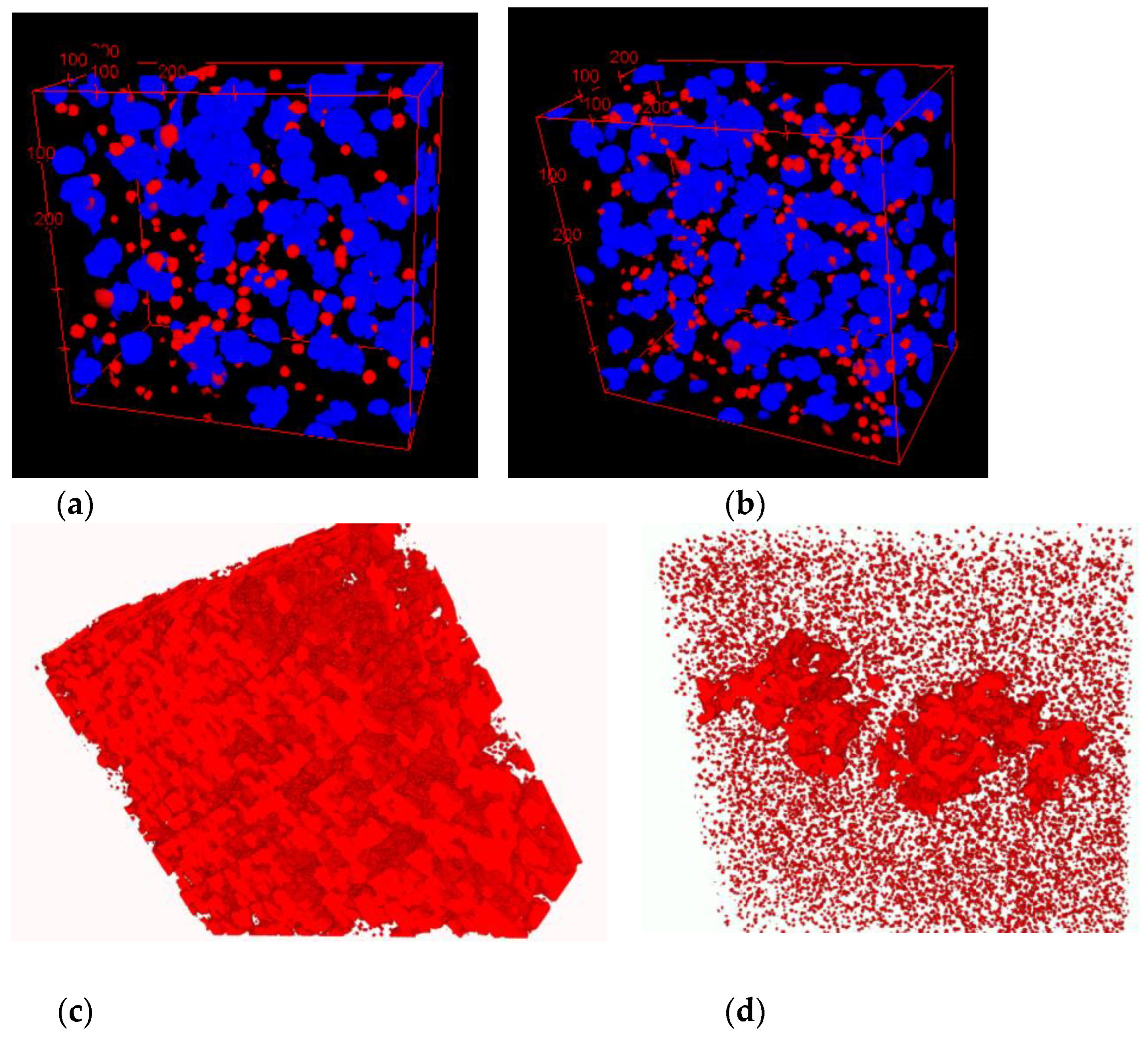
A visual presentation of graphite nodule distributions in three even groups by diameter is given in
Figure 12a,b for both SGI. Color code was applied: blue for large and red for small nodules, while medium nodules were removed to better visualize clustering of small nodules in interdendritic regions where cast iron solidified at the end. 3D analysis showed significantly less level of microporosity in SGI#2 (red highlights in
Figure 12b,c). Effective inoculation by
Ce-bearing inoculant at lower temperature of SGI #2 provided a higher volume nodule number and well-defined bi-modal nodule diameter distribution with larger portions of small and medium diameter nodules. The space distribution pattern of graphite nodules and bi-modal diameter distribution indicate that effective inoculation promotes continuous nucleation towards the end of solidification in addition to the early wave of graphite nucleation. Therefore, the control of graphite nodule nucleation mode by effective melt inoculation can be used to promote multi-wave nucleation throughout solidification and to decrease the propensity for micro-shrinkage.
These results showed a practical application of engineering heterogeneous nucleation for control solidification kinetics and structure in SGI; therefore, a novel method for the structural reconstruction of solidification kinetics in cast iron with spherical graphite (SGI) was suggested by the author [
13]. The ideal spherical shape of graphite nodules and the assumptions, that the nodule nucleation rate
n=dN/dτ=f(τ) and the growth velocity
V =dR/dτ =ψ(τ) are time (
τ) dependent functions, were used in numerical integrator to simulate an arbitrary graphite nodule diameter distribution. This simulated distribution was fitted to the real experimental 3D graphite nodule distribution using inverse simulation program by minimizing error function. The obtained nucleation
f(τ) and growth
ψ(τ) functions present the solidification kinetics which will develop a similar to observed experimental 3D nodule diameter distribution. The experimental structure parameters were obtained from µ-CT analysis [
10] or by converting experimental 2D distribution from polished section to the virtual 3D using the method suggested by the authors [
15].
The structural reconstruction of solidification kinetics from experimentally observed 3D distribution of graphite nodules was used to determine how graphite nodules were developed in the real castings and visualize the effects of cooling rate and inoculation [
13]. It was shown that SGI solidification kinetics in the industrial castings significantly differ from those predicted by basic instantaneous nucleation models. The cooling rate and inoculation have large impacts on the kinetics of graphite nodule nuclei formation during solidification.
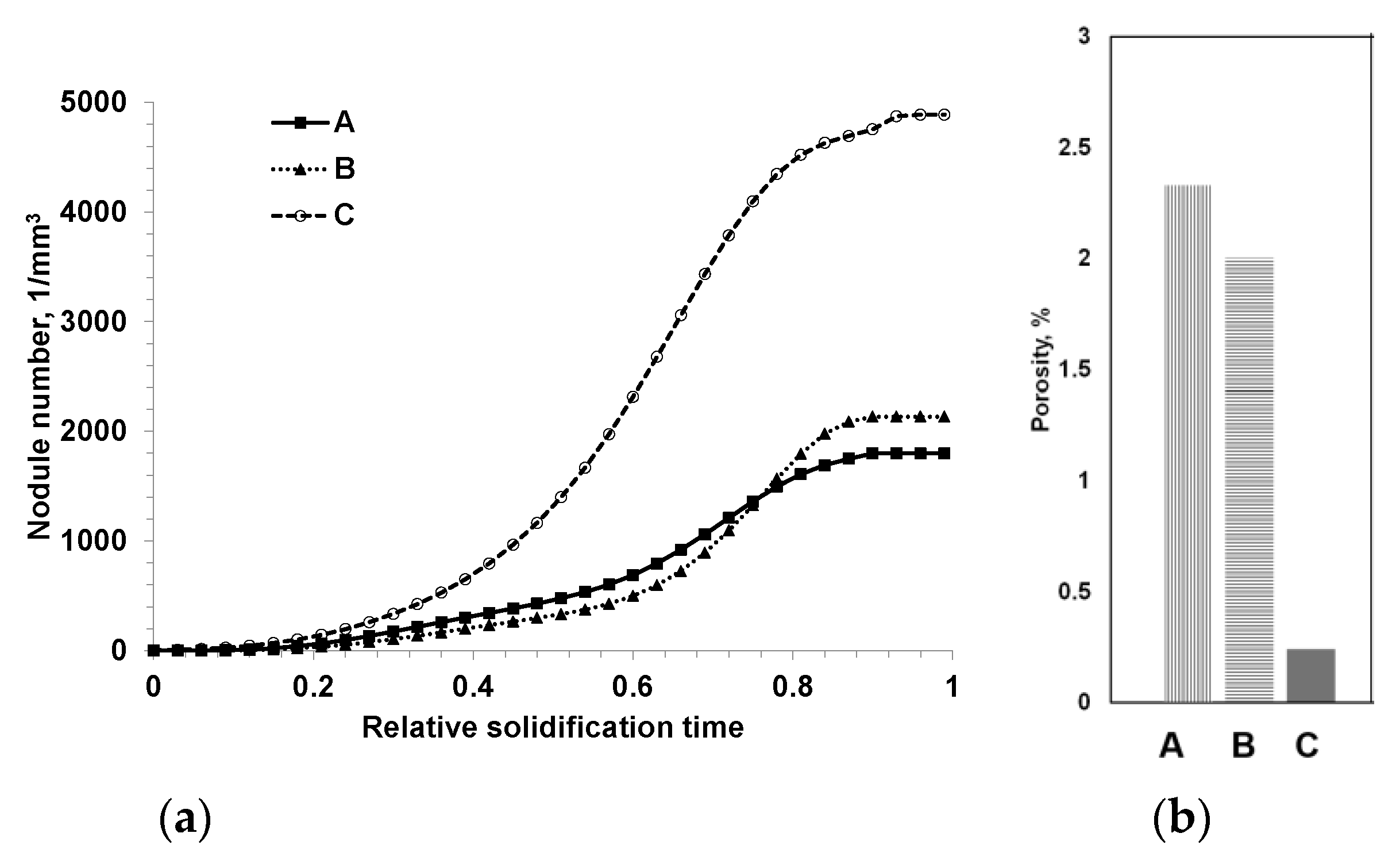
Figure 13 presents kinetics of nodule number development during solidification in three SDI castings produced with different inoculation parameters and measured micro-porosity [
14]. It was proved that the observed bi-modal distribution of nodule size in well inoculated SGI is related to the second nucleation wave. The suggested method provides insight into the nucleation process in SGI casting and can be used as a tool for process control, for example, self-healing micro-porosity.
3. Effect of Heterogeneous Nucleation on Shape of Primary Faceted Phases in Alloys
In previously discussed cases, engineering heterogeneous nucleation was used to control microstructure in cast iron with spherical graphite. In this part of overview, the authors would like to demonstrate that efficient nucleation can be used also to control the shape of primary precipitates, formed directly from the melt in multi-component hyper-eutectic alloys. In the resent years, such alloys are considered multifunctional to provide unique properties, for example wear and creep resistances. The main challenge for production of hyper-eutectic compositions is related to the tendency to form large, faceted dendrite/star type primary phases because they are free growing in the melt without restrictions.
The nucleated in the melt small crystals have near equilibrium compact shape which can be predicted by Gibbs-Curie-Wullf’s theorem that relates the crystal shape to anisotropy of surface energy. However, the following instabilities of freely growing interfaces produce morphological shape evolution. The factors that lead to shape instability include: (i) surface energy of a curved interface, (ii) atom attachment kinetics, (iii) trapping solute elements, (iv) mass transport of alloying elements, and finally, (v) possible constrained growth in the liquid channels at the end of solidification. Because of these disturbances, the solidified crystal begins to develop a complex dendritic shape, growing in a kinetically but not thermodynamically preferred crystallographic direction. Consequently, at low anisotropy of the solid-liquid interfacial energy in metallic phases, the developed non-faceted dendrites exhibit large radius of tip, while covalent and ionic phases with high anisotropy of the solid-liquid interfacial energy will exhibit sharp faceted morphology.
Two practical methods can be used to improve the shape of primary phases in casting from hyper-eutectic alloys: increasing cooling rate and effective nucleation. The two methods work differently but resulted similarly by minimizing the dimensions of melt envelop around individual crystal which limits turbulence in crystal growth. Engineering tools could be used to control the shape of primary phases and the several examples are described below [
16,
17].
3.1. Modification of shape of primary Nb carbo-nitrides in 20%Cr, 15%Ni, 2%Nb austenitic steel.
Niobium alloying is used to prevent creep in
Cr/Ni alloying austenitic steel; however, primary
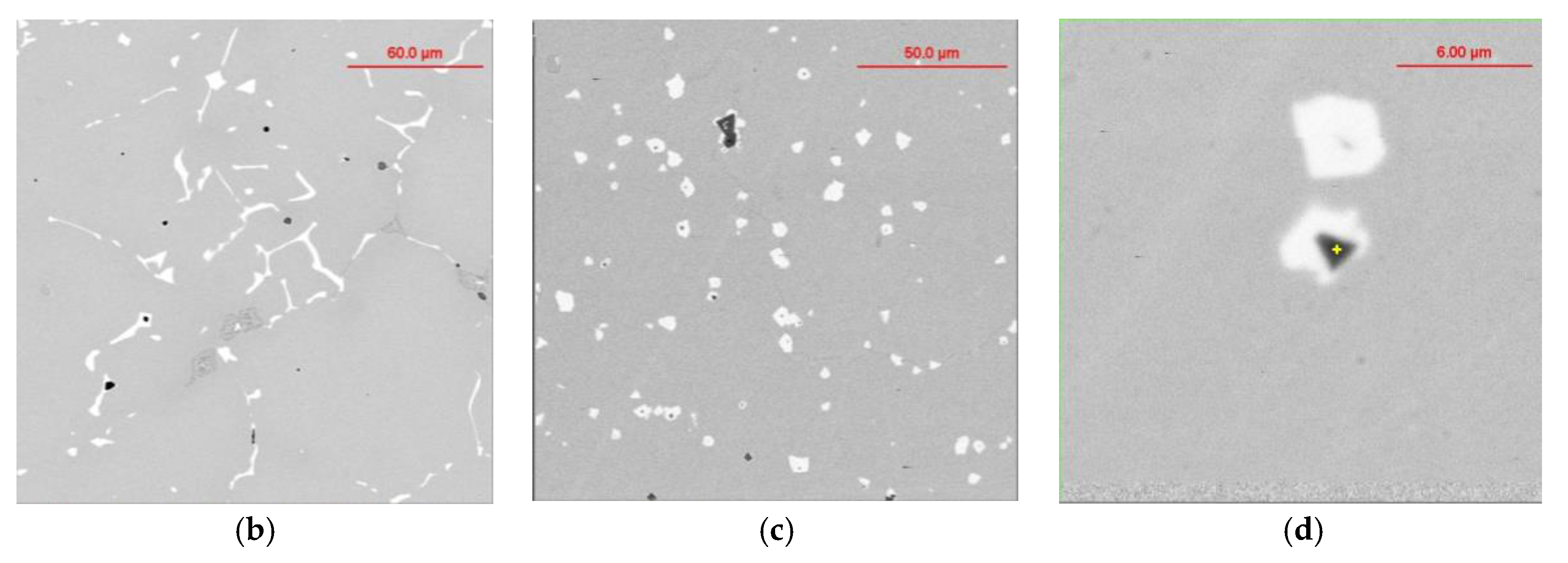
Nb carbonitrides forms a network of faceted, plate like precipitates located at grain boundary, which negatively impact the steel’s ductility (
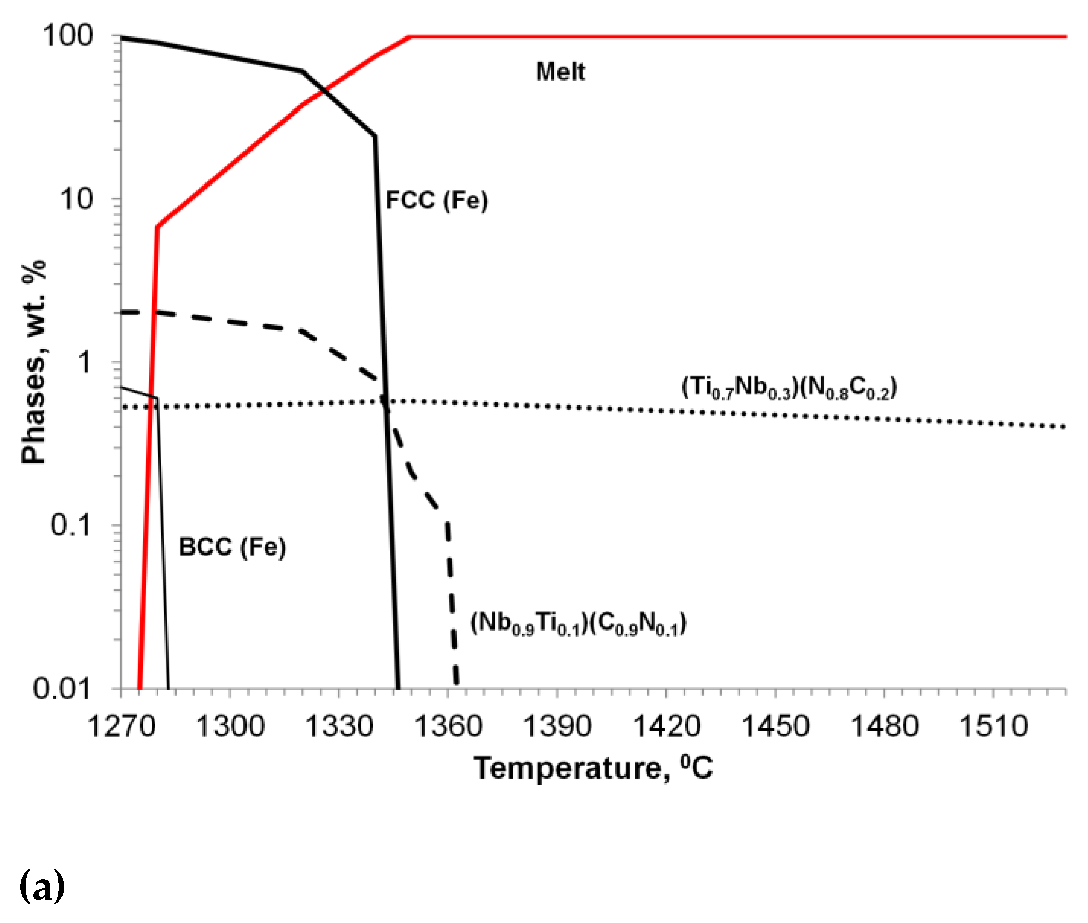
Figure 14b). Simulated sequence of primary
Nb carbonitride formation above austenite liquidus temperature is shown in
Figure 14a. Thermodynamic simulation showed the possibility of heterogeneous nucleation of primary
Nb-based carbonitrides by on the early precipitated
Ti-based nitrides. Co-precipitation of
Nb-base carbonitride changes plate-like topology on compact faceted isolated crystals (
Figure 14c). EDX analysis (
Figure 14d) revealed the composition of
Ti-based nitrides inside co-precipitated
Nb-base carbonitride. A TEM sample was prepared using the focused ion beam to examine the interface between these phases. The boundary between the two phases appeared relatively flat at high magnification using TEM (
Figure 15a), EDX line scan was used for phase identification (
Figure 15b), and selective area electron diffraction indicated that
Nb-based and
Ti-based compounds are mostly epitaxial.
3.2. Modification of shape of primary covalent phases in hyper-eutectic non-ferrous alloys.
Shape modification of primary covalent phases (
Si, Mg2Si and
AlSb) in several hypereutectic alloys on
Al- and
Mg-based was investigated [
16,
17]. These types of alloys recently discussed for different friction, wear, and creep resistant applications. They contain primary phases with covalent atomic bond: for example,
Si crystals in
Al-18%
Si alloy,
AlSb crystals in
Al-5.5%
Sb alloy, or
Mg2Si in hypereutectic
Al-Mg-Si and
Mg-Si alloys. All these phases had irregular star- and plate- like faceted shapes in casting (Figures 16a and 17a).
Design of additions for shape modification of primary covalent faceted crystals was done from analysis of its capability to in-situ in the melt form the heterogeneous nuclei at optimal temperature window above the liquidus temperature. Typically, inoculants were taken from the next Group of elements in Periodic System, for example,
P for
Al-Si, Al-Mg-Si and
Mg-Si alloys and
Se or
Te for
Al-Sb alloy. Thermodynamic simulation predicted in-situ formation of heterogeneous nuclei such as
AlP in
Al-Si alloy. In
Al-18%
Si alloy, the addition of 0.05%
P increases the number of primary
Si-crystals and decreases their average size by 3-4 times (
Figure 16b) and the shape of the primary
Si crystals was converted to compact rectangular with faceted planes. Thermal analysis indicated increasing liquidus temperature and decreasing undercooling of primary
Si phase after promoted heterogeneous nucleation with fine
AlP precipitates.
Modification provided similar shape modification in the other mentioned hyper-eutectic alloys.
Figure 17 illustrates shape changes in hypereutectic
Al-Sb alloy treated by 0.5%
Te. The cores of primary
AlSb intermetallic phase in modified alloy contained the complex heterogeneous nuclei that were in-situ formed attributed to the reaction of
Te additions with alloy components.
4. Conclusions
The overview aims to summarize the published studies by the authors in co-authorship with colleagues and students on different aspects of engineering heterogeneous nucleation in solidified cast alloys with multiphase structure formed during solidification. The engineering heterogeneous nucleation has a unique possibility to modify the cast structure in the desired direction to improve casting quality. The described thermodynamic simulations and experimental tools were used to design process parameters and provided methodology is applicable for engineering heterogeneous nucleation in different alloys. The several steps for engineering heterogeneous nucleation included design of active additions, optimization of topology of heterogenous nuclei, thermodynamic simulation of process parameters, and set of experimental methods such as an automated SEM/EDX analysis of precipitate family. Such methodology was used as a practical tool for self-healing micro-porosity in SGI by enhancing heterogeneous nucleation. The overview briefly provided practical details of mentioned processes and full description could be found in the referred articles. The author appreciates the great efforts that the co-authors have made on the original articles which were overviewed here.
Author Contributions
Simon Lekakh - conceptualization, data gathering, writing—original draft preparation; Jingjing Qing - visualization and review. All authors have read and agreed to the published version of the manuscript.
Acknowledgments
The author gradually thanks all coauthors of overviewed articles. The mentioned studies were done at Metal Casting Laboratories at Missouri University of Science and Technology and Georgia Southern University and supported by American Foundry Society and Ductile Iron Society. The authors very appreciate their long-term support.
Conflicts of Interest
The authors declare no conflict of interest.
References
- Arvola, D.; Lekakh, S.; O'Malley, R.; Bartlett, L. Two Inoculation Methods for Refining As-Cast Grain Structure in Austenitic 316L Steel, Int. J. Metalcast 2019, 13, 504–518. [Google Scholar] [CrossRef]
- Lekakh, S. ; Engineering Nucleation Kinetics of Graphite Nodules in Inoculated Cast Iron for Reducing Porosity, Met. Mater. Trans B 2018, 50B, 890–902. [Google Scholar]
- Lekakh, S. ; Searching for Graphite Nodule Nuclei Using Automated SEM/EDX Analysis, Int. J. Metalcast 2020, 14, 1078–1089. [Google Scholar] [CrossRef]
- Lekakh, S.; Richards, V.; Peaslee, K. Thermo-chemistry of Non-metallic Inclusions in DI, Int. J. of Metalcast 2009, 4, 25–37. [Google Scholar] [CrossRef]
- Lekakh, S.; Robertson, D.; Loper, C. Thermochemistry and Kinetics of Iron Melt Treatment, Trans. World Foundry Congress Proceedings, UK, 2006.
- Lekakh, S. Effect of Non-metallic Inclusions on Solidification of Inoculated Spheroidal Graphite Iron, Int. J. Metalcast 2019, 1, 47–57. [Google Scholar] [CrossRef]
- Qing J.; Lekakh, S.; Xu, M.; Field, D. Formation of Complex Nuclei in Graphite Nodules of Cast Iron, Carbon 2021, 171, 276-288.
- S Lekakh, S.; Loper C. Improving inoculation of ductile iron, AFS Trans. 2013, 111, 885-894.
- Lekakh, S. Effect of Non-metallic Inclusions on Solidification of Inoculated Spheroidal Graphite Iron. AFS Trans. 2018, 126, 129–138. [Google Scholar]
- Lekakh, S.; et al. 3D Characterization of Structure and Micro-porosity in Two Cast Irons with Spheroidal Graphite. Materials Characterization 2019, 158, 109991. [Google Scholar] [CrossRef]
- Lekakh, S.; et al. , Micro-CT Quantitative Evaluation of Graphite Nodules in SGI, Int. J. Metalcast. 2020, 14, 318–327 (2020). [Google Scholar] [CrossRef]
- Lekakh. S.; Khayat, M.; Effects of Metallurgical Factors on Micro-porosity in Ductile Iron, AFS Proceedings of the 123rd Metalcasting Congress, Atlanta, USA, Paper 19-157, 2019.
- Lekakh, S. Structural Reconstruction of Solidification Kinetics in Cast Iron with Spherical Graphite. ISIJ Int. 2016, 56, 812–818. [Google Scholar] [CrossRef]
- Lekakh, S.; Hrebec, B. ; Solidification Kinetics of Graphite Nodules in Cast Iron and Shrinkage Porosity, Int. J.Metalcast 2016, 10, 4, 389–400. [Google Scholar]
- Lekakh, S., Qing, J., Richards, V., Peaslee, K.; Graphite Nodule Size Distribution in Ductile Iron, Transactions of the American Foundry Society, 2013.
- Khudokormov, D.; Galushko, A.; Lekakh, S.: Modification of Shape of Fe-containing Phases in Aluminum alloys, Foundry Production, USSR, 1975 5, 18.
- Khudokormov, D.; Galushko, A.; Lekakh, S.; Formation of Magnesium Silicide and Fe-containing Phases in Aluminum and Magnesium Alloys, Foundry Production, USSR, 1973, 3, 25.
|
Disclaimer/Publisher’s Note: The statements, opinions and data contained in all publications are solely those of the individual author(s) and contributor(s) and not of MDPI and/or the editor(s). MDPI and/or the editor(s) disclaim responsibility for any injury to people or property resulting from any ideas, methods, instructions or products referred to in the content. |
© 2023 by the authors. Licensee MDPI, Basel, Switzerland. This article is an open access article distributed under the terms and conditions of the Creative Commons Attribution (CC BY) license (http://creativecommons.org/licenses/by/4.0/).
