2. Materials and Methods
The open channel design, consist in a duct in which the liquid flows with a surface subjected to atmospheric pressure and the flow is assumed fully developed at the channel inlet.
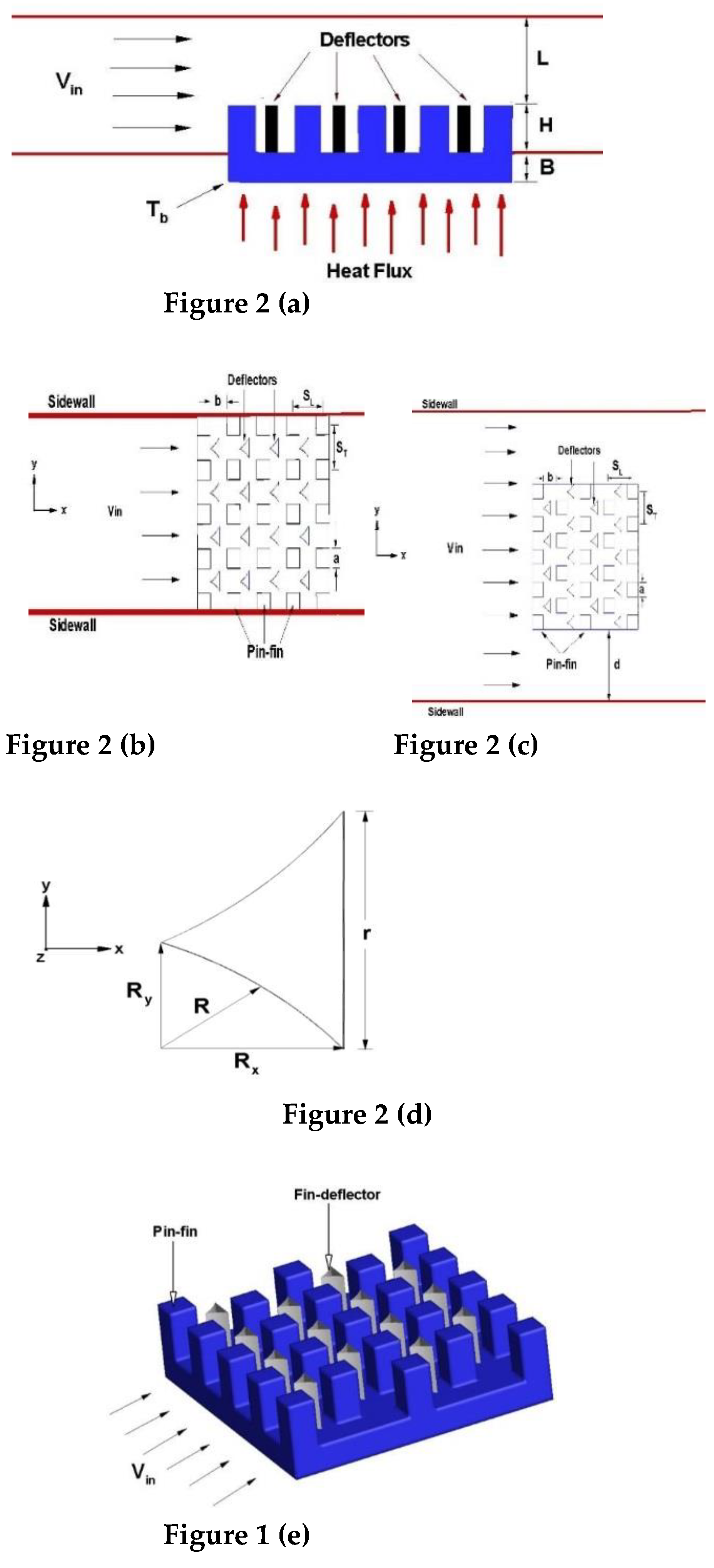
Figure 2a shows the inlet velocity,
Vin, height of the fins, H, heat flow to the bottom is applied, distance between the tip of the fins and the roof of the channel, L, height of base of heat sink model, B, the temperature of the base of heat sink, T
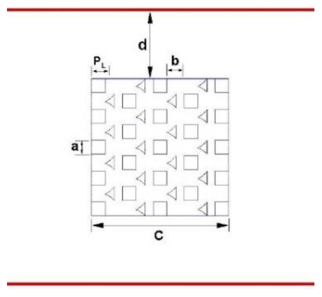
b. Deflectors element are placed between rectangular fin profile for all configurations of this study. Top view in
Figure 2 (b) is showed, also the arrangement and position of the deflector elements, in addition to fin spacing,
b,
ST and
SL are transversal and longitudinal pitch respectively, finally
a represent the fin side length. The channel walls are immovable.
Figure 2c shows the top view of the open channel design in a staggered arrangement for rectangular fin profile and the deflectors implemented. The shapes of the deflectors implemented in the heat sink model are presented schematically in
Figure 2d,e is a 3D view of the heat sink model,
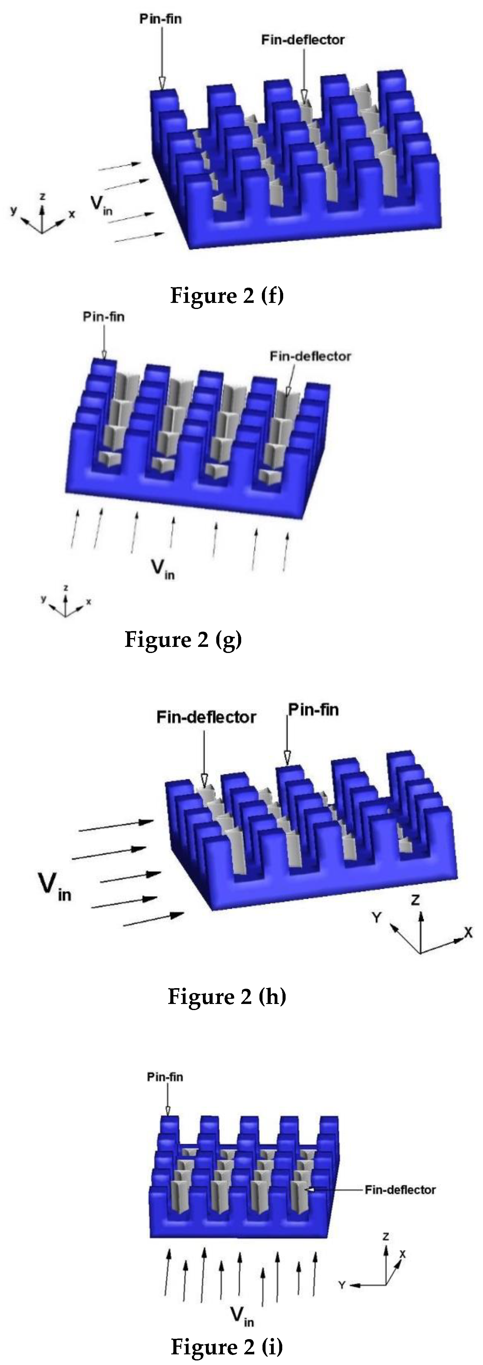
Figure 2f,g show a view 3D model lateral and frontal respectively of the heat sink with increased size deflector in the flow direction and finally, the
Figure 2h,i show a view 3D model lateral and frontal respectively of the heat sink with decreased size deflector in the flow direction. Each parameter was based on the thermal most performance and total assessment of the system to remove heat.
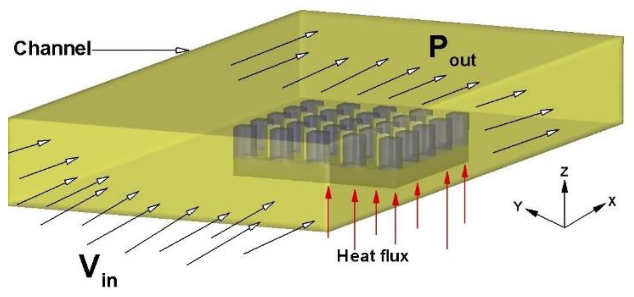
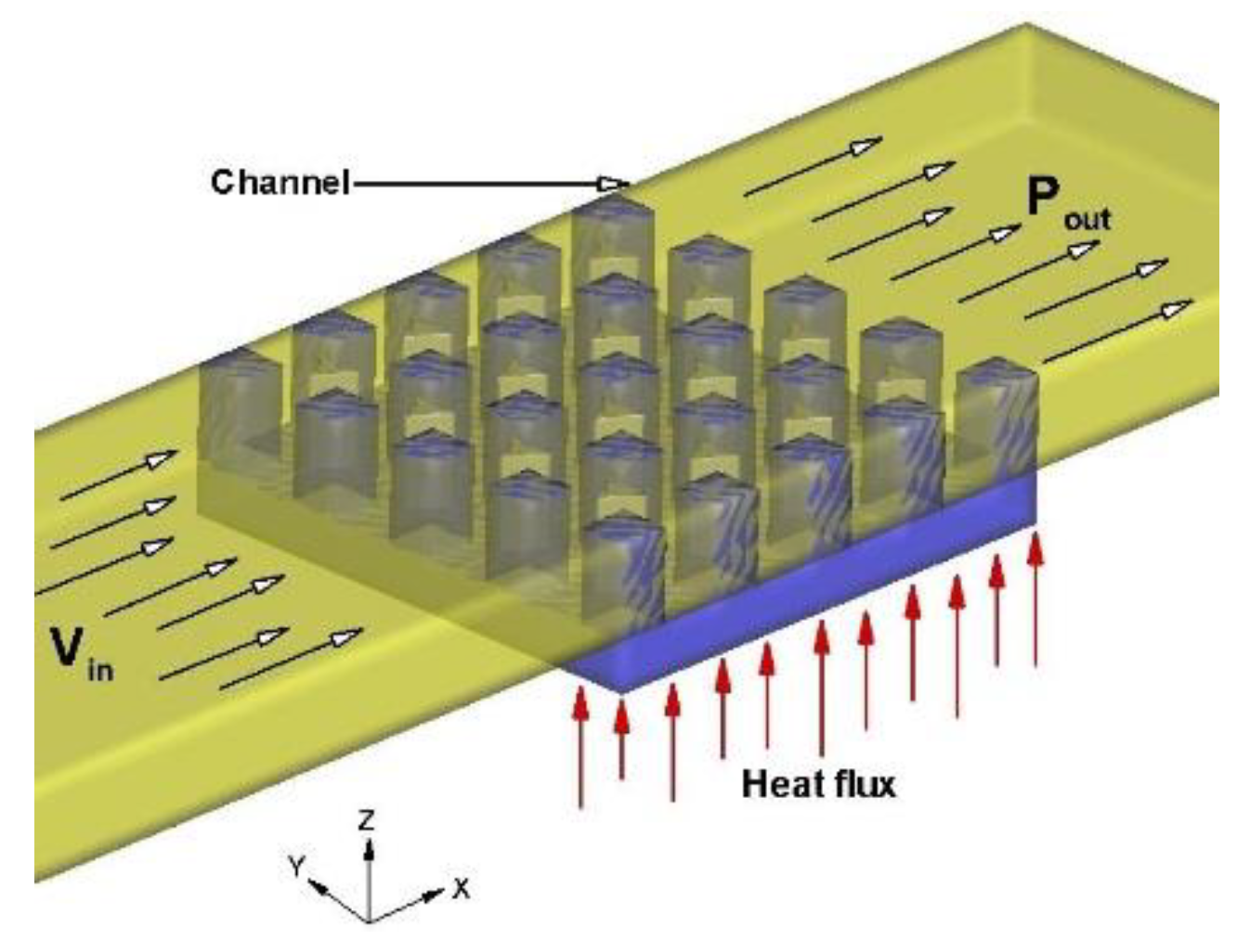
Open channel
To create the
by-pass effect in the channel design, on top and sides of the heat sink finned, it not restricted to that the entire amount of flow to circulate through of the heat sink model.
Figure 3 shows the described it.
Closed channel
The top and the floor of the channel design show that on the heat sink model, there is not space created (
by-pas effects) through which the flow passes freely, thereby forcing the flow to pass completely through the deflectors implemented and the heat sink model.
Figure 4 shows the described.
2.1. Experiments Configuration Computational Analysis
A model was established. It consists of a heat sink prototype, with a base to which a heat flux Q = 8500 W/m2 is applied. To avoid system, overheat a flow of air is directed about the fins of the heat sink model.
Steady-state
Incompressible flow
Heat sink base, uniform heat flux, Q = 8500 W/m2
Heat transfer by radiation is not considered
Constant properties
2.2. Governing Equations
In the thermal problem of computational fluid dynamics, the equations governing the whole system are continuity, momentum, and energy for fluids, and only the energy formula for solids.
For computational fluid-dynamic thermal problems, the equations that govern the entire system are the Continuity, Momentum and Energy equations for the fluid, for the solid only the equation of the Energy. Equation (1) shows the simplified equation of continuity on rectangular coordinates for the fluid.
Through Equations (2)-(4) it shown the simplified coordinate momentum equations rectangular for each of the cartesian coordinates of the fluid domain.
Finally, Equations (6) indicate the simplified coordinate energy equations rectangular, for the solid and the fluid, respectively.
The average Nusselt number Eq. (7), was determined as:
Where
in Eq. (8), is obtained by deduction of
The friction coefficient Eq. (9), was determined as:
Geometric parameter described are shown in
Figure 5.
Also considered:
Air temperature at the entrance of the channel is the ambient temperature (300 K).
A constant heat flux is supplied to the base of the heat sink model.
Turbulent model k – є (RNG).
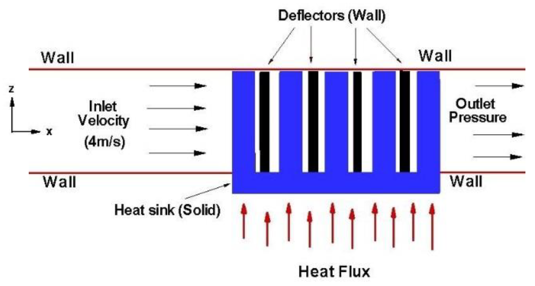
The k – є (RNG) model is implemented on renormalization of the group theory. The boundary conditions listed above are schematized in
Figure 6.
The equations used in this model are like the standard k–є model but with some refinements that allow its application for low and high Reynolds numbers. Solves two closure equations, for the turbulent kinetic energy (k) and other for the velocity of turbulent dissipation (є).
2.3. Convergence Criterion
To assure the convergence, were to set up the residuals of the equations of continuity, velocity, and 𝑘 − 𝜖 data value of convergence of 1 ×10⁻³, while for the equation energy, the residual is set to a convergence value of 1 ×10⁻⁶.
The mesh is created by tetrahedral and triangular elements considering both solid and fluid domains, providing confidence in the results; the fluid domain is discretized in small cells or finite volume called elements that form a mesh. The density of nodes or elements change from one region to another, accumulating a greater number of them in areas where large variations are expected in some variable. It is important to know which areas expect higher gradients and to consider if a finer mesh is important to refine the mesh, such as in the contact area between the fin-deflectors implemented and fluid used in the medium suitable. The quality of the mesh largely determines the reliability of the results.
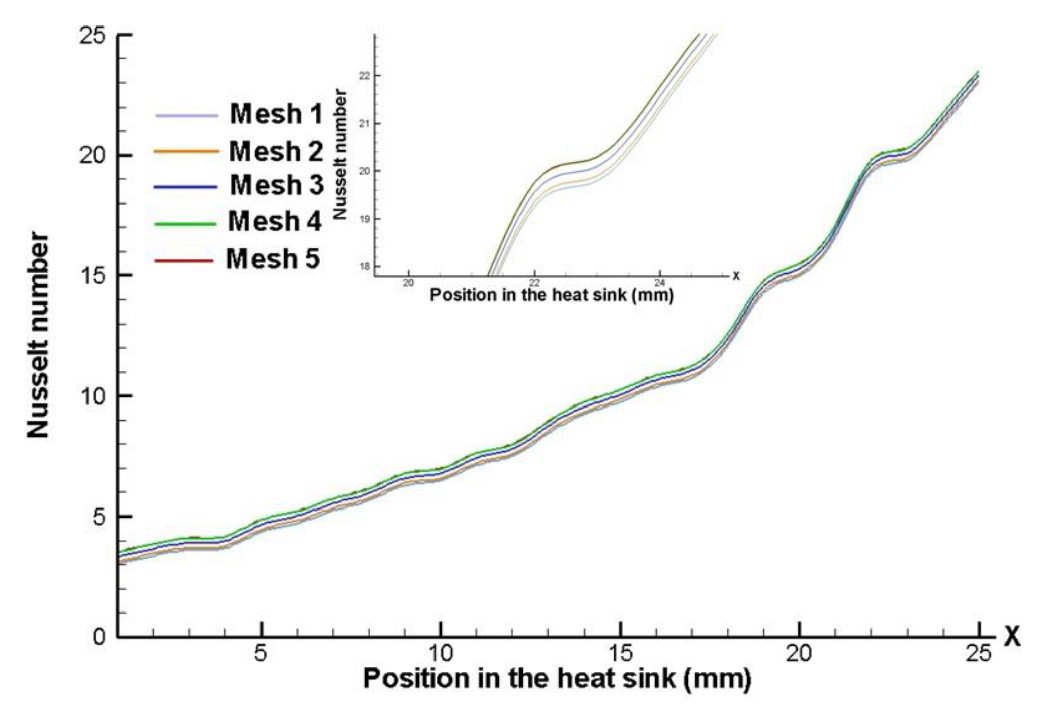
To better understand the minimization error generated by the mesh, a Mesh Sensibility Analysis is carried out. This analysis is bases of the fact of generating an “initial” mesh in the model and getting the numerical solution for the specific boundary and operating conditions. Once the solution is computed, the number of elements of the mesh is increased (the number of elements may be increased twice the number of elements used in the “initial” mesh), generating a “second” mesh. Then, the model is solved using this improved mesh considering the same boundary and operating conditions, the results for each solution are then compared and the difference is evaluated. This process is repeated until the difference can be assumed as negligible.
In this work, the “initial” mesh was formed by 320,000 tetrahedral and triangular elements (Mesh 1). An increase of two times is done in the mesh along each axial direction (x-, y- and z-axis), generating a second mesh of elements 576,000 (Mesh 2). Once the solutions were computed and compared according to the iterative process, is taken the decision of generating three subsequent meshes (Mesh 3, Mesh 4 and Mesh 5), having 980,000, 1,660,000 and 2,850,000 elements, respectively.
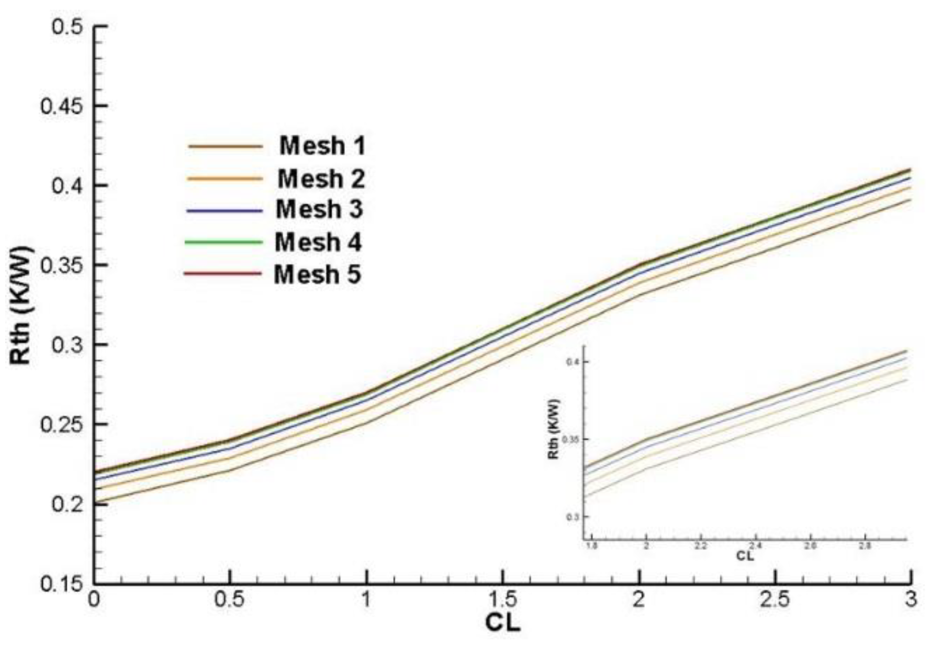
Figure 7 and
Figure 8 presents the Nusselt number and global thermal resistance variations for the five meshes. The results show that the difference generated by “meshing” is negligible when Mesh 3 is used. Analyzing the curves, it is observed that the Nusselt number and global thermal resistance variations between Mesh 4 and Mesh 5 are negligible (0,05 and 0,01 K/W, respectively).
3. Results and Discussion
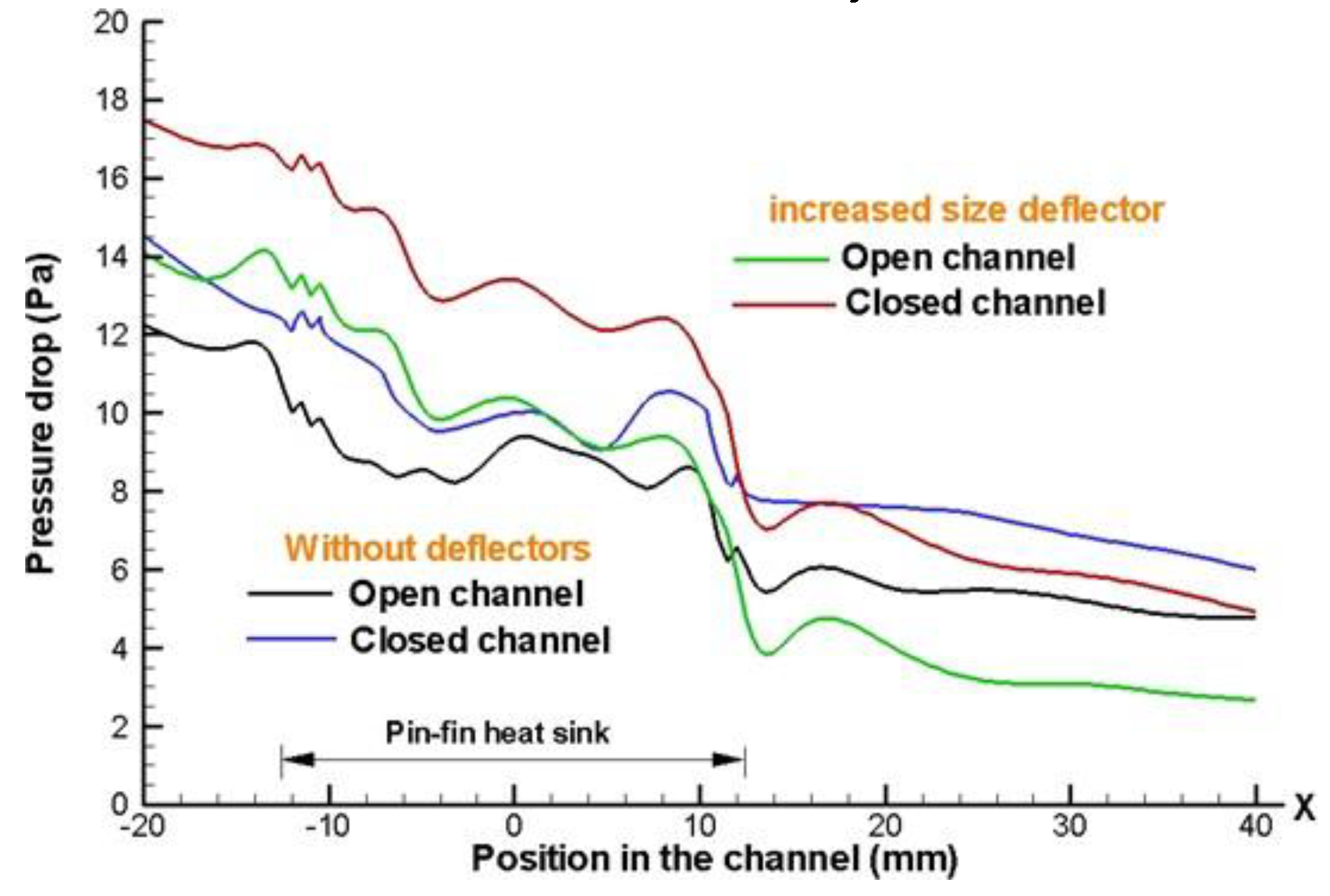
The results the simulation for the heat sink were obtained by drawing a line at the center of the heat sink and are shown in the next graphics. The accelerating flows inside the heat sink channel and the fin-deflectors implemented produces a pressure drop between the channel entrance and exit region.
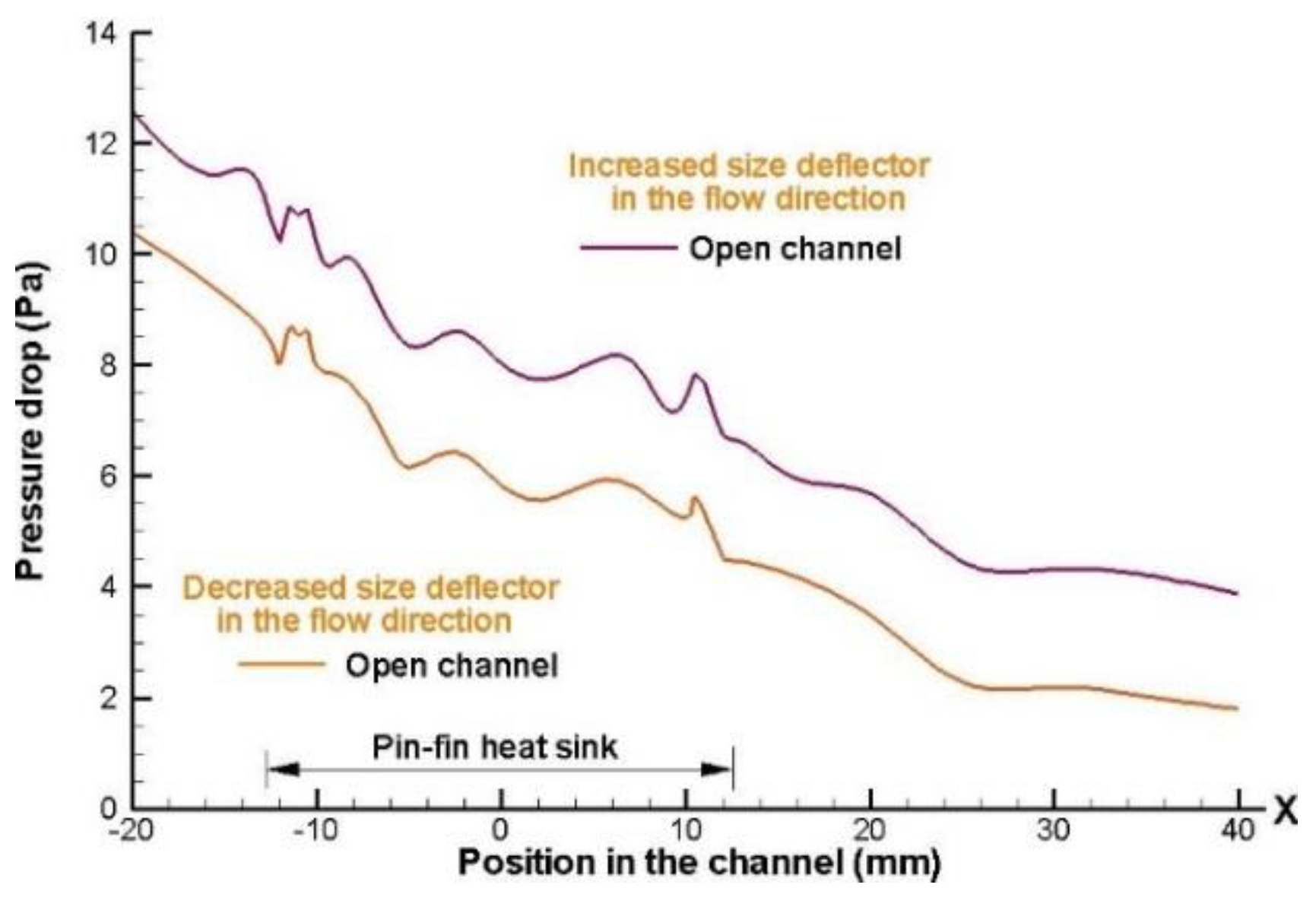
Figure 9,
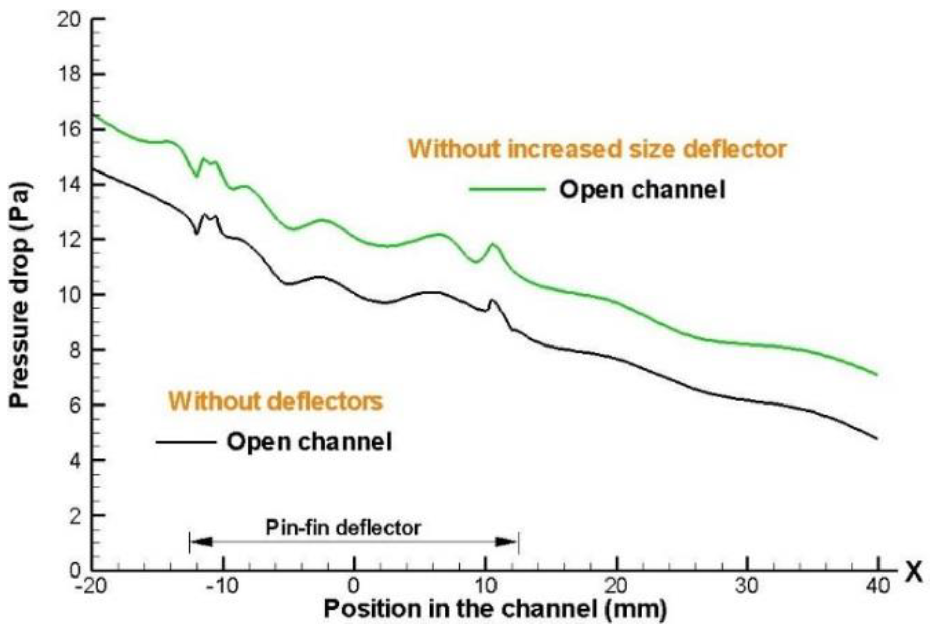
Figure 10,
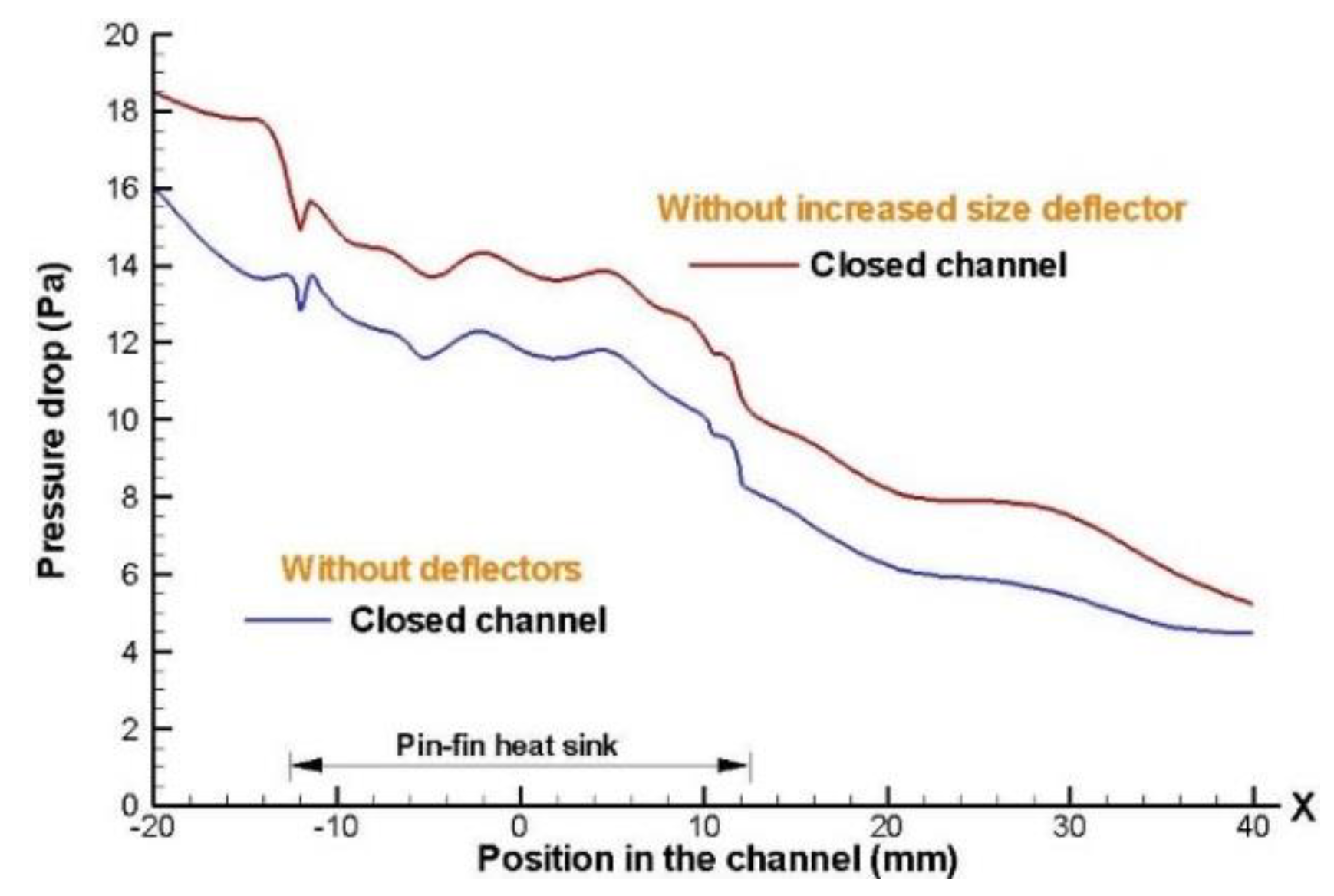
Figure 11 and
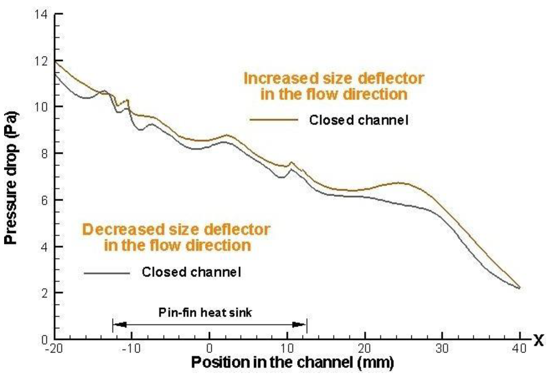
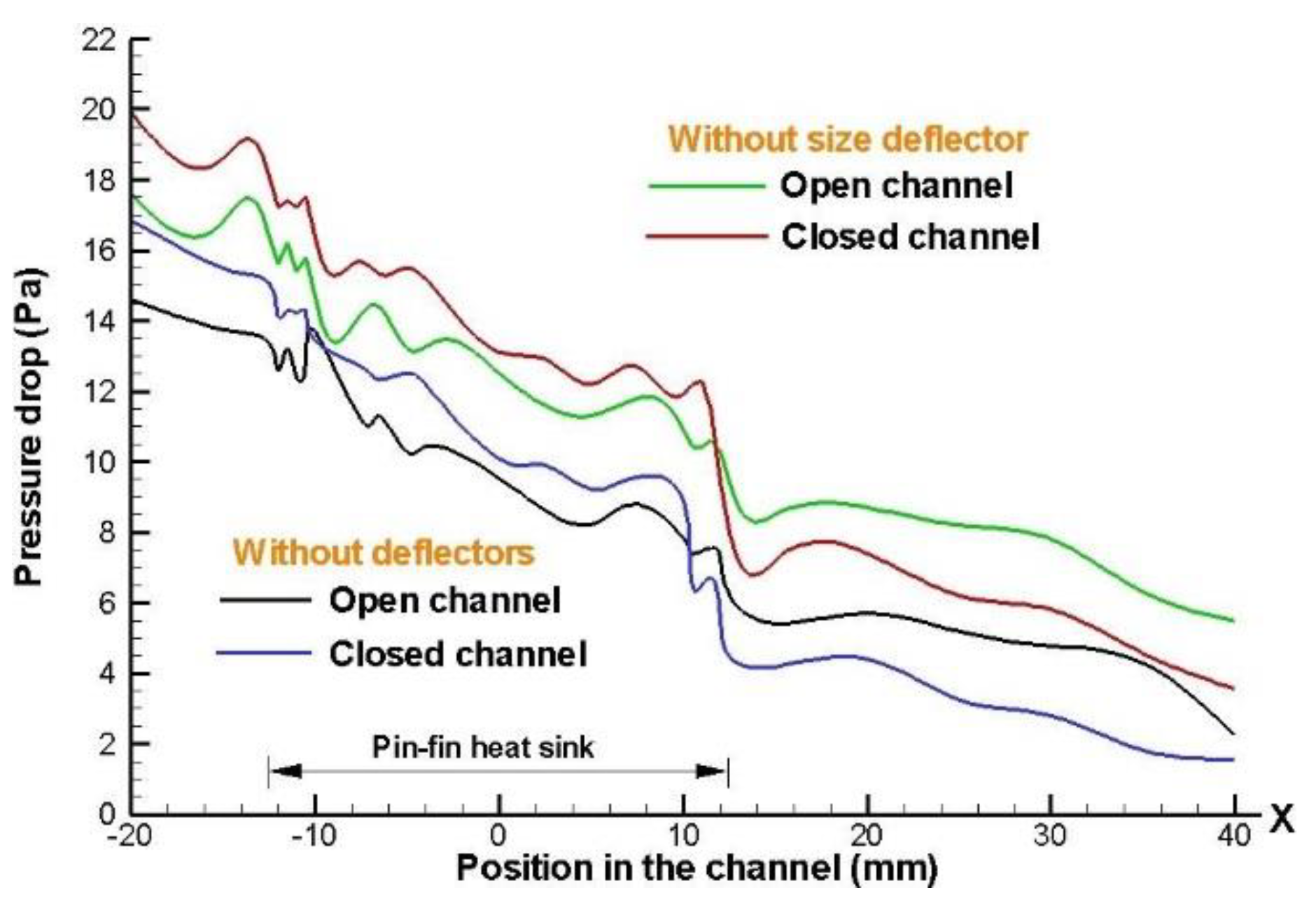
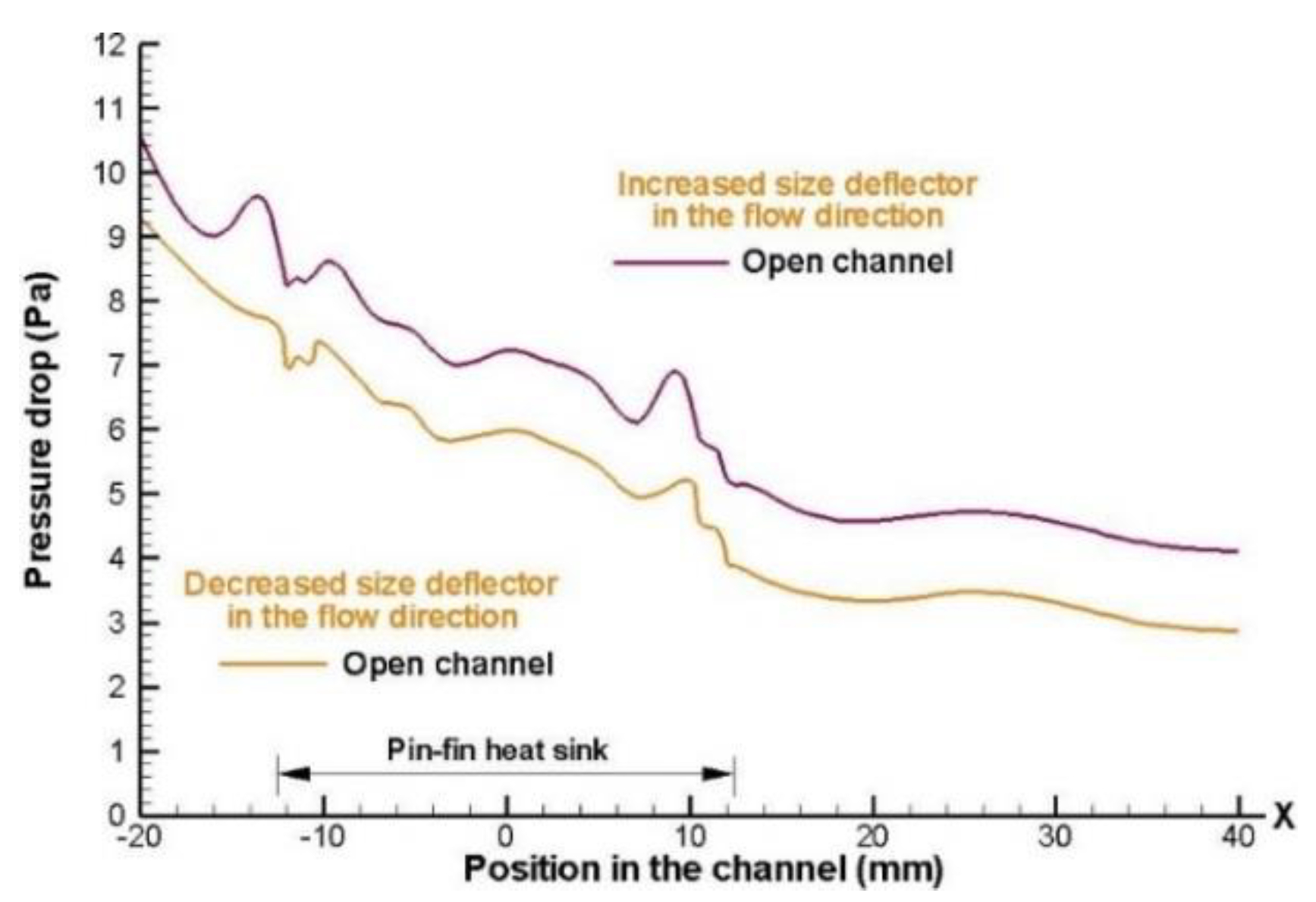
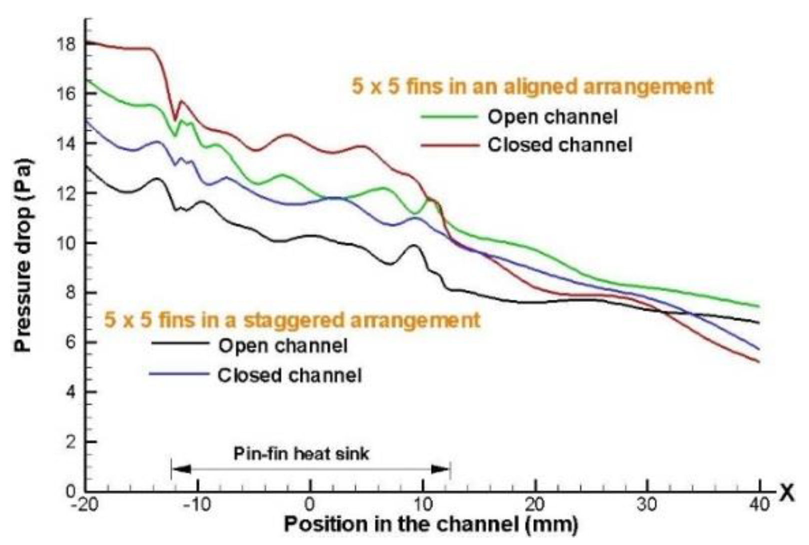
Figure 12 show the pressure distribution along the duct, with an inlet velocity of 4 m/s for heat sink model in aligned and staggered configurations of 5 x 5 and 8 x 8 respectively, making a comparison between both channels (open and closed), also is shown the effect of the implementation of the deflectors inside the system. As a result expected, it is observed that the pressure is higher at the entrance of conduct the heat sink model and decreases through path downstream.
Also, the effects of the deflectors collocated for aligned and staggered configurations, both for open channel and closed channel designs are shown in
Figure 9,
Figure 10,
Figure 11 and
Figure 12. When deflectors were used in the closed channel design, the pressure drop trough the pin-fin heat sink arrangement increases the pumping energy required to cool the heat sink model.
The
Figure 9 and
Figure 10 show that the trend is consistent increasing the size of the deflectors implemented along the heat sink model. However, has a higher pressure drop for the case that presents a closed channel and the deflectors size increase along the direction flow. This is because the airflow circulating through the heat sink model, it encounters in this path with the presence of increased resistance to flow, as well as an increase in the size of the deflectors collocated that hindering the circulation of the airflow freely.
Figure 11,
Figure 12 and
Figure 13 show a pressure drop greater for the 5 x 5 fins configurations in aligned arrangements, as expected and for the case where the height of the deflectors implemented is kept constant, which are positioned along and within the heat sink model. A higher pressure drop is obtained when the height of deflector increases in closed channel design, due to increasing contact of airflow with deflector elements.
Figure 14 show the scenario in which the size deflector increases and decreases, with height of the deflectors implemented in the flow direction, a higher-pressure drop is obtained when the height of deflector increases in closed channel design, due to enhancement contact of airflow with each deflector element of system.
Figure 15 shows that using a staggered arrangement results in a decrease in the drop pressure for the two channel designs (open and closed). Nevertheless, when there is an open channel design, the air that supplied circulate more freely through medium, but when the flow is forced to pass entirely within the heat sink model, (which case is the closed channel design); it shows a greater pressure drop, due to the presence of the deflectors inside the heat sink model).
Figure 16 shows a higher drop pressure for the case that increased size deflector implemented. The increase in drop pressure a cross the heat sink inlet, is due to the strangulation of air flow to reach the fins and begin contact with each deflector element of system.
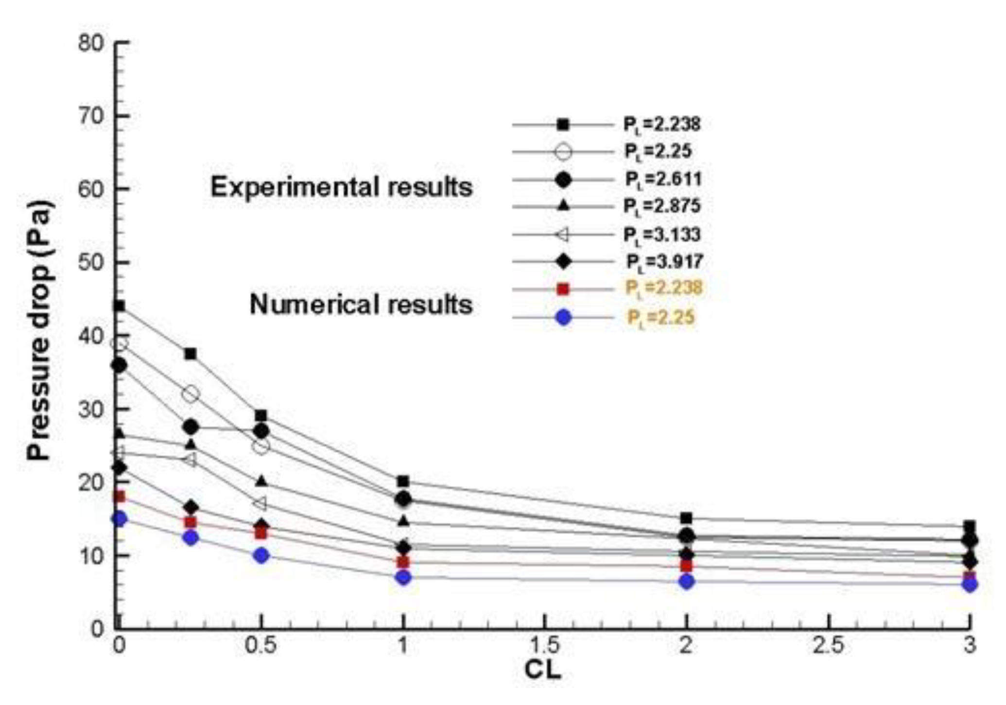
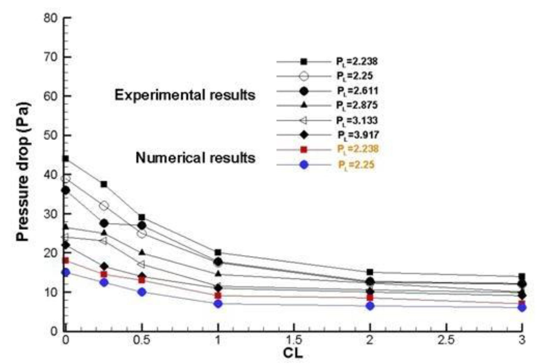
Figure 17, shows that the pressure drop for different rates clearance (CL), presents a similar behavior in the experimental and numerical cases, this is due a that the pressure drop decreases over the distance created on the upper heat sink model (by-pass). For effect by-pass in the drop pressure, the pressure drop is lower, because to that the amount of flow passing by the fins is reduced. The pressure drop measured is acceptable, according to the predicted values and the increasing contraction and expansion pressure losses at the channel designs (inlet and outlet). In general, the total heat sink model pressure drop depends on four major factors: the friction factors, the heat sink geometry, the velocities approach and of the air within channel respectively.
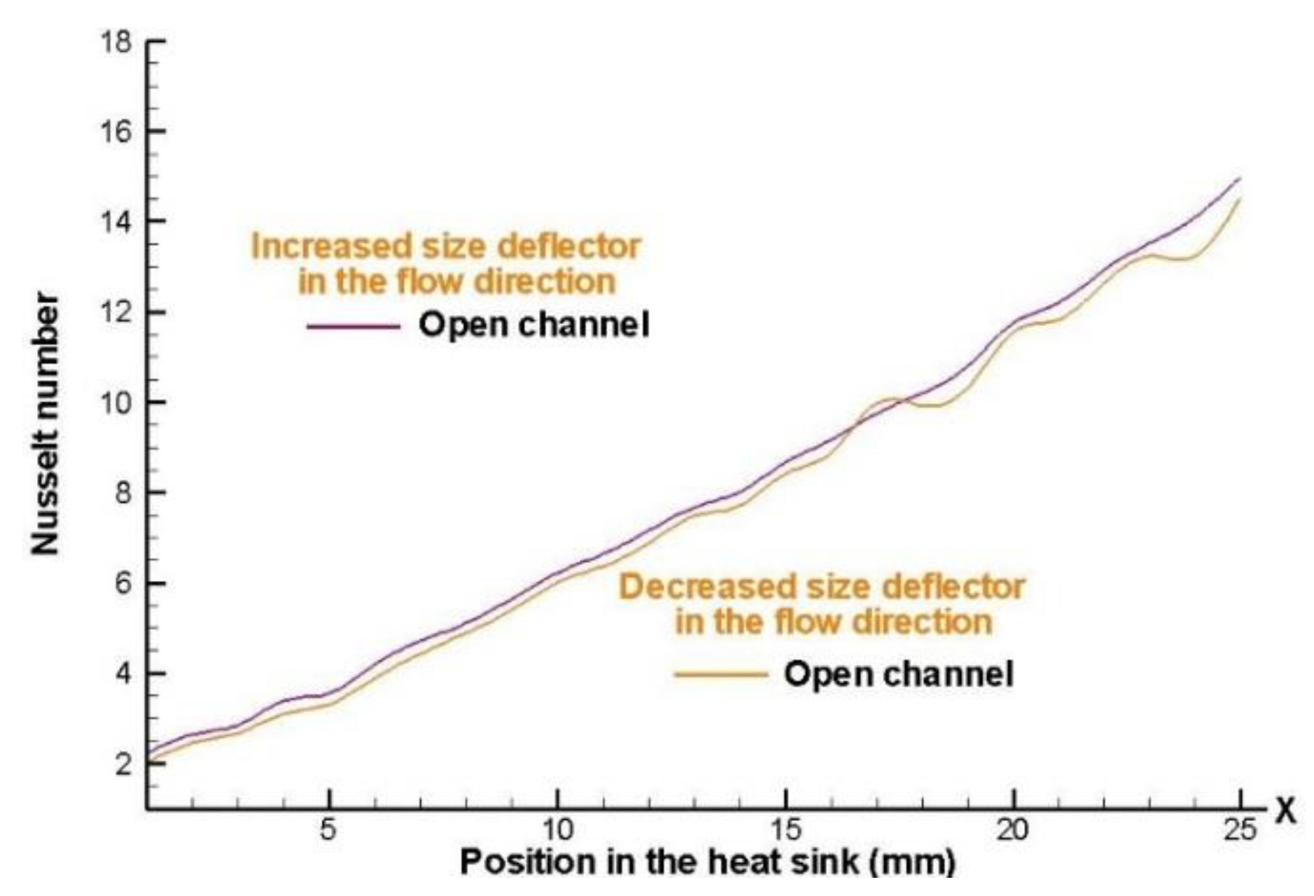
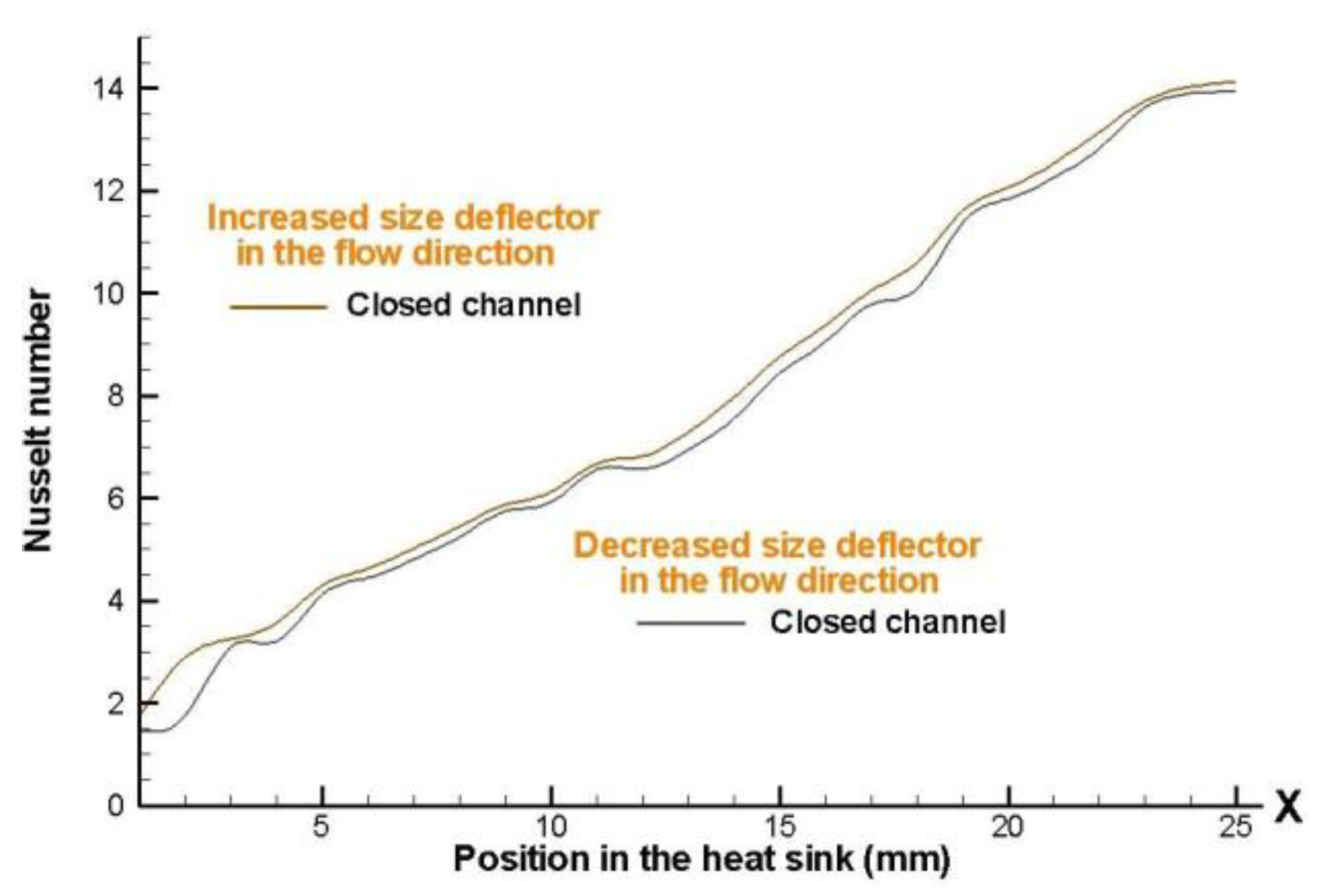
Figure 18 and
Figure 19 show the effect which occurs at admit in the Nusselt number, increase and decrease the height of the deflectors element, presenting a higher heat removal for the 8 x 8 fins in a staggered arrangement, in both staggered arrangement the heat removal is higher by about 6% when there is an increase in the height of the deflectors in the air flow direction. It is also noted that the graphics intersect in certain areas of the heat sink models, this is because to that in these areas the size of the deflectors is approximately similar for both cases.
Clearly the value of the Nusselt number increases along the heat sink model; this is mainly caused by the acceleration of the fluid that is leaving the pin-fin and the section of deflector elements and also by the instability that is generated when the air is passing through. These results are obtained via the numerical results.
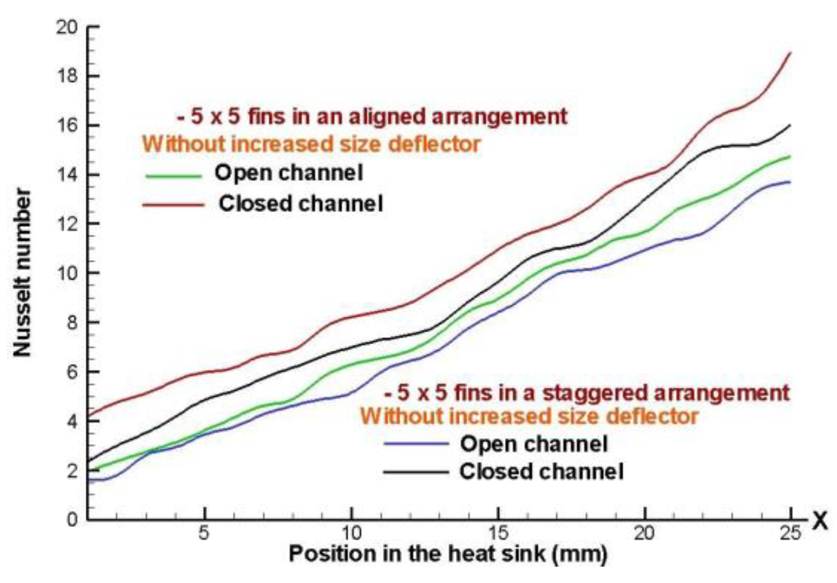
Figure 20 shows a comparison, in the when for both arrangement is greater heat dissipation for a closed channel design. However, the greater heat dissipation is presents for the cases of aligned arrangements. The 5 x 5 fin configurations in staggered arrangement, presents less wetted area, because this arrangement has fewer fins and thus less conduct area, decreasing the efficiency of the heat sink model.
It must be remembered that in an open channel there will be free flow on the sides of the dissipator, and for a closed channel design, the flow is forced to circulate through the elements deflector and inside the heat sink model, thus achieving an increase in the Nusselt number.
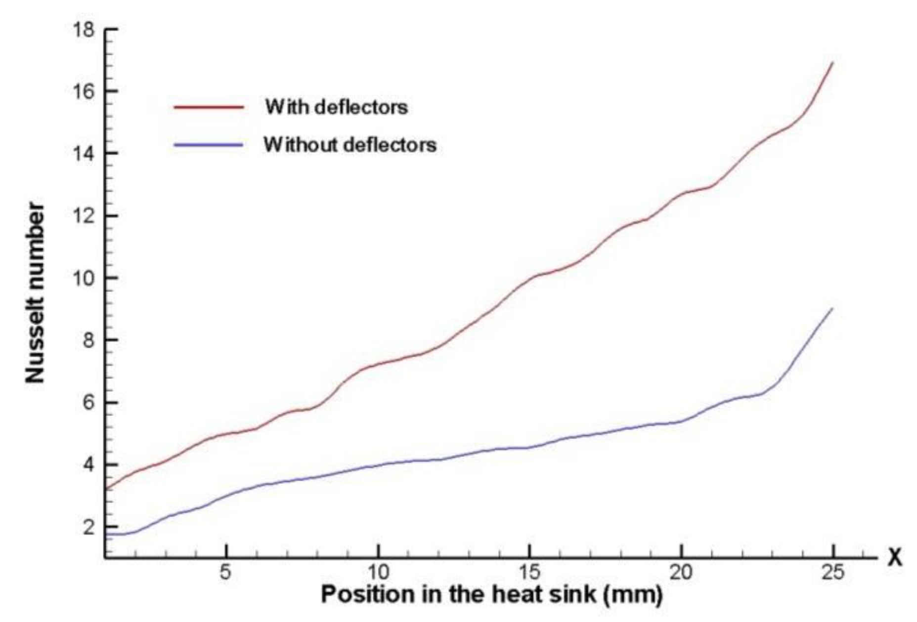
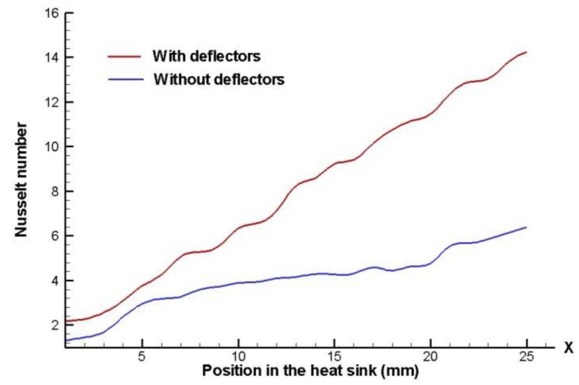
Figure 21 and
Figure 22 shown comparisons of the local Nusselt number with and without deflector elements, for both aligned arrangements and closed channel design for a rate clearance, CL=0.
Thus, by using deflector elements there is clearly an increase of the local Nusselt number; this is due to the acceleration of the fluid caused by the deflector, and to the fact that the flow is being directed towards areas that otherwise will have stagnation of the airflow; the largest local Nusselt number appears at the end of the pin-fin heat sink model. At the entrance of the pin-fin arrangement the Nusselt number is the same for both cases, and it has a higher increment through the heat sink model when the deflector elements are used in an aligned configuration.
It is clear that the Nusselt number improves with the presence of deflector elements for both pin-fin heat sinks arrangements (aligned and staggered), but the Nusselt number is larger when there is an 8 x 8 fin configuration and the channel design is closed.
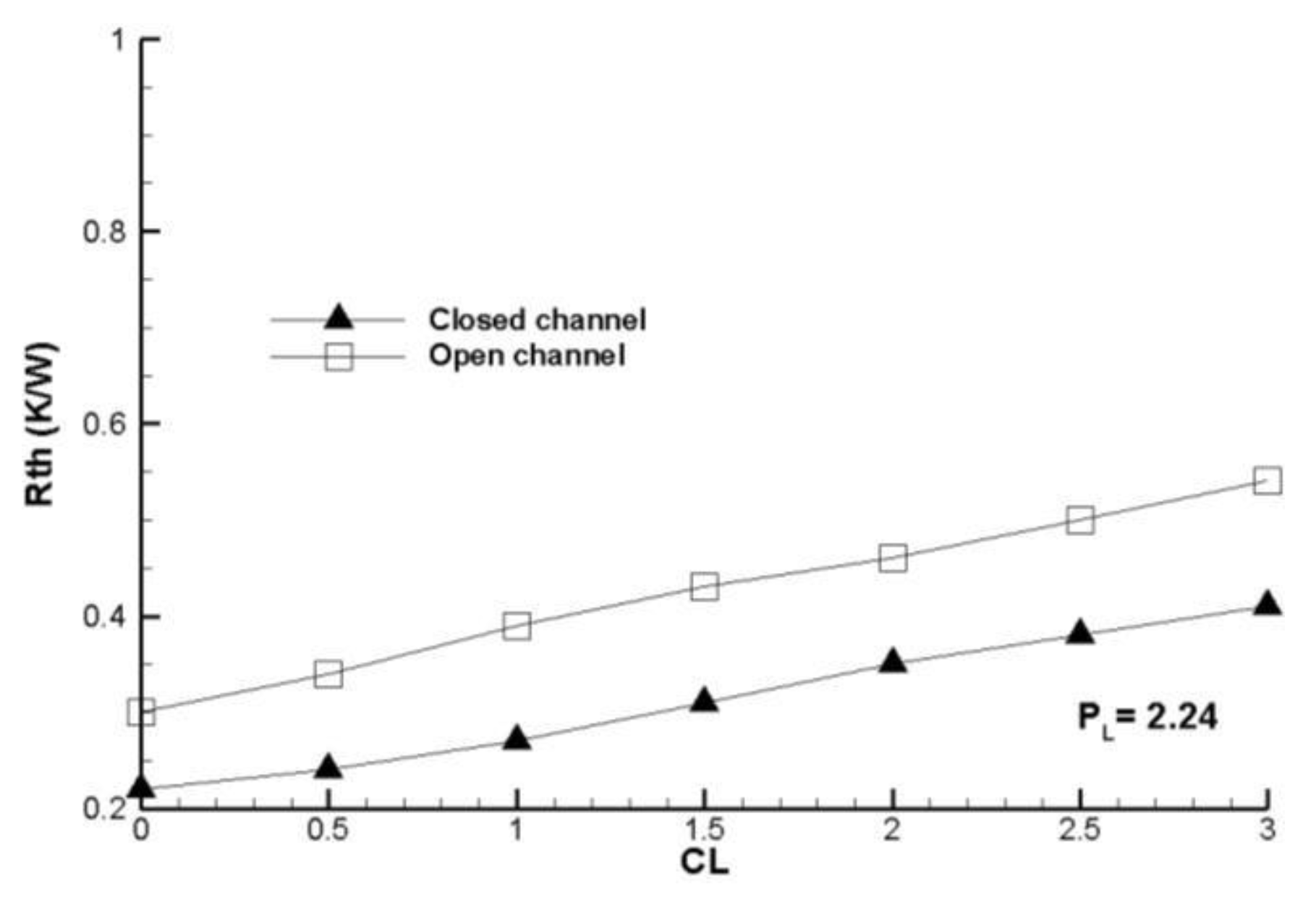
Figure 23 and
Figure 24 show that comparison between arrangements aligned and staggered, it is presents that the thermal resistance is higher for the staggered arrangement, this means that in these types of arrangements the heat removal is lower.
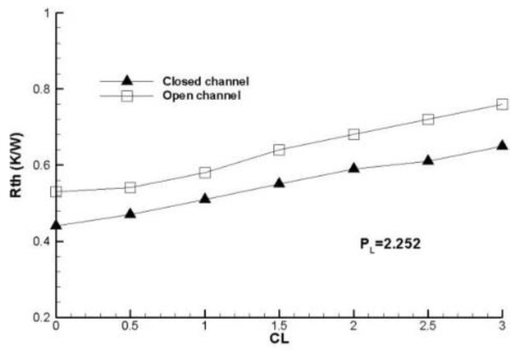
It is expected that the global thermal resistance increases according to the rate clearance is higher, this is due to the fact that a fraction of the air goes to the top of the fins (bypass); this is also greater when the distance between the fins is greater. The thermal resistance increases according the rate clearance is increased, as well as a lower thermal resistance is presents for the case 8 x 8 fins arrangement because this provides the most amount wetted area.
The amount minor of wetted area is shown is the 5 x 5 fins arrangement and the configuration that present a fewer global thermal resistance is the 8 x 8 fins arrangement, because to that is present a smaller spacing between fins.
Figure 25 shows experimental and numerical results that the thermal resistance tends to increase as a function of the clearance ratio (CL), as expected. It also has a lower thermal resistance for case where decreases the height of the fin which is the numerical case.
This leads to the conclusion that global thermal resistance increases with decreasing wetted area of the fins, or to decrease the convection coefficient and is a consequence of having fewer wetted area of the fins in the heat sink.
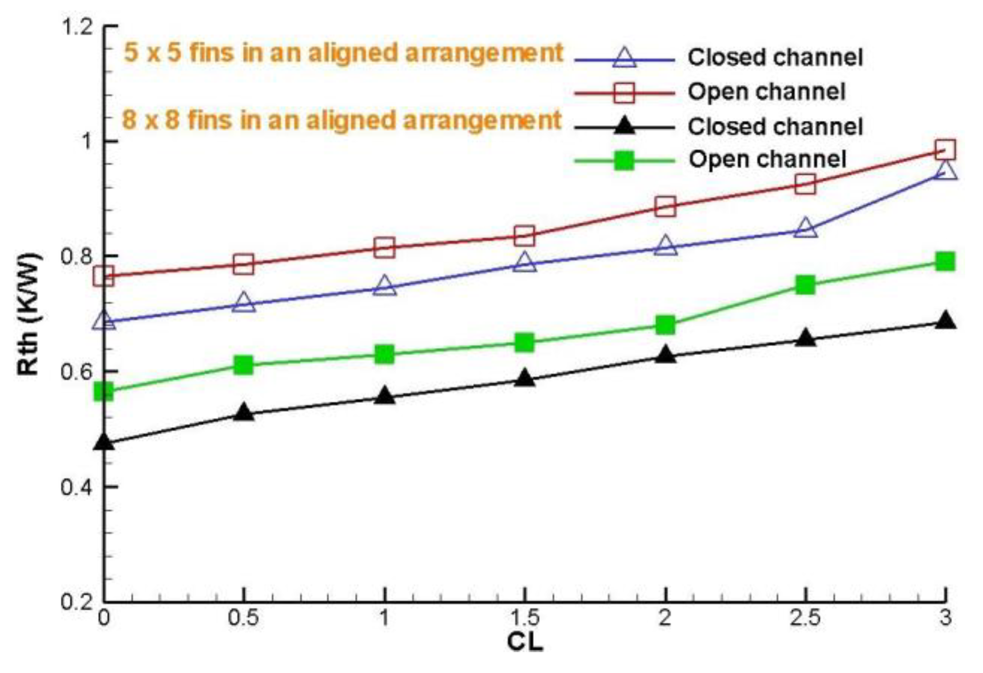
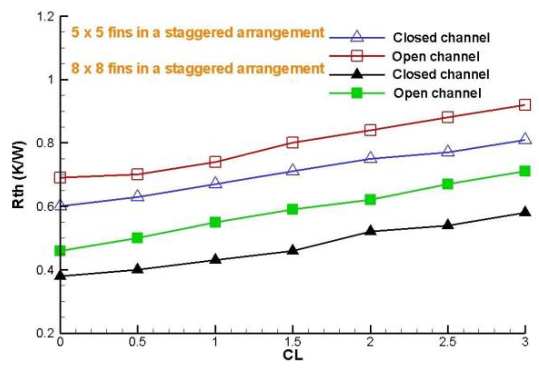
Figure 26 and
Figure 27 show that for both cases the thermal resistance results lower for the aligned arrangements of 8 x 8 fins, for both cases in closed channel design. The close channel was designed with the target that the by-pass effect is not present at the top and the sides of the heat sink, in order to force the entire air flow to pass through the deflector elements placed within of heat sink finned and thereby is present a higher heat removal.
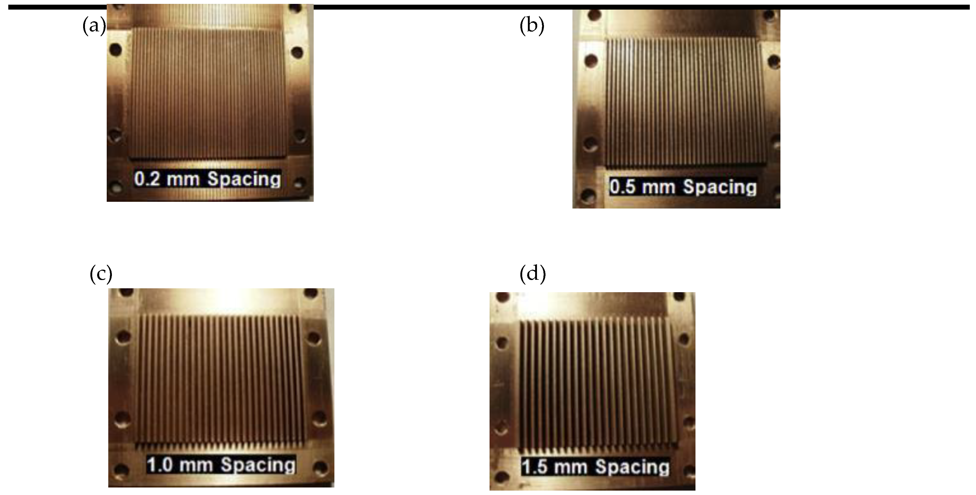
Figure 1.
Heat sinks built at different distances.
Figure 1.
Heat sinks built at different distances.
Figure 2.
Illustration of the heat sink geometry analyzed: (a) side view with a top by-pass channel design, (b) top view of the closed channel design in arrangement aligned of deflectors implemented, (c) top view of the open channel design in arrangement of staggered deflectors collocated,(d) shape of deflector implemented, (e) 3D view of the heat sink model, (f) and (g) views 3D lateral and frontal respectively of the heat sink model with size increased deflector, (h) and (i) view 3D lateral and frontal respectively of the heat sink model with size decreased deflector. At the same time, the size of the rectangular fin profile, remained unchanged. The dimensions that were used in the analysis are shown in
Table 1. These are the optimal parameters were studied in the technical literature [
24].
Figure 3.
View 3D for an open channel design.
Figure 3.
View 3D for an open channel design.
Figure 4.
View 3D for a closed channel design.
Figure 4.
View 3D for a closed channel design.
Figure 5.
Geometric parameters.
Figure 5.
Geometric parameters.
Figure 6.
Scheme of the boundary conditions for computational analysis of model.
Figure 6.
Scheme of the boundary conditions for computational analysis of model.
Figure 7.
Mesh Sensibility Analysis for the Nusselt number.
Figure 7.
Mesh Sensibility Analysis for the Nusselt number.
Figure 8.
Mesh Sensibility Analysis for the Global thermal resistance.
Figure 8.
Mesh Sensibility Analysis for the Global thermal resistance.
Figure 9.
Effect of the deflectors implemented in open channel design on the pressure distribution along of the heat sink model, with an inlet velocity of 4 m/s, for 5 x 5 fin configurations in aligned arrangement.
Figure 9.
Effect of the deflectors implemented in open channel design on the pressure distribution along of the heat sink model, with an inlet velocity of 4 m/s, for 5 x 5 fin configurations in aligned arrangement.
Figure 10.
Effect of deflectors implemented in closed channel design on the pressure distribution along of the heat sink model, with an inlet velocity of 4 m/s, for 5 x 5 fin configurations in aligned arrangement.
Figure 10.
Effect of deflectors implemented in closed channel design on the pressure distribution along of the heat sink model, with an inlet velocity of 4 m/s, for 5 x 5 fin configurations in aligned arrangement.
Figure 11.
Effect of the deflectors implemented in open channel design on the pressure distribution along the heat sink model, with an inlet velocity of 4 m/s, for 5 x 5 fin configurations in aligned arrangement.
Figure 11.
Effect of the deflectors implemented in open channel design on the pressure distribution along the heat sink model, with an inlet velocity of 4 m/s, for 5 x 5 fin configurations in aligned arrangement.
Figure 12.
Effect of the deflectors implemented in closed channel design on the pressure distribution along the heat sink model, with an inlet velocity of 4 m/s, for 5 x 5 fin configurations in aligned arrangement.
Figure 12.
Effect of the deflectors implemented in closed channel design on the pressure distribution along the heat sink model, with an inlet velocity of 4 m/s, for 5 x 5 fin configurations in aligned arrangement.
Figure 13.
Effect of the deflectors implemented in open and closed channel design on the pressure distribution along the heat sink model, with an inlet velocity of 4 m/s, for 8 x 8 fin configurations in aligned arrangement.
Figure 13.
Effect of the deflectors implemented in open and closed channel design on the pressure distribution along the heat sink model, with an inlet velocity of 4 m/s, for 8 x 8 fin configurations in aligned arrangement.
Figure 14.
Effect to collocate deflectors in open channel design on pressure distribution along of heat sink model, with an inlet velocity of 4 m/s, for 5 x 5 fin configurations in staggered arrangement.
Figure 14.
Effect to collocate deflectors in open channel design on pressure distribution along of heat sink model, with an inlet velocity of 4 m/s, for 5 x 5 fin configurations in staggered arrangement.
Figure 15.
Effect of deflectors implemented in closed channel design on the pressure distribution along of the heat sink model, with an inlet velocity of 4 m/s, for 5 x 5 fin configurations in a staggered arrangement.
Figure 15.
Effect of deflectors implemented in closed channel design on the pressure distribution along of the heat sink model, with an inlet velocity of 4 m/s, for 5 x 5 fin configurations in a staggered arrangement.
Figure 16.
Effect to collocate deflectors in open and closed channel designs on the pressure distribution along of the heat sink model, with an inlet velocity of 4 m/s, for 8 x 8 fin configurations in a staggered arrangement.
Figure 16.
Effect to collocate deflectors in open and closed channel designs on the pressure distribution along of the heat sink model, with an inlet velocity of 4 m/s, for 8 x 8 fin configurations in a staggered arrangement.
Figure 17.
Experimental and numerical results [
5] without deflectors element collocated for total pressure drop vs different rate clearance (CL) with an inlet velocity of 4 m/s and different PL´s, with H=22.5 mm and H=4.5 mm.
Figure 17.
Experimental and numerical results [
5] without deflectors element collocated for total pressure drop vs different rate clearance (CL) with an inlet velocity of 4 m/s and different PL´s, with H=22.5 mm and H=4.5 mm.
Figure 18.
Local Nusselt number with an inlet velocity of 4 m/s, for a 8 x 8 fin configurations in staggered arrangement.
Figure 18.
Local Nusselt number with an inlet velocity of 4 m/s, for a 8 x 8 fin configurations in staggered arrangement.
Figure 19.
Local Nusselt number with an inlet velocity of 4 m/s, for a 5x 5 fin configurations in staggered arrangement.
Figure 19.
Local Nusselt number with an inlet velocity of 4 m/s, for a 5x 5 fin configurations in staggered arrangement.
Figure 20.
Comparison of local Nusselt number for 5 x 5 fin configuration in aligned and staggered arrangements along of the heat sink model, with an inlet velocity of 4 m/s.
Figure 20.
Comparison of local Nusselt number for 5 x 5 fin configuration in aligned and staggered arrangements along of the heat sink model, with an inlet velocity of 4 m/s.
Figure 21.
Effect of the deflector elements on the Nusselt number along the position in the heat sink model, with an inlet velocity of 4 m/s, for a 5 x 5 fin configuration in aligned arrangement.
Figure 21.
Effect of the deflector elements on the Nusselt number along the position in the heat sink model, with an inlet velocity of 4 m/s, for a 5 x 5 fin configuration in aligned arrangement.
Figure 22.
Effect of the deflector elements on the Nusselt number along the position in the heat sink model, with an inlet velocity of 4 m/s, for a 8 x 8 fin configuration in aligned arrangement.
Figure 22.
Effect of the deflector elements on the Nusselt number along the position in the heat sink model, with an inlet velocity of 4 m/s, for a 8 x 8 fin configuration in aligned arrangement.
Figure 23.
Global thermal resistance with different rate clearance, for 8 x 8 fin configurations and deflectors collocated in a staggered arrangement.
Figure 23.
Global thermal resistance with different rate clearance, for 8 x 8 fin configurations and deflectors collocated in a staggered arrangement.
Figure 24.
Global thermal resistance with different rate clearance, for 5 x 5 fin configuration and deflectors collocated in a staggered arrangement.
Figure 24.
Global thermal resistance with different rate clearance, for 5 x 5 fin configuration and deflectors collocated in a staggered arrangement.
Figure 25.
Numerical results for thermal resistance vs clearance (CL) for H=22.5 mm, H = 4.5 mm and an inlet velocity of 4 m/s, in a closed channel design.
Figure 25.
Numerical results for thermal resistance vs clearance (CL) for H=22.5 mm, H = 4.5 mm and an inlet velocity of 4 m/s, in a closed channel design.
Figure 26.
Comparison global thermal resistance for different clearance ratio, decreased size deflector in the air flow direction for both arrangements.
Figure 26.
Comparison global thermal resistance for different clearance ratio, decreased size deflector in the air flow direction for both arrangements.
Figure 27.
Comparison global thermal resistance for different clearance ratio, decreased size deflector in the air flow direction for both cases.
Figure 27.
Comparison global thermal resistance for different clearance ratio, decreased size deflector in the air flow direction for both cases.
Table 1.
Dimensions and configurations of the pin-fin heat sink model and positions of deflectors implemented in the model.
Table 1.
Dimensions and configurations of the pin-fin heat sink model and positions of deflectors implemented in the model.
| Parameter [mm] |
5x5 fin configurations aligned in staggered arrangements |
8x8 fin
configurations aligned in staggered arrangements |
| a |
2.5 |
1.5 |
| b |
3.13 |
1.86 |
| B |
2.5 |
2.5 |
| C |
25 |
25 |
| d |
12.5 |
12.5 |
| e |
1.125, 2.25, 3.375, 4.5 |
0.642, 1.284, 1.926, 2.568, 3.21, 3.852, 4.5 |
| H |
4.5 |
4.5 |
| L |
0, 2.25, 4.5, 6.75, 9, 11.25, 13.5 |
0, 2.25, 4.5, 6.75, 9, 11.25, 13.5 |
| PL
|
2.252 |
2.24 |
| R |
1.22 |
0.65 |
| R |
2.24 |
1.2 |
| Rx
|
1.68 |
0.9 |
| Ry
|
1.12 |
0.6 |
