1. Introduction
With the extensive application of high-energy-storage device in human life, it is urgent to research electrode material with high energy density to develop next-generation lithium secondary battery[
1]. However, traditional commercial lithium-ion batteries are limited by the theoretical specific capacity of graphite anode (372 mAh g
-1), their energy density can no longer meet the needs of social development, such as electric vehicle, artificial intelligence and portable electronic device [
2]. Lithium metal, owing to its higher theoretical specific capacity (3860 mAh g
-1) and lowest reduction potential (-3.04 V vs. SHE), has been considered as one of the most potential anode materials for next generation lithium secondary batteries [
3,
4]. Unfortunately, the uncontrollable lithium dendrite growth caused by imhomogeneous deposition of Li+ and persistent parasitic reactions between high reactive lithium and liquid electrolyte are the two intricate barriers which seriously restrict the practical application of lithium metal anode (LMA) [
5,
6].
Tremendous effort has been devoted to overcome the lithium dendrite growth and persistent parasitic reactions of LMA, mainly including as the followed four aspects: (1) Optimizing the liquid electrolyte formulation via additives, such as lithium difluorophosphate[
7], fluorinated ether solvent[
8] or 2,2-dimethoxy-4-(trifluoromethyl)-1,3-dioxolane[
9], to improve the uniformity and compactness of SEI. (2) Utilizing inorganic, polymer or organic/inorganic composite solid-state electrolytes to inhibit lithium dendrite growth. For example, PEO based solid-state electrolyte[
10], LLZO solid-state electrolyte[
11] and PEO/LLZO composite solid-state electrolyte[
12]. (3) Employing 3D current collector, such as carbon nanotube sponge [
13,
14], carbon nanofibers matrix[
15], ZnO coated hierarchical porous carbon[
16], to reduce the local deposition current density. (4) Fabricating functional artificial layer to improve the interfacial stability of LMA/electrolyte. For example, PVDF functional layer[
17], PEO thin film[
18] and covalent organic framework[
19]. Evidently, it is the crucial to regulate the homogeneous deposition of Li
+ and prevent the direct contact of LMA and electrolyte.
Recently, construction of a robust single-ion polymeric artificial layer (SPAL) for LMA has attracted numerous attentions[
20]. Firstly, the fixed anions on the matrix of SPAL can form an efficiency Li
+ transport channel and prolong the formation of the "ion depletion layer" on the surface of LMA, which is beneficial to facilitate the homogeneous deposition of Li
+[
21]. Secondly, the compact SPAL on LMA isolates it from electrolyte, which can avoid the parasitic reactions between LMA and liquid electrolyte effectively[
22]. Furthermore, this SPAL is flexible, which is able to adapt to the volume variation during charge/discharge cycles. Song et. al. incipiently proved that the thin Nafion layer on the surface of LMA can improving the performance and durability of the lithium metal batteries[
23]. However, the low ionic conductivity of the thin Nafion layer coursed by strong binding energy between Li
+ and sulfonic acid group will discounted the Li
+ transport rate during charging and discharging processes. Therefore, Weng et. al. introduced POSS nano-particles into SPEEK layer to facilitate the dissociation of Li
+, thereby iaccelerating the ion transport[
24]. Moreover, Jiang et. al. combined the ClO
4−-decorated metal-organic framework (UiO-66-ClO
4) and flexible lithiated Nafion binder to construct biomimetic ionic channels for the artificial solid-electrolyte interfaces[
25]. However, the Li
+ conductivity of organic single-ion polymer is intrinsically low compared to the commercial electrolyte as reported[
20].
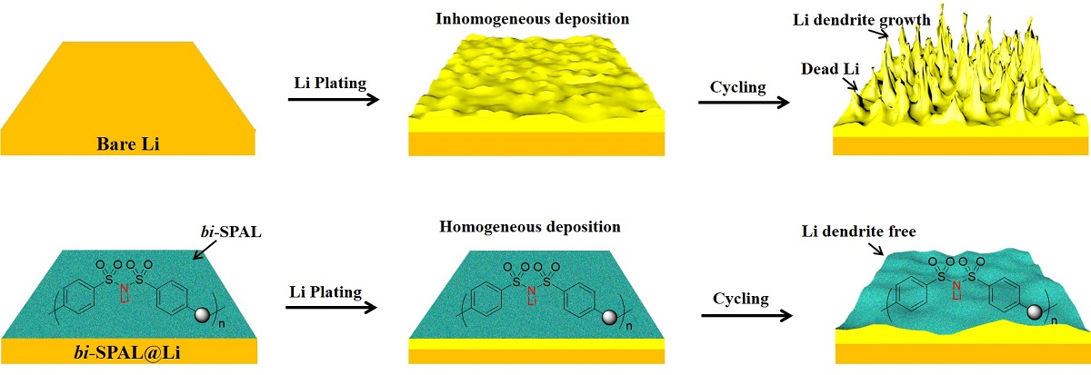
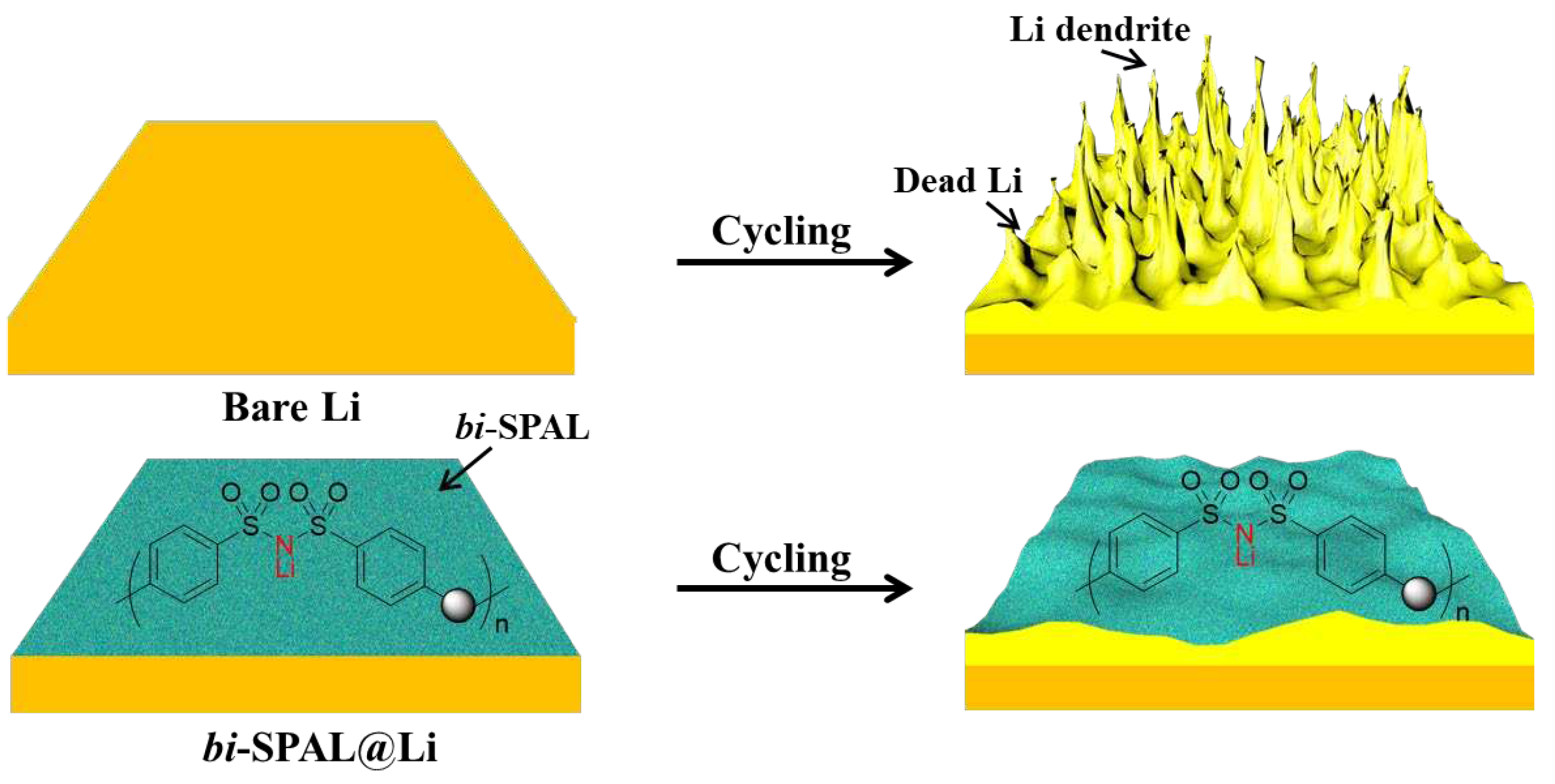
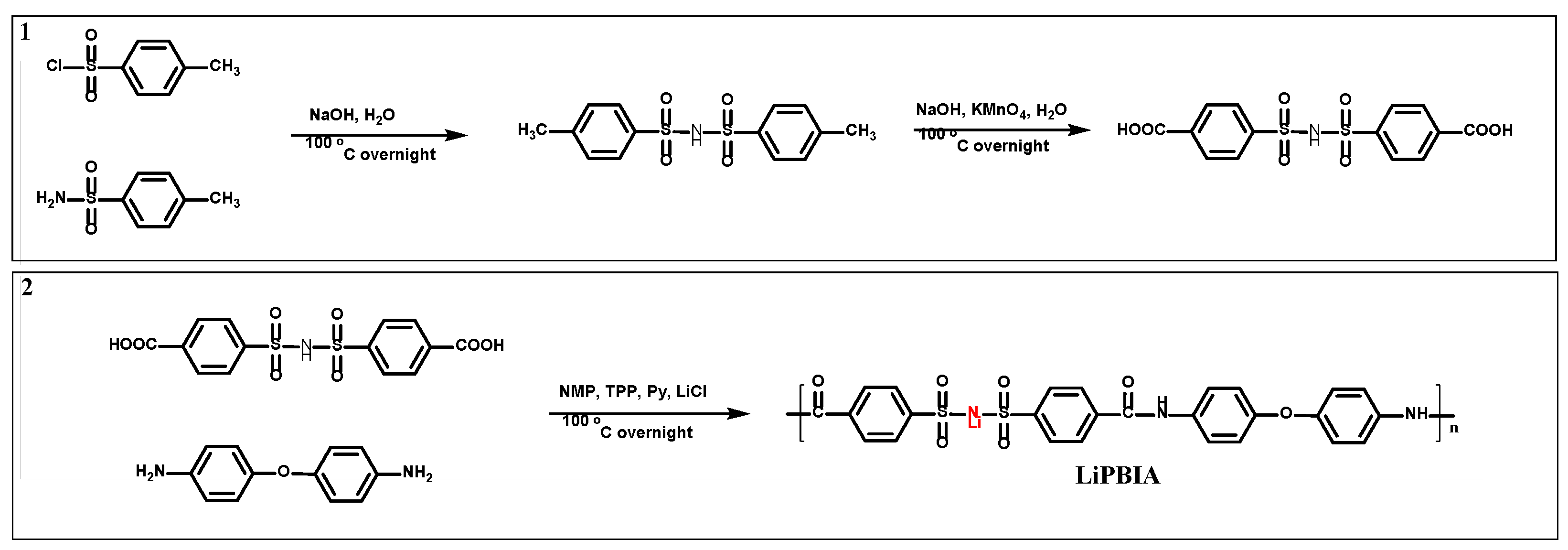
Herein, 4, 4’-dicarboxyl bis(benzene sulfonyl)imide was copolymerized with 4,4’-diaminodiphenyl ether to obtain a single-ion conductor (LiPBIA, as shown in Scheme S1). Relying on solution-casting method, the LiPBIA blended with PVDF was attached to lithium foil surface to form a bis(benzene sulfonyl)imide based SPAL (bi-SPAL). On the one hand, the continuous aggregated Li
+ clusters on fixed bis(benzene sulfonyl)imide anions endow affluent and even Li
+ transport channels, allowing Li
+ deposition process fast and uniform, which can inhibit the growth of lithium dendrite effectively. On the other hand, the bi-SPAL as an interlayer between electrolyte and LMA isolates the contact of the two, impeding the parasitic side reactions between them (
Scheme 1). Employing this bi-SPAL on LMA, the coulombic efficiency (CE) of Li|Cu half cell, interfacial stability of Li|Li symmetrical cell and cycling performance of LFP|Li full cell were detected systemically.
2. Materials and Methods
2.1. Materials
4-methyl benzenesulfonyl chloride (98%), 4-methyl benzenesulfonamide (98%), 4, 4’-diamino diphenyl ether (98%) and potassium permanganate were purchased from Sinopharm Chemical Reagent Co., Ltd without further purification. Anhydrous pyridine (AR, H2O﹤10 ppm), anhydrous dimethyl sulfoxide (AR, H2O﹤10 ppm) and anhydrous N-methyl-2-pyrrolidone (AR, H2O﹤10 ppm) were purchased from Aladdin Co., Ltd. Triphenyl phosphite (TPP) was purchased from Sinopharm Chemical Reagent Co., Ltd and dried with activated 4A molecular sieve for 7 days. Methanol (AR) was purchased from Sinopharm Chemical Reagent Co., Ltd. Poly(vinylidene fluoride) (PVDF, average Mw~400,000) was purchased from Sigma Aldrich Co., Ltd. Carbonate-based electrolyte (1 M LiPF6 in EC/DMC, v:v=1:1) was purchased from DodoChem without any additives. LiFePO4 with encased carbon was purchased from Tianjin STL Energy Technology Co., Ltd. Lithium foil (Φ 16 mm) was purchased from Hefei Kejing Co., Ltd.
2.2. Synthesis of materials
As shown in
Scheme 2, firstly, 300 mL of deionized water was added into a 500 mL two-necked flask, and 0.102 mol of NaOH were slowly added under magnetic stirring. After the NaOH was completely dissolved, 0.10 mol 4-methylbenzene sulfonamide was introduced and the temperature was raised to 95 °C. Finally, 0.05 mol 4-methylbenzene sulfonyl chloride was slowly added within 2 h and the reaction was continued for 12 h at 95 °C. Then, the pH was neutralized to 7, along with much white solid was precipitated. Removed the white precipitate by filtering, and adjusted the filtrate pH to 1, white solid appearing, which is the target product (4, 4-dimethyl bis(benzene sulfonyl)imide, MBSI). Secondly, 0.05 mol of MBSI and 0.05 mol NaOH were added to a 500 mL two-necked flask with 200 mL deionized water. Then, 5 times of KMnO
4 was added in slowly under magnetic stirring for 12 h at 100 °C. After reaction, the by-product MnO
2 was filtered out and the pH of filtrate was adjusted to 1[
26]. After recrystallization processing, the target product 4, 4’-dicarboxyl bis(benzene sulfonyl)imide (CBSI) was obtained. Lastly, 0.01 mol 4,4 '-diaminobenzene diphenyl ether, 0.01 mol CBSI, 20 mL N-methyl-2-pyrrolidone, 15 mL Py and 5.2 mL TPP were added in a 100 mL two-necked flask and reacted at 100 °C for 12 h under the argon flow. Then, the mixture was poured into 100 mL of cold methanol to precipitate the polymer (poly(bis(4-amino benzene) ether-alt-bis(4-carboxyl benzene sulfonyl)imide)amide), and further washed by methanol for several times. The polymer was neutralized by LiOH to obtain the target product of LiPBIA.
2.3. Preparation of electrodes
bi-SPAL@Cu electrode: 75 mg LiPBIA powder and 25 mg PVDF was dissolved in 10 mL anhydrous DMSO to form a transparent solution. The solution was casted on a flat Cu foil (5 cm × 10 cm) followed by removing the solvent through heat treatment. The bi-SPAL coated Cu electrode was punched into small rounds (diameter ~ 16 mm) followed by vacuum drying.
bi-SPAL@Li electrode: 75 mg LiPBIA powder and 25 mg PVDF was dissolved in 10 mL anhydrous DMSO at argon-filled glove box to form a transparent solution. Subsequently, 50 µL of the mixed solution was dropped onto the Li foil (with diameter of 16 mm) and dried at 60 °C for 12 h in an argon-filled glove box.
LFP electrode: 140 mg of LFP powder, 40 mg of acetylene black, 20 mg of PVDF and an appropriate amount of NMP were proportionally placed in a 5 mL beaker followed by stirring for 12 h. Then, the slurry was spread on an Al foil by a doctor blade and removed the NMP by air blowing at 80 °C for 1 h. Finally, the LFP cathode was cut into several rounds (diameter is 12 mm, active material loading is ~1.5 mg cm-2), which were dried at 80 °C under vacuum for 12 h.
2.4. Cell assembly and electrochemical test
The asymmetric Li|Cu half cells were assembled with bare Cu foil or bi-SPAL@Cu foil as the working electrode, bare Li foil as the counter electrode, 1 M LiPF6 dissolved in EC/DMC (v:v = 1:1) solvent as the carbonate-based electrolyte and Celgard 2300 microporous polyolefin film as the separator. The cells were tested on a LAND electrochemical testing system at 25 °C. Specifically, 1 mAh cm-2 of Li is plated on the bare Cu or bi-SPAL@Cu by applying a constant current density of 1 mA cm-2 for 1h and then stripped at the same current density with the opposite polarity until the voltage rised up to 1.0 V. The coulombic efficiency (CE) of each cycle was calculated by dividing the Li stripping capacity with the Li plating capacity and then multiplied by 100%.
The symmetric Li|Li cells were assembled by sandwiching Celgard 2300 microporous polyolefin film between two pieces of the bare Li or bi-SPAL@Li electrode and adding the carbonate-based electrolyte same as the Li|Cu cells. The symmetric cells were cycled at capacity of 0.5 mAh cm-2 with current density of 1mA cm-2 on a LAND electrochemical testing system at 25 °C.
The LFP|Li full cells were assembled similar to the Li|Cu half cells, where the LFP cathode replaced the Cu foil as the working electrode. Before cycling, the electrochemical impedance spectroscopy (EIS) measurements were performed on the VMP3 workstation with a frequency range from 100 kHz to 0.01 Hz with 10 mV fluctuations. The cycle performance were conducted on LAND at 25 °C at 0.2 C and 1 C within the discharge and charge cut-off voltages of 2.5 V and 4.2 V.
2.5. Characterization
The structural of LiPBIA was characterized by NMR spectrometer (AVANCE III HD 400 MHz, Swiss BRUKER), DMSO-d6 as the solvent. Morphology of bare Li and bi-SPAL@Li before and after cycled was captured by scanning electron microscopy (FE-SEM, SU8010, HITACHI). Surficial chemical constitution was detected by X-ray photoelectron spectroscopy on PHI 5000 Versa system (ULVAC-PHI, Kangawa, Japan).
3. Results and discussions
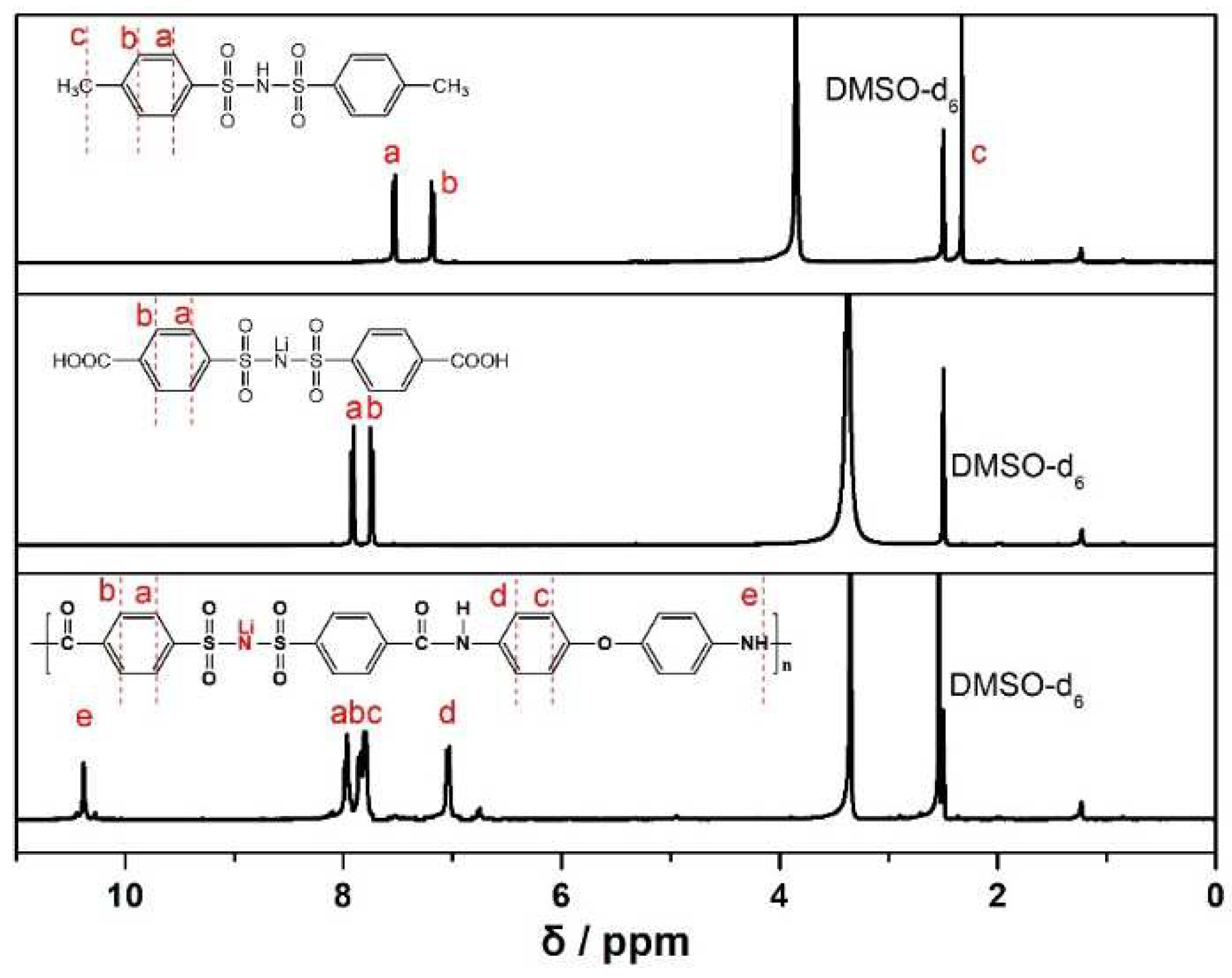
The chemical structure of MBSI, CBSI and LiPBIA was collected by the
1H NMR spectra and as shown in
Figure 1. For MBSI, the two double peaks at 7.54 ~ 7.52 ppm (a) and 7.19 ~ 7.17 (b) ppm were assigned to the adsorption of aromatic protons (a & b), respectively[
27]. A single peak as 2.33 ppm (c) was ascribed to protons of methylene (c). In addition, the ratio of “a”, “b” and “c” peak area closes to 2:2:3, corresponding to the structure of MBSI molecule. For CBSI, the peak of methylene protons of disappeared. At the same time, the two double peaks “a” and peak “b” were shifted to the lower field (7.92~7.90 ppm, 7.75~7.73 ppm), respectively, which should result from that the methyl group was oxidized to carboxyl group. For the LiPBIA, five peaks at 10.38 (e), 7.98-7.96 (a), 7.86-7.84 (b), 7.81-7.79 (c) and 7.05-7.03 (d) were observed, respectively. The hydrogen marked with ‘a’, ‘b’, ‘c’ and ‘d’ could be denoted as ‘benzene hydrogen’, while the hydrogen labeled by ‘e’ was assigned to ‘amide hydrogen’, indicating the target product of LiPBIA was successful synthesized.
After confirming the structural information of LiPBIA, we tested the ionic conductivity of SPAL. It reached up to 0.96 mS cm
-2 when soaked with liquid electrolyte (
Figure S1). Such a high value is almost comparable to1.12 mS cm
-2 of commercial liquid electrolyte, which should be attributed to the large amount of lithiated bis(benzene sulfonyl)imide anions, providing more sites for Li
+ dissociation and transportation[
28]. Subsequently, a mixture of LiPBIA and PVDF (3:1) was employed to fabricate SPAL on the surface of LMA (denoted as
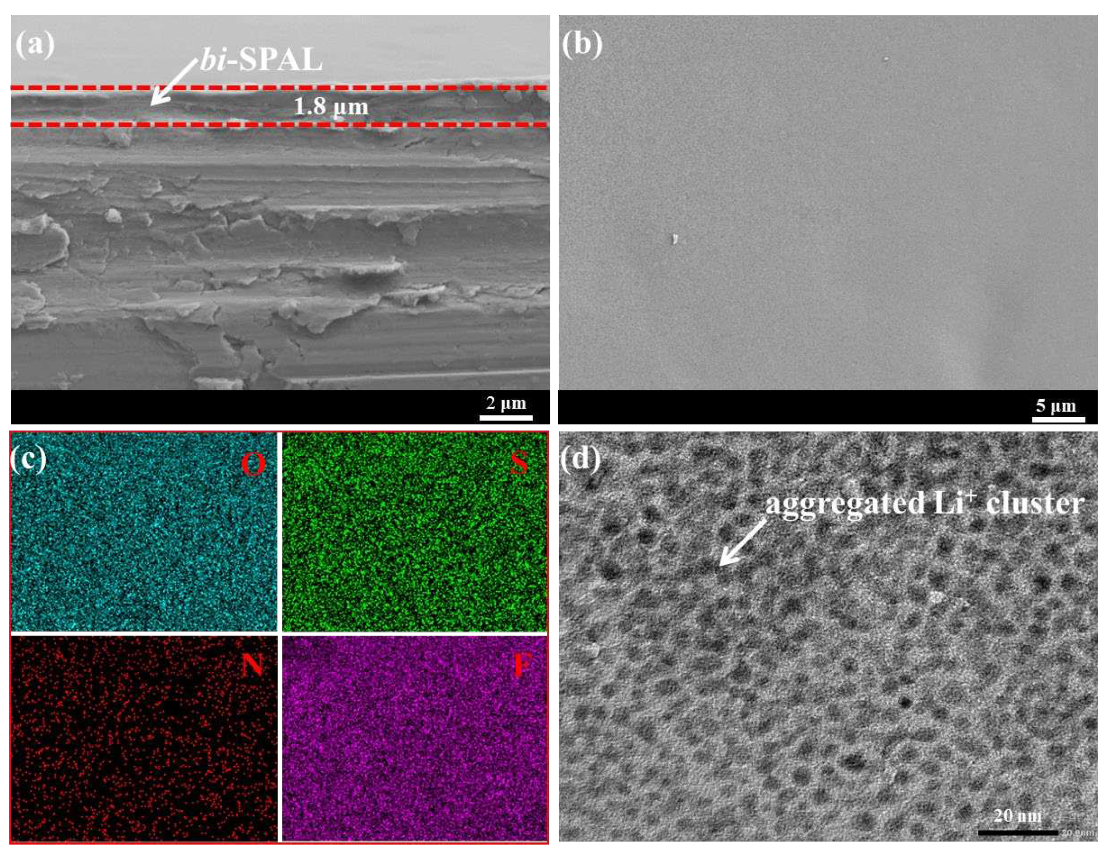
bi-SPAL@Li). With the assistance of SEM, we observed that the SPAL was fitted on the surface of LMA evenly and compactly as shown in
Figure 2a. Between SPAL and LMA, there was no crevice, while the thickness of the SPAL is approximately 1.8 μm. Such a compact SPAL with a certain thickness appressed on LMA can avoid the direct contact between LMA and electrolyte effectively.
Figure 2b displayed the surface section of SPAL@Li electrode, which demonstrated that the surface is smooth and close. Mapping images (
Figure 2c) illustrate that the distribution of O, S, N, F elements on SIPE@Li electrode is homogeneous, further suggesting that the SPAL is covered on the LMA continuously and densely. As zoomed in by high-resolution transmission electron microscopy (HRTEM), the typical microphase separation structure of SPAL is blindingly obvious and tightly aggregated clusters are uniform dispersed (
Figure 2d), which formulates efficient Li
+ transport channel, ensuring Li
+ transport fast and homogeneous [
29].
The CE of Cu electrode was compared with
bi-SPAL@Cu electrode to investigate the influence of
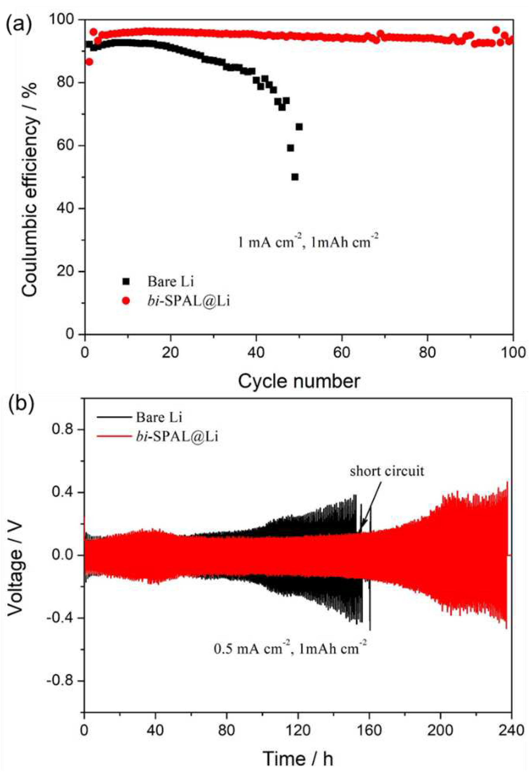
bi-SPAL to reversible Li plating/stripping performance. In the 1
st cycle, the CE of
bi-SPAL@Cu electrode (~ 86.5%) is relatively lower than 92.1% of the bare Cu electrode (
Figure 3a), which should be attributed to the larger Li nucleation overpotential (223 mV vs. 79 mV, Figure. S2a) caused by the initial unstable interface between Cu electrode and
bi-SPAL. Experienced one cycle, the Cu |
bi-SPAL interface was stabilized. The CE of
bi-SPAL@Cu electrode increases to 96.1% rapidly at the 3
th cycle, which could still remained 93.9% after 100 cycles. With regard to bare Cu electrode, the CE in the 3
th cycle was barely attenuated, which dropped down to 78.1% vertiginously after 40 cycles. Meanwhile, the Li stripping/plating overpotential for
bi-SPAL@Li is about 97 mV at the 3th cycle, which could maintain for 100 cycles continuously, superior to the bare Cu electrode (
Figure S2b ~ d). Furthermore, Li|Li symmetric cells were assembled to evaluate the interfacial stability of LMA/electrolyte. As the black line in
Figure 3b, the overpotential of the bare Li symmetrical cell increased rapidly after 90 h. This illustrated that bare Li anode only could work effectively in a limited short time (< 90 h), which should be owing to the complicated side reactions between LMA and liquid electrolyte[
30]. Side reactions consumed portion of Li metal leading to an inferior performance, meanwhile, a more complex surface appeared, which would affect the Li
+ transfer efficiency, and the generation of lithium dendrite would exacerbate. As progressed to 152 h, short circuit took place, which could be attributed to unmanageable lithium dendrite formation, connecting the positive and negative electrodes together. When coating with
bi-SPAL, the symmetrical Li|Li cell using
bi-SPAL@Li electrode displayed a much more stable Li plating/stripping behavior for 180 h and cut off at 240 h. More importantly, the polarization potential of
bi-SPAL@Li symmetric cell is similar to the bare one, which may attribute to the appreciable ionic conductivity of
bi-SPAL. These results indicate that the as-prepared
bi-SPAL is indeed critical for facilitating fast Li
+ transport and reversible Li plating/stripping[
31].
Ultimately, the LFP|Li full cell was assembled and tested to further explore the practical application of
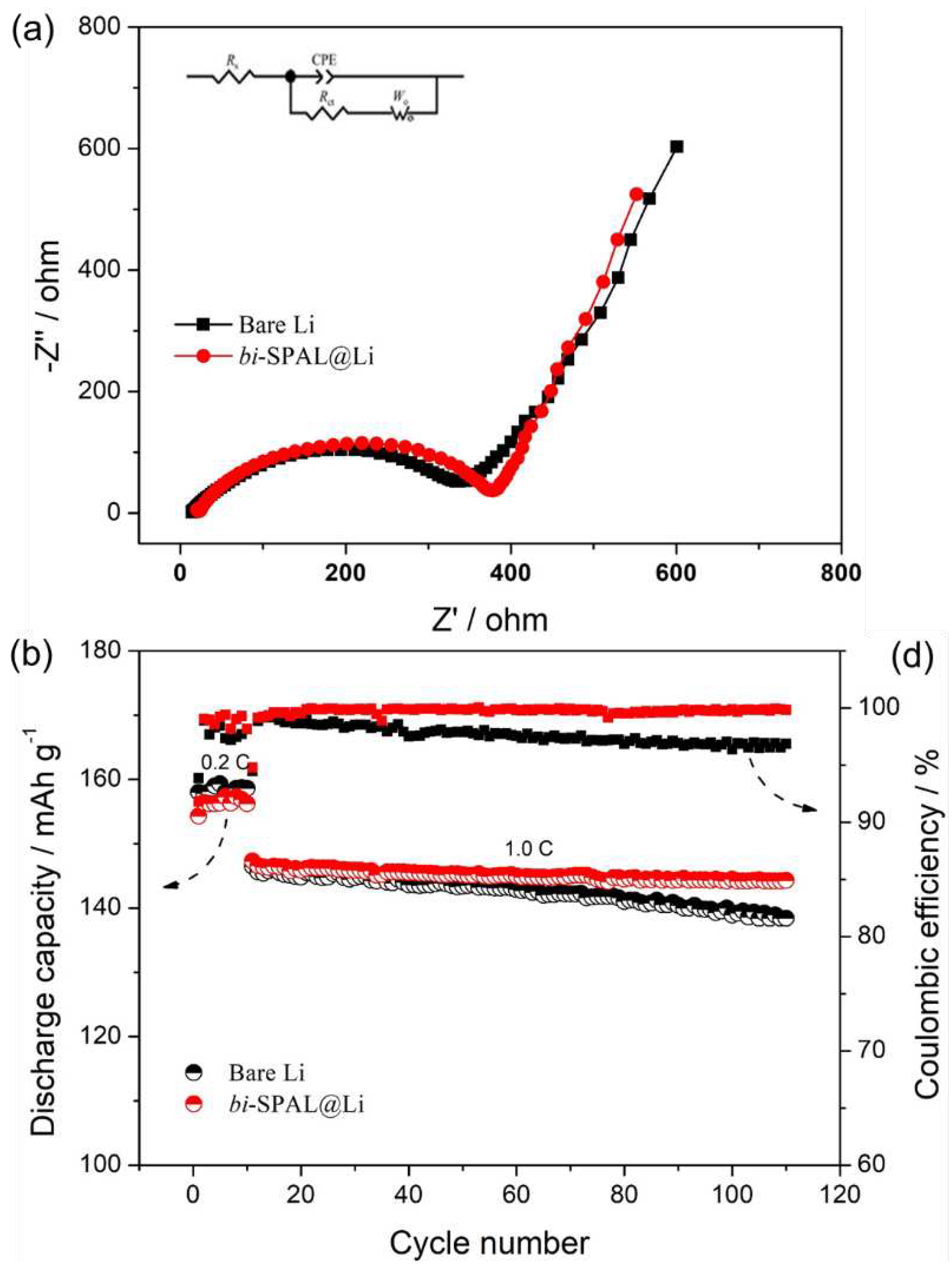
bi-SPAL@Li electrode, bare Li as comparison. Before cycling test, the electrochemical impedance spectroscopy (EIS) was measured and the EIS results with the equivalent circuit are shown in Figure. 4a. Clearly, the
Rs (ohmic resistance) and
Rct (resistance of charge transfer reaction between the electrolyte and the electrode) of full cell fabricated with the
bi-SPAL@Li electrode was 19.3 Ω and 360.1 Ω,respectively, which is relatively higher than that of the bare Li electrode (13.6 Ω, 329.7 Ω). This should be ascribed to the slightly lower ionic conductivity of
bi-SPAL compared to the liquid electrolyte (
Figure S1), resulting in the increase of both
Rs and
Rct. Therefore, the discharge capacity of the full cell with
bi-SPAL@Li as anode is about 156.3 mAh g
-1 at 0.2 C, slightly lower to 158.2 mAh g
-1 of bare Li anode (
Figure 4d). Intriguingly, when the charge/discharge rate increased to 1 C, the discharge capacity of the two cells was almost equal (146 mAh g-1). After 100 cycles, the cell with bi-SPAL@Li anode still delivered a discharge capacity of 144.5 mAh g-1 with CE as high as 99.84 %, which was superior to the value of 138.4 mAh g-1 and 96.87 % upon the bare Li. These results confirm that the bi-SPAL is beneficial for the cyclic stability of lithium metal battery.
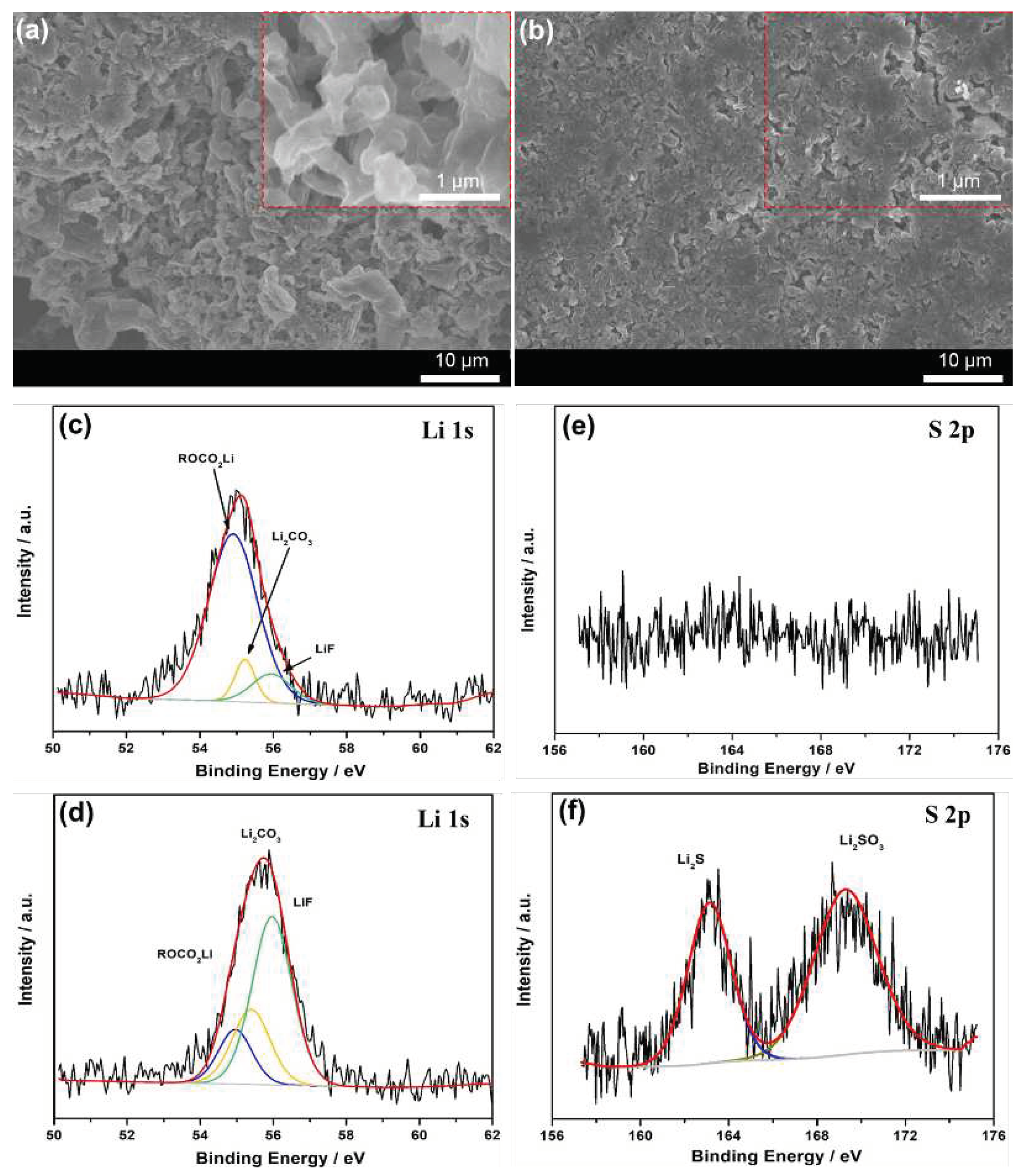
The SEM analysis was utilized to explore the surficial morphology and elemental state of bi-SPAL after 100 cycles. As shown in
Figure 5a, the surface of bare LMA turns to rather porous and numerous isolated dendritic particles, while the LMA protected by bi-SPAL does not change significantly (
Figure 5b). The composition varieties of the cycled LMAs were further revealed by Li 1s and S 2p XPS analysis. For bare LMA (
Figure 5c&e), the Li 1s XPS spectra could be fitted to the peaks of ROCO
2Li (54.8 eV), Li
2CO
3 (55.3 eV), LiF (55.9 eV) and no S 2p peaks were observed. For bi-SPAL@Li (
Figure 5d&f), in addition to the peaks of Li 1s, the peaks of S 2p also appeared, which could be fitted to Li
2S (163.2 eV), LiSO
3 (169.4 eV), respectively. The stronger deconvoluted peak of LiF and unique peaks of S 2p could be attribute to the reduction of PVDF and LiPBIA with LMA, respectively, which is beneficial to form a uniform and robust SEI layer[
30]. Thus, the parasitic reactions between LMA and liquid electrolyte and the Li dendrite growth can be inhibited.
