1. Introduction
In the last decades, the economy centred on the general reduction of energy consumption and CO
2 emissions has dictated important changes in every sector, especially in the construction world. Buildings are, in fact, key consumers of energy in Europe, and a rising tendency in energy use has been globally recorded in the last twenty years [
1]. According to the European Environment Agency (EEA), in 2017 the transport sector accounted for 31% of total final energy consumption in the European Member States, followed by households (27%), industry (25%) and services (15%) sectors [
2].
The energy use in households is mainly related to space and water heating, which together are responsible for 80% of the total building energy consumption [
3]. The high percentage is mostly due to poorly insulated envelopes and less-efficient heating equipment, mainly fossil fuel-based and traditionally present in existing buildings.
Similar trends are also estimated for greenhouse gas emissions. Buildings and construction together account for 39% of energy-related CO
2 emissions when upstream power generation is included [
4]. Considering the high potential for cost-effective energy savings, the building sector has become a priority area for the European Commission, which has sponsored various actions to reduce the building requirement and promote their renovation. Prominent examples of this effort are the Directive 2002/91/EC [
5] and the Directive 2010/31/EU [
6], commonly known as the EPBD (from its full name Energy Performance of Buildings Directive) and its recasting. The first is mainly centred on defining a standardised methodology more oriented to new buildings. The second, instead, aims to deal with existing buildings not only when they are subjected to a significant renovation but also in replacing and retrofitting a few elements or technical systems. After the EBPDs, the European Member States have shown a growing interest in building energy improvement, and, as a main result, a specific article centred on building renovation was introduced in the new Energy Efficiency Directive 2012/27/EU [
7].
The great attention to the existing building stock is due to the consciousness that the European heritage was mainly erected before the 1960s when the sustainability problem was in a preliminary phase, and energy building regulations were minimal. According to the Building Performance Institute Europe (BPIE) survey, in fact, 35%–42% of the building is dated before the 1960s, and another consistent part was erected between 1961 and 1990 for the effect of the massive boom in the construction sector [
8]. The statistics underline the need for energy-efficient retrofit solutions, essential under present and, in particular, future conditions, considering that the construction age of a building is among the main features that affect its climate change vulnerability. Various innovations for improving the energy performance of buildings and, generally, cities thus reducing their environmental impact involve smart and intelligent devices, mostly renewable-based, inserted directly on building surfaces [
9,
10] or at an urban scale [
11,
12,
13].
In this way, the present research aims to evaluate the climate change vulnerability of an existing building located in central Italy, estimating its energy needs and comfort rates under future meteorological conditions. The case study is analysed through dynamic simulations performed in EnergyPlus (Version 8.9) with its DesignBuilder interface (Version 6.1.3), considering both the current and energy-improved versions.
The paper is structured as follows: after this brief introduction, considerations about Double Skin Façades and their use in new and retrofitted buildings are reported in
Section 2.
Section 3 describes the case study, the main energy modelling features and the calibration phase carried out for testing the model capability in predicting the real energy behaviour of the reference building.
Section 4 focuses on the presentation of the methodology adopted for generating future climatic files and shows the obtained results expressed in energy consumption and comfort rates. Finally,
Section 5 draws the main conclusions.
2. Double Skin Façades for New and Retrofitted Buildings
The Double Skin Façade (DSF) is a European architectural trend mainly driven by the aesthetic desire for all glass façade buildings, the need for a consistent reduction in energy consumption, and the parallel increase of the indoor comfort conditions, both acoustic and thermic [
14]. Described as a pair of glass skins separated by an air corridor ranging in width from 0.20 m to several meters by Uuttu [
15], the DSF concept appeared in the early 20th century in the northern European countries. In the preliminary version, the multi-layered façade was conceived and designed for reducing heating consumption thanks to the air buffer enclosed in the cavity, which acts as a barrier for heat losses and as a filter for the exchanges through the external envelope. The extreme variety of the possible DSF typologies can be classified according to different criteria
, independent of one another and based on the geometric characteristics of the façade and its operation mode [
16]. The criteria mentioned above are:
The ventilation mode (Natural, Mechanical and Hybrid ventilation).
The compartmentalisation of the façade (Multi-Storey, Shaft-Box, Corridor and Box-Window DSF).
The airflow type (Exhaust Air, Supply Air, Static Air Buffer, External Air Curtain, Internal Air Curtain.
Based on the analysis conducted on 200 buildings all over the world [
17], the Multi-Storey DSF is the most popular configuration, followed by the Box-Window and Corridor types. Moreover, naturally ventilated DSFs are preferred, and the outdoor air curtain airflow path is the most widespread.
Preliminary and simple DSF examples appeared in the first decades of the 20th century, following the influence of the new architectural tendencies based on the use of steel and glass, spread worldwide after the Great Exhibition of Chicago. Only in the early 70s, when the concept was exported to North America, the multi-layer façade became largely sponsored as the best example of possible energy efficiency solutions. New configurations and advanced materials capable of improving the building energy performance started to be evaluated combined with DSFs, and, since the second decade of the 21st century, the exploration of new shapes became an essential and universal aspect among engineers and architects, causing the introduction of more articulate and sophisticated systems. Besides, the popularity of multi-layer configurations, a great concern is related to the simulation approach adopted for investigating their thermal behaviour which should be appropriately selected. Various works underline the limits and difficulties of energy analyses in predicting the temperatures and airflow rates inside DSF channels, suggesting new methods which combine them with Computational Fluid Dynamics (CFD) modelling [
18,
19,
20].
Nowadays, the analysis of solutions for improving the energy behaviour of Double Skin Façade is a topic quite explored by researchers all over the world. Detailed investigations are conducted for evaluating the DSF efficiency associated with different glazing options and shading systems. According to the literature review [
21], using single clear glass for the inner pane and double reflective glazing for the outer surface guarantees the best option with annual cooling savings of up to 26% compared to a traditional external wall and single absorptive window glazing. Another essential and widely analysed aspect involves the shading system and evaluates the main parameters responsible for better solar protection. According to Gratia et al. [
22], in fact, building cooling consumption can decrease up to 23% by paying attention to three main aspects which are the location of the blinds, the colour of the blinds and the opening of the Double Skin. Other investigations involve possible connections of DSF to the Heating, Ventilation and Air Conditioning (HVAC) system, its use as a solar chimney or the insertion of new elements like Photovoltaic (PV) cells, vegetation, or Phase Changing Materials (PCMs) [
23,
24,
25,
26,
27,
28,
29,
30,
31,
32,
33].
The DSF innovation does not involve only energy efficiency aspects. A novel focus consists of the insertion of structural elements able to confer an extra function, the seismic one, to the so-called Engineered Double Skin Façade [
34,
35,
36,
37,
38,
39]. A such conceived façade becomes a mass damper system or an exoskeleton which, in case of restoration, can reduce the seismic vulnerability of existing buildings.
On the base of the considerations mentioned above, multi-layer façades represent interesting options for both new and retrofitted buildings. In fact, several works study the improvements achievable by inserting DSF systems on the existing heritage, underling their key role in cutting building energy consumptions and CO
2 emissions if properly designed and oriented [
40,
41,
42,
43,
44].
3. The Case Study
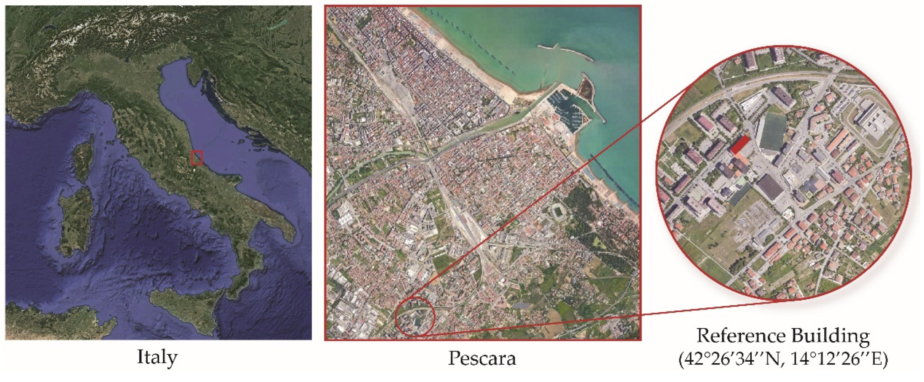
The reference building is located in a residential suburb of Pescara, Central Italy, and belongs to the social housing stock (see
Figure 1). Selected for being representative of an existing heritage without architectural quality but mostly present on the territory, it reflects the typical construction practice of the past without any attention to energy problems. The area is known for its Mediterranean climate, with mild winters and hot, sunny summers. According to the climate classification system developed by Köppen-Geiger [
45], the city has a humid subtropical climate denominated Cfa. The C group corresponds to “Warm Temperate” climates, the small letter f means “fully humid” and indicates the lack of a dry season, whereas the letter a corresponds to a “hot summer”.
The case study is a seven-storey reinforced concrete building characterised by a rectangular shape with 60.00 m and 12.00 m as main dimensions. The inter-storey height is 2.70 m, except for the ground floor, which is higher than the others (3.50 m). The garages and the entrance are on the ground floor, while residential apartments are on the upper levels. The building envelope does not comply with the current standard in the sector. The perimeter walls (0.33 m depth), in fact, do not present any insulation materials but only an air gap enclosed by two brickwork layers, with a total transmittance value (U) equal to 1.46 W/m
2K. There are also 0.23 m thick walls placed for delimiting the apartment from the staircase, and partitions (with 11 cm depth) to subdivide each apartment into various thermal zones. Moreover, single glass windows with 3.78 W/m
2K transmittance contribute to the building’s inadequate performance, especially during the coldest months.
Table 1 summarises the thermal properties of the building envelope.
The building heating involves the use of radiators with a seasonal Coefficient of Performance (COP) equal to 0.84 and natural gas as the source. Splits are installed for cooling the inner spaces and improving the inhabitants’ comfort condition. The cooling COP is set equal to 1.40, and the source is electricity.
The temperature setpoints for heating and cooling are, respectively, 22°C (with 20°C as the set-back temperature) and 28°C in all thermal zones. The metabolic factor is set to 0.90 for the whole building, as well as for the clothing insulations, which is 0.50 clo for the summer season and 1.00 for the winter period. The model infiltration is considered constant and fixed at 0.70 ac/h.
Table 2 depicts the input parameters which vary according to the activity of the thermal zone.
The influence of neighbouring buildings is taken into account by inserting, as block components, the closest structures which could shade the case study and, for the same reason, the presence of the balconies on the northwest façade is considered placing external profiles.
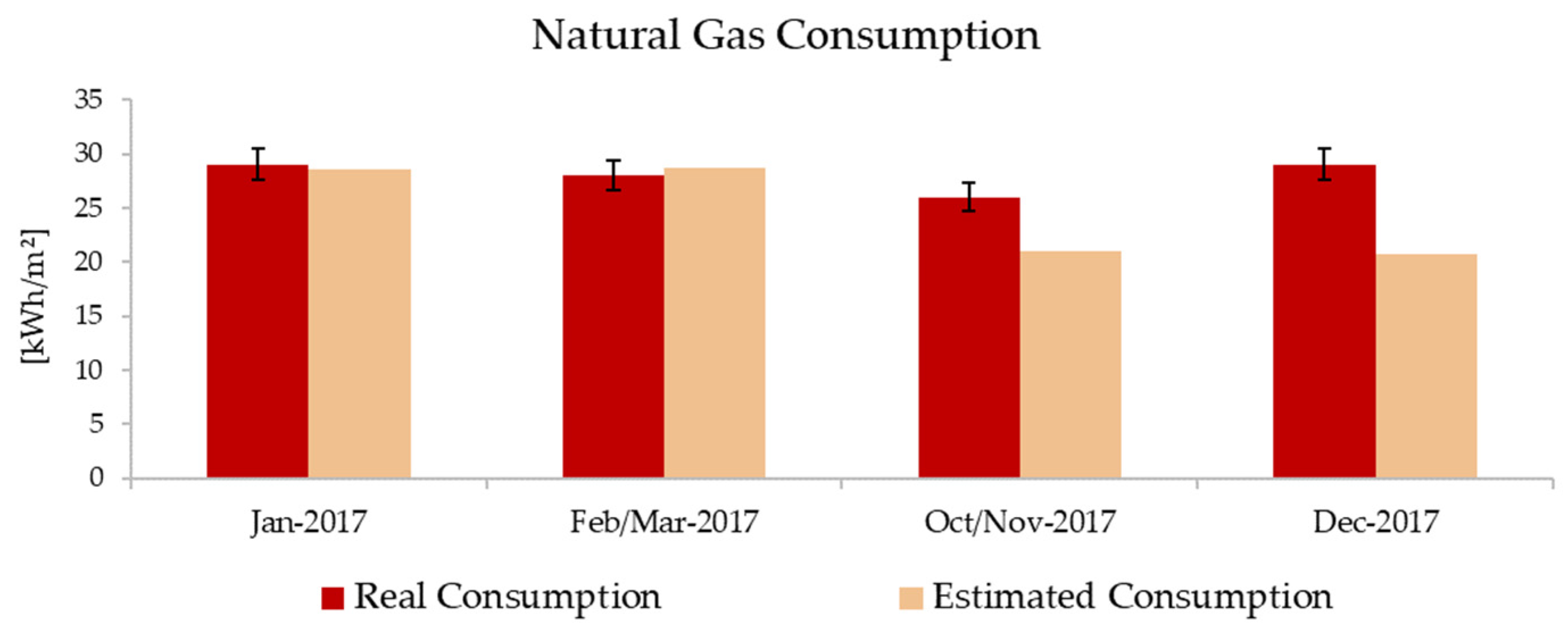
Once the case study has been modelled, preliminary dynamic energy simulations were carried on for estimating the building’s natural gas consumption to be compared with data from building bills. The collected bills are referred to 2017, and the heating period (October 1st-March 31st) is considered for calibration. Thus, monthly simulations were performed setting the natural gas consumption (heating + cooking) as a key output, expressed in kWh/m
2. Following the recorded data, the consumption was defined in a two-month range, except for January and December. The analyses were simulated using measured weather data collected by Climate Network, a private and professional network of urban meteorological stations that records hourly values for all climatic parameters [
46]. Error bars, set at 5%, were inserted as inferior and superior limits for the comparisons.
Figure 2 shows the general accordance between estimated and measured values. The model, in fact, can predict within the acceptable range the energy consumption for January and February/March bimesters. More significant differences are calculated for December for which the estimated values are out of the range. Such behaviour can be explained by considering that the available bill is referred to December 2017-January 2018 and the expected consumption for a single month is done by dividing the total amount by two. For this reason, the December data were not strictly taken into account for the calibration. The same inaccuracy can also be seen for the October-November bimester but, in this case, the principal reason stands in the limitations of predictions for transitory months because deeply influenced by the inhabitants’ comfort condition and their use of occupied spaces. In fact, as underlined by various works previously carried on in energy simulations, the building requirement/consumption for mild periods could vary more than the rest of the year, according to human behaviour (inhabitants’ age, habits, etc.). Based on the comparisons, the model can be considered calibrated and able to describe the real energy behaviour of the case study.
3.1. DSF Energy Modelling
A 1.00 m cavity depth Double Skin Façade is placed on the north and south building elevations and external blinds with low reflectivity slots are inserted and designed for being operable only during the hottest months thus avoiding the overheating risk of the inner spaces. The DSF is conceived for being naturally ventilated. External and internal grills are located, respectively, on the outer skin and the inner layer, represented by the existing building envelope. External grills are active, allowing the air to enter the Double Façade, during the hottest months, whereas they are closed for the winter period, creating a buffer area. Internal grills, instead, are designed for being adjusted by users, according to the inner temperature distribution. The natural ventilation of the building is controlled by inserting the outdoor maximum temperature check. This set avoids the overheated air inside the cavity entering the building with adverse effects on the cooling side. The outer skin of the DSF is made of a steel structure and high-performance windows (triple glass) with low U value and solar heat gain coefficient, respectively, equal to 0.78 W/m2K and 0.47.
The energy modelling of the DSF is done by setting the cavity as an unoccupied zone with no HVAC or lighting template data. Moreover, the internal convection mechanism is activated to model the cavity air space correctly, and a complete interior and exterior solar distribution algorithm is switched on, allowing solar radiation to be accurately transmitted through the interior glazing in the partition.
Various configurations are modelled and tested to evaluate the effectiveness of DSF systems. Multi-Storey, Shaft-Box, Corridor and Box-Window DSFs are investigated in terms of energy consumption and thermal comfort conditions. Two different cases are studied for the Corridor type: the outer grills are inserted on the principal elevation of the façade in one case and on the lateral envelope in the other. The inner partitions, eventually inserted inside the cavity according to the selected category, present single-glazed windows enclosed in the steel structure.
Figure 3 schematises the chosen options, identifying the air fluxes which enter/exit each DSF typology.
4. Dynamic Energy Simulations under Future Climate Conditions
4.1. Generation of Future Climatic Files for Dynamic Energy Simulations
Future climatic files are generated by using the Coordinated Regional Climate Downscaling Experiment (CORDEX). Sponsored by the World Climate Research Program (WCRP) to develop a coordinated framework for evaluating and improving Regional Climate Downscaling (RCD) techniques, CORDEX produces worldwide fine-scale climate [
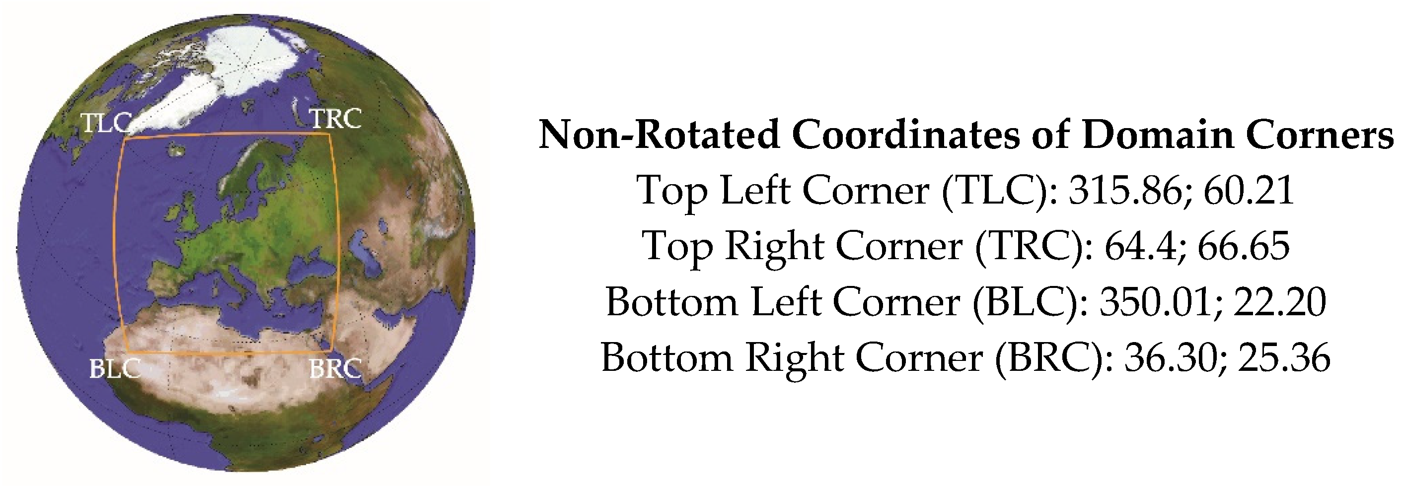
47]. The CORDEX results are assumed as a baseline by the Intergovernmental Panel on Climate Change (IPCC) for defining climate change impact and adaptation studies. Its various domains allow the estimation of climatic variables all over the world, and the Euro-CORDEX, reported in
Figure 4, is its European branch.
The Aire Limitée Adaptation dynamique Développement InterNational (ALADIN) is a limited area bi-spectral model developed at the beginning of the 1990s within a large consortium gathering numerous weather centres in Europe [
48]. The main peculiarity is that, contrary to most of the available RCMs which are “grid-point” models, it has been designed as a spectral model with the exception that all physical parameterisation computations are performed in the conventional grid-point space. This approach also requires the employment of effective direct and inverse spectral transformations between spectral and grid-point spaces [
49]. Since the beginning of the 2000s, the ALADIN model has been used at the Centre National de Recherches Météorologiques (CNRM) with the name CNRM-ALADIN. Various works, centred on the evaluation of the accuracy and effectiveness of this model over differently sized domains, underline the good capability in the estimation of climatic parameters on both spatial and temporal scales inside the European area [
49,
50,
51].
The CNRM-ALDIN, available in Euro-CORDEX, is selected for elaborating future climatic files to be adopted as inputs in dynamic simulations. Data with a 3hs-time frequency are extracted from the nearest grid point to Pescara, which is 7.50 km far from the case study, placed at 42°28′57′’ northern latitude and 14°08’07′’ eastern longitude. The selected RCP is 4.5, which is consistent with a future with relatively ambitious emission reductions, and this scenario is chosen for being in accordance with national policies in the reduction of greenhouse gas emissions.
The available weather variables are relative humidity, atmospheric pressure, global solar radiation, wind velocity and temperature. The definition of the reference year is conducted according to the method described in the technical standard EN ISO 15927-4:2005 and following its suggestions [
47,
52]. Multiple years are extracted for obtaining various typical years.
The first step involves the calculation of the daily averaged value for each climatic parameter (p), month (mt) and year (y) of the datasets. Then, the averaged values for a specific month of all the available years are sorted in increasing order to calculate the cumulative function ϕ
(p, mt, i) for each parameter and i
th day using Equation 1.
where k
(i) is the rank order of the i
th day and N is the total number of days for a month over all years.
The following step consists in sorting the averaged values for a specific month and year in increasing order for obtaining the cumulative distribution function F(p,y, mt, i) for each parameter and i
th day (Equation 2).
Then, for each month and year, the statistics by Finkelstein-Schafer are defined according to Equation 3. The last two steps involve the sorting of months, for which the rank is calculated for every parameter and summed for obtaining the total ranking and for each month, among the first three months with the lowest ranking sum, the one with the lower absolute deviation is chosen as representative for the TMY generation.
For improving the quality of the generated TMY, weighting meteorological parameters are inserted in the Finkelstein–Schafer, as suggested by Cebecauer et al. [
52]. The stronger influence of some variables than others is taken into account by increasing the weight of those parameters. Higher impact factors are attributed to surface temperature and solar radiation (8/24), whereas a lower value (4/24) is assigned to relative humidity and wind speed that slightly affect energy simulations. A twenty-year range is selected for generating the typical year. Thus, data from 2020 to 2040, 2040 to 2060 and 2060 to 2080 are used for elaborating, respectively, 2030, 2050 and 2070 TMYs. Once the selected years were generated, a cubic spline function is used to obtain interpolated values and transform the time frequency of the investigated parameters from 3hs to 1hr.
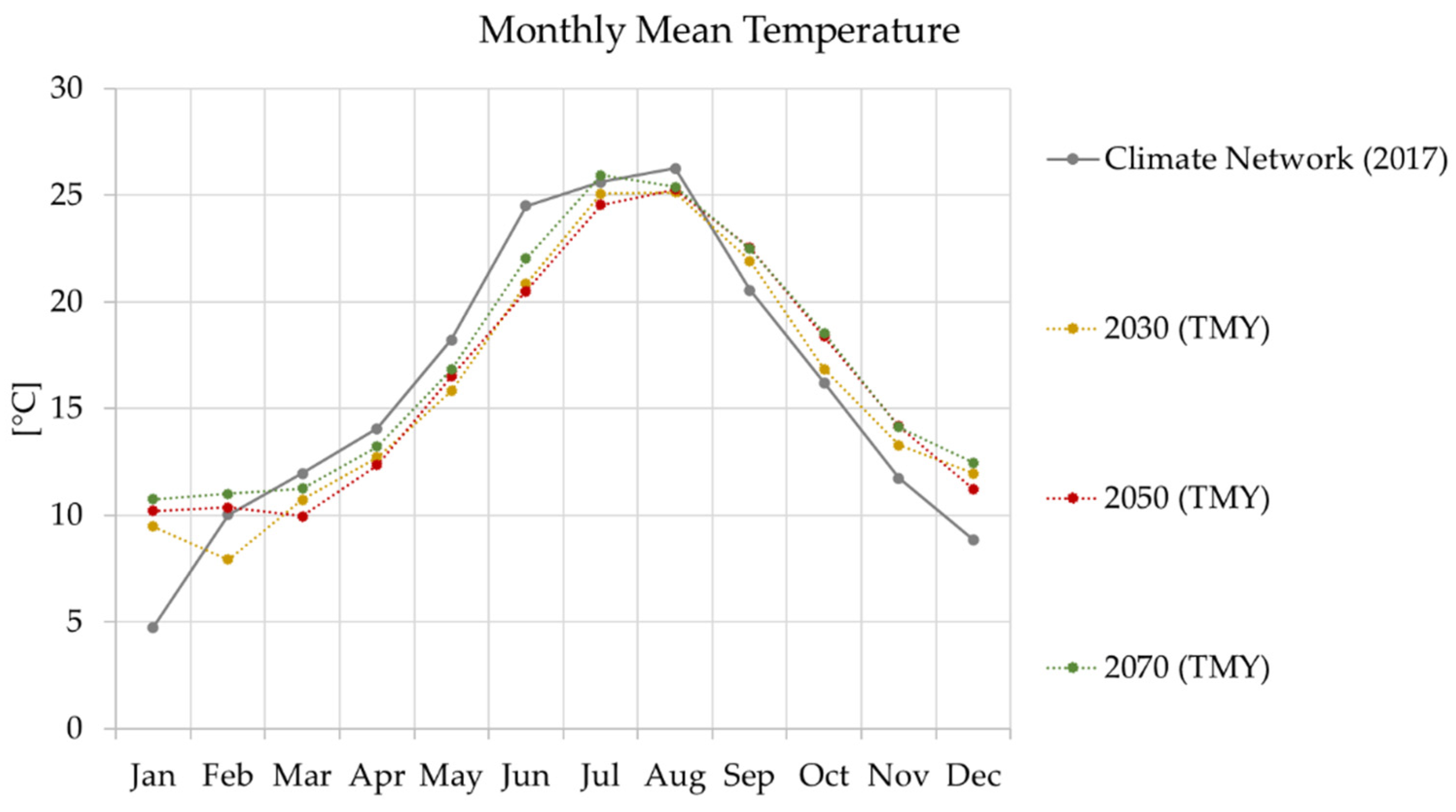
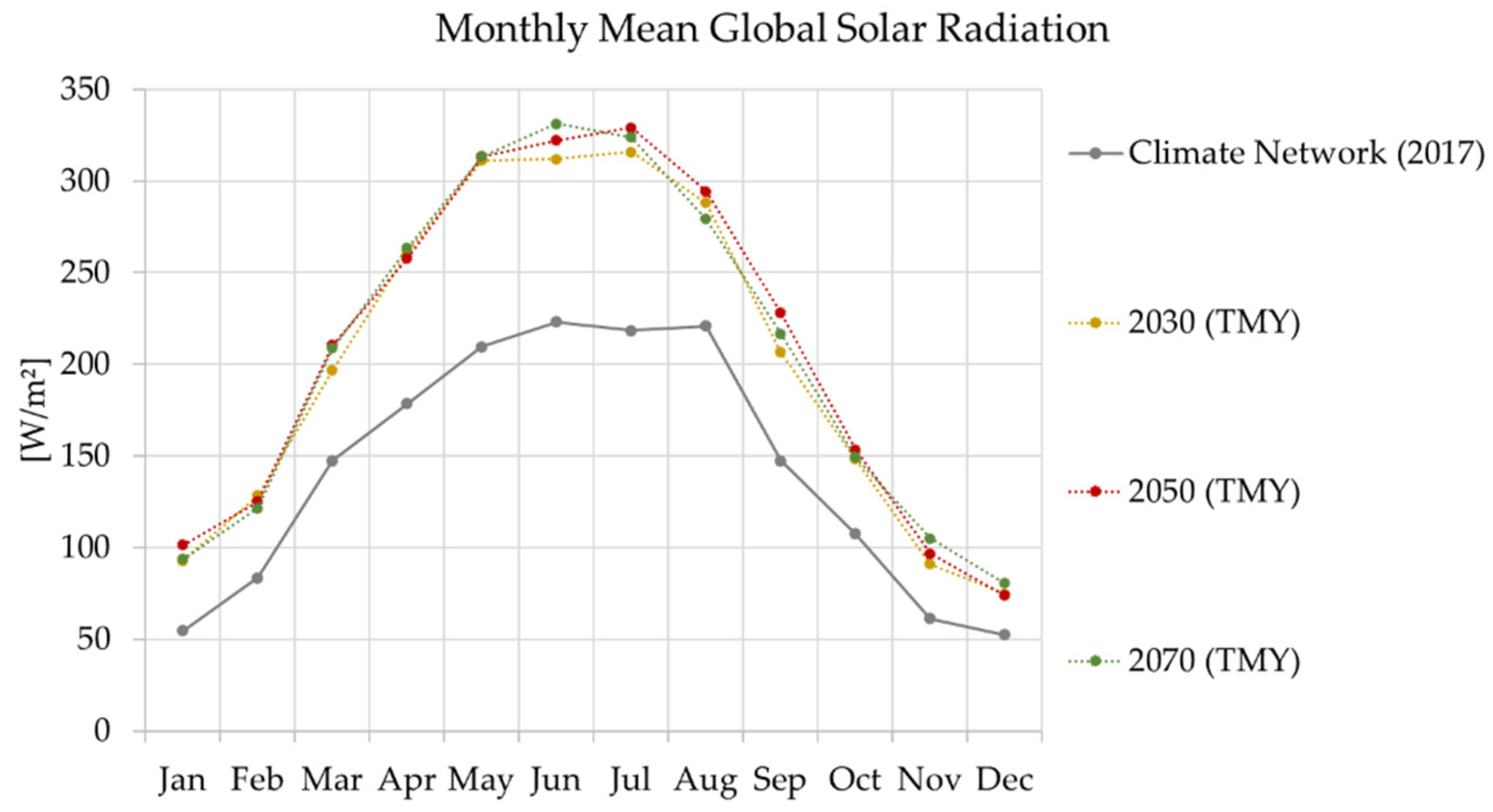
Figure 5 and
Figure 6 depict comparisons of monthly mean values for temperature and global solar radiation between actual (Climate Network database) and future (2030, 2050 and 2070 TMYs) data. The future conditions (dotted lines) tend, in general, to assume similar values and trends of those referred to the year 2017. According to the predictions, higher temperatures are attended for the coldest months (from November to February), while a little reduction is estimated for summer. More profound variations are expected, instead, for global solar radiation. In this case, the picks estimated by CORDEX TMYs are much higher than those recorded in the present, reaching up to 330 W/m
2.
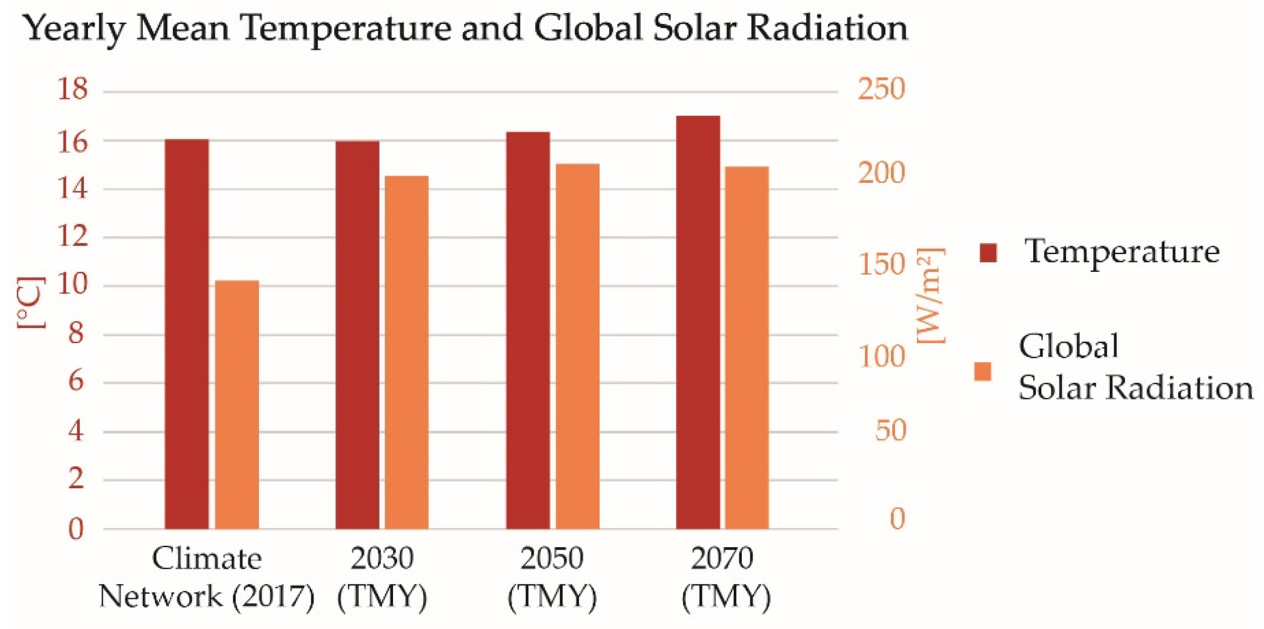
Comparing these parameters to early averaged values (
Figure 7), the same trend is confirmed. On the temperature side, from actual to future conditions, the increment is gradual, reaching a 2°C delta between 2017 and 2070, whereas a higher variation is expected for solar radiation. It is essential to underline that these comparisons involve projections related to a specific scenario which considers the adaptation of policies for CO
2 emission containment.
4.2. Building Energy Modelling under Future Climate Conditions
The impact of climate change is analysed, evaluating the effect that future outdoor conditions could have on the reference building in its existing and improved version. The case study’s energy performance is assessed in terms of energy consumption and thermal comfort rates. In the first case, the results are referred to the annual building heating and cooling use, whereas the thermal comfort is investigated considering a weekly timestep, simulating alternatively the typical summer (August, from 17th to 23rd) and winter (January, from 20th to 26th) conditions. Moreover, for defining comfort/discomfort rates, the operative temperature is estimated for two different building thermal zones, selected for their orientation. North and south exposed thermal zones are chosen for investigating, respectively, the winter and summer thermal comfort. This choice is made considering the building dimensions and for avoiding averaged values that could not represent the real energy behaviour.
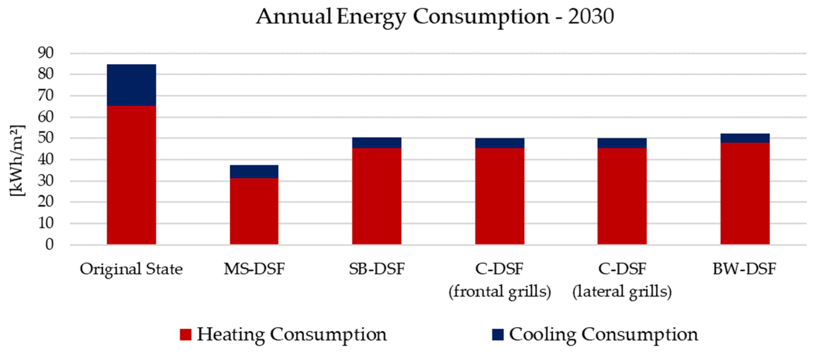
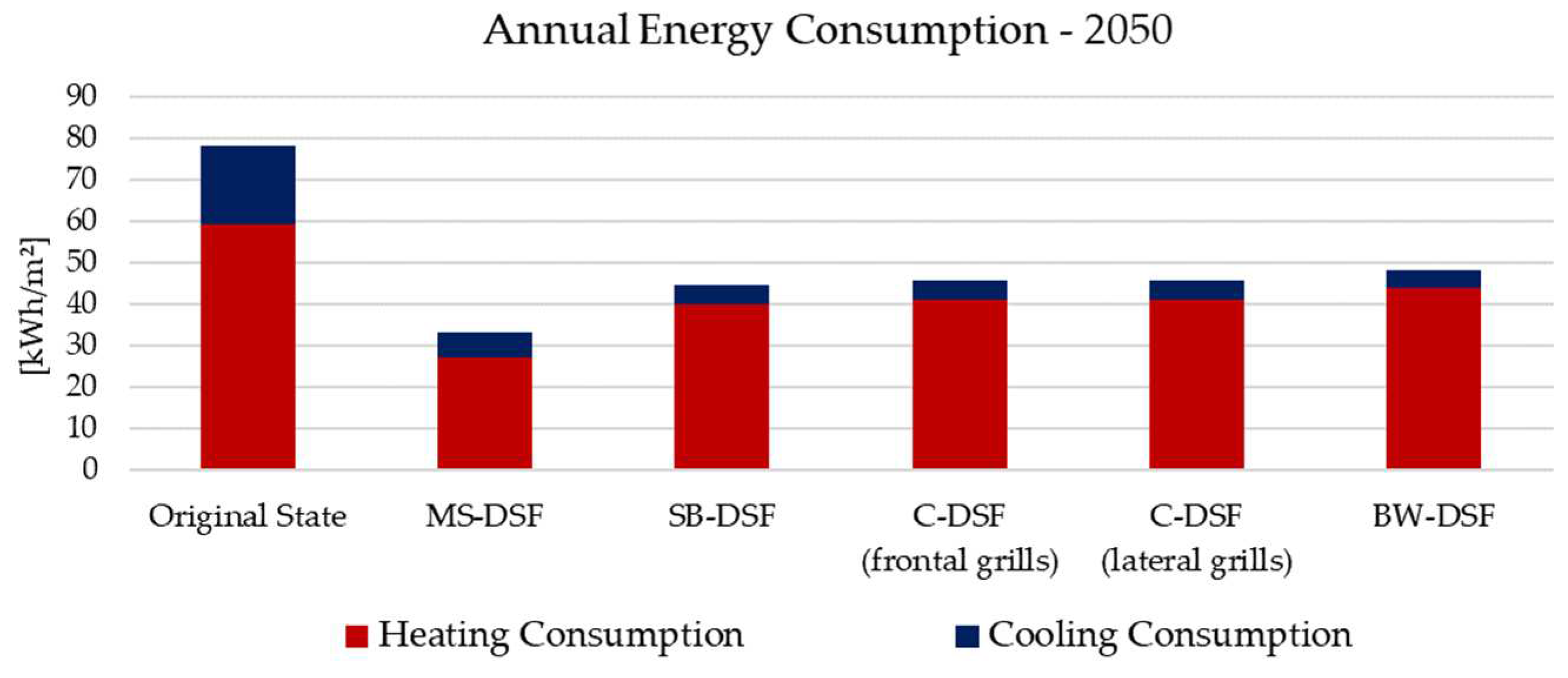
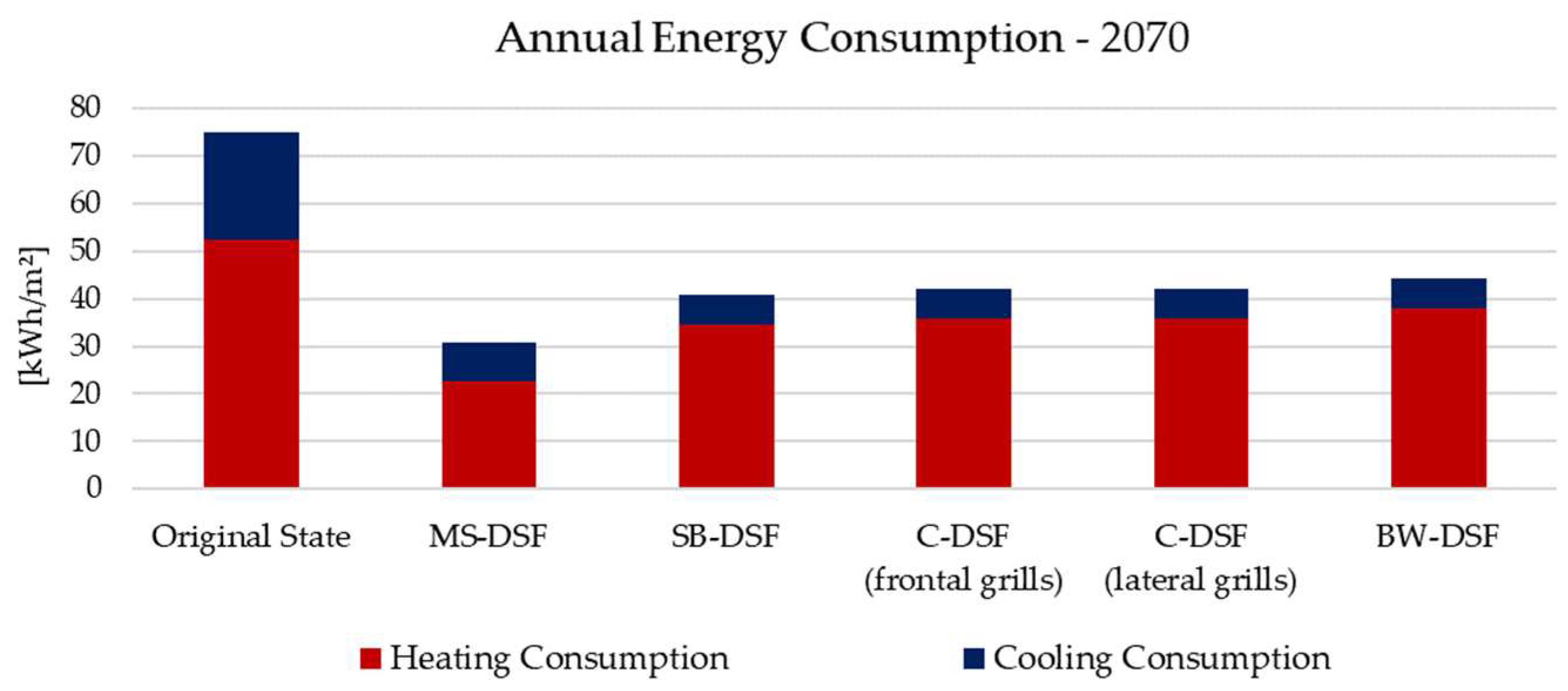
The energy consumptions, depicted from
Figure 8,
Figure 9 and
Figure 10, underline a constant increase in the building cooling load and a similar decrement in the heating need, and this happens for both the original state and with DSF configurations. Among the investigated typologies, the Multi-Storey DSF performs better than the others, allowing, at the same time, a good cooling reduction and a more intense heating decrement. Also the Shaft-box, Corridor and Box-Window configurations exhibit a general and quasi-identical energy reduction under future conditions. Moreover, deep differences are not underlined for the two analysed Corridor DSFs.
The evaluation of indoor thermal comfort is done according to the UNI EN 15251:2008 (CEN 2014) [
53], which associates comfort/discomfort rates to four categories. In detail, Category I has a high level of expectation, and it is recommended for spaces occupied by very sensitive people. Category II is for normal levels of expectations, suitable in case of new buildings or renovations. Category III represents a moderate, acceptable level of expectation and could be used for existing buildings, whereas the last, Category IV, involves the other conditions not referred to the previous cases. Moreover, the standard establishes for each comfort category a temperature interval, suggesting recommended indoor operative temperatures for the design of heating and cooling systems. These values are used to define each category’s upper and lower limits, as summarised in
Table 4. It is essential to underline that the here investigated parameter is referred to a building with a heating and cooling system. Thus, the performed simulations aim to evaluate its effectiveness in guaranteeing acceptable comfort rates inside the occupied spaces.
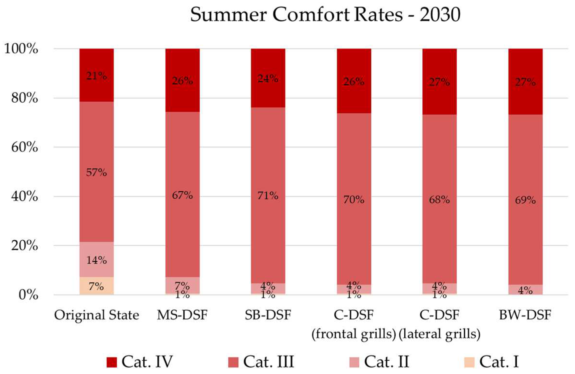
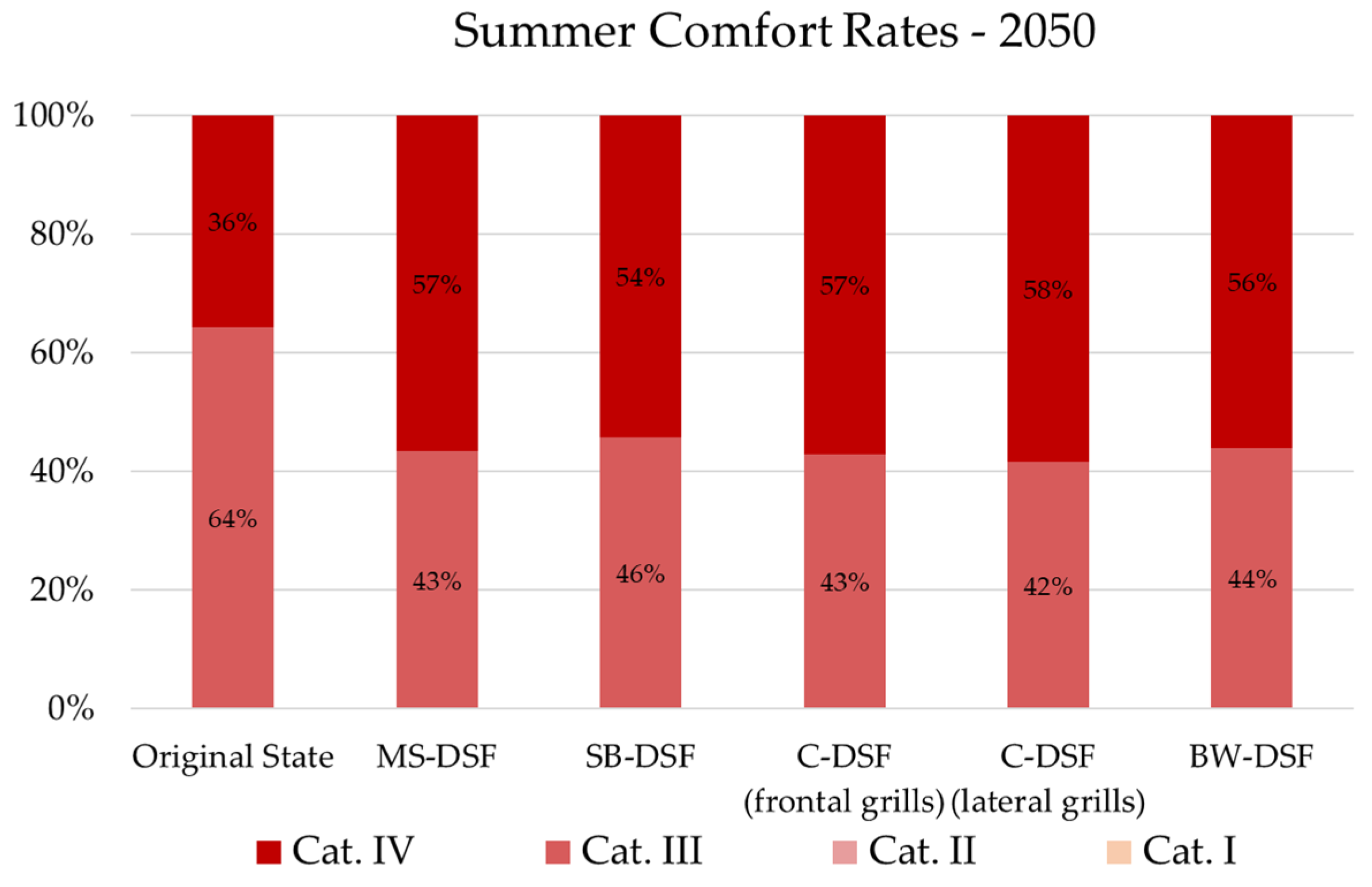
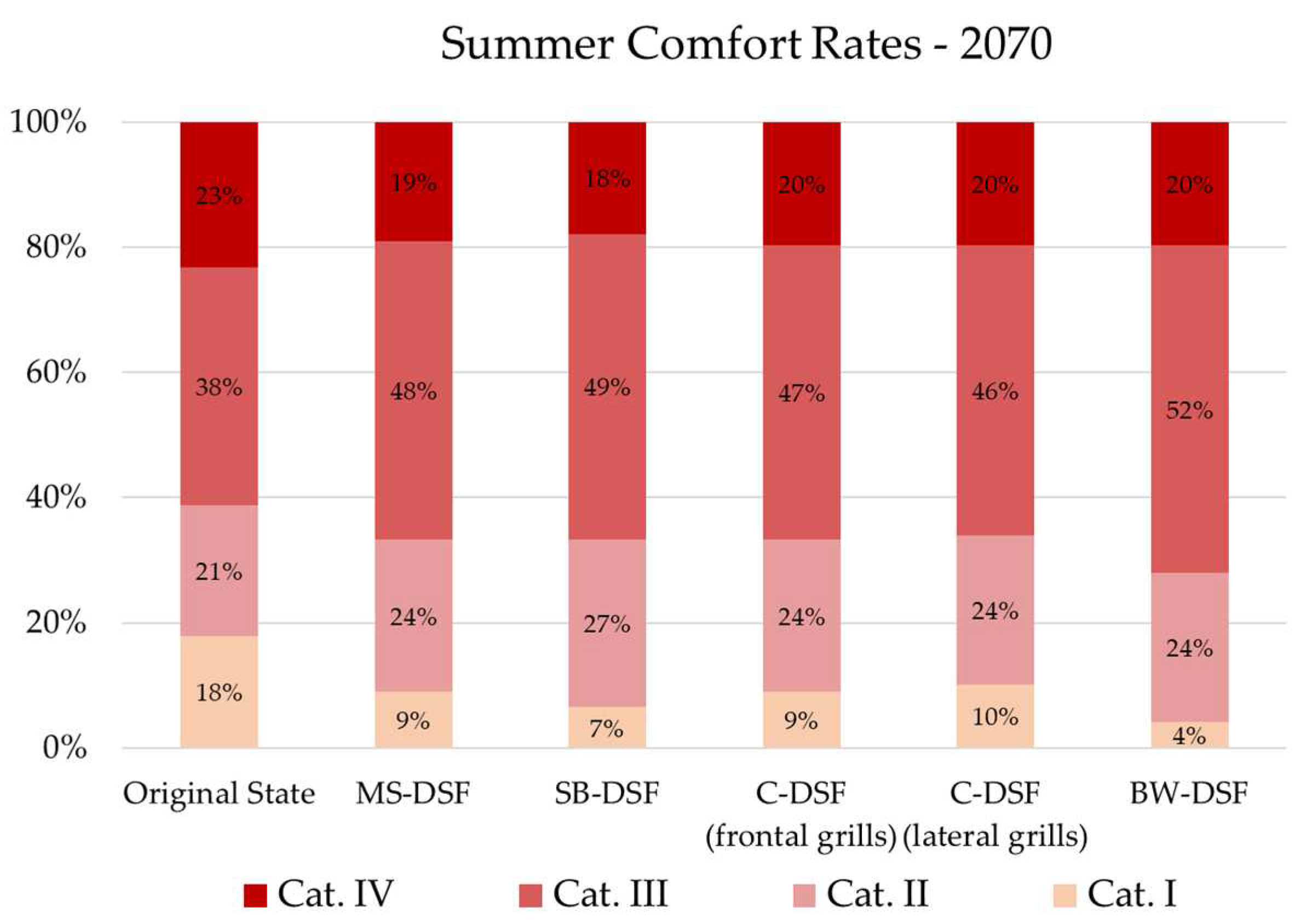
The thermal comfort analysis is plotted from
Figure 11,
Figure 12,
Figure 13,
Figure 14,
Figure 15 and
Figure 16. The comparisons underline several variations which should be taken into account for further considerations about the effectiveness of DSF systems. The estimated summer performance of Double Façades could lead to a different distribution of future comfort levels, due to higher picks reachable by the global solar radiation. As highlighted in the previous section, the amount of monthly mean radiation expected for the years 2030, 2050 and 2070 is much more significant than actual conditions, and this can generate the worst comfort rates for various DSF typologies. Due to a high solar load, the Double Façade, in fact, becomes a heated element, which continually emits the accumulated heat. This element is much more sensitive to this phenomenon than the original building envelope because it is entirely made of glazed surfaces. If from one side the DSF acts as a heat damper, reducing the effect of solar picks on the inner operative temperature, it also tends to enlarge the number of hours for which higher temperatures are estimated and, consequently, lower level of comfort. A mechanical system should be introduced to improve the summer indoor environment and to help natural ventilation in case of extra loads, converting the DSF into hybrid technology.
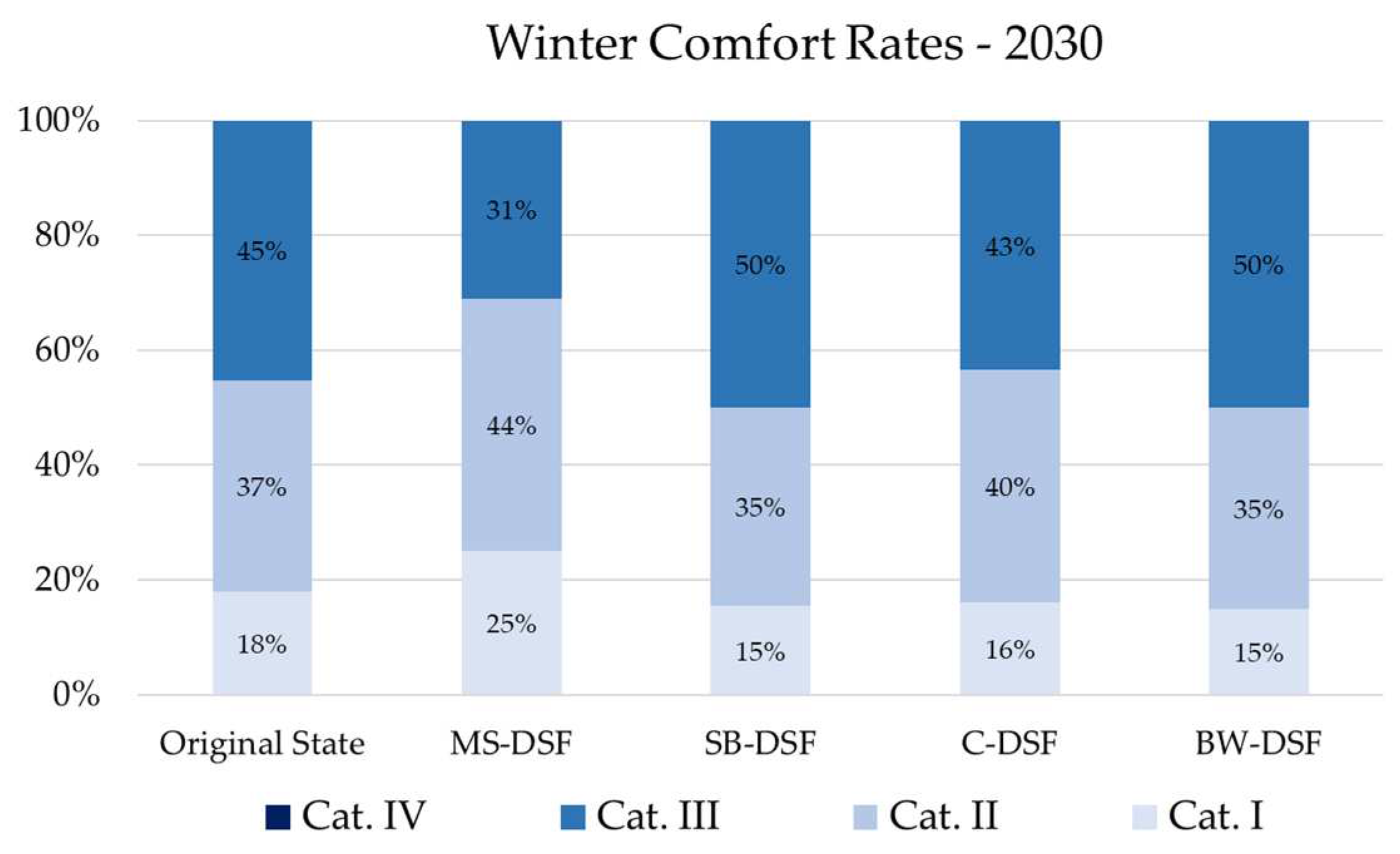
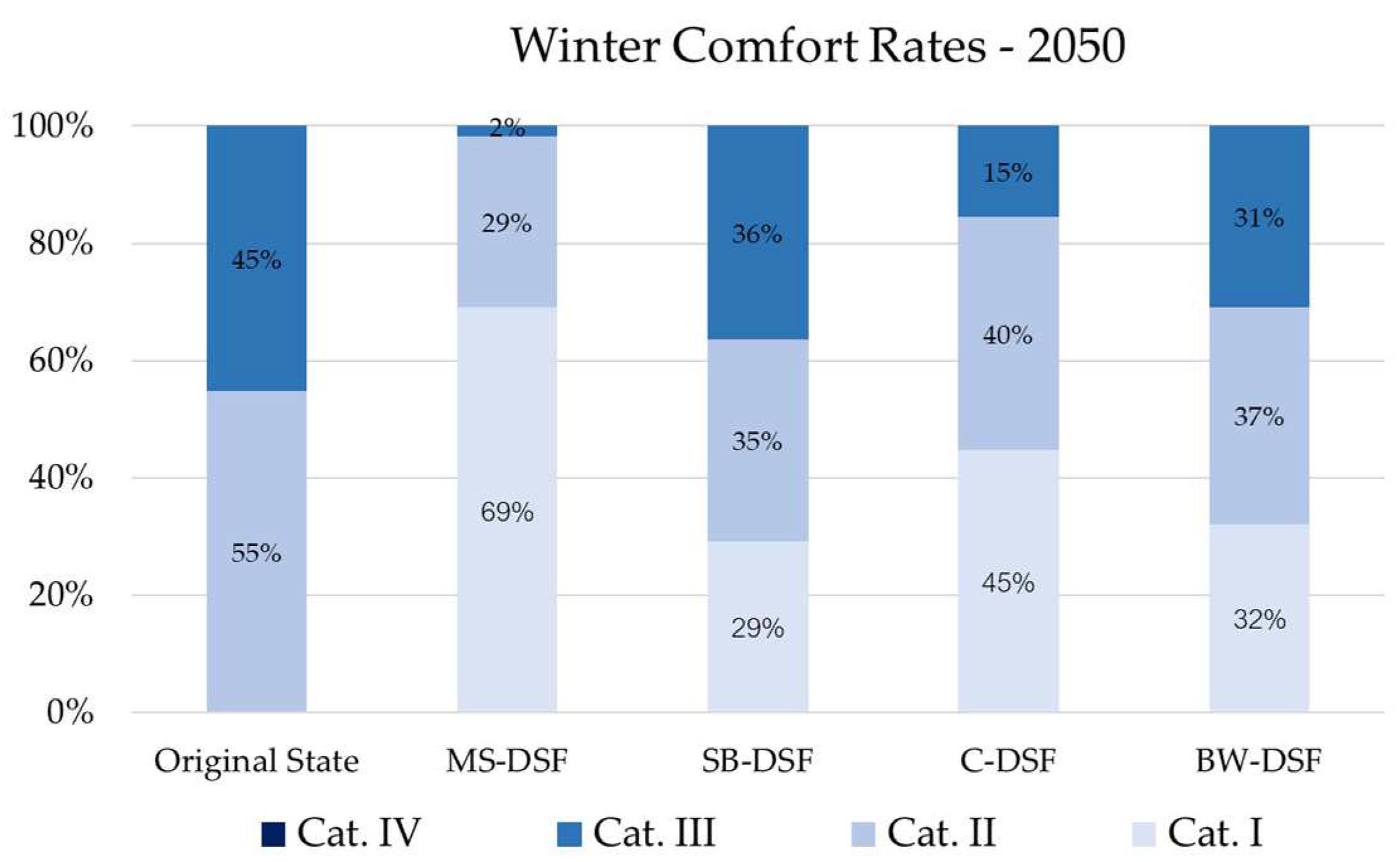
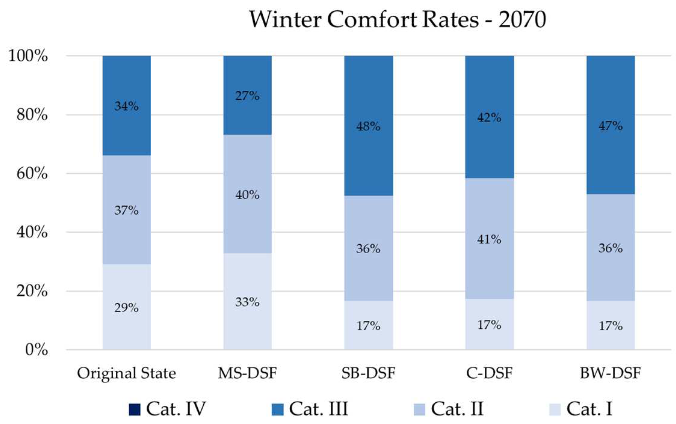
Evaluating winter comfort rates (
Figure 14,
Figure 15 and
Figure 16), the general temperature increase predicted for the coldest months allows the increment of best levels of expectation and this is estimated for both the building’s original state and after the DSF insertion. The discomfort rates referred to future conditions tend, in fact, to decrease, and this reduction assumes more significant values for DSF systems, ensuring better performances than those reachable by the reference building in its original state. Also in this case, the DSF that allows the best indoor environment is the Multi-Storey, which is capable of guaranteeing the highest percentage with a better level of expectations. Moreover, it is interesting to note that the winter comfort referred to the year 2050 shows better values than 2070. The explanation of this phenomenon stands in the higher temperatures and solar radiation predicted for the investigated period (January), which positively affect the heating side, reducing its load.
5. Conclusions
The present research aimed to assess the climate change vulnerability of a residential building located in Pescara, central Italy. The energy performance of the case study was evaluated by considering its current and improved version through dynamic energy simulations. The building energy requirement, subdivided into cooling and heating needs, and the indoor thermal comfort rates were estimated under future climate conditions in order to establish the best DSF retrofit solution. Thus, typical meteorological years were generated using regional climate models and the main weather parameters expected for 2030, 2050 and 2070 were defined.
The main results underline the impact that the continuous increase in temperature and solar radiation have on energy consumption, analysing both the heating and cooling needs. Lower winter energy loads are, in fact, estimated for the investigated years in comparison to current weather conditions. In contrast, higher cooling consumption will be necessary for ensuring satisfactory comfort rates inside the occupied spaces. By inserting the DSF on the north and south elevations, the total building energy requirement is deeply cut down, with benefits throughout the year. Among the investigated DSF configurations, the Multi-Storey typology ensures the best performance with energy reductions on the cooling and heating side.
Moreover, the insertion of the Double Façade positively affects the comfort rates, especially during the wintertime. Better ranges are, in fact, estimated in the energy-improved version, and, also in this case, the Multi-Storey configuration confirms to be the best solution in comparison to the others. The summer comfort conditions, instead, underline the weakness of these systems associated with elevating temperature and solar radiation levels. For avoiding the overheating risk of the DSF cavity with consequent discomfort rates expected inside the inner spaces, mechanical ventilation should be introduced thus helping the natural convection in the case of extreme thermal loads. In view of the achieved results, the use of multi-layer façades for the energy retrofit of existing buildings proves to be a proper option with savings in terms of energy requirement and comfort rates.
Author Contributions
All authors have equally contributed to the work and agree with its submission.
Funding
This research was developed in the framing of the Italian Research Project “Soluzioni integrate energetiche e antisismiche per costruzioni edili”, in the meaning of the PON action “Dottorati Innovativi con caratterizzazione Industriale”, funded by the Italian Ministry for the Economic Development.
Data Availability Statement
Not applicable.
Conflicts of Interest
The authors declare no conflict of interest.
References
- Mazzarella, L. Energy retrofit of historic and existing buildings. The legislative and regulatory point of view. Energy Build. 2015, 95, 23–31. [Google Scholar] [CrossRef]
- European Environment Agency. The European Environment—State and outlook 2020. Knowledge for the Transition to a Sustainable Europe. European Union, 2019, 1–499.
- Buildings Performance Institute Europe (BPIE). Europe’s Building under the Microscope. A country-by-country review of the energy performance of buildings; Buildings Performance Institute: Brussel, Belgium, 2011. [Google Scholar]
- UN Environment and International Energy Agency. Towards a Zero-Emission, Efficient, and Resilient Buildings and construction Sector. Global Status Report 2017; UN Environment, 2017, 1-48.
- Directive 2002/91/EC of the European Parlament and of the Council of 16 December 2002 on the Energy Performance of Buildings. Official Journal of the European, Communities; L. 1/65, 4.1. Directive 2002/91/EC of the European Parlament and of the Council of on the Energy Performance of Buildings. Official Journal of the European Communities; L. 1/65, 4.1.2003. 16 December.
- Directive 2010/31/EU of the European Parlament and of the Council of on the Energy Performance of Buildings (Recast). Official Journal of the European Union. L.153/13; 18.6.2010. 19 May.
- Directive 2012/27/EU of the European Parlament and of the Council of on Energy Efficiency, Amending Directives 2009/125/EC and 2010/30/EU and Replaing Directives 2004/8/EC and 2006/32/EC. Official Journal of the European Union. L.315/1, 14. 16 December.
- Buildings Performance Institute Europe (BPIE). State of the Building Stock- Briefing; Buildings Performance Institute: Brussel, Belgium, 2012. [Google Scholar]
- Oh, M.; Lee, C.; Park, J.; Lee, K.; Tae, S. Evaluation of Energy and Daylight Performance of Old Office Buildings in South Korea with Curtain Walls Remodeled Using Polymer Dispersed Liquid Crystal (PDLC) Films. Energies 2019, 12, 3679. [Google Scholar] [CrossRef]
- Moreno. ; Chemisana, D.; Vaillon, R.; Riverola, A.; Solans, A. Energy and Luminous Performance Investigation of an OPV/ETFE Glazing Element for Building Integration. Energies 2019, 12, 1870. [Google Scholar] [CrossRef]
- Sethi, M.; Lamb, W.; Minx, J.; Creutzig, F. Climate change mitigation in cities: a systematic scoping of case studies. Environ. Res. Lett. 2020, 15, 093008. [Google Scholar] [CrossRef]
- Kabisch, N.; Frantzeskaki, N.; Pauleit, S.; Naumann, S.; Davis, M.; Artmann, M.; Haase, D.; Knapp, S.; Korn, H.; Stadler, J.; et al. Nature-based solutions to climate change mitigation and adaptation in urban areas: perspectives on indicators, knowledge gaps, barriers, and opportunities for action. Ecol. Soc. 2016, 21. [Google Scholar] [CrossRef]
- Ricci, R.; Vitali, D.; Montelpare, S. An innovative wind–solar hybrid street light: development and early testing of a prototype. Int. J. Low-Carbon Technol. 2014, 10, 420–429. [Google Scholar] [CrossRef]
- Poirazis, H. Double Skin Façades: a Literature Review. Lund University, Lund Institute of Technology Department of Architecture and Built Environment: Sweden, 2006; 1–252.
- Uuttu, S. Study of Current Structures in Double-Skin Façades. Helsinki University of Technology, 2001.
- Heimrath, R.; Hengsberger, H.; Mach, T.; Streicher, W.; Waldner, R.; Flamant, G.; Loncour, X.; Guarracino, G.; Erhorn, H.; Erhorn-Kluttig, H.; Santamouris, M.; Farou, I.; Duarte, R.; Blomsterberg, A.; Sjöberg, L.; Blomquist, C. BESTFAÇADE. Best Practice for Double Skin Façades. WP 1 Report “State of the Art”; EIE/04/135/S07.38652; 2005; 1–151.
- Perino, M. State-of-the-Art Review Responsive Building Elements. Conference Paper, Vol. 2A, 2008; 1–198; http://www.ecbcs.org/annexes/annex44.htm#p.
- Zhai, Z.; Chen, Q.; Haves, P.; Klems, J.H. On approaches to couple energy simulation and computational fluid dynamics programs. J. Affect. Disord. 2002, 37, 857–864. [Google Scholar] [CrossRef]
- Lops, C.; Germano, N.; Ricciutelli, A.; D’alessandro, V.; Montelpare, S. Naturally Ventilated Double Skin Façades: Comparisons Between Different CFD Models. Math. Model. Eng. Probl. 2021, 8, 837–846. [Google Scholar] [CrossRef]
- Germano, N.; Lops, C.; Montelpare, S.; Camata, G.; Ricci, R. Determination of Wind Pattern Inside an Urban Area Through a Mesoscale-Microscale Approach. Math. Model. Eng. Probl. 2020, 7, 515–519. [Google Scholar] [CrossRef]
- Chan, L.S.A.; Chow, T.T.; Fong, K.; Lin, Z. Investigation on energy performance of double skin façade in Hong Kong. Energy Build. 2009, 41, 1135–1142. [Google Scholar] [CrossRef]
- Gratia, E.; De Herde, A. The most efficient position of shading devices in a double-skin facade. Energy Build. 2007, 39, 364–373. [Google Scholar] [CrossRef]
- Joe, J.W.; Choi, W.J.; Huh, J.H. Operation Strategies for an Office Building Integrated with Multi-Story Double Skin Façades in the Heating Season. Proceedings of Building Simulation 2011: 12th Conference of International Building Performance Simulation Association, Sydney, 14-. 16 November.
- Ding, W.; Hasemi, Y.; Yamada, T. Natural ventilation performance of a double-skin façade with a solar chimney. Energy Build. 2004, 37, 411–418. [Google Scholar] [CrossRef]
- Gontikaki, M. Optimization of a Solar Chimney Design to Enhance Natural Ventilation in a Multi-Storey Office Building. Proceedings of the 10th International Conference for Enhanced Building Operations, Kuwait, 26-. 28 October.
- Abraham, S.B.; Ming, T.Z. Numerical analysis on the thermal performance of a building with solar chimney and double skin façade in tropical country. IOP Conf. Series: Mater. Sci. Eng. 2018, 453, 012030. [Google Scholar] [CrossRef]
- Stec, W.; van Paassen, A.; Maziarz, A. Modelling the double skin façade with plants. Energy Build. 2005, 37, 419–427. [Google Scholar] [CrossRef]
- de Gracia, A.; Navarro, L.; Castell, A.; Cabeza, L.F. Energy performance of a ventilated double skin facade with PCM under different climates. Energy Build. 2015, 91, 37–42. [Google Scholar] [CrossRef]
- Johny, A.E. Optimization of Double-Skin Facades for High-Rise Buildings in Hot Arid Climates. Int. J. Environ. Sustain. 2018, 7. [Google Scholar] [CrossRef]
- Gaillard, L.; Giroux-Julien, S.; Ménézo, C.; Pabiou, H. Experimental evaluation of a naturally ventilated PV double-skin building envelope in real operating conditions. Sol. Energy 2014, 103, 223–241. [Google Scholar] [CrossRef]
- Athienitis, A.K.; Buonomano, A.; Ioannidis, Z.; Kapsis, K.; Stathopoulos, T. Double Skin Façades Integrating Photovoltaics and Active Shadings: a Case Study for Different Climates. 1st International Conference on Building Integrated Renewable Energy Systems, Dublin, 17. 20 March.
- Luo, Y.; Zhang, L.; Wang, X.; Xie, L.; Liu, Z.; Wu, J.; Zhang, Y.; He, X. A comparative study on thermal performance evaluation of a new double skin façade system integrated with photovoltaic blinds. Appl. Energy 2017, 199, 281–293. [Google Scholar] [CrossRef]
- Jayathissa, P.; Luzzatto, M.; Schmidli, J.; Hofer, J.; Nagy, Z.; Schlueter, A. Optimising building net energy demand with dynamic BIPV shading. Appl. Energy 2017, 202, 726–735. [Google Scholar] [CrossRef]
- Moon, K.S. Structural Design of Double Skin Facades as Damping Devices for Tall Buildings. Procedia Eng. 2011, 14, 1351–1358. [Google Scholar] [CrossRef]
- Zhang, R. SMART BUILDINGS: An Integrative Double Skin Façade Damper System For Structural Safety and Energy Efficiency. Doctoral Dissertation, University of New Hampshire, Durham, 2017. [Google Scholar]
- Takeuchi, T.; Yasuda, K.; Iwata, M. Studies on Integrated Building Facade Engineering with High-Performance Structural Elements. IABSE Symposium, Budapest 2006: Responding to Tomorrow’s Challenges in Structural Engineering. LOCATION OF CONFERENCE, HungaryDATE OF CONFERENCE;
- Scuderi, G. Adaptative Exoskeleton for the Integrated Retrofit of Social Housing Buildings. Doctoral Dissertation, University Of Trento, Trento, February 2016. [Google Scholar]
- Passoni, C.; Belleri, A.; Marini, A.; Riva, P. Sustainable Restoration of Post-WWII European Reinforced Concrete Buildings. 16th World Conference on Earthquake, Santiago Chile, 9-. 13 January.
- Labò, S. Holistic Sustainable Renovation of Post-World War II Reinforced Concrete Building Under A Life Cycle Perspective by Means Diagrid Exoskeletons. Doctoral Dissertation, University of Bergamo, Bergamo, March 2019. [Google Scholar]
- Khabir, S.; Vakilinezhad, R. Energy and thermal analysis of DSF in the retrofit design of office buildings in hot climates. Arch. Eng. Des. Manag. 2022, 19, 642–664. [Google Scholar] [CrossRef]
- Ascione, F.; Bianco, N.; Iovane, T.; Mastellone, M.; Mauro, G.M. The evolution of building energy retrofit via double-skin and responsive façades: A review. Sol. Energy 2021, 224, 703–717. [Google Scholar] [CrossRef]
- Sarihi, S.; Saradj, F.M.; Faizi, M. A Critical Review of Façade Retrofit Measures for Minimizing Heating and Cooling Demand in Existing Buildings. Sustain. Cities Soc. 2020, 64, 102525. [Google Scholar] [CrossRef]
- Sarihi, S.; Saradj, F.M.; Faizi, M. A Critical Review of Façade Retrofit Measures for Minimizing Heating and Cooling Demand in Existing Buildings. Sustain. Cities Soc. 2020, 64, 102525. [Google Scholar] [CrossRef]
- Montelpare, S.; D’alessandro, V.; Lops, C.; Costanzo, E.; Ricci, R. A Mesoscale-Microscale approach for the energy analysis of buildings. J. Physics: Conf. Ser. 2019, 1224. [Google Scholar] [CrossRef]
- Peel, M.C.; Finlayson, B.L.; McMahon, T.A. Updated world map of the Köppen-Geiger climate classification. Hydrol. Earth Syst. Sci. 2007, 11, 1633–1644. [Google Scholar] [CrossRef]
- Fondazione Osservatorio Meteorologico Milano Duomo ETS. https://www.fondazioneomd.it/climate-network.
- Pernigotto, G.; Prada, A.; Cóstola, D.; Gasparella, A.; Hensen, J.L. Multi-year and reference year weather data for building energy labelling in north Italy climates. Energy Build. 2014, 72, 62–72. [Google Scholar] [CrossRef]
- Bubnovà, R. Integration of the Fully Elastic Equations Cast in the Hydrostatic Pressure Terrain-Following Coordinate in the Framework of the ARPAGE/Aladin NWP SYstem. Am Meteorol Soc. 1995, 123, 515–35; [Google Scholar] [CrossRef]
- Farda, A.; Déué, M.; Somot, S.; Horányi, A.; Spiridonov, V.; Tóth, H. Model ALADIN as regional climate model for Central and Eastern Europe. Stud. Geophys. et Geod. 2010, 54, 313–332. [Google Scholar] [CrossRef]
- Horanyi, A.; Ihasz, I.; Radnoti, G. ARPEGE/ALADIN : A numerical Weather Prediction Model for Central-Europe with the Participation of the Hungarian Meteorological Service. IdoJárás 1996, 100, 277–301. [Google Scholar]
- Huth, R.; Mládek, R.; Metelka, L.; Sedlák, P.; Huthová, Z.; Kliegrová, S.; Kyselý, J.; Pokorná, L.; Halenka, T.; Janoušek, M. On the Integrability of Limited-Area Numerical Weather Prediction Model ALADIN over Extended Time Periods. Stud. Geophys. et Geod. 2003, 47, 863–873. [Google Scholar] [CrossRef]
- Cebecauer, T.; Suri, M. Typical Meteorological Year Data: SolarGIS Approach. Energy Procedia 2015, 69, 1958–1969. [Google Scholar] [CrossRef]
- UNI EN 15251:2008—Criteri per la Progettazione dell’Ambiente Interno e per la Valutazione della Prestazione Energetica degli Edifici, in Relazione alla Qualità dell’Aria Interna, all’Ambiente Termico, all’Illuminazione e all’Acustica.
Figure 1.
The localisation of Pescara (left and middle) and the reference building (right).
Figure 1.
The localisation of Pescara (left and middle) and the reference building (right).
Figure 2.
Comparison among estimated and measured data for the model calibration.
Figure 2.
Comparison among estimated and measured data for the model calibration.
Figure 3.
Schematisation of the investigated DSFs: The Multi-Storey (a), Shaft-Box (b), Corridor (c & d) and Box-Window (e) configuration.
Figure 3.
Schematisation of the investigated DSFs: The Multi-Storey (a), Shaft-Box (b), Corridor (c & d) and Box-Window (e) configuration.
Figure 4.
Euro-CORDEX Domain and the coordinates of its corners.
Figure 4.
Euro-CORDEX Domain and the coordinates of its corners.
Figure 5.
Monthly mean values referred to the temperature.
Figure 5.
Monthly mean values referred to the temperature.
Figure 6.
Monthly mean values referred to global solar radiation.
Figure 6.
Monthly mean values referred to global solar radiation.
Figure 7.
Yearly mean values referred to temperature and global solar radiation.
Figure 7.
Yearly mean values referred to temperature and global solar radiation.
Figure 8.
Building annual energy consumption estimated for the year 2030.
Figure 8.
Building annual energy consumption estimated for the year 2030.
Figure 9.
Building annual energy consumption estimated for the year 2050.
Figure 9.
Building annual energy consumption estimated for the year 2050.
Figure 10.
Building annual energy consumption estimated for the year 2070.
Figure 10.
Building annual energy consumption estimated for the year 2070.
Figure 11.
Comfort rates for the typical summer week according to the 2030 climatic file.
Figure 11.
Comfort rates for the typical summer week according to the 2030 climatic file.
Figure 12.
Comfort rates for the typical summer week according to the 2050 climatic file.
Figure 12.
Comfort rates for the typical summer week according to the 2050 climatic file.
Figure 13.
Comfort rates for the typical summer week according to the 2070 climatic file.
Figure 13.
Comfort rates for the typical summer week according to the 2070 climatic file.
Figure 14.
Comfort rates for the typical winter week according to the 2030 climatic file.
Figure 14.
Comfort rates for the typical winter week according to the 2030 climatic file.
Figure 15.
Comfort rates for the typical winter week according to the 2050 climatic file.
Figure 15.
Comfort rates for the typical winter week according to the 2050 climatic file.
Figure 16.
Comfort rates for the typical winter week according to the 2070 climatic file.
Figure 16.
Comfort rates for the typical winter week according to the 2070 climatic file.
Table 1.
Description of building envelope components.
Table 2.
Input parameters used for simulations. For each thermal zone, the occupation density (people/m2), the minimum fresh air (l/s-person), the target illuminance (Lux), and the occupation schedule are shown.
Table 4.
Operative Temperature range for comfort categories.
Table 4.
Operative Temperature range for comfort categories.
| Category |
Winter Operative
Temperature Range |
Summer Operative
Temperature Range |
| I |
Toperative > 21°C |
Toperative ≤ 25.5°C |
| II |
20°C < Toperative ≤ 21°C |
25.5°C < Toperative ≤ 26°C |
| III |
18°C < Toperative ≤ 20°C |
26°C < Toperative ≤ 27°C |
| IV |
Toperative < 18°C |
Toperative > 27°C |
|
Disclaimer/Publisher’s Note: The statements, opinions and data contained in all publications are solely those of the individual author(s) and contributor(s) and not of MDPI and/or the editor(s). MDPI and/or the editor(s) disclaim responsibility for any injury to people or property resulting from any ideas, methods, instructions or products referred to in the content. |
© 2023 by the authors. Licensee MDPI, Basel, Switzerland. This article is an open access article distributed under the terms and conditions of the Creative Commons Attribution (CC BY) license (https://creativecommons.org/licenses/by/4.0/).
