1. Introduction
Sugarcane is the most important sugar crop, accounting for 80% of global sugar production[
1,
2]. At the same time, sugarcane is also an important crop for renewable energy, accounting for 26% of global bioethanol production[
2], and occupies an extremely important position in the agricultural economy. However, the mechanized harvesting rate of sugarcane remains relatively low, which will be classified into two main reasons. The first aspect is due to asexual reproduction characteristics of sugarcane. At present, the sugarcane adopts asexual reproduction to breed. Once an excellent transgenic individual plant is obtained, the population can be rapidly expanded through axillary bud propagation. Thereby, the growth of sugarcane in the coming year is usually to use the perennial root which reserved in the field ridges in the harvesting profile. Thus, in the process of mechanized harvesting, it is necessary to cut into the soil to ensure the integrity of the roots, which will pose a severe challenge to mechanized harvesting. The second aspect is the machine-harvested quality of sugarcane. Sugarcane is a long-stalked crop with complex and diverse growth forms in the field affected by typhoon. Generally, affected by typhoon sugarcane usually lodged. The top of a lodged sugarcane grew upward during subsequent growth period, resulting in curved stalk. Therefore, the sugarcane harvester poses various technical challenges such as breakage, blockage, and field losses during the harvesting process.
To address those issues, the sugarcane chopper harvester has gained widespread attention and utilization worldwide, due to its effective ability to harvest lodged sugarcane[
3,
4,
5,
6]. In general, the operating principle of the sugarcane chopper harvester involves three distinct processes, outlined as follows. As shown in
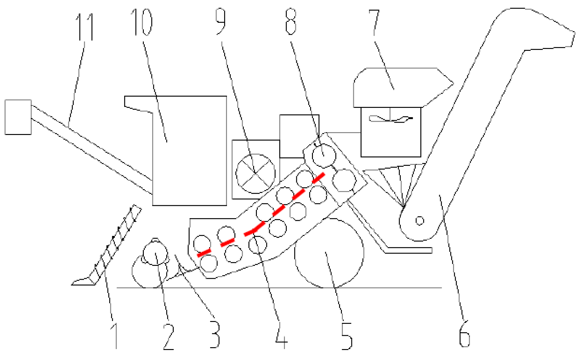
Figure 1, firstly, the sugarcane stalks are pushed over by a knockdown roller and then cut by the basecutter at their bases. Secondary, the cut-down sugarcane stalks are carried to the chopper by the basecutter and the feeding/conveying rollers train where the sugarcane stalks are chopped into billets. Finally, the billets are thrown to extractor to remove trash and then conveyed to the transporter via the billets elevator. It is noted that the path where the stalks and billets went through from basecutter to extractor is called channel in the paper. In order to convey the whole stalk sugarcanes effectively, currently, there are two types of channels available for sugarcane chopper harvesters, namely the "chopper rear-mounted channel" and the "chopper front-mounted channel" as described in the paper. Further details regarding these two channels are provided below.
(1) Chopper rear-mounted channel. This type of channel had several pairs of rollers between the basecutter and the chopper, and the chopper is closely followed by an extractor. A representative sugarcane harvester is CASE 8000 harvester, which has 5.5 pairs of rollers between its basecutter and chopper, as shown in
Figure 1. The symmetry line between upper and lower rollers, donated as a red dotted polyline line in
Figure 1, is the conveying track of sugarcanes[
7]. It is obvious that, with a chopper rear-mounted channel design layout, the lodged sugarcane stalks had to go through several pairs of feeding/conveying rollers, i.e., a long polyline track, from the basecutter to chopper during the harvesting profile. Therefore, more pairs of rollers increased the risk of curved stalks broken and the channel blocked [
8].
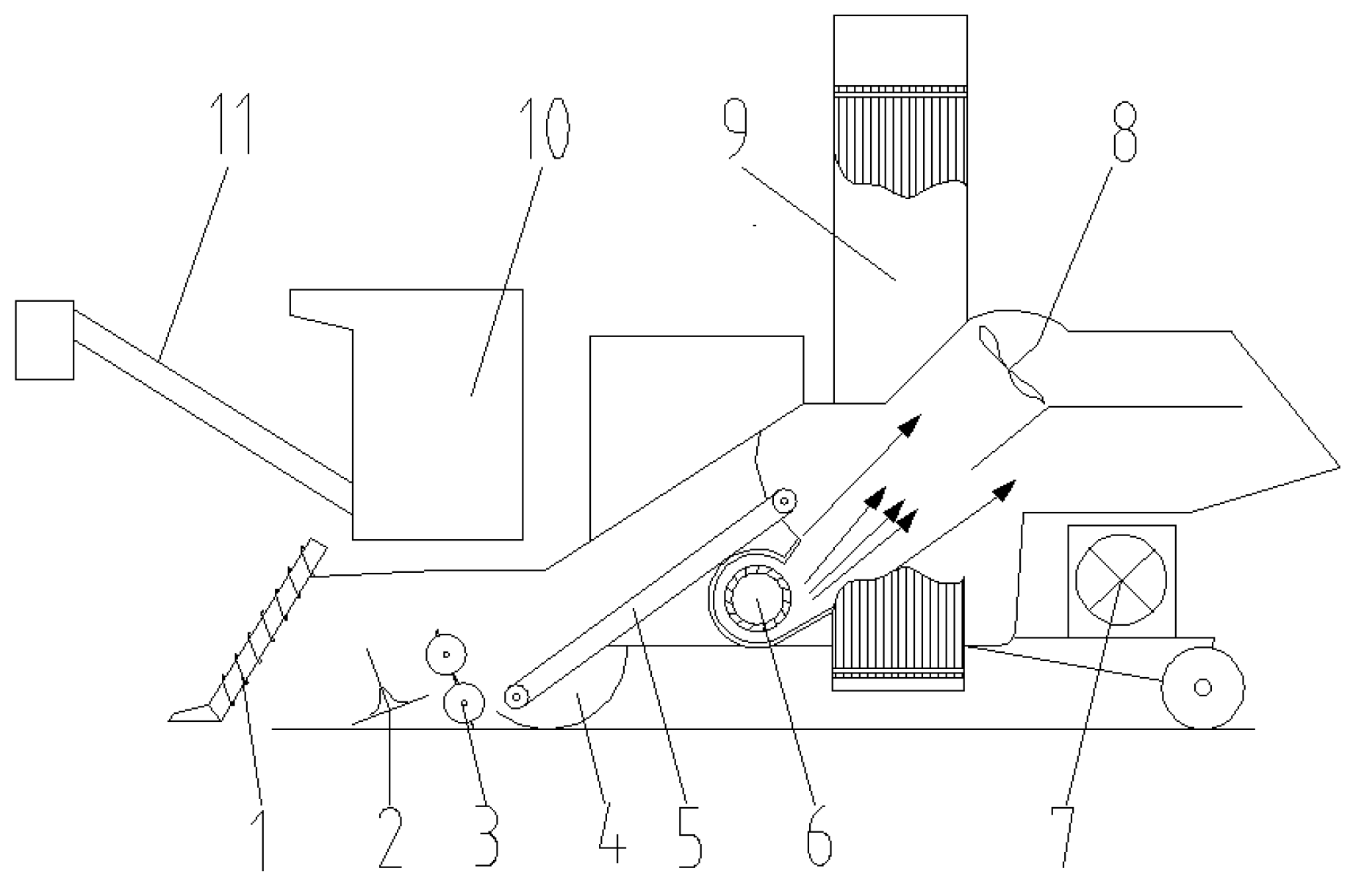
(2) Chopper front-mounted channel. As described in
Figure 2, there are no rollers between the basecutter and chopper. The chopper directly follows the basecutter, while the billet conveying device is directly mounted after the chopper. In addition, the billet conveying device is followed by an extractor. A representative sugarcane harvester is Class CC3000 harvester as shown in
Figure 2. Under this design structure, the curved lodged stalks can directly be carried to the chopper by the basecutter, and then chopped into billets. Such that, there is no chance for curved stalks to block the channel. Compared with the chopper rear-mounted channel, therefore, the chopper front-mounted channel has a grate adaptability to the curved lodged sugarcaner stalks. However, experiments shows that quite a few billets are dropped into the field, and some the billets are easy chopped back by the chopper. Moreover, the billets can not chopped to uniform length (or the length required by the sugar factory). To work out these problems, some scholars try to optimize the chopper front-mounted channel, but the revised machines do not achieve desired effects. Thus, this kind of harvester is not widely used in the world [
9,
10].
Additionally, there have been numerous studies focusing on various aspects of sugarcane harvester operations, such as lifting lodged canes, improving the cutting quality of the basecutter, enhancing trash removal, and optimizing stalk swathing[
11,
12,
13,
14,
15,
16,
17]. For instance, [
14] investigates the effect of fan speed, cane feeding rate, and billet length on impurity rate and cane losses during sugarcane harvesting. The objective is to establish a theoretical basis for the research and development of sugarcane harvester extractors. Also, reference [
16] introduces and analyzes the trajectory of expelled billets from the chopping rollers of a sugarcane harvester, which provided a design guidance for the sugarcane harvester extractor and the chopper. In order to reduce the trash content and loss rate, Wu et al.[
17] develops three types of negative pressure structures for the sugarcane chopper harvester extractor based on the CFD numerical simulation method. However, those efforts are focused on the pre-stage (i.e., divider) or after-stage (e.g., extractor) devices of the conveying channel for the sugarcane harvester. Furthermore, some scholars explore techniques for effectively carrying whole stalks of sugarcane whole stalk harvester [
18,
19], and investigate the channel technology specifically related to sugarcane chopper harvesters, particularly the process of carrying sugarcane from basecutter to feeding rollers[
20,
21]. For example, Li et al.[
22] shows that the major factors in the conveying capacity of sugarcane harvester are the traction force on stalks, the lifting angle of stalks, and the rotary speed of conveying roller. However, those studies only focused on existing channels. Zhou et al.[
23] conducted a study on the impact of the relative positions of paired blades of chopping rollers on the chopping quality of the sugarcane harvester. But the study only aimed to identify the optimal chopping blades setting parameters that would result in improved chopping performance. The feeding/conveying roller train is one of the key components of harvester, and its conveying capacity affects the efficiency and performance of harvesting [
24]. Therefore, some further efforts should be paying attention to conveying channel of the sugarcane chopper harvester to improve the transmission capacity.
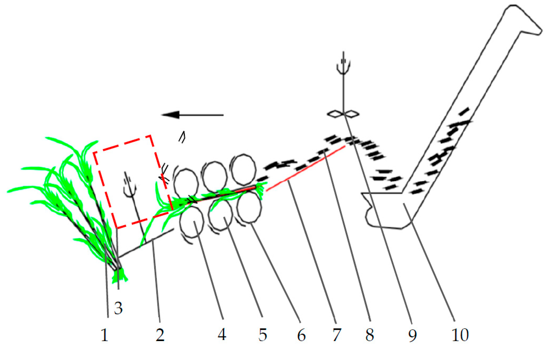
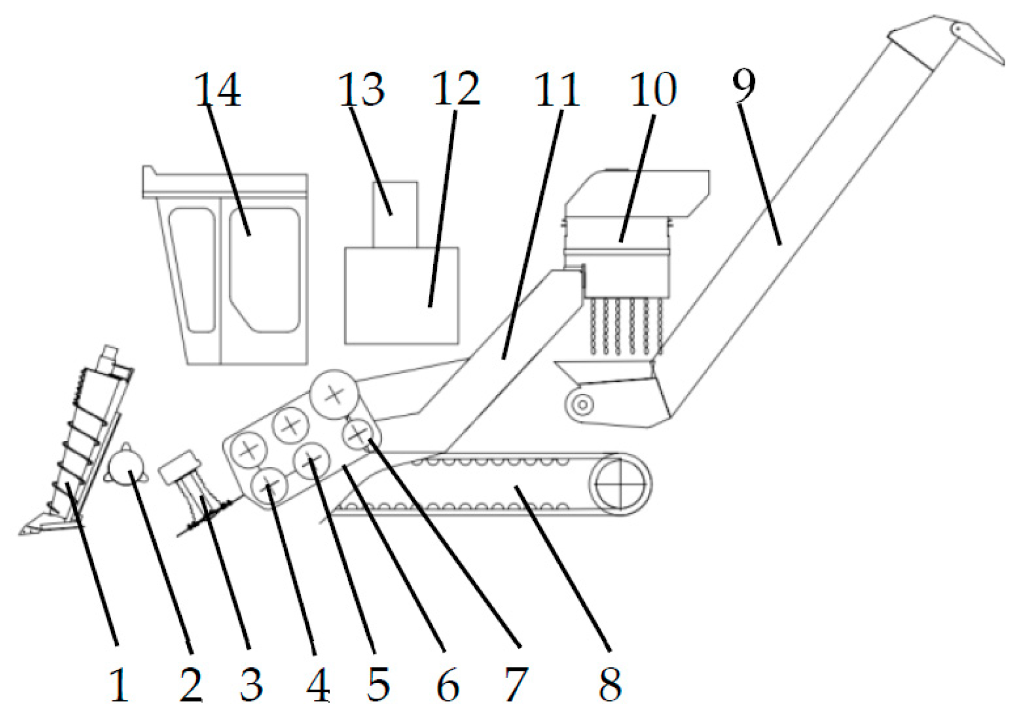
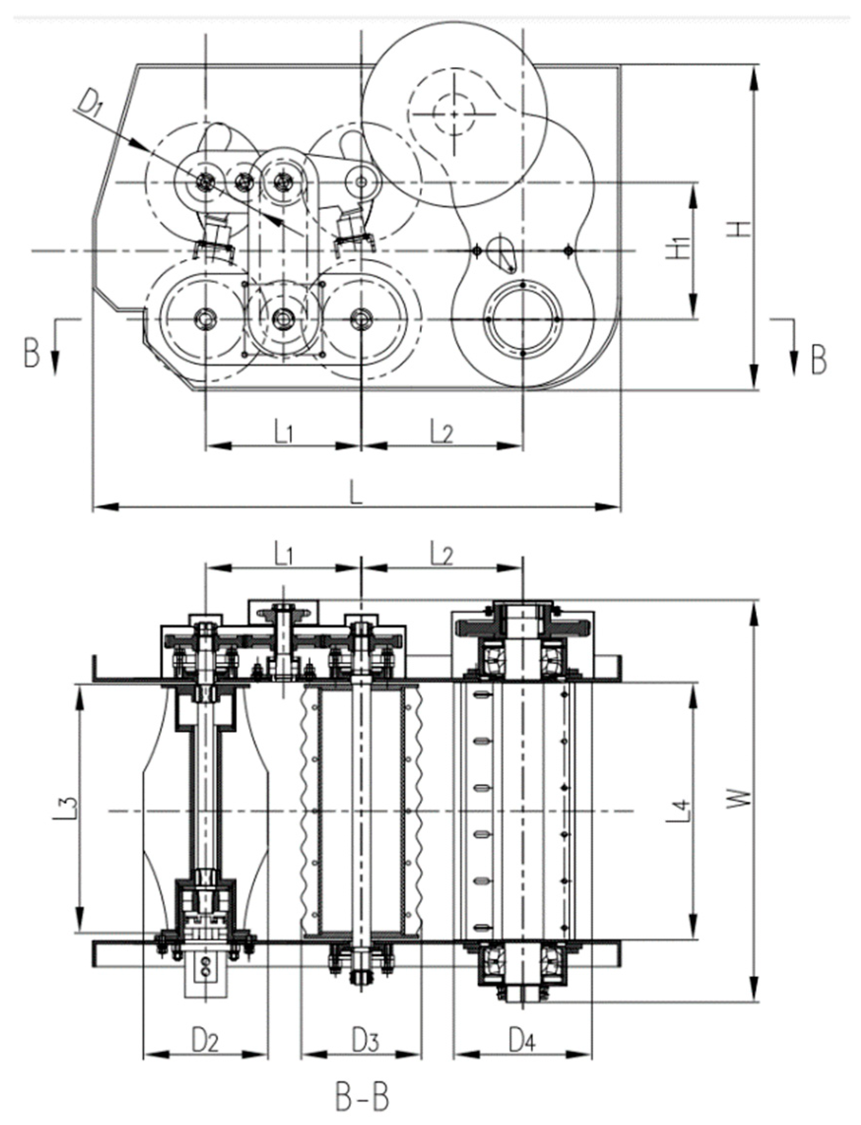
Based on the aforementioned analysis of the advantages and disadvantages of existing channels of sugarcane chopper harvester, a novel channel structure and design method are proposed for a sugarcane chopper harvester in this paper. The proposed channel consists of a feeding/conveying roller train, a chopper, and a billet conveying device. The chopper is mounted between the other two parts, thus named the "chopper centrally-mounted channel" in the paper. The feeding/conveying roller train is just designed with a pair of feeding rollers and a pair of conveying rollers, which can decrease the conveying path of channel significantly. Moreover, the chopper centrally-mounted channel has been applied to the HN4GDL-91 sugarcane chopper harvester which is developed by South China Agricultural University (SCAU) and tested for several years in the field. In addition, the structure of the basecutter and the mechanism carrying stalks to feeding rollers are studied via theoretical analysis and tests. The relationship between the basecutter and the chopper centrally-mounted channel is also conducted in systematic analysis in the paper.
4. Field tests
4.1. Test equipment and materials
(1) Test equipment
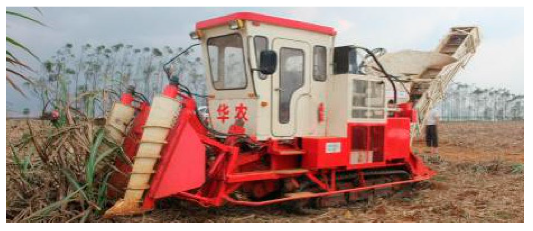
The test equipment included a HN4GDL-91 sugarcane chopper harvester with a proposed chopper centrally-mounted channel (as shown in
Figure 17), an electronic scale (precision: 0.01 kg), a photoelectric speed tester (DT2234C, range of 2.5–999999 RPM), a vernier caliper, a band tape, a protractor, a digital camera, a sugarcane machete and a shovel.
(2) Test materials
In January 2018, field tests are conducted in a sugarcane field in the Suixi Comprehensive Test Station of the China Sugarcane Research System. Affected by typhoon, sugarcane stalks in the field are badly lodged. The variety of sugarcane in the field is Yuetang 55. The row spacing in the field is 1.2 m. The planted density is in a range of 7–9 stalks/m. The average diameters of stalks at the position of its base, middle, and top are 23.46, 24.45, and 20.93 mm, respectively. The average length of stalks is approximately 2.23 m. Sugarcane stalks, which diameter and length are close to the average value in the field, are selected as test samples.
4.2. Test indexes
To get the harvesting performance of the chopper centrally-mounted channel of HN4GDL-91 harvester, feed quantity, field loss ratio, and qualified ratio of billets are selected as test indexes according to the test standard of the sugarcane harvester.
(1) Feed quantity
The feed quantity refers to the total mass of material which pass through sugarcane harvester in per unit time. The formula for calculating feed quantity is as follows.
where Q
w is feed quantity, kg/s;
Ws is the total mass of material which got from harvester in test plot, kg;
Wpa is the mass of the material which got from the extractor of harvester in test plot, kg; and t is the harvesting time in the plot, s.
(2) Field loss ratio
The field loss ratio
Sz (%) is the percentage of the total mass of sugarcane stems which left in field (
Wloss) after harvesting, to the total mass of sugarcane stems in test plot (
Wq). The calculation formula is as follows.
(3) Qualified ratio of the billets
The qualified ratio
Cdh (%) of the billets is the percentage of the total mass of the qualified billets which got from harvester to the total mass of all billets got from harvester in the test. The calculation formula is as follows.
where
Cdh is the qualified ratio of the billets, %;
Wdh is the total mass of the qualified billets in the test plot, kg; and
Wdz is the total mass of all billets in the test plot, kg.
4.3. Test method
Sometimes several stalks grew closely together in a clump for sugarcane tillering reason. So that, when harvesting in field, the feeding/conveying roller train should be able to go through multiple sugarcane stalks simultaneously. In this paper, lodged stalks in a clump are simulated by laying down several stalks closely together in the field and their bases all facing the same direction. Regarded those stalks as a group, and 3 group stalks are laid down in field one by one, as shown in
Figure 18. Since stalks entered feeding rollers in the way of the bases of stalks first, the 3 group stalks are harvested in the direction of from their bases to tops in tests.
The rotational speed of chopper, the number of sugarcane stalk in a group, the rotational speed of feeding/conveying rollers, and the ground speed of harvester are selected as test factors.
Table 3 listed the factors and their levels. L
27(3
13) orthogonal table is chosen to conduct the test (
Table 4). Each treatment is repeated three times and their averages are shown in
Table 4.
4.4. Results and analysis
The test results are indicated in
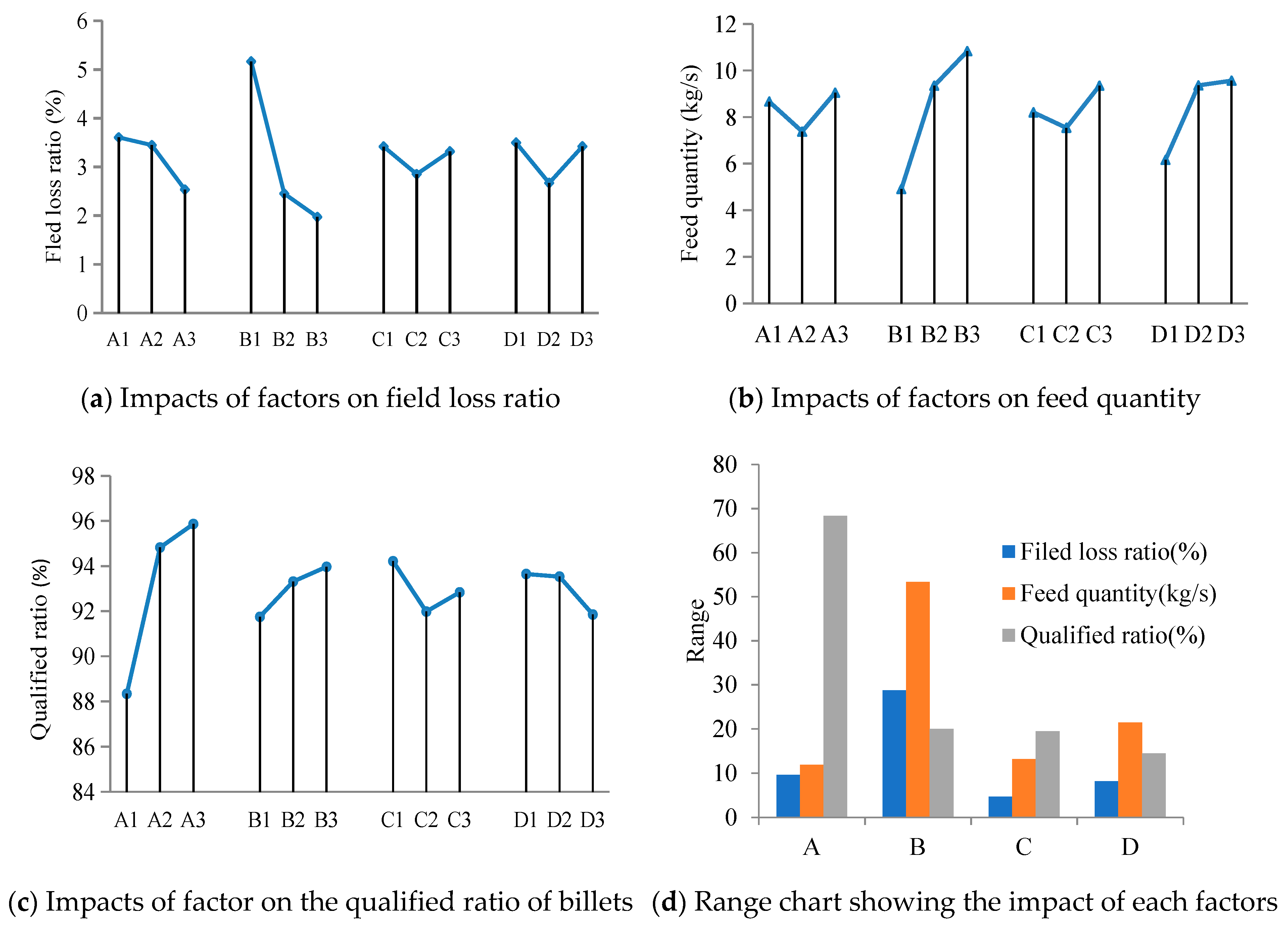
Table 4. Results of direct-vision analysis on the test results is as shown in
Figure 19. The results of variance analysis on the test results are indicated in
Table 5.
(1) Impacts of the factors on the field loss ratio
As shown in
Figure 19a, the field loss ratio decreased with the increase of levels of factors A and B. Higher rotational speed of the chopper (factor A) is helpful to improve the smoothness of moving stalks in the roller train. The results in
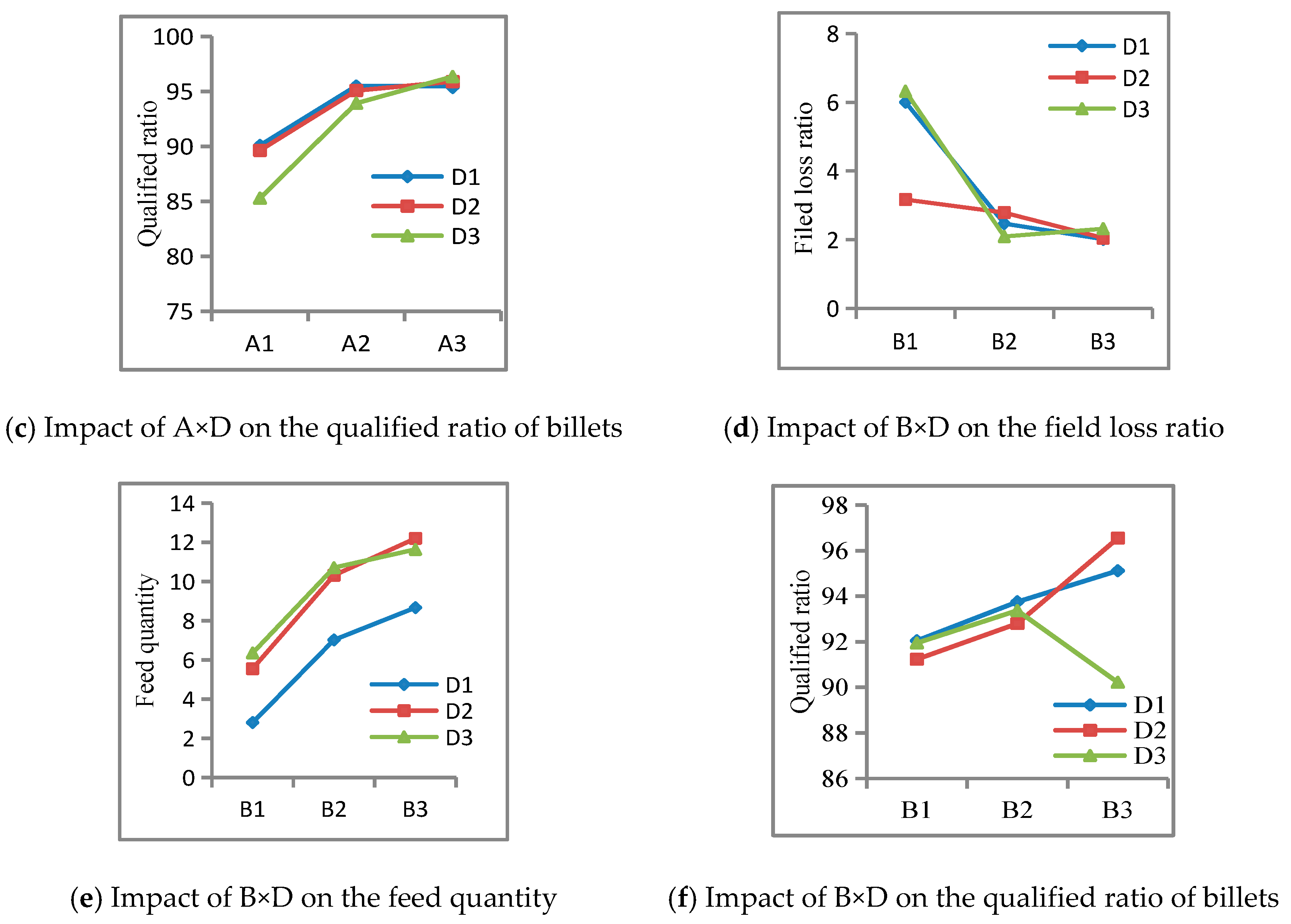
Figure 19d and
Table 5 showed that factor B (numbers of sugarcane stalk in a group) had a larger impact on the field loss ratio than factor A. That is because the basecutter could grab almost all stalks that contacted with its disc and carried those stalks to feeding rollers. Only very few stalks are left in the field which caused field loss. The results of variance analysis (
Table 5) showed that the factor B and the interactions A×D and B×D, had significantly affect on the field loss ratio, but other factors and interactions had no significant impact on it.
(2) Impacts of factors on the feed quantity
The results of variance analysis (
Table 5) showed that all the factor B, A×D and B×D, had significantly affect on feed quantity, but other factors had no significant impact on it. With the increase of levels of factors B and D, the feed quantity increased. Results of the test showed that the harvester could do a good job at the given levels of factor B and D in the test.
(3) Impacts of factor levels on the qualified ratio of billets
As shown in
Figure 19c, the qualified ratio of billets increased with the increase of levels of factors A and B. When the level of factor A (rotational speed of chopper) increased, the speed of blades of the chopper increased. Higher speed of chopping blades is helpful to cutting quality of billets. As factor B increases, the more stalks in feeding/conveying roller train, the stronger interaction force between the sugarcane and the rollers, which could reduce the sugarcane slide and is helpful to chopping. The results of variance analysis (
Table 5) showed that factors C and D had no significant impact on the qualified ratio of the billets. The factors of A and the interactions A×D and B×D had significantly impact on the qualified ratio of billets. The other factors and interactions had no significant impacts on it.
(4) Optimal combination of factors and their levels
Based on the results of direct-vision and variance analysis, we could confirm that both numbers of sugarcane stalk in a group (B) and the chopper rotational speed (A) had the greatest impact on the field loss ratio, feed quantity, and qualified ratio of billets. In addition, the factor B had the greatest impact on the field loss ratio and feed quantity. As for qualified ratio of billets, the influence of factor B is second only to that of factor A. Comparing factors A and C, factor A had a greater impact on the field loss ratio and the qualified ratio of billets than factor C. But as for the influence of the feed quantity, the performance of A and C are essentially the same. From the range analysis of the loss and feed quantity, the impact degree of factor D on the test indicators is greater than that of factor C. For the qualified ratio of billets, the impact degree of factor C on the test indicators is slightly greater than that of factor D. Therefore, for the three test indicators, i.e., the field loss ratio, feed quantity, and qualified ratio of billets, the comprehensive impact of each factor could be ordered as follows: B>A>D>C.
To determine the parameter combination that provided the best operational performance, the comprehensive balance method is used to analyze the best parameter combination. Based on the purpose of the test, the priority of indexes is given to the feed quantity and the qualified ratio of the billets, and then the field loss ratio is set to aid the analysis. Also, the factors that with significant interactions are given priority in the analysis of the interaction effects. The factors which had no significant interactions are analyzed in turn based on the priority order and impact degree of the performance indicators.
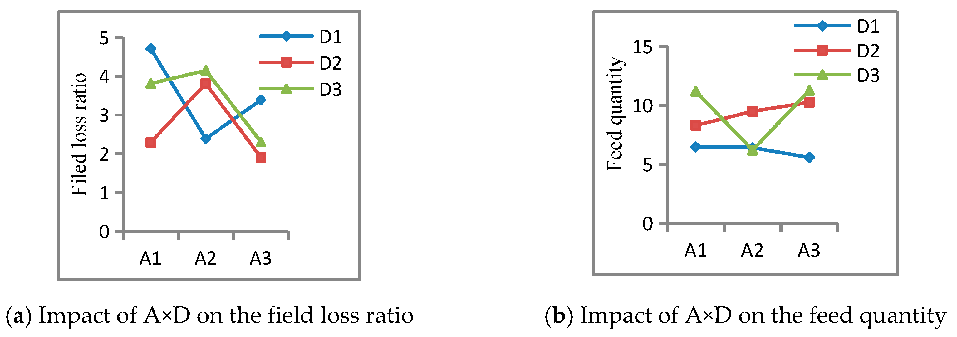
According to the above analysis, both the factors B and A reached optimal levels for all three indicators at its third level. Hence, it is determined that B3 and A3 are the optimal levels. The interactions of factors A×D and B×D significantly impacted on the 3 indicators. Therefore, the level of factor D should be analyzed on the basis of the interactions, as shown in
Figure 20.
From
Figure 20(a)–(c), we could conclude that, with the change of the level of factor A, factor D1 gave a greater change than D2 and D3, which indicated that the level D1 is unstable. Thus, D1 should be discarded. For priority indicators, both D2 and D3 achieved maximum values under A3. From an independent sample variance analysis of A3D2 and A3D3, these interactions had no significant difference in terms of the impact of priority indicators. Combined with the impact of factor D on the field loss ratio, the field loss ratio is the lowest at the D2 level, as shown in
Figure 19. Therefore, D2 is considered to provide the best results under the action of A×D. Moreover, it could be seen form
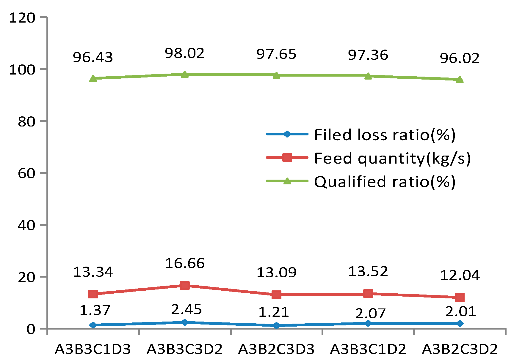
Figure 19d that the D2 level had a smaller impact on the feed quantity than the D3 level but a significant impact on the qualified ratio of billets. The field loss ratio of D2 is lower at the B3 level. Hence, both the two interaction results showed that the D2 level is appropriate for D. As for factor C, C1 and C3 are selected as alternative levels based on the condition of priority indicators. And the test results showed that the length of billets obtained at the C3 level are more in line with the length requirement Therefore, it could conclude that the optimal parameter combination is A3B3C3D2, which did not appear in the orthogonal test. Thus, further verification test of A3B3C3D2 should be conducted to compare with the several better combinations in the orthogonal test, as shown in
Figure 21.
According to the principle of priority given to the feed quantity and the qualified ratio of billets, the analysis in
Figure 21 showed that the A3B3C3D2 combination yields the optimal feed quantity and qualified ratio of billets. Although this combination had the highest field loss ratio, it is within the allowable range of sugarcane machine harvesting and had a large margin. Therefore, A3B3C3D2 is selected as the optimal combination which detail is as follows. The rotational speed of the chopper is 390 r/min, the feeding quantity is 10 stalks (approximately 12.96 kg), the rotational speed of feeding/conveying rollers is 230 r/min, and the ground speed of harvester is medium (1.09 m/s). Under this combination, the field loss ratio is 2.45%, the feed quantity is 16.66 kg/s, and the qualified ratio of billets is 98.02%.
5. Conclusions
In address various technical challenges such as breakage, blockage, and field losses for the sugarcane chopper harvester. In this paper, a novel concept and design method of conveying and chopping channel, named chopper centrally-mounted channel, is proposed for a sugarcane chopper harvester. The chopper centrally-mounted channel consisted of three parts: the feeding/conveying roller train, the chopper, and the billets conveying device. Notably, the chopper is mounted between other two parts. The feeding/conveying roller train incorporates a pair of feeding rollers and a pair of conveying rollers only, while the billets conveying device utilizes a scraper chain conveyor. This design layout not only significantly reduces the sugarcane conveying path, but also effectively improves the adaptability to lodged sugarcane and prevents billets from being chopped back by the chopper.
Furthermore, the paper encompasses the design of the basecutter structure and the analysis of the mounting relationship between the basecutter and the chopper centrally-mounted channel. The results of the theoretical analysis reveals that the inclination angle of the cutter disc should be 2o greater than the angle of the feeding conveying channel. Additionally, four factors are taken into consideration for evaluating the performance of the proposed chopper centrally-mounted channel in the filed orthogonal test. And the optimal combination of the four factors is determined as follows: the number of sugarcane stalks in a clump is 10, the ground speed of harvester is 1.09 m/s, the rotational speed of the chopper is 390 r/min, and the feeding/conveying roller is 230 r/min. With these optimal combination settings, the field loss ratio, the feed quantity, and the qualified ratio of the billets are 2.45%, 16.66 kg/s, and 98.02%, respectively. The conducted field test results validated the analysis and the proposed chopper centrally-mounted channel design in harvesting seriously lodged sugarcane smoothly and optimizing the overall performance of chopper harvester.
Figure 1.
Chopper rear-mounted channel of Case 8000 sugarcane harvester. 1 divider 2 knockdown roller 3 basecutter 4 feeding/conveying roller train 5 walking wheel 6 billets elevator 7 primary extractor fan 8 chopper 9 engine 10 cab 11 topper.
Figure 1.
Chopper rear-mounted channel of Case 8000 sugarcane harvester. 1 divider 2 knockdown roller 3 basecutter 4 feeding/conveying roller train 5 walking wheel 6 billets elevator 7 primary extractor fan 8 chopper 9 engine 10 cab 11 topper.
Figure 2.
Chopper front-mounted channel of Class CC3000 sugarcane harvester. 1 divider 2 basecutter 3 chopper 4 walking wheel 5 billets conveying device 6 extractor fan 7 engine 8 extractor fan 9 billet elevator 10 cab 11 topper.
Figure 2.
Chopper front-mounted channel of Class CC3000 sugarcane harvester. 1 divider 2 basecutter 3 chopper 4 walking wheel 5 billets conveying device 6 extractor fan 7 engine 8 extractor fan 9 billet elevator 10 cab 11 topper.
Figure 3.
Chopper centrally-mounted channel of sugarcane harvester. 1 sugarcane 2 basecutter 3 feeding/conveying roller train 4 feeding roller 5 conveying roller 6 chopper 7 billets conveying device 8 billet 9 extractor fan 10 billet elevator.
Figure 3.
Chopper centrally-mounted channel of sugarcane harvester. 1 sugarcane 2 basecutter 3 feeding/conveying roller train 4 feeding roller 5 conveying roller 6 chopper 7 billets conveying device 8 billet 9 extractor fan 10 billet elevator.
Figure 4.
Structural scheme of HN4GDL-91 sugarcane harvester. 1 divider 2 knockdown roller 3 basecutter 4 feeding roller 5 conveying roller 6 feeding/conveying rollers train 7 chopper 8 crawler wheel 9 billet elevator 10 extractor 11 billets conveying device 12 engine 13 hydraulic oil cooling fan 14 cab.
Figure 5.
Structure diagrams of chopper centrally-mounted channel.
Figure 5.
Structure diagrams of chopper centrally-mounted channel.
Figure 6.
Basecutter of John Deere 3520 harvester.
Figure 6.
Basecutter of John Deere 3520 harvester.
Figure 7.
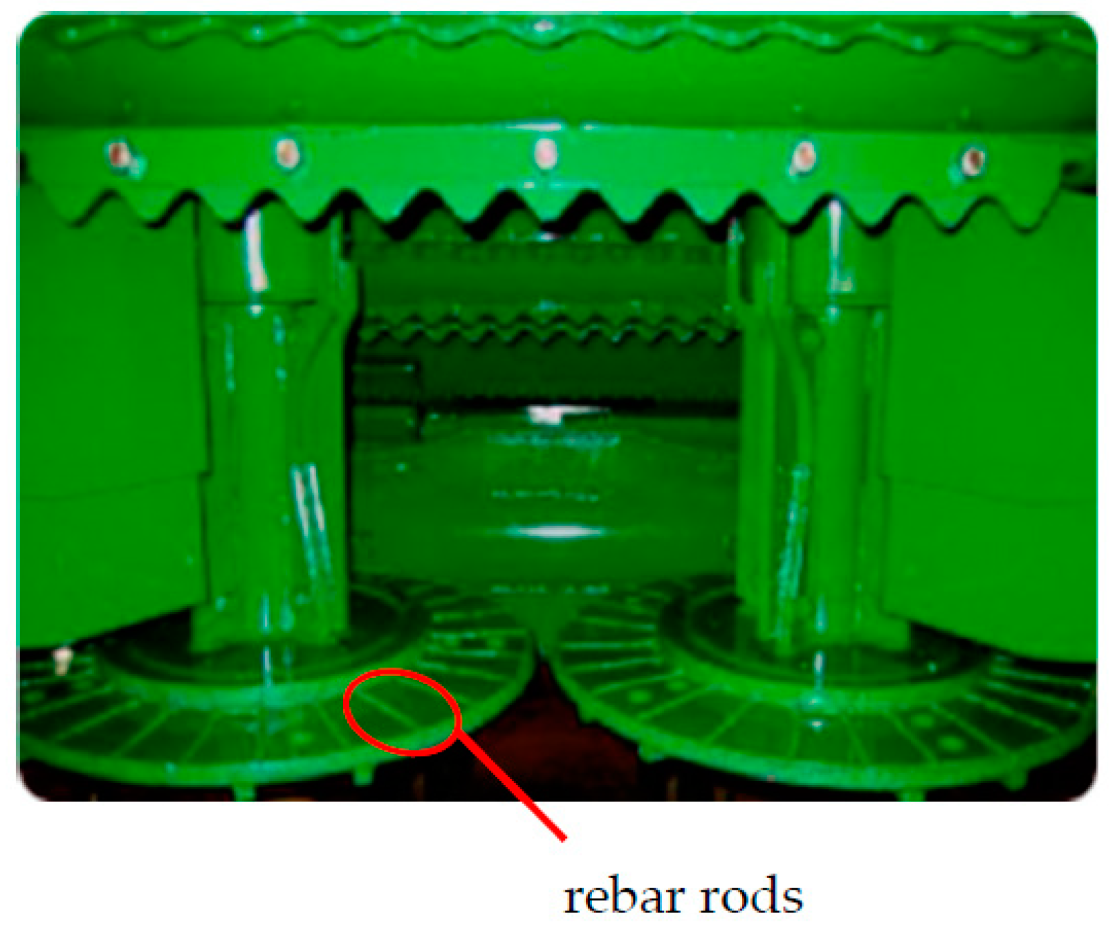
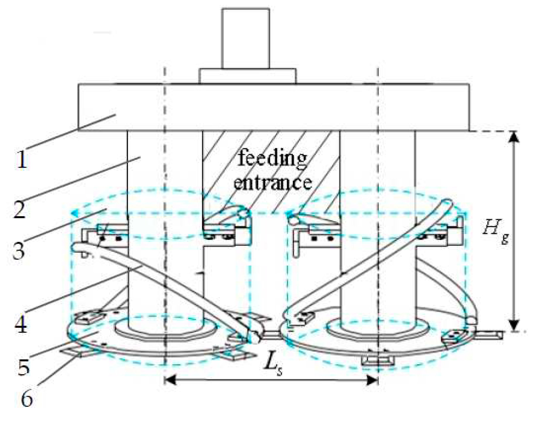
Basecutters of the HC-50N harvesters. 1 gear box 2 shafts sleeve 3 cylinder 4 spiral rebars rods 5 cutter discs 6 blades.
Figure 7.
Basecutters of the HC-50N harvesters. 1 gear box 2 shafts sleeve 3 cylinder 4 spiral rebars rods 5 cutter discs 6 blades.
Figure 8.
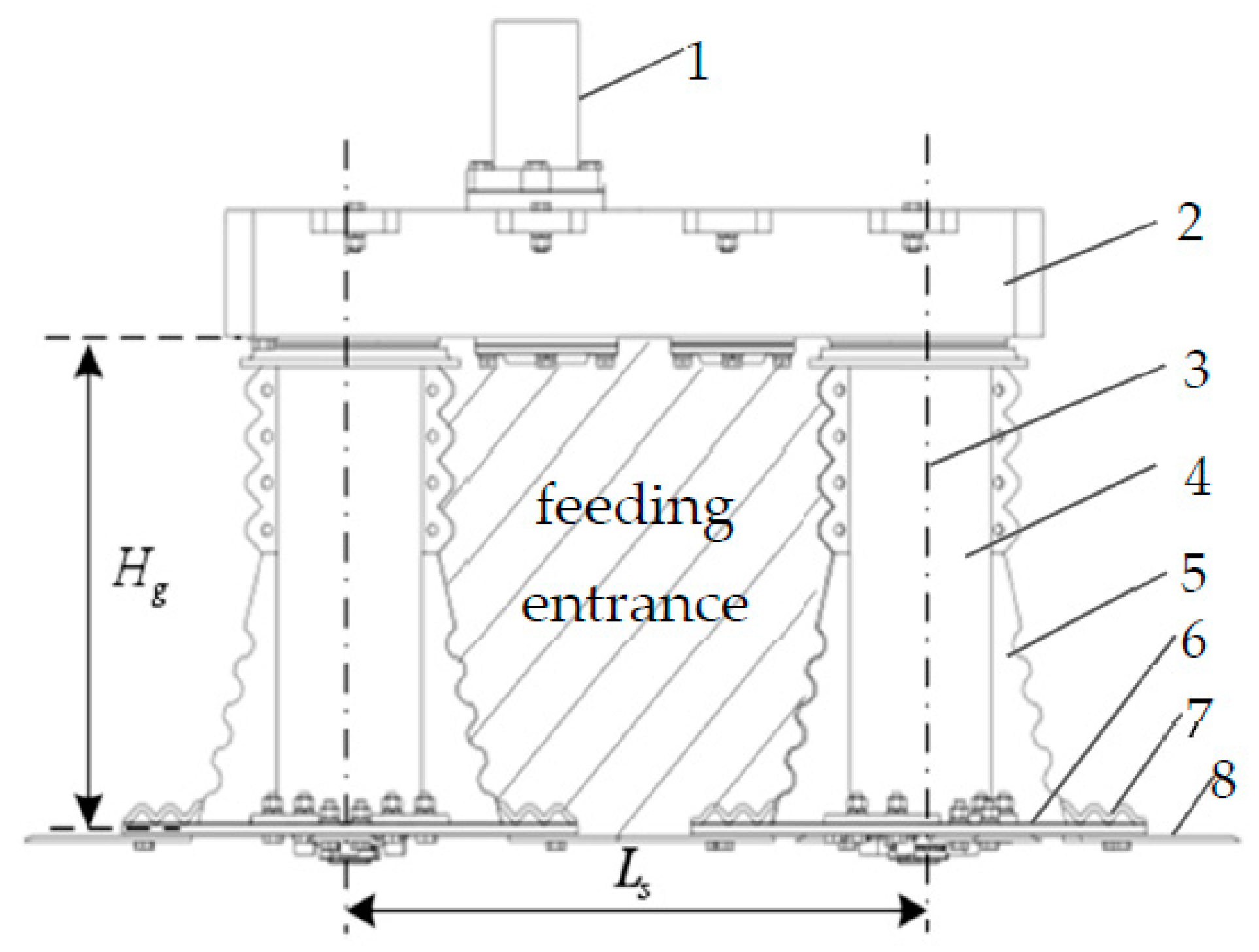
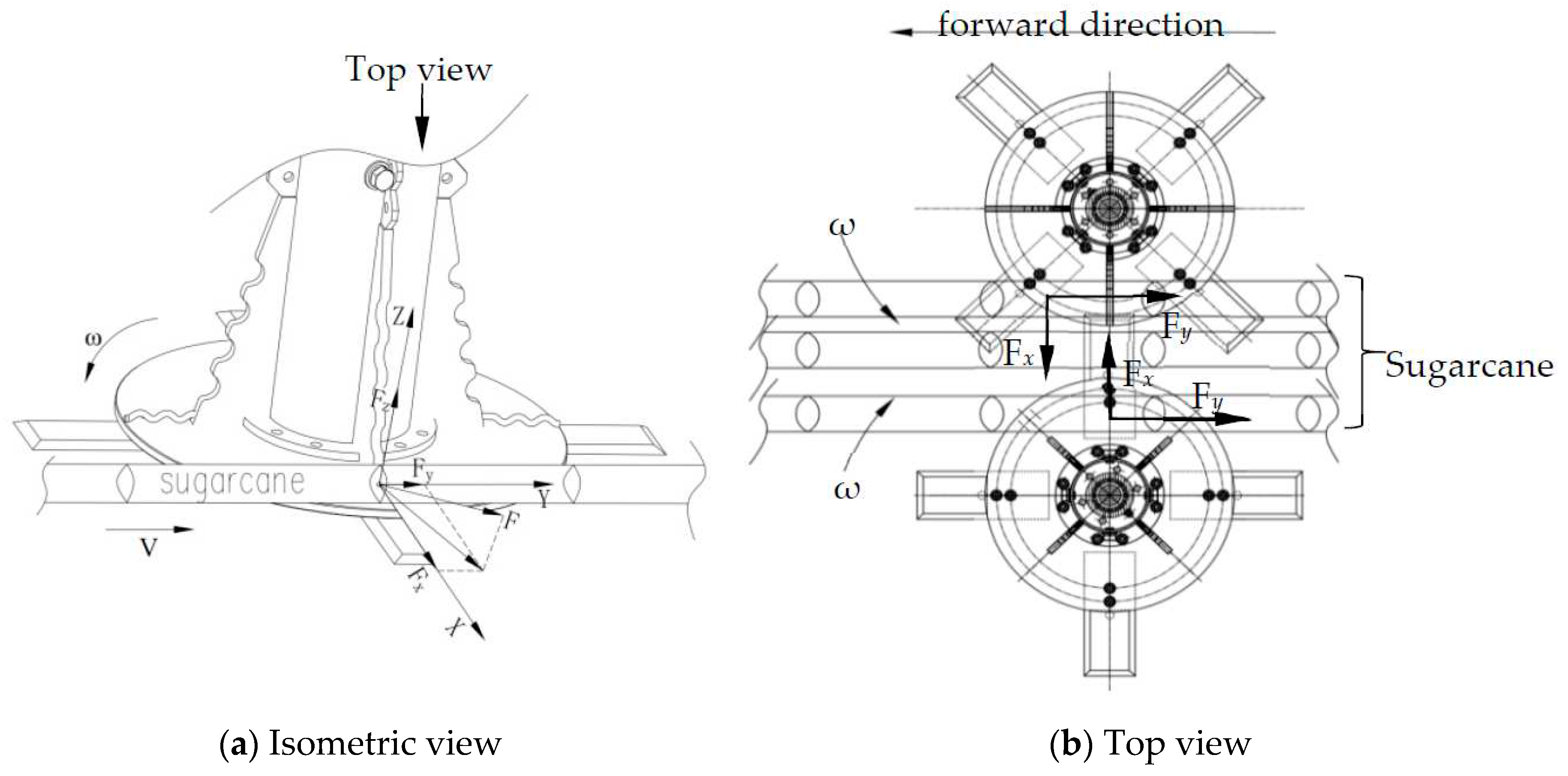
Feeding entrance of basecutter. 1 drive motor 2 gear box 3 shafts 4 shafts sleeve 5 toothed plates 6 cutter discs 7 small jagged bars 8 blades.
Figure 8.
Feeding entrance of basecutter. 1 drive motor 2 gear box 3 shafts 4 shafts sleeve 5 toothed plates 6 cutter discs 7 small jagged bars 8 blades.
Figure 9.
Analysis diagram of force applied on sugarcane stalk by a small jagged bar.
Figure 9.
Analysis diagram of force applied on sugarcane stalk by a small jagged bar.
Figure 10.
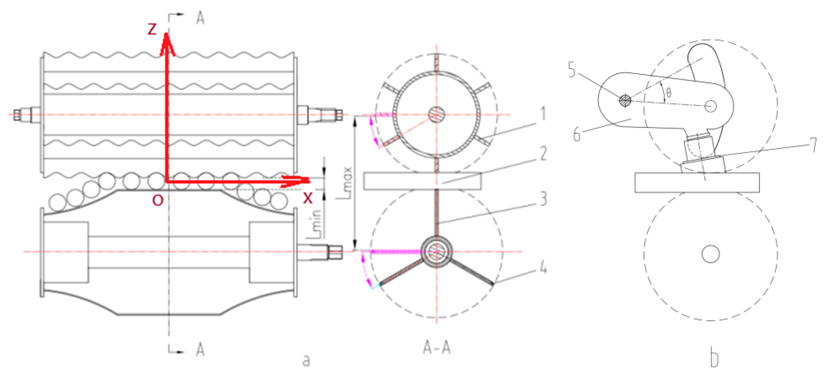
Schematic diagram of the feeding rollers. 1 blade of upper feeding roller 2 sugarcane 3 blade of lower feeding roller 4 rebar rod 5 shaft of swing arm 6 swing arm 7 rubber pad.
Figure 10.
Schematic diagram of the feeding rollers. 1 blade of upper feeding roller 2 sugarcane 3 blade of lower feeding roller 4 rebar rod 5 shaft of swing arm 6 swing arm 7 rubber pad.
Figure 11.
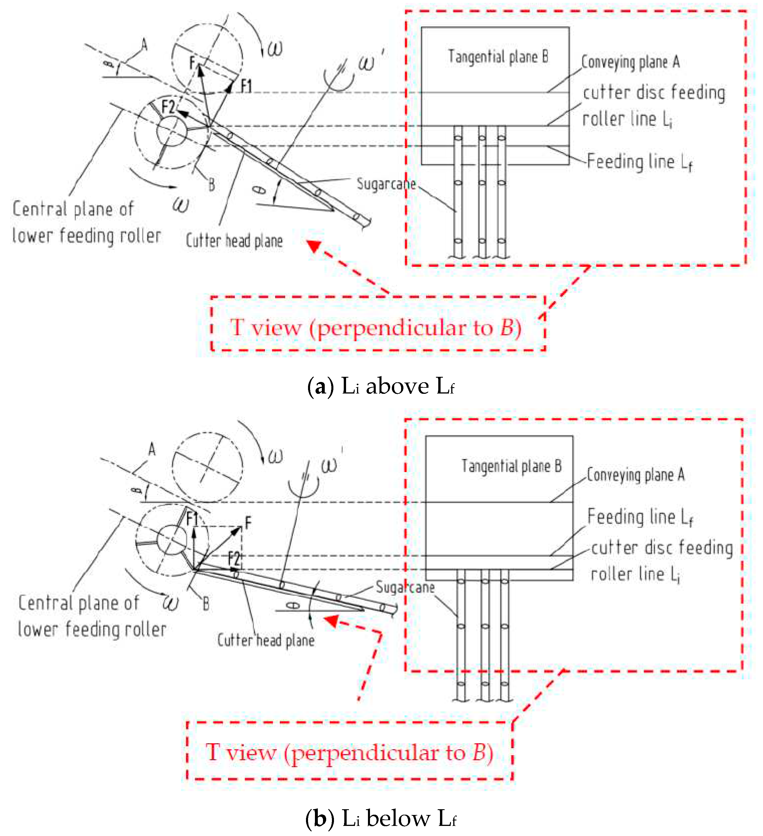
Analysis of the position relationship between the basecutter and the feeding roller.
Figure 11.
Analysis of the position relationship between the basecutter and the feeding roller.
Figure 12.
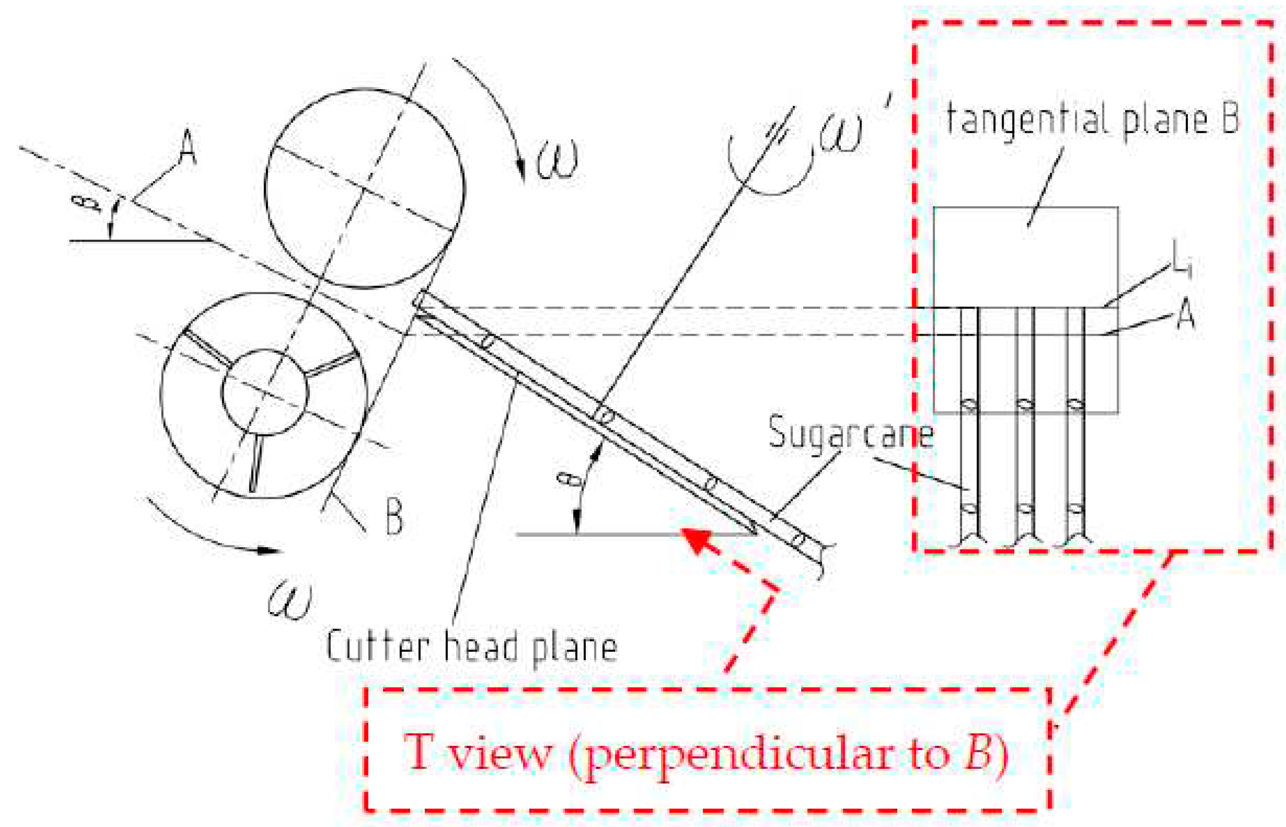
Position relationship between Li and A.
Figure 12.
Position relationship between Li and A.
Figure 13.
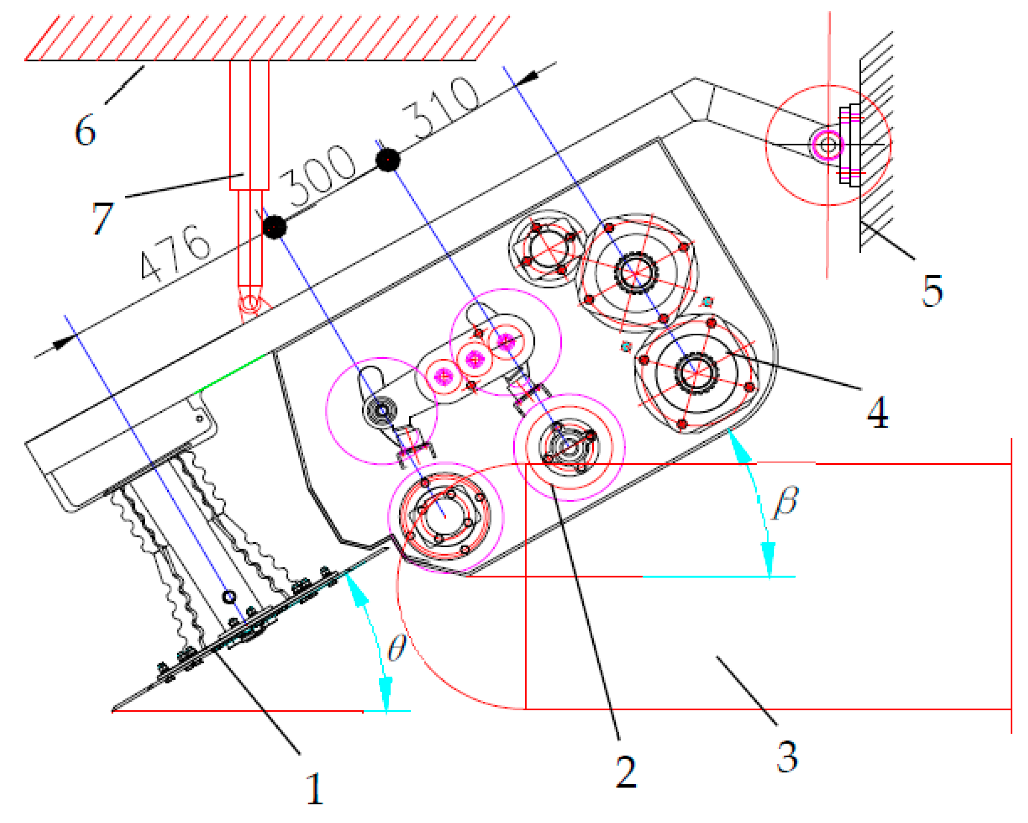
Relative installation angle between the basecutter and the roller device. 1 disc of basecutter 2 feeding/conveying roller train 3 crawler wheel 4 chopper 5 fixed frame 6 fixed frame 7 hydraulic cylinder.
Figure 13.
Relative installation angle between the basecutter and the roller device. 1 disc of basecutter 2 feeding/conveying roller train 3 crawler wheel 4 chopper 5 fixed frame 6 fixed frame 7 hydraulic cylinder.
Figure 14.
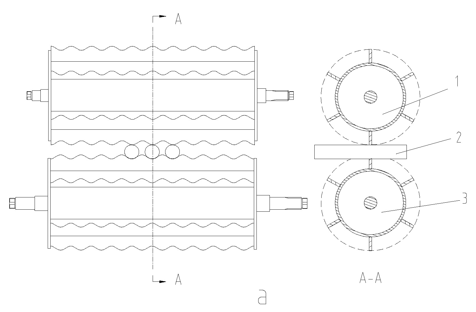
Structure and installation diagram of the conveying roller. 1 upper conveying roller 2 sugarcane 3 lower conveying roller.
Figure 14.
Structure and installation diagram of the conveying roller. 1 upper conveying roller 2 sugarcane 3 lower conveying roller.
Figure 15.
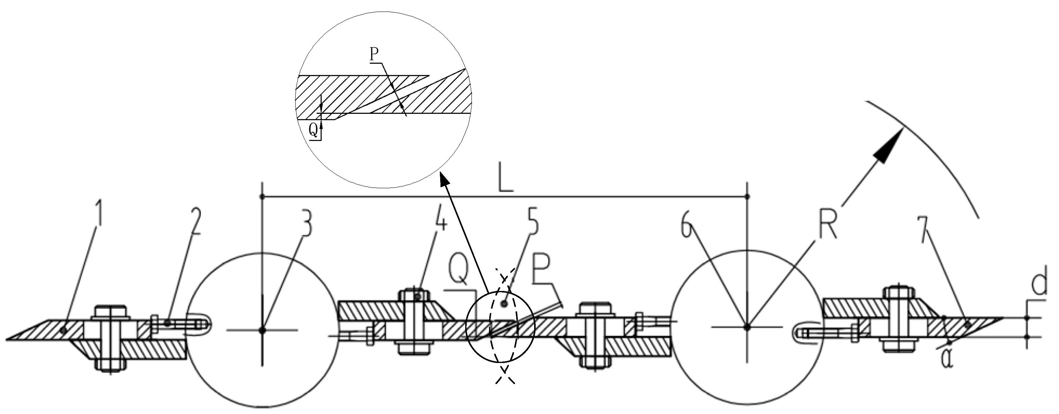
Structure of the chopper. 1 blade 2 adjusting bolt 3 upper chopper roller 4 fastening bolt 5 overlap area 6 lower chopper roller 7 blade.
Figure 15.
Structure of the chopper. 1 blade 2 adjusting bolt 3 upper chopper roller 4 fastening bolt 5 overlap area 6 lower chopper roller 7 blade.
Figure 16.
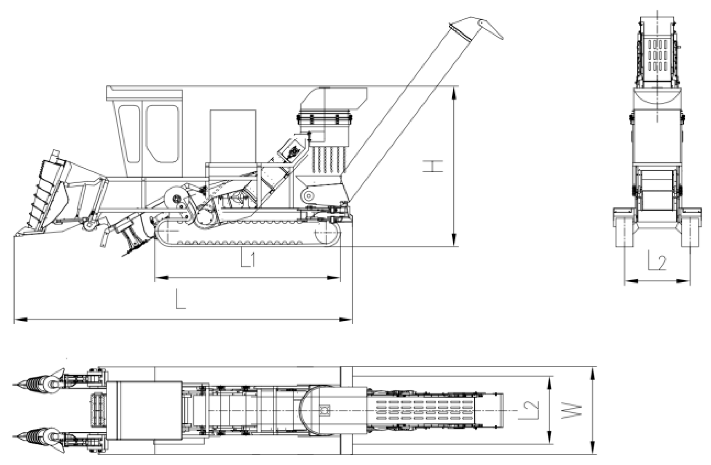
Design diagram of HN4GDL-91 sugarcane harvester.
Figure 16.
Design diagram of HN4GDL-91 sugarcane harvester.
Figure 17.
HN4GDL-91 sugarcane chopper harvester.
Figure 17.
HN4GDL-91 sugarcane chopper harvester.
Figure 18.
Layout of sugarcane clumps in field.
Figure 18.
Layout of sugarcane clumps in field.
Figure 19.
Impact trends and range chart of factors.
Figure 19.
Impact trends and range chart of factors.
Figure 20.
Impacts of A×D and B×D interactions on the performance indicators.
Figure 20.
Impacts of A×D and B×D interactions on the performance indicators.
Figure 21.
Results of the comparison test.
Figure 21.
Results of the comparison test.
Table 1.
Design parameters of the chopper centrally-mounted channel.
Table 1.
Design parameters of the chopper centrally-mounted channel.
| Parameters |
Values |
| Overall dimensions/mm |
1017 (L) × 776 (W) × 629 (H) |
| Upper feeding roller/mm |
L3=490, D1=232 |
| Lower feeding roller/mm |
L3=490, D2=252 |
| Conveying roller/mm |
L3=490, D3=232 |
| Chopper/mm |
L4=495, D4=266 |
| Center distance between the upper and lower rollers/mm |
H1=264.5 |
| Center distance between the feeding roller and conveying roller/mm |
L1=300 |
| Center distance between the conveying roller and chopper/mm |
L2=310 |
Table 2.
Parameters of HN4GDL-91 sugarcane harvester.
Table 2.
Parameters of HN4GDL-91 sugarcane harvester.
| Parameters |
Values |
| Overall size L×W×H (mm) |
6355×1780×2940 |
| Track length L1/track gauge L2 (mm) |
3480/1230 |
| Engine rated power (kW) |
91 |
| Displacement of the motor of knockdown roller (ml/r) |
160 |
| Displacement of the motor of basecutter (ml/r) |
80 |
| Displacement of the motor of feeding/conveying roller (ml/r) |
200 |
| Displacement of the motor of chopper (ml/r) |
200 |
| Displacement of the motor of billet conveying device (ml/r) |
125 |
Table 3.
Factor levels in the orthogonal test.
Table 3.
Factor levels in the orthogonal test.
| Level |
Factors |
| |
A: rotational speed of chopper (r/min) |
B: numbers of sugarcane stalk in a group (n) |
C: rotational speed of feeding/conveying rollers (r/min) |
D: ground speed
(m/s) |
| 1 |
230 |
5 |
150 |
slow (0.65) |
| 2 |
310 |
10 |
190 |
medium (1.09) |
| 3 |
390 |
15 |
230 |
fast (1.41) |
Table 4.
Results of orthogonal test.
Table 4.
Results of orthogonal test.
| No. |
A |
B |
A×B |
C |
A×C |
B×C |
D |
A×D |
B×D |
C×D |
Sz/%
|
Qw/kg/s |
Cdh/% |
| 1 |
1 |
1 |
1 |
1 |
1 |
1 |
1 |
1 |
1 |
1 |
9.00 |
2.30 |
89.90 |
| 2 |
1 |
1 |
1 |
1 |
2 |
2 |
2 |
2 |
2 |
2 |
1.76 |
6.02 |
87.21 |
| 3 |
1 |
1 |
1 |
1 |
3 |
3 |
3 |
3 |
3 |
3 |
6.30 |
5.65 |
90.66 |
| 4 |
1 |
2 |
2 |
2 |
1 |
1 |
2 |
2 |
2 |
3 |
2.55 |
9.50 |
86.29 |
| 5 |
1 |
2 |
2 |
2 |
2 |
2 |
3 |
3 |
3 |
1 |
2.95 |
9.17 |
86.48 |
| 6 |
1 |
2 |
2 |
2 |
3 |
3 |
1 |
1 |
1 |
2 |
3.30 |
7.61 |
87.57 |
| 7 |
1 |
3 |
3 |
3 |
1 |
1 |
3 |
3 |
3 |
2 |
2.18 |
18.77 |
78.71 |
| 8 |
1 |
3 |
3 |
3 |
2 |
2 |
1 |
1 |
1 |
3 |
1.84 |
9.54 |
92.78 |
| 9 |
1 |
3 |
3 |
3 |
3 |
3 |
2 |
2 |
2 |
1 |
2.57 |
9.40 |
95.39 |
| 10 |
2 |
1 |
2 |
3 |
1 |
2 |
1 |
3 |
3 |
1 |
3.44 |
3.12 |
95.24 |
| 11 |
2 |
1 |
2 |
3 |
2 |
3 |
2 |
1 |
1 |
2 |
6.11 |
5.41 |
92.20 |
| 12 |
2 |
1 |
2 |
3 |
3 |
1 |
3 |
2 |
2 |
3 |
8.32 |
6.00 |
90.24 |
| 13 |
2 |
2 |
3 |
1 |
1 |
2 |
2 |
1 |
1 |
3 |
3.81 |
9.41 |
96.10 |
| 14 |
2 |
2 |
3 |
1 |
2 |
3 |
3 |
2 |
2 |
1 |
2.12 |
9.85 |
95.99 |
| 15 |
2 |
2 |
3 |
1 |
3 |
1 |
1 |
3 |
3 |
2 |
1.92 |
6.69 |
96.45 |
| 16 |
2 |
3 |
1 |
2 |
1 |
2 |
3 |
2 |
2 |
2 |
2.00 |
2.79 |
95.53 |
| 17 |
2 |
3 |
1 |
2 |
2 |
3 |
1 |
3 |
3 |
3 |
1.80 |
9.44 |
94.76 |
| 18 |
2 |
3 |
1 |
2 |
3 |
1 |
2 |
1 |
1 |
1 |
1.51 |
13.67 |
96.91 |
| 19 |
3 |
1 |
3 |
2 |
1 |
3 |
1 |
2 |
2 |
1 |
5.57 |
3.00 |
91.01 |
| 20 |
3 |
1 |
3 |
2 |
2 |
1 |
2 |
3 |
3 |
2 |
1.64 |
5.24 |
94.30 |
| 21 |
3 |
1 |
3 |
2 |
3 |
2 |
3 |
1 |
1 |
3 |
4.34 |
7.42 |
94.95 |
| 22 |
3 |
2 |
1 |
3 |
1 |
3 |
2 |
3 |
3 |
3 |
2.01 |
12.04 |
96.02 |
| 23 |
3 |
2 |
1 |
3 |
2 |
1 |
3 |
1 |
1 |
1 |
1.21 |
13.09 |
97.65 |
| 24 |
3 |
2 |
1 |
3 |
3 |
2 |
1 |
2 |
2 |
2 |
2.19 |
6.76 |
97.26 |
| 25 |
3 |
3 |
2 |
1 |
1 |
3 |
3 |
1 |
1 |
2 |
1.37 |
13.34 |
96.43 |
| 26 |
3 |
3 |
2 |
1 |
2 |
1 |
1 |
2 |
2 |
3 |
2.41 |
7.02 |
97.83 |
| 27 |
3 |
3 |
2 |
1 |
3 |
2 |
2 |
3 |
3 |
1 |
2.07 |
13.52 |
97.36 |
Table 5.
Variance analysis of the orthogonal test.
Table 5.
Variance analysis of the orthogonal test.
| Performance indicator |
Sz, % |
Qw, kg/s |
Cdh,% |
| Source |
sig |
sig |
sig |
| A |
0.421 |
0.540 |
0.004** |
| B |
0.010* |
0.011* |
0.435 |
| A×B |
0.679 |
0.858 |
0.575 |
| C |
0.774 |
0.512 |
0.442 |
| A×C |
0.328 |
0.982 |
0.394 |
| B×C |
0.618 |
0.588 |
0.610 |
| D |
0.57 |
0.098 |
0.516 |
| A×D |
0.0** |
0.0** |
0.0** |
| B×D |
0.0** |
0.0** |
0.0 ** |
| C×D |
0.367 |
0.943 |
0.428 |
