1. Introduction
Since the first studies of Feldbaum [
1,
2], the Pontryagin’s Principle of Maximum [
3], etc. [
4,
5,
6,
7,
8,
9] the theory of the linear time-optimal control problem has been achieved maturity – the main theoretical issues have been thoroughly studied and answered. This historical evolution and facts are a solid foundation for the progress in this field [
10,
11,
12]. At the same time the applied aspects of this problem are always very interesting and attractive due to the fact it is great in many cases to achieve a transition from one to another system state in minimum time within the maximum utilization of the available system resources – control input's constraints as well as constraints on some state space variables, and all this being organized in a form of synthesis. As it is mentioned even in recent papers on the topic [
12] “there are plenty of researches trying to solve the problem analytically, while there is still no complete time optimal analytical solution for systems higher than second order.” The authors say also in [
12] „this paper has proposed a global time optimal control law for triple integrator with input saturation and full state constraints" while with regard to the obtained result it is said that “An analytical state feedback form control law has been synthesized based on the switching surfaces and curves”. In [
13], the dissertation [
14], as well as in next papers [
15,
16,
17,
18], some new properties of a class of linear time-optimal control problems are presented which are the basis of the author’s method for synthesis of the time-optimal control for a class of problems of any order without the need of describing the switching hyper-surfaces. The study [
19] shows the possibility for a practical application of the method. The so developed method covers a class of linear systems with real non-positive simple eigenvalues. One new property of the linear time-optimal control problem is discovered and proven here, which reveals the possibility for an expansion of the author’s method to the general case of real non-positive eigenvalues of the systems with no limitations with regard to the number of their eigenvalue multiplicity.
The paper is organized in the following way. In
Section 2 the new property of the linear time-optimal control problem is theoretically represented. In
Section 3 the solution of the chrestomathy example of the time-optimal control problem of a double integrator is obtained, first – in the classical way, and next – by application of the new property of the class of problems and the method [
14]. The conclusions are provided in
Section 3.
2. Formulation of the Problem and Solution
Let us consider the following linear time-optimal control problem of order , . The system is described by the equations (1) and let us suppose it is normal and with real non-positive eigenvalues. It should be mentioned that every one normal system with real eigenvalues could be transformed to such type of representation. The initial state at the moment of the system (1) is (2) and the target state at the moment represents the origin (5) of the system’s state space where is unspecified. The admissible control is a piecewise continuous function that takes its values from the range (3), which is continuous on the boundaries of the set of allowed values (3) and in the points of discontinuity we have (4).
The problem is to find an admissible control
which transfers the system (1) from its initial state (2) to the final state (5) in minimum time, i.e. minimizing the performance index (6). Let us refer to this problem as “Problem P(n)”.
The form of the equations of the system (1) allows introducing the linear sub-system (9) of order
with the state-space vector
(8) and scalar output
by the matrixes
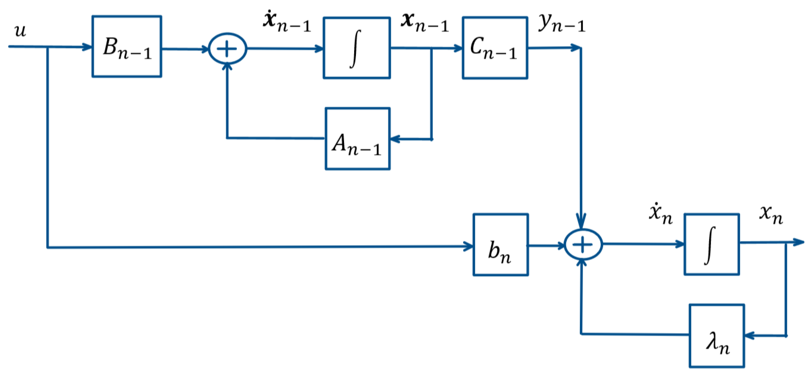
in the way (7). Thus the system (1) could be represented by (9) in the form (10) which is depicted also in
Figure 1. With regard to the sub-system (9) its initial state represents
(11) and the relation between the initial state (2) of the system (1) and the initial state (11) of the sub-system (9) represents (12).
Let as formulate now the following linear time-optimal control problem of order
which we shall call “Problem P(n-1)”. The system represents the equations (9).The initial state of the system (9) at the moment
is (11) and the target state at the moment
which is preliminary unspecified is the origin (13) of the (n-1)-dimensional state-space of the system (9). The admissible control
represents a piecewise continuous function that takes its values from the range (3), which is continuous on the boundaries of the set of allowed values (3) and in the points of discontinuity
we have (4). The Problem P(n-1) consists of synthesizing an admissible control
which transfers the system (9) from its initial state (11) to the final state (13) and minimizes the performance index (14).
Let us assume we have found the solution of Problem P(n-1) and denote by
the optimal time – the minimum time (15) of (14), by
the optimal control, and by
the optimal trajectory in the (n-1)-dimensional state-space of the system (9), which is described by (16) and (17).
Let us denote the scalar output of the system (9) in case it is the result of the optimal vector-function
as
. In that case
represents (18) and (19).
Let us define
(21) as an initial state of the n-th coordinate of the state-space vector
of the system (1) or (10) and consider the trajectory
in the n-dimensional state-space of Problem P(n) with initial state in the point
with coordinates (20) – (21)under the optimal control
of Problem P(n-1).
The vector-function
based on the representation of the system (1) in form (10) represents (22). The first (n-1) variables of the vector-function in (22) represent according to (16) the optimal vector-function
of Problem P(n-1), while in (22) with regard to the last n-th variable of
the function
represents the scalar output of the system (9) which is the result in this case of the optimal vector-function
. According to (18)
is
in this case. Thus we obtain (23) for
(22).
With regard to
(23) at the moment
we obtain (24). Then by substitution of
by (17) and
by (21) we obtain successively (25), (26), and (27).
Thus we obtain that the trajectory
in the n-dimensional state-space of the system (1) or (10) with initial point
(20) – (21) under the optimal control
of Problem P(n-1) ends at the moment
in the origin of the n-dimensional state-space of Problem P(n). Taking into account that the function
is the optimal control of Problem P(n-1) and thereby it represents a piecewise constant function with amplitude
and number of switchings maximum (n-2), i.e. with number of intervals of constancy maximum (n-1) [
7] (Chapter 2, §6, Theorem 2.11, p. 116), the trajectory
lies wholly on the switching hyper-surface of Problem P(n).
Let us now consider the trajectory
(28) in the n-dimensional state-space of Problem P(n) with initial point representing the initial state
(2) or (12) of Problem P(n) under the optimal control
of Problem P(n-1). The first (n-1) variables of the vector-function in (28) represent according to (16) the optimal vector-function
of Problem P(n-1). With regard to the last variable of
in (28) the function
is the scalar output of the system (9) which is the result of the optimal vector-function
. According to (18) the function
represents
in this case. Thus we obtain (29) for
(28).
Let us consider now the difference between the two vector-functions
(29) and
(23). We obtain successively (30) and (31).
We could state with regard to the last n-th coordinate of (31) for :
If , then the initial state (2) or (12) of Problem P(n) coincides with the point with coordinates (20) – (21). We have already shown that is a point of the switching hyper-surface of Problem P(n) and the trajectory with initial point under the optimal control of Problem P(n-1) lies wholly on the switching hyper-surface of Problem P(n) and ends at the moment in the origin of the n-dimensional state-space of the system (1) or (10) of Problem P(n);
If , then the initial state (2) or (12) of Problem P(n) does not coincide with the point with coordinates (20) – (21). The expression for does not change it sign and is not equal to zero because of the fact is a finite time. Thus the trajectory with initial state (2) or (12) of Problem P(n) under the optimal control of Problem P(n-1) lies entirely above or below the switching hyper-surface of Problem P(n) nowhere intersecting it and ends at the moment in a point of the coordinate axis different from zero.
Thus, the following theorem has been proven.
Theorem 1.
The trajectory of the system (1) or (10) with initial point in (2) under the optimal controlof Problem P(n-1) lies wholly on the switching hyper-surface of Problem P(n) and ends at the momentin the origin of the n-dimensional state-space of the system (1) or (10) of Problem P(n) or lies entirely above or below the switching hyper-surface of Problem P(n) nowhere intersecting it and ends at the momentin a point of the coordinate axisdifferent from zero.
3. Example
Let us consider the following example of synthesizing the time-optimal control of a double integrator [
7] (§ 3. Example. The problem of synthesis, p. 38), [
10] (Chapter 7, Problem 7.1, p. 150), [
11], which has already become a chrestomathy example and as such even found a place in online optimal control courses on world platforms with video content [
20,
21,
22,
23] (it should be noted that these online resources are often volatile and unavailable after some time). First, we will show namely this classical synthesis, and after that – the synthesis based on the expansion of the author’s method [
14] by the new property, which allows synthesizing without the need of describing the switching hyper-surfaces and applicable now in case of multiple number of system’s eigenvalues (the example here is with regard to double zero).
The system is described by the variables
(position) and
(velocity) and represents (32). Let the constraints of the admissible control
(3), (4), be (33).
3.1. Classical Synthesis
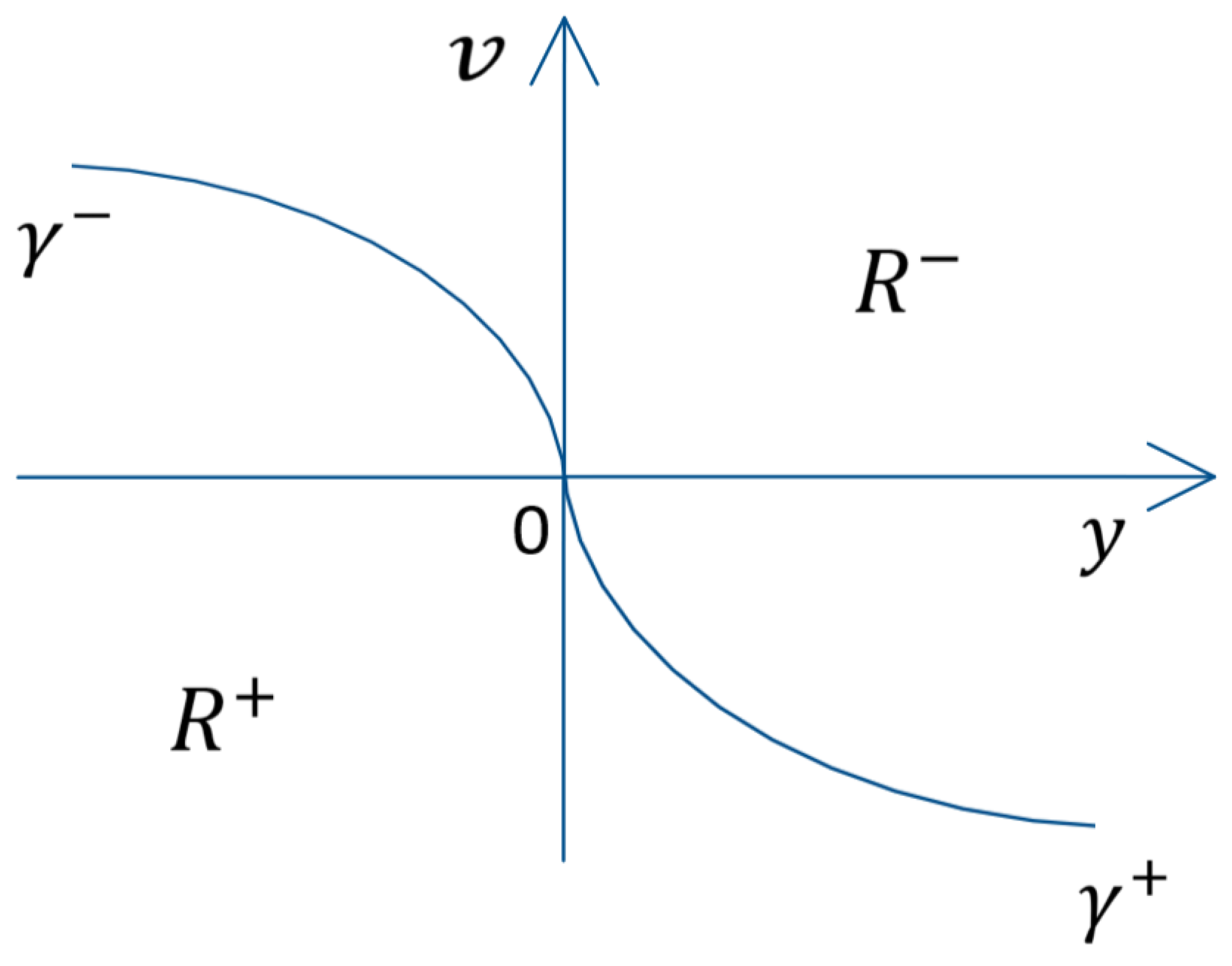
The switching curve
in the phase plane
is described by (34). The two pieces
and
of the switching curve
are the parts of the parabolas representing the phase trajectories going through the origin of the phase plane in case of constant control
or
respectively. The two areas
and
(35) in the phase plane, below and above the switching curve
(34) respectively, represent the areas where the optimal control takes a value
with regard to the points of
and
with regard to the points of
. The areas
and
as well as the parts
and
of
are shown in
Figure 2. The time-optimal control is synthesized in form (36). After substitution of
and
by (35) as well as
and
by (34) in (36) the synthesized optimal control becomes (37).
3.2. Synthesis Based on the New Property and the Method [14]
Let us now turn to the synthesis based on the method developed in [
14] and widen by the new property. One of the main properties which form the foundations of this method is with regard to the trajectory in the state-space of one time-optimal control problem of higher order generated by the control representing the solution of the problem of the lower order where all the time-optimal control problems of descending order are generated by the problem of the utmost order and form a class of problems. As we have shown here the new property represents an expansion covering the general case of systems with real eigenvalues, no matter of the number of eigenvalue multiplicity. The example here considers a system of order two, so the synthesis is directly based on the solution of the problem of order one, which allows expressing also analytically the solution of the initial problem.
Step 1. First we make a suitable change of variables in the way (38) and obtain a representation by
which could be done also by the matrix
(39) – (40) in the way (41). Thus we obtain (43) and (44) from the initial system (32) through its matrix representation (42). The system (44) is now in the form (1). Then (44) in form (10) is represented as (45) – (46) (as (1) in form (10)). The sub-system of (45) – (46) is (47) or (48).
Step 2. Solving Problem P(1). The eigenvalue of
is 0. The optimal control of Problem P(1),
for
is (49) – (50) [
14] (pp. 50-52).
Step 3. Calculating the value of the variable
. The variable
is defined in [
14] (pp. 39-40), [
16] (p. 320), [
17] (p. 41) and in case of expanding the class of time-optimal control problems it represents here at
the n-th coordinate of the vector
(29) at the moment
In case
the variable
represents (52). With regard to the system (47) or (48) of Problem P(1) the variable
(52) becomes (53) and after simplifying – (55).
Step 4. Applying the theorem for synthesizing the optimal function in the initial state [
14] (Theorem 3.2, pp. 40-43), [
16] (Theorem 3, p. 320), [
17] (Theorem 3, p. 41). According to this theorem and its corollaries the time-optimal control in the initial state of Problem P(2) represents (56).
The variable
, respectively
in (56), is a term introduced in [
14] (p. 38), [
16] (pp. 319-320) which defines the relation of the points of the axis
of the state-space of the system of Problem P(k) from the considered class of problems to the switching hyper-surface of the same Problem P(k). The value of the variable
is determined by a procedure called “axes initialization” [
14] (Chapter 3,
Section 3.3, pp. 60-88), [
17] (pp. 41-45).
With regard to the example (57). This means that all the points of the negative semi-axis are above the switching curve of Problem P(2) and the optimal control value for them is while all the points of the positive semi-axis are below the switching curve of Problem P(2) and the optimal control value for them is .
Thus with regard to the initial state
based on (56) after substitution of
by (55) and
(57) we obtain (58). So, the synthesized optimal function with regard to a state
is (59). Taking into account
according to (46), (59) becomes (60).
It is easy seen, taking into account the relation (38) or (41) between and the analytical expression of the synthesized here optimal control (60) is identical with the expression obtained by the classical synthesis (37).
3.3. Simulation Results
Let us employ for illustration two initial states (61) и (62). The corresponding initial states in the state-space
of the system (44) are (63) and (64). At Step 2 with regard to (63) we obtain according to (49) – (50) the result (65).At Step 3 according to (53) with regard to
we obtain (66). Thus, at Step 4 according to (56) and (57) the result for the time-optimal control in the initial state (63)
is (67). Analogically, with regard to the initial state (64) at Step 2 we obtain again (65), but with regard to
the result is (68), which leads to
(69).
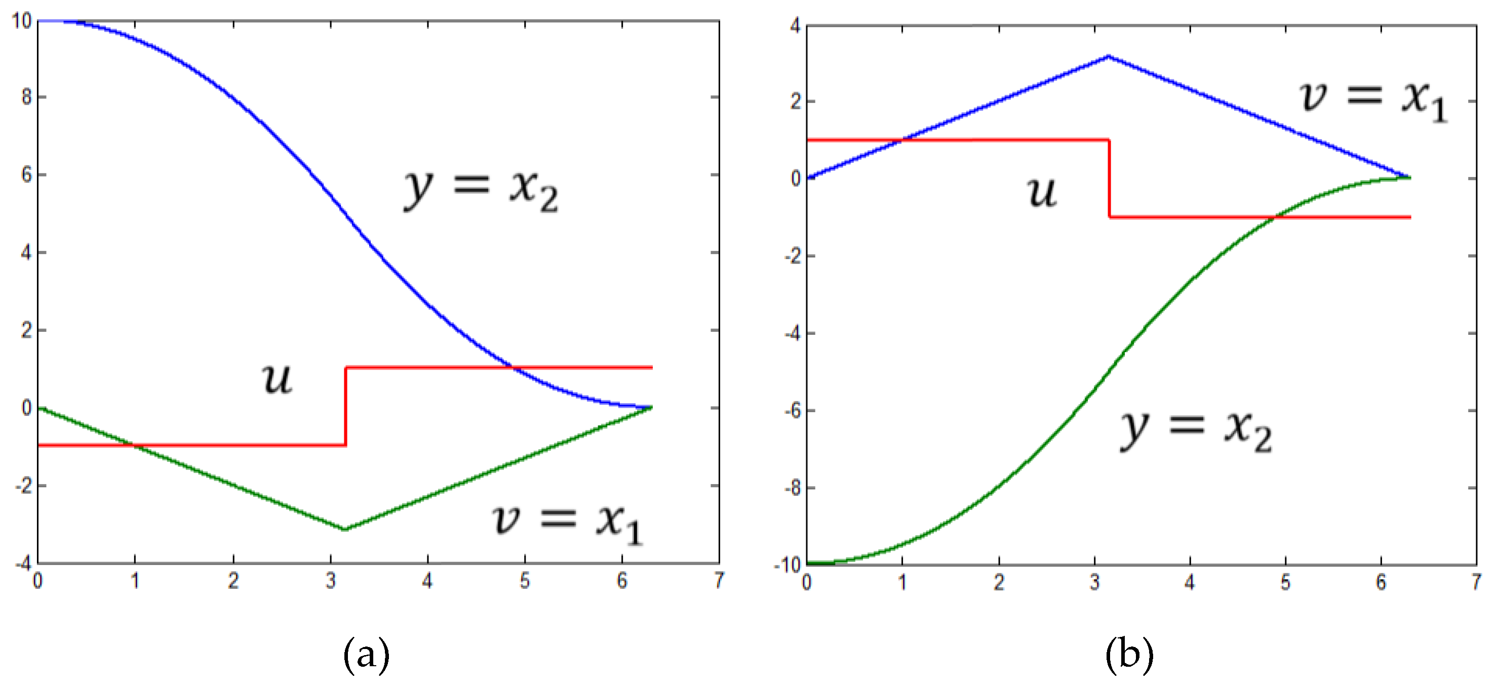
Figure 3 shows the near time-optimal processes with an accuracy
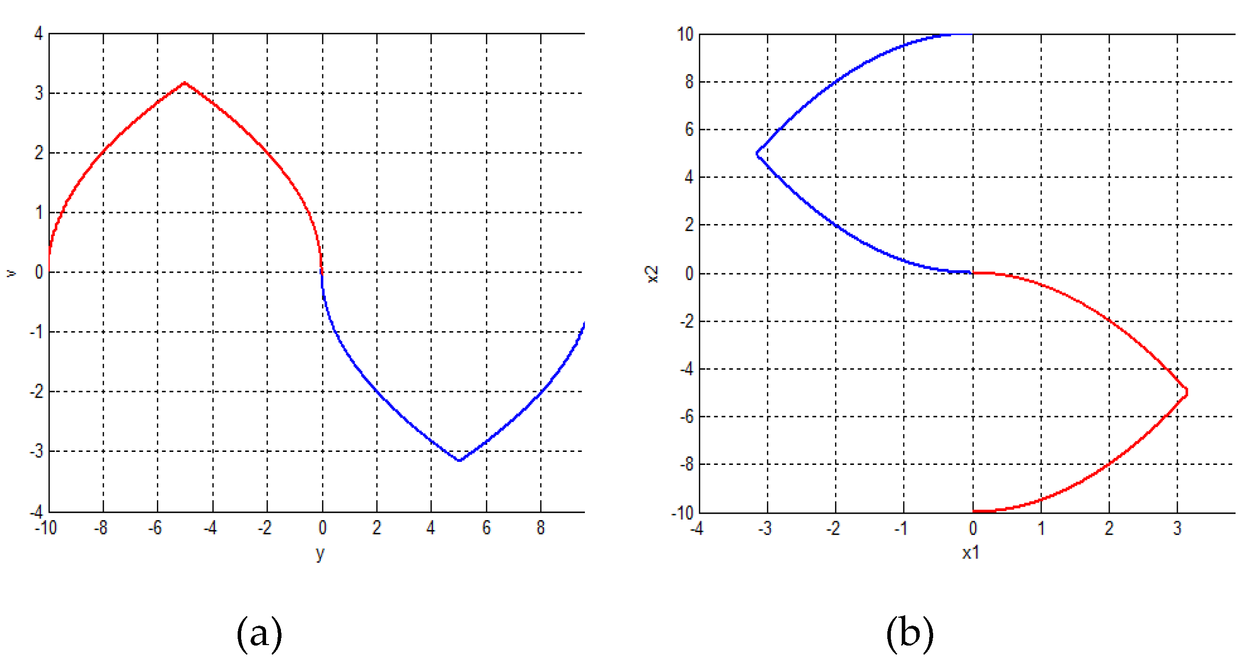
with regard to the considered initial states while the trajectories in the phase plane
of the system (32) are shown in
Figure 4a. The blue phase trajectory is with regard to the initial state
. The red one is with regard to the initial state
The near time-optimal trajectories with regard to the corresponding initial states in the state-space
of (44)
and
are represented in the phase plane
of (44) in
Figure 4b. The blue trajectory in with regard to the state
, but the red one is with regard to
The conversion of the trajectories shown in
Figure 4b by the relation (41) returns the identical result shown in
Figure 4a.


