Submitted:
14 June 2023
Posted:
15 June 2023
You are already at the latest version
Abstract
Keywords:
1. Introduction
- 1)
- Crucially, the outputs of renewable energies are considerably unstable depending on climate change. As mentioned, this defect implies that large storage batteries must be introduced, which are expensive. Moreover, if large amounts of renewable energies are introduced, the unstable outputs inevitably result in instability in the existing power system.
- 2)
- DNE 21+ calculated the potential, including nuclear power generation. However, we cannot forget the Fukushima nuclear accident in Japan in 2011.
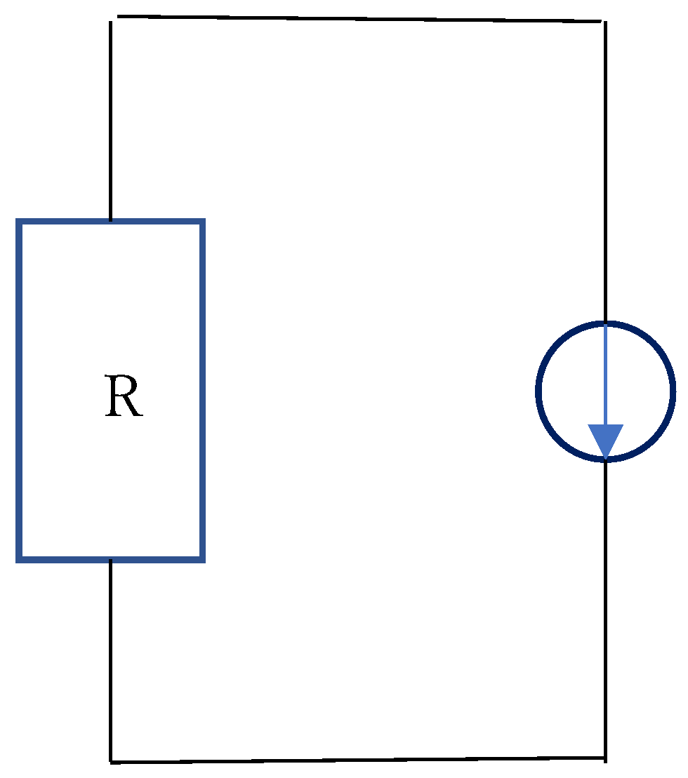
2. Review of a voltage source and current source
3. Principle
4. Method
4.1. Instruction of this section
- 1)
- The necessity to input a voltage in the current source when it charges a super-condenser
- 2)
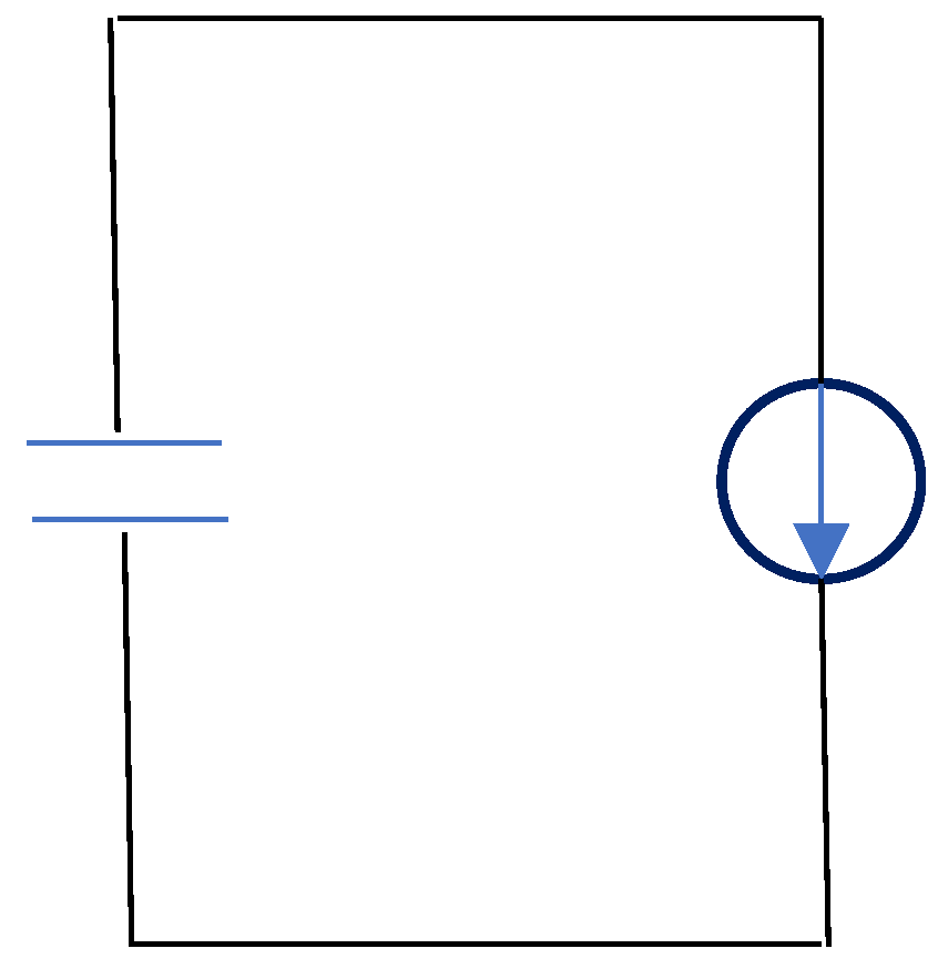
- The necessity to input a voltage in the current source when it generates current to load
4.2. Main body of this section
- The impedance of the current source is relatively high.
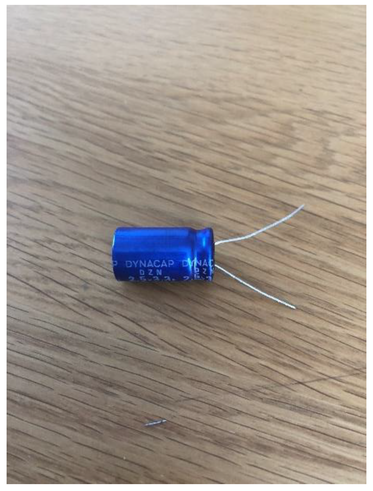
- The input impedance of the super-condenser is considerably low.
- (The first stage)
- (The second stage)
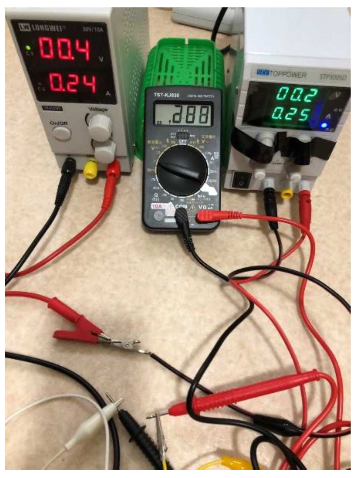
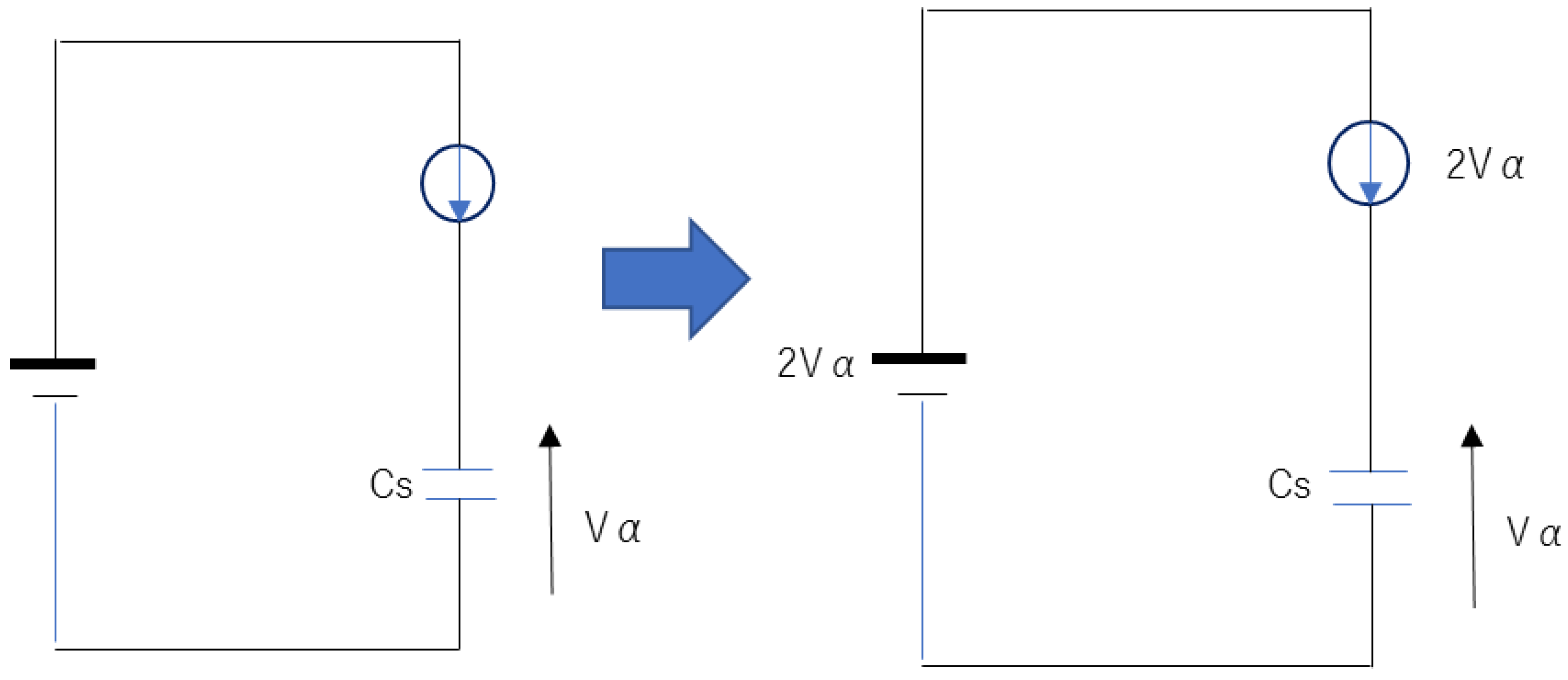
- After setting the voltage of the voltage source of the cv mode, a current is supplied by the current source of the cc mode.
- The voltage/current of the cc mode of the current source varies (0.0/0.0, respectively).
- Resultantly, more energy is given to the super-condenser:
- 4.
- The cc mode of the current source changes to the cv mode.
- 5.
- The cv mode of the current source is reset to the cc mode to proceed to the third stage.
- (The third stage)
5. Result
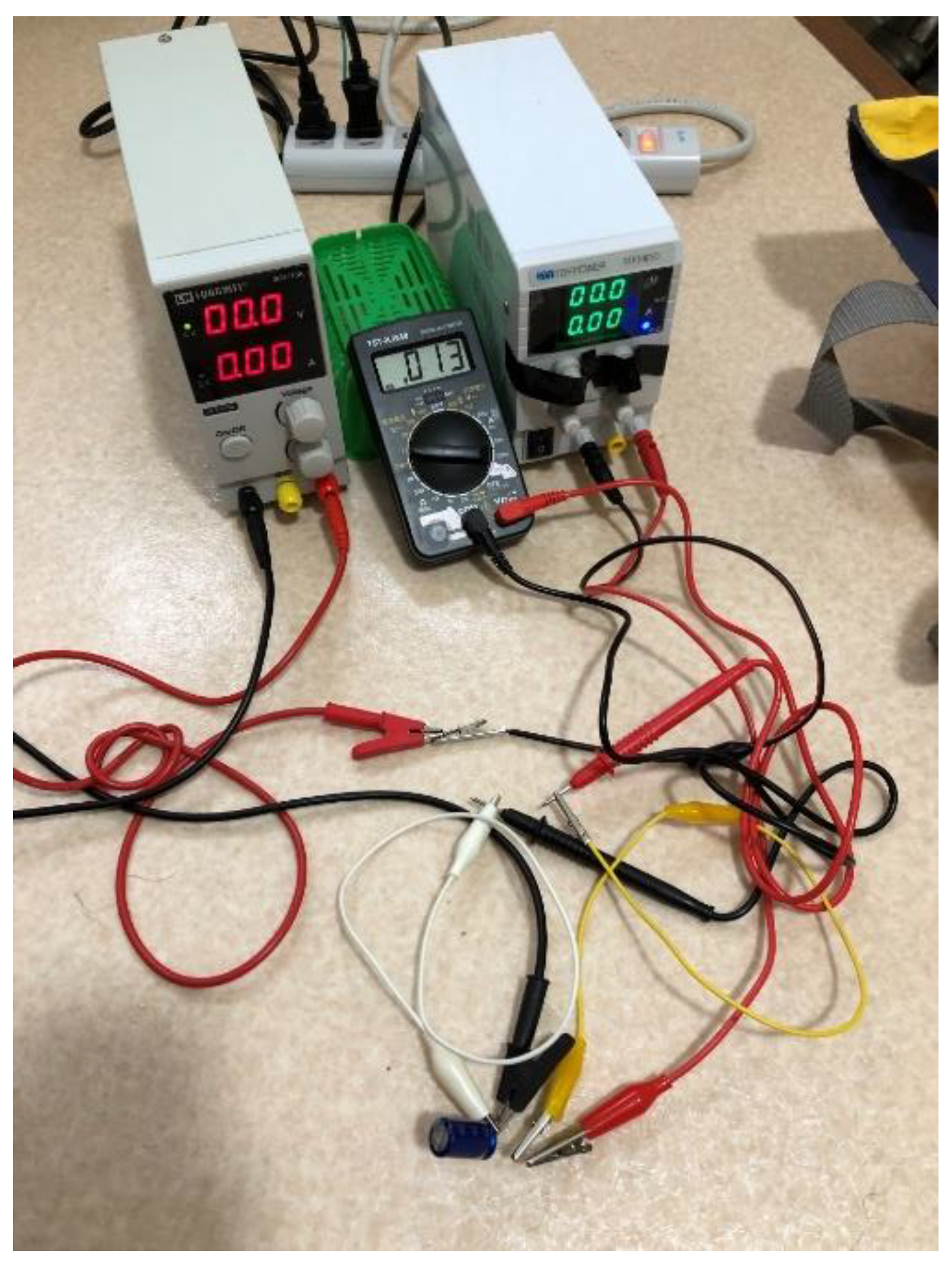
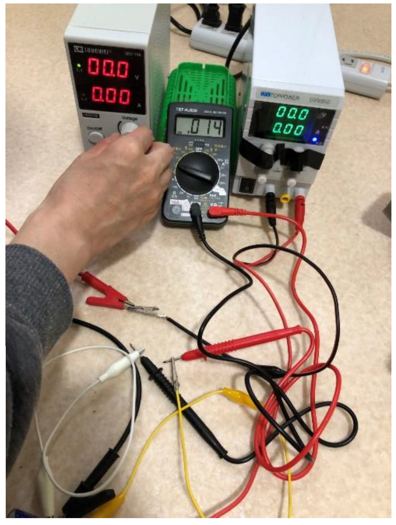
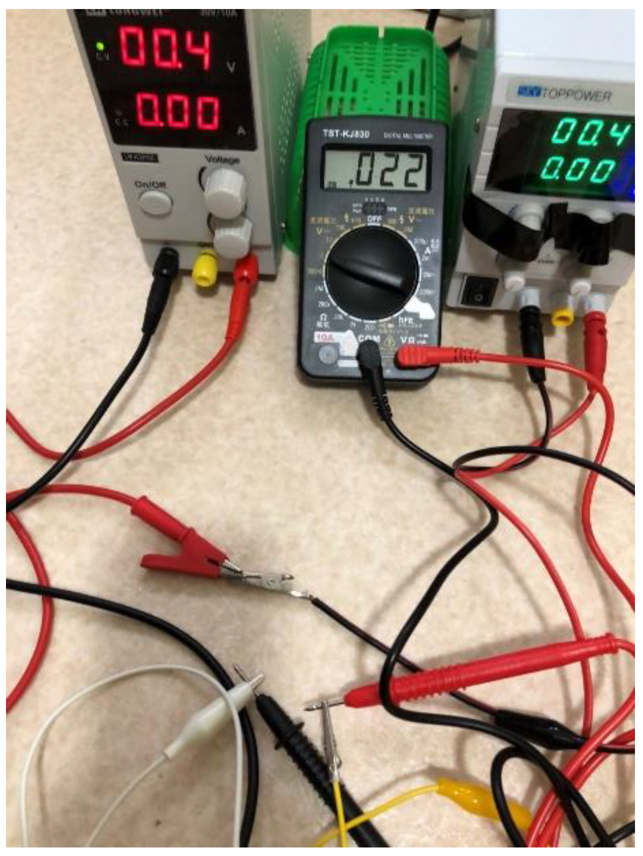
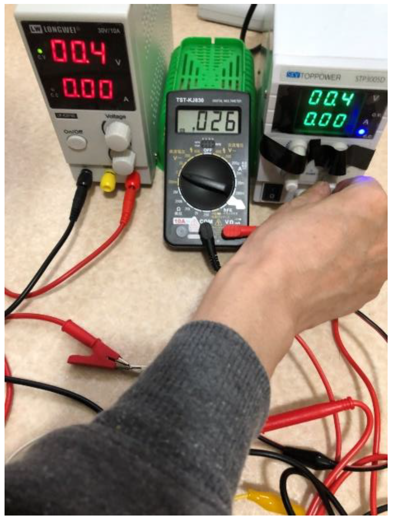
6. Discussion
6.1. Feed-back to operate the power supplies
6.2. The reduction of the cost of storage battery when operating our system
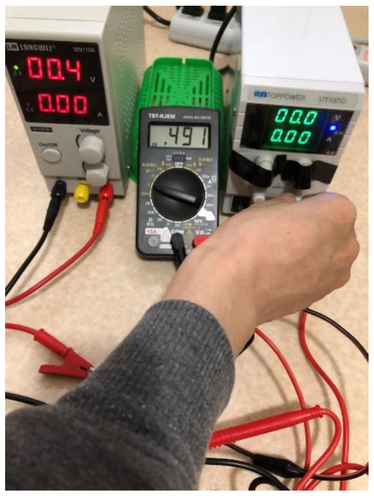
6.3. The evidence that the input voltage in the current source had been zero
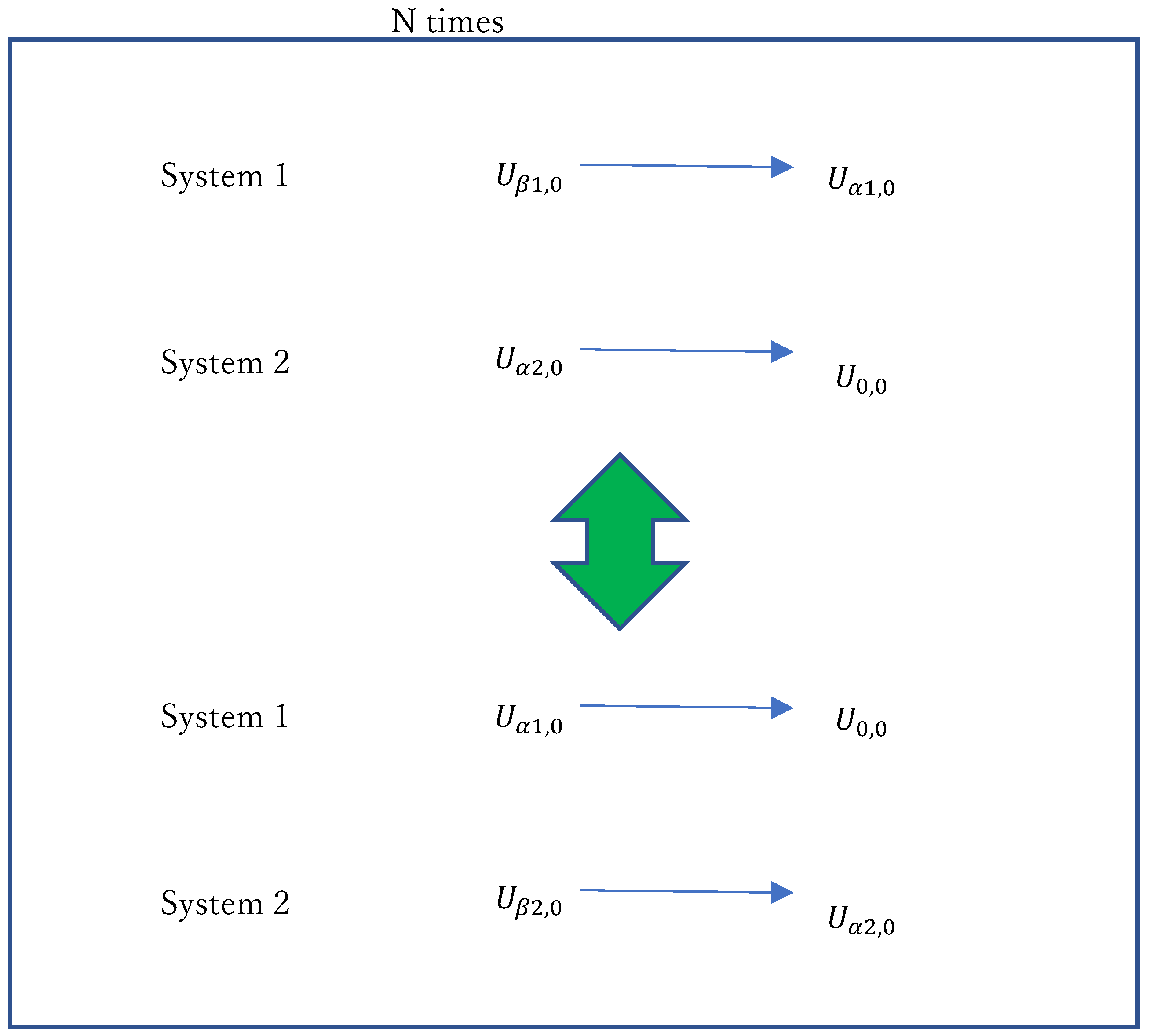
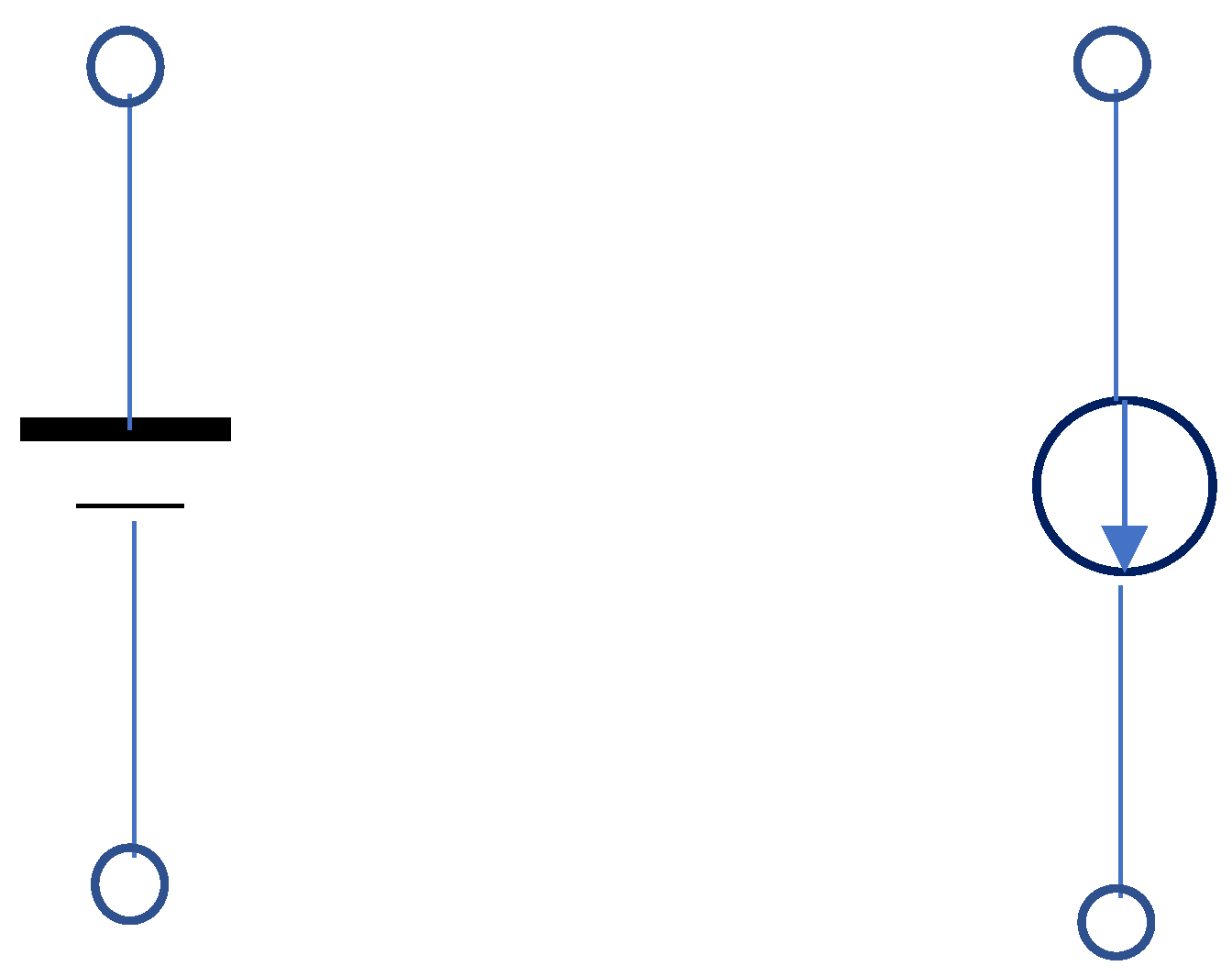
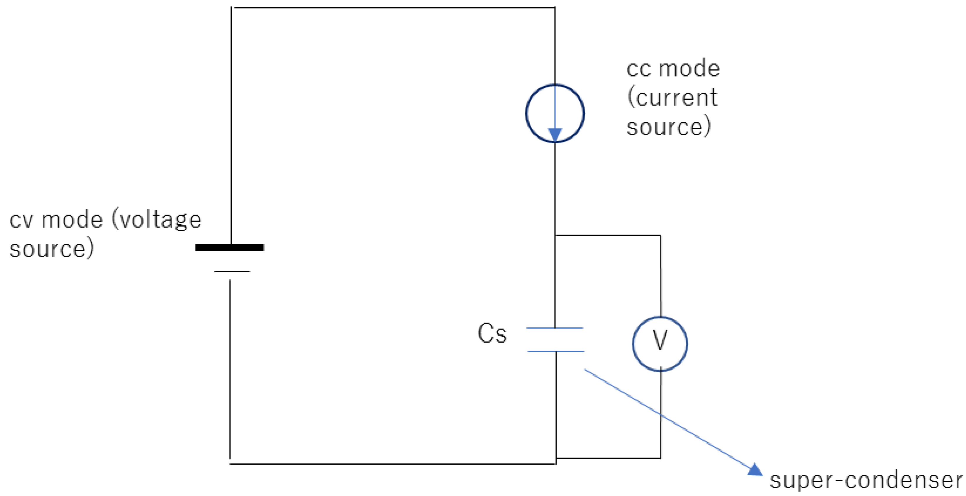
- Among the two stabilized power supplies, one is set to the cv mode as the voltage source and the other is set to the cc mode as the current source.
- The initial voltage from the voltage source, Vα, is applied.
- A current is applied from the cc mode of the current source to the system.
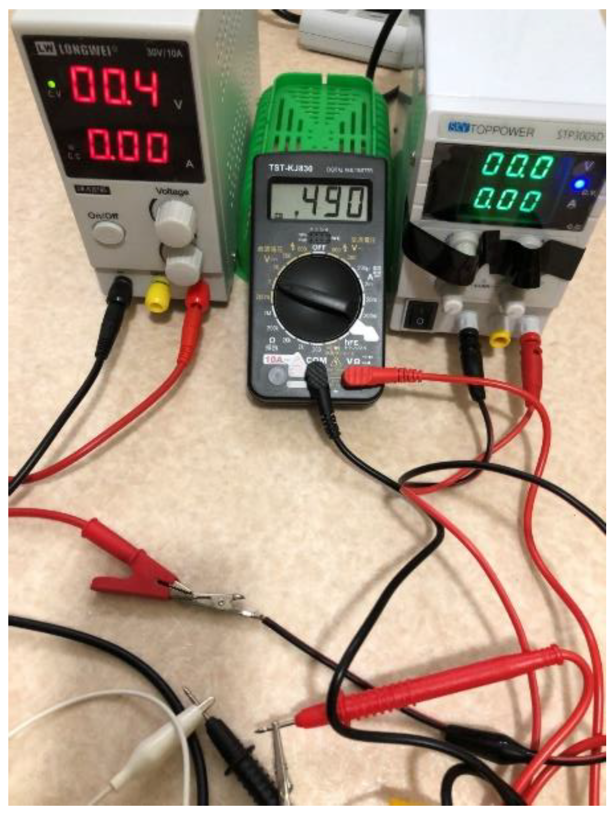
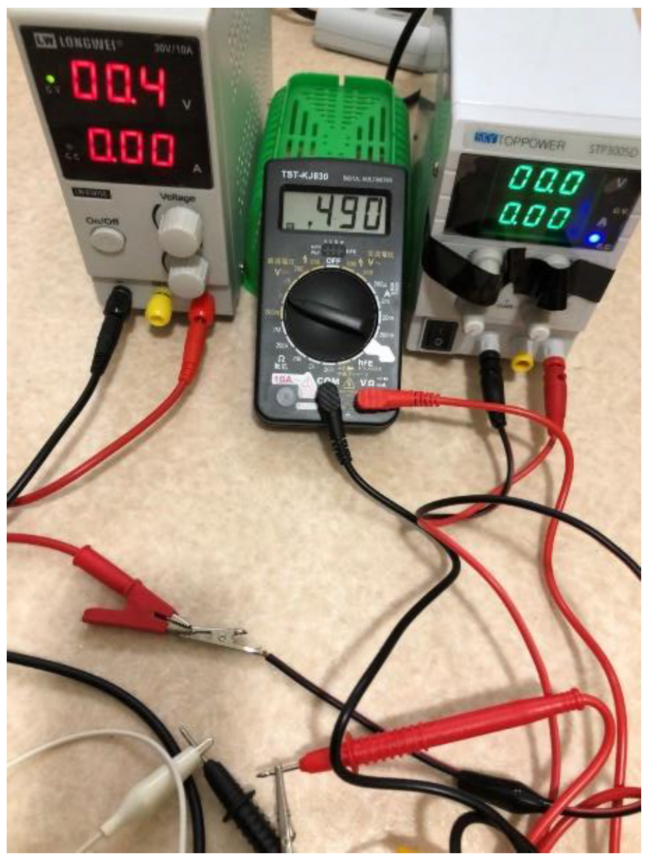
- The voltage/current of the current source in the cc mode varies (0.0/0.0, respectively).
- Simultaneously, the charging of the super-condenser is achieved.
- The cc mode of the current source automatically changes to the cv mode.
- The cv mode of the current source is reset to the cc mode to proceed to the next stage.
6.4. Discussion of the conversion of energy
6.5. Significance of this paper
7. Conclusions
Acknowledgments
Additional information
References
- P. Anand et al. Insights Reg.Dev. 2022, 4, 96–109.
- A. Tyo et al, Entrep. Sustain. 2019, 7, 1514–1524.
- L. EI Iyaouy et al. Insights Reg. Dev. 2019, 1, 259–271.
- M.R. Chehabeddine et al. Insights Reg. Dev. 2022, 4, 22–40.
- H. Obane et al. Renewable Energy 2021, 160, 842–851.
- O. Sabishchenko et al. Energies 2020, 13.
- M. Wierzbowski et al. Renew. Sustain. Energy Rev. 2017, 74, 51–70.
- C.-W. Wang et al, Energies 2020, 13, 2629.
- T. Radavicius et al, Insights Reg. Dev. 2021, 3, 10–30.
- K. Akimoto et al. Energy and Climate Change 2021, 2, 100057.
| Voltage [V] | Current [A] | |
|---|---|---|
| cv mode | Vα | Iα from cc mode |
| cc mode | Vα from cv mode | Iα |
| Voltage [V] | Current [A] | |
|---|---|---|
| cv mode | Vα | from cc mode |
| cc mode | from cv mode |
| Voltage [V] | Current [A] | |
|---|---|---|
| cv mode | Vα | 0 |
| cc mode → cv mode | 0 | 0 |
Disclaimer/Publisher’s Note: The statements, opinions and data contained in all publications are solely those of the individual author(s) and contributor(s) and not of MDPI and/or the editor(s). MDPI and/or the editor(s) disclaim responsibility for any injury to people or property resulting from any ideas, methods, instructions or products referred to in the content. |
© 2023 by the author. Licensee MDPI, Basel, Switzerland. This article is an open access article distributed under the terms and conditions of the Creative Commons Attribution (CC BY) license (https://creativecommons.org/licenses/by/4.0/).


