Preprint
Article

Finite Element Analysis (FEA) Of a Premaxillary Device: A New Type of Subperiosteal Implant to Treat Severe Atrophy of the Maxilla

Altmetrics

Downloads

218

Views

110

Comments

0

A peer-reviewed article of this preprint also exists.

Submitted:

15 June 2023

Posted:

15 June 2023

You are already at the latest version

Alerts
Abstract
Extreme atrophy of the maxilla poses still challenging for the clinicians. Some of the techniques used could be complex, risky, expensive, time consuming and should be performed, preferably, only by skilled surgeons. Most the commonly used techniques have been reported to have very high success percentages; however, sometimes complications may occur. In this regard, Premaxillary Device (PD) is a technique that has been devised to render more simple the reconstruction of extremely atrophic maxilla, trying to avoid more complicated and risky surgical procedures. Finite Element Analysis (FEA) allows evaluation of several differen aspects of dental implant biomechanics. Our results showed that the use of PD allows an optimal distribution of the stresses on the basal bone, avoiding tension peaks that could determine bone resorption or, even, implant failure. ANSYS has been used to perform this type of localized finite element analysis; with this type of analysis, it was possible to analyze the peri-crestal area of the plant more precisely and the PD through a more accurate reconstruction of the mesh element, which allowed us to mathematically solve the FEA solution. A most favorable biomechanical behavior has been found for the materials such as titanium alloys and reduce stress levels for bone, implants, screws, and abutments. Moreover, the stress values did not exceed bone strength limits for basal bone and titanium alloy. In conclusion, from a biomechanical point of view, PD could be considered a viable alternative for rehabilitation of severe atrophic maxilla.
Keywords: 
Subject: Medicine and Pharmacology  -   Dentistry and Oral Surgery

1. Introduction

People with edentulism feel disabled due to various reasons such as reduced chewing efficiency, speech difficulties and poor facial aesthetics. Dental implantology has overcome the challenges of anatomical consequences and has been recognized as a successful rehabilitation option. One of the fundamental aspects of implantology is certainly osseointegration, described for the first time by Branemark in 1986 and which led to a revolution in dentistry [1]. Osseointegration is the phenomenon whereby the dental implant integrates completely with the native bone where it is sufficient in quantity and quality thus ensuring its long-term stability. However, often the amount of bone is insufficient, the same edentulism with consequent lack of bone stimulation, generates problems such as bone resorption and bone atrophy. Treatment of severe atrophy of the maxilla is still a major challenge for clinicians. A severe maxillary atrophy is a serious resorption of alveolar bone, under the upper jaws of the jaw, a strategic area, for the insertion of any dental implant, to support a screwed dental prosthesis for future chewing to be restored.
Generally, this severe maxillary atrophy is resolved with large maxillary sinus lifts, with bank bone insertion, or with autologous bone grafts [2]. In both cases, they are long, expensive, painful procedures, and require a considerable higher amount of time to see if the treatment will lead to success or failure. Finally, there are no guarantees of healing and predictable recovery of the amount of alveolar bone and complications have also been reported, mainly including sinusitis. Alternatively, several other surgical and reconstructive techniques have been proposed such as: inlay/onlay grafts and dental implants; guided bone regeneration (GBR); distraction osteogenesis; splitting of the alveolar ridge; Lefort I interpositional graft; use of inclined implants; zygomatic implants; pterygoid implants. [1,2,3,4-6].
All of these, however, could be extremely complex to perform, should only be performed by very experienced surgeons, could be expensive and time consuming. Even though most of these clinical approaches have been reported to have very high success rates, complications can occur, sometimes very serious [2,4]. Among the various techniques mentioned, zygomatic implants (ZI) offer a valid alternative to more invasive techniques, offering safe, reliable, and predictable results [1-5]. ZI have a lower cost, apparently fewer complications, that seem to be mostly mild and easy to manage, are reported, need a shorter time for the prosthetic rehabilitation, and present fewer prosthetic needs [1]. The complications reported with the ZI are probably underestimated but are many such as sinusitis, intraoral soft tissue infection, oro-antral fistula, facial-periosteal hematoma, gingival hyperplasia, infraorbital paresthesia, penetration and perforation of the orbital cavity, links in the prosthetic fit, temporary sensory nerve deficits, moderate nosebleeds, subcutaneous malar emphysema, and peri-implant soft tissue infection [2]. Pterygoid implants (PI) have been used successfully in the treatment of extreme jaw atrophy [3]. These implants are generally stable allowing anchorage of the atrophied/resorbed posterior maxilla without sinus lift or bone grafts, achieving long-term stability.
The latter is a key point of all the aforementioned techniques and to guarantee the long-term durability of an implant system the biomechanical interaction between bone and implant plays a fundamental role. In this regard, the main methods for stress assessment around implant systems include photoelasticity, finite element analysis and strain measurement on the bone surface. In particular, the Finite Element Method (FEM) analysis (FEA) aimed to solve the difficulties of structural analysis concerning mechanical, civil and aeronautical engineering. FEA basically stands for a numerical model that uses numerical algorithms that analyze stresses and deformations for any type of geometry. Therefore, three-dimensional geometry is discretized into elements called meshes and joined through nodes. The accuracy of the results is determined by parameters such as: element size used to discretize and the type of element and the number of elements that are used to study the particular model of study. Recently, FEA analysis has also been used to study the interaction between the dental implant and the bone, reporting numerous information useful for clinical application. Some authors [3] compared FEA studies and showed that these results, when combined with in vivo strain gauge measurements, correspond to clinical results. The aim of this study was to perform a biomechanical evaluation of a new subperiosteal device (PD), inserted in the anterior region of the premaxilla. The application of the FEA methodology subjected to physiological and pathological loading conditions in the mouth is useful for providing clinically relevant information on the failure and fatigue of the implant structure and on the effects of osseointegration.

2. Materials and Methods

2.1. Modeling

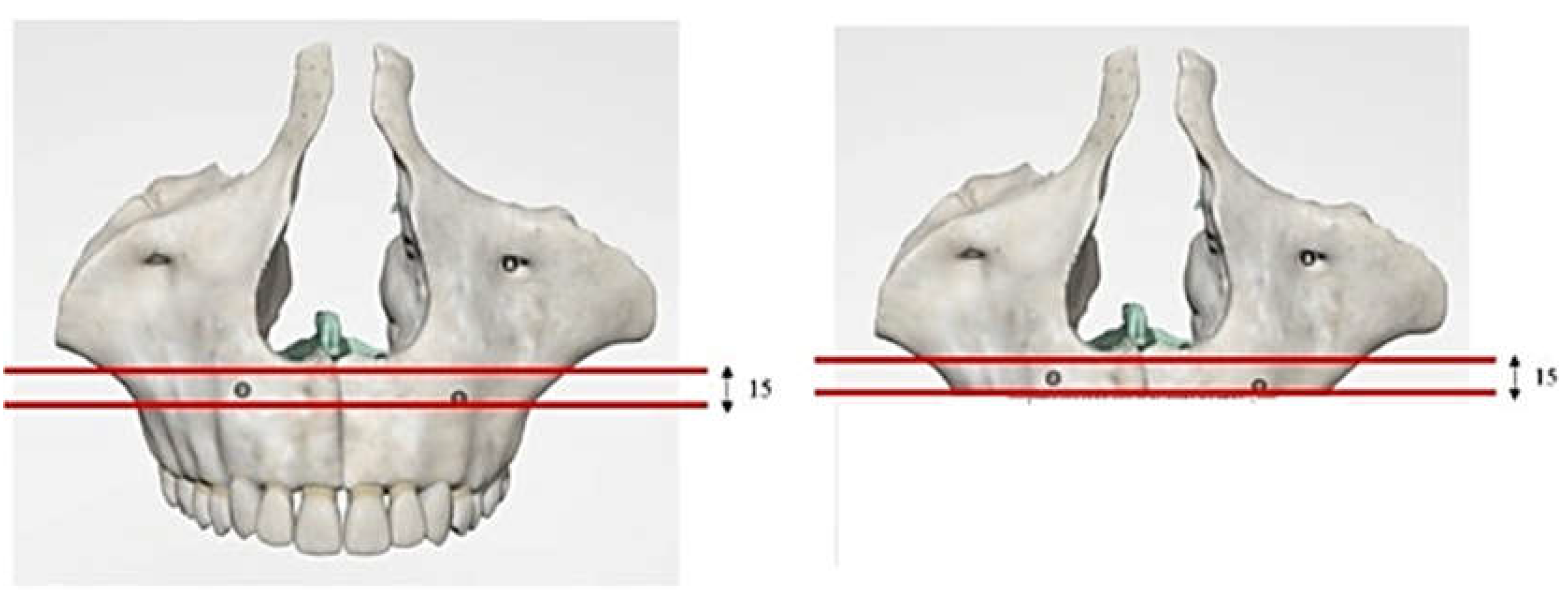
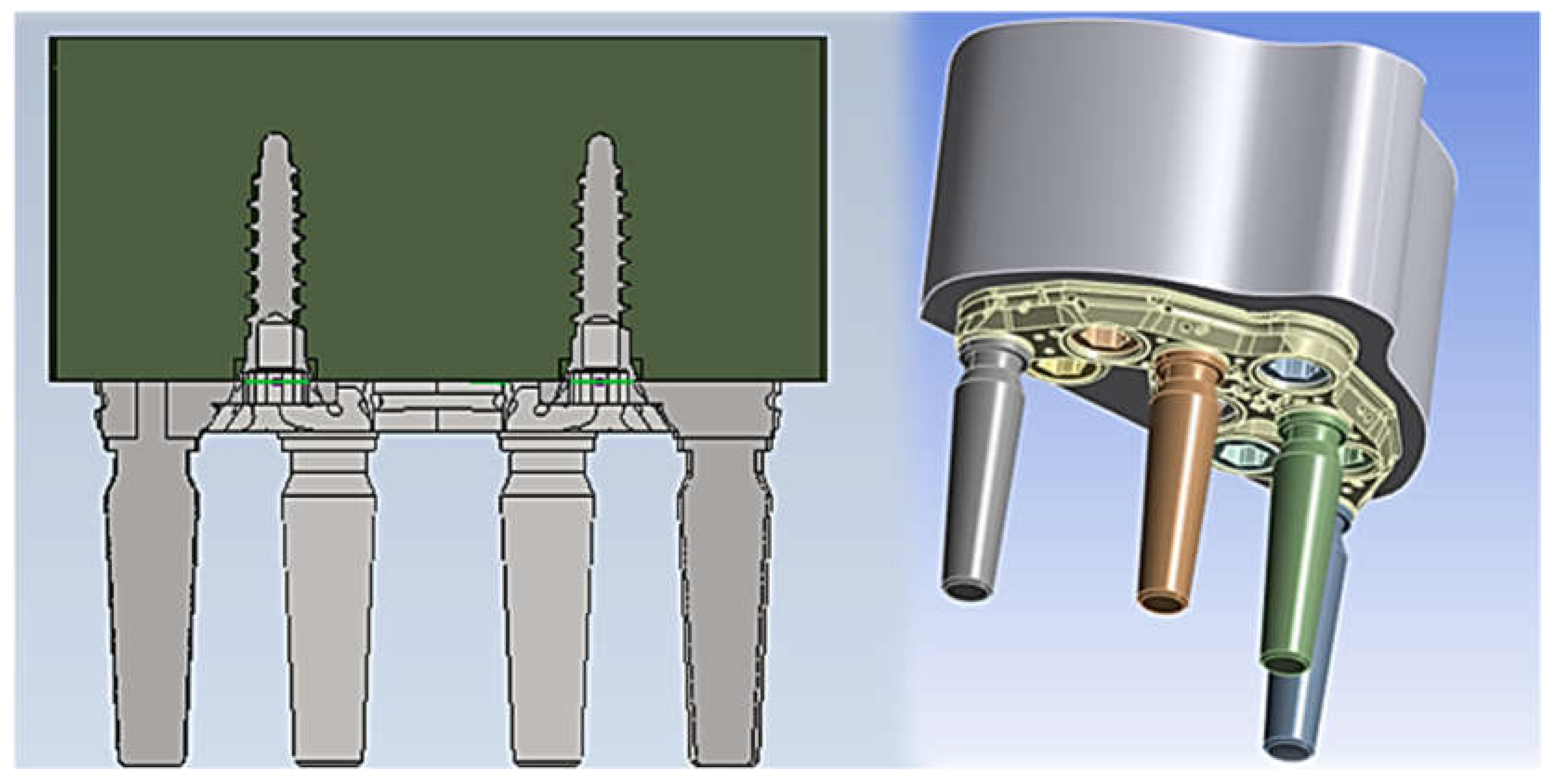
A 3D model was created using the Autodesk Inventor CAD software of the implant system formed by the Premaxillary Device (PD), fixing implants and its corresponding abutments (Aldo Corbo Research and Innovation Srl, Canicattì (Agrigento), Italy (Figure 1). A virtual 3D model of a completely edentulous jaw was selected from the computed tomography (CT) database of the Renato Archer Information Technology Center (CTI, Campinas, São Paulo, Brazil). Using various 3D editing tools, the jaw was cut to simulate severe bone atrophy (Figure 2). Based on similar studies, [4] an atrophy of 8 to 15 mm was targeted. The removed portion was later used to create the simplified model, and then the PD was placed on the bone model (Figure 3).
The conventional insertion of an implant must be supported by an adequate amount of bone. Considering that for the upper maxilla it is possible to exploit all the bone height available between the bone crest and the floor of the maxillary sinus, implants of 12 mm in length were considered considering the thickness of the PD of about 2.5 mm.

2.2. Materials

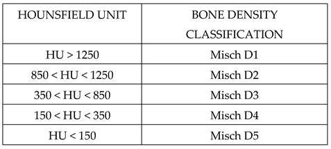
The bone on which the PD is positioned is the basal bone which has different mechanical characteristics from both cortical and trabecular bone. The elastic properties (elastic modulus and hardness) of the bone in contact with the implant play a fundamental role in determining the stability and success of the implant. In this regard, several publications have described the mechanical properties of cortical and spongy bone, but there are few studies in the literature regarding the characteristics of basal bone. However, through the knowledge of the density and through mathematical relationships it was possible to trace the value of the stiffness. Clinical bone density data can be accurately detected by computed tomography analyzed with specific programs for dentistry. The CT data assigns to each voxel a number that is dependent on the average density of tissues in that specific unit volume. This number, which can be highlighted on the X-ray Areas of Interest (ROI: Region Of Interest), is part of a standardized scale of densities expressed in Hounsfield Units (HU). It can take values between -1500 and +2595 and associates the density of water with a value of 0 while that of air with values close to -1500. Bone structures on the Hounsfield scale vary between +150 and +1500. It is possible to relate the data in Hounsfield units according to the Misch classification, as shown below in Table 1.
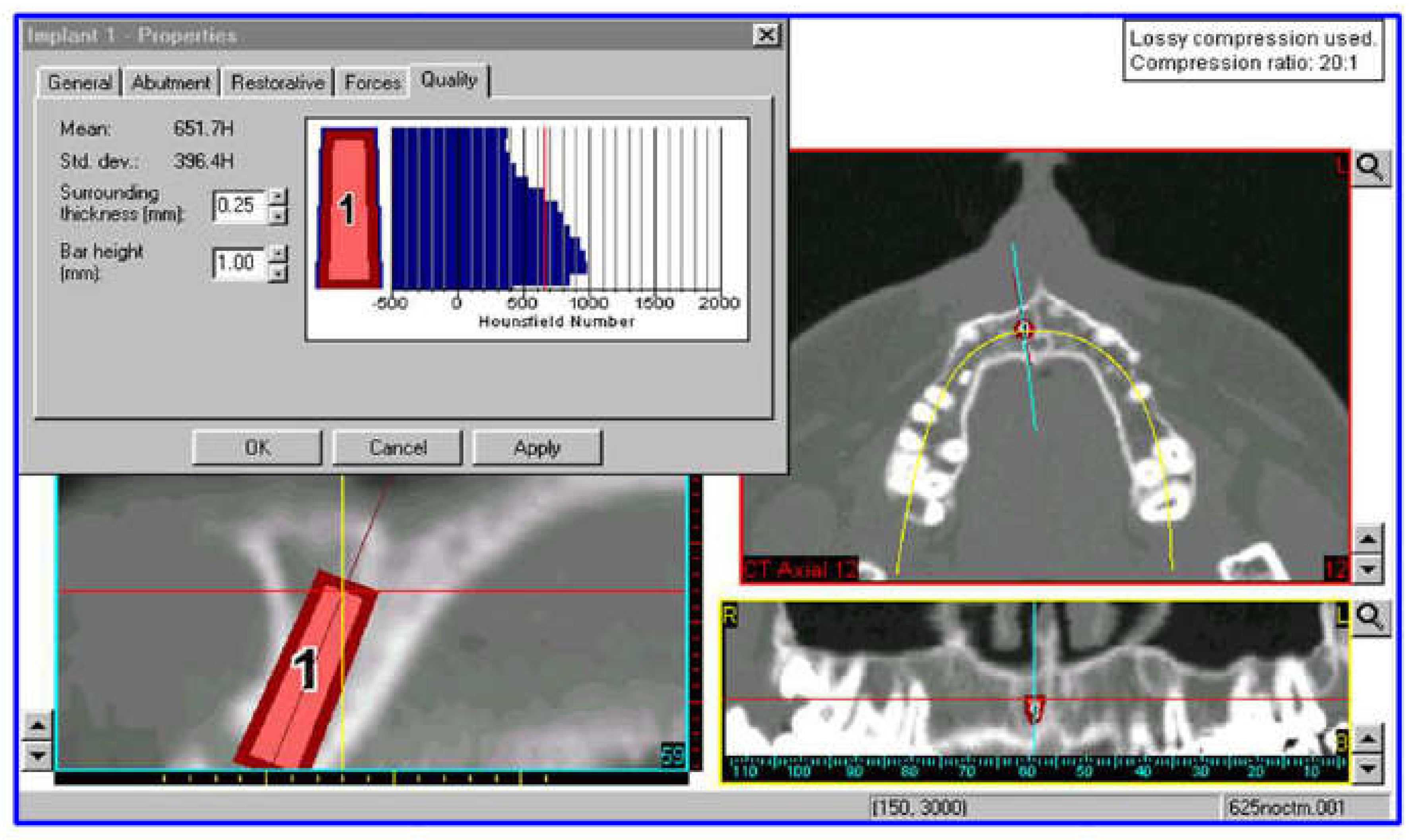
From a study carried out (Figure 4) it can be assumed, in first approximation, that the HU density of the jaw turns out to be around 650 HU, therefore the jaw can be classified according to Mish type D3. The estimated density is 0.62g/cm3.
Through a study performed by Seong et al. [5], who evaluated the elastic properties of the edentulous maxilla and mandible, it was possible to obtain the following mechanical properties, reported in Table 2.
For implants, abutments, and PD the Ti6Al4V titanium alloy was used as a material, the related mechanical properties are shown in Table 3 [6]. Titanium, used for the realization of all components, presents some problems among which it can induce the problem of stress shielding and therefore loss of the implant and bone. This phenomenon is caused by its high elastic modulus (110 Gpa) compared to bone (14 Gpa).
For both materials, isotropic behaviors have been assumed, in which the mechanical characteristics did not change with the direction.

2.3. FEM Modeling

Models previously built with CAD software (Inventor) were processed and exported to finite element software (ANSYS Inc., Canosburg, PA, USA). The hypothesis that was used for the simulation is that the materials had linear elastic behavior and homogeneous and isotropic characteristics. Their properties have been described by Young's module and Poisson's ratio in Table 2 and Table 3.
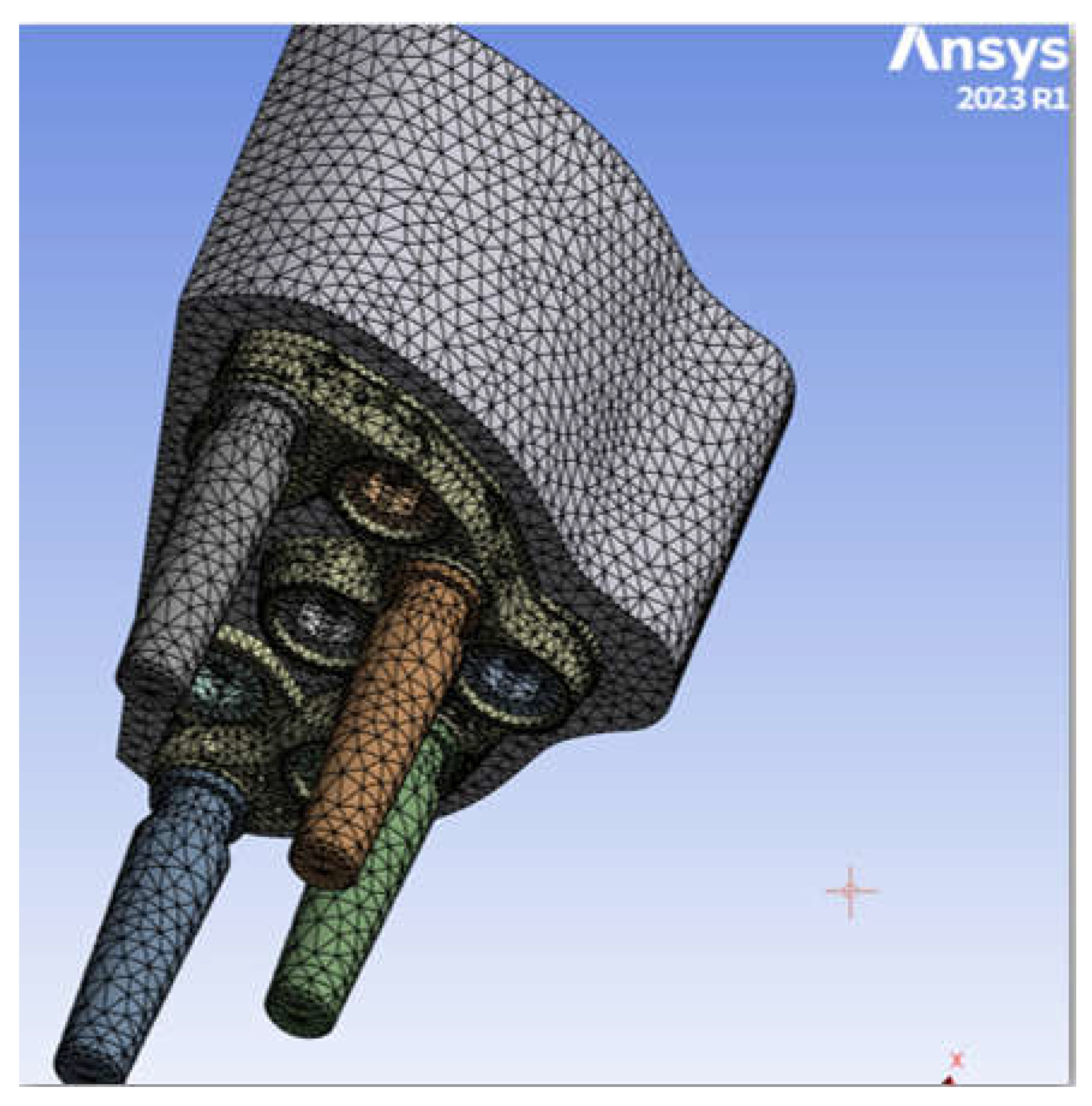
The PD was securely attached to the jaw. Abutment-implants have been inserted in the corresponding housings. To achieve high computational accuracy, the mesh used to discretize 3D into small elements to facilitate resolution was 0.5 mm There are four distinct types of mesh elements: linear tetrahedral, quadratic tetrahedral, linear hexahedric and quadratic hexahedral. A quadratic mesh element employs a nonlinear form function in which nodes are interpolated using a higher-order polynomial. According to Ansys, the preferred choice for complicated nonlinear geometry is tetrahedral mesh elements. Therefore, the default option for creating the element type is left [7] (Figure 5). The tetrahedral elements have been adapted for all structures with minimum and maximum dimensions (from 0.15 to 0.7 mm). All the regions where greater stress has been noted, have been manually finished with the aim of better controlling the actual distribution of stresses at fittings and edges. The 3D models had a large number of 2,658,021 elements.
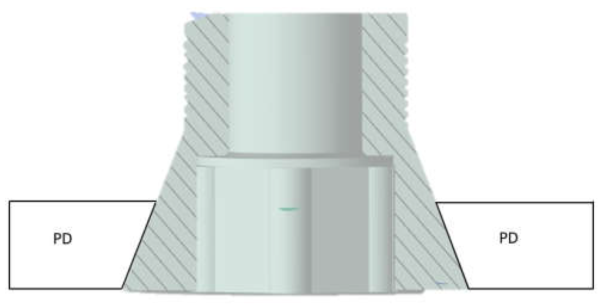
Before performing the FEA, it was necessary to simulate the PD screw and PD abutment contact, through the assignment of the corresponding contact surface and assigning the contact conditions that would simulate the system more accurately. In particular, as regards the type of connection between implant and PD, observing the figure [1] we note how the taper made on the hole of the PD is the same as the screw head, for this reason we can say that there is a conical connection to the screw-PD interface.
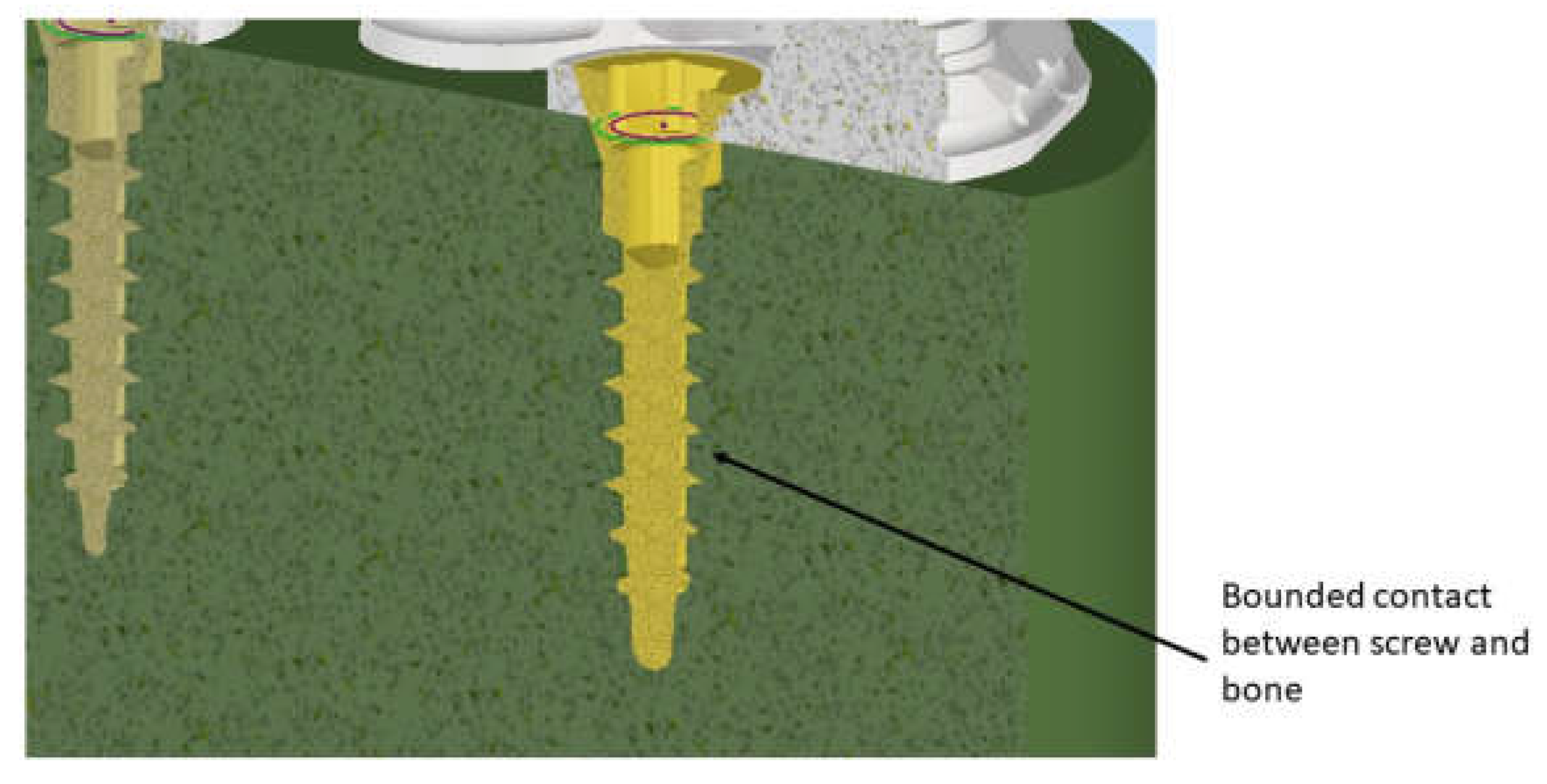
A further aspect, extremely fundamental, concerns the problem related to any relative micromovement existing at the bone implant interface. It is now evident that to ensure bone regeneration and to avoid implant failure, it is necessary to achieve an optimal level of osseointegration, the fundamental prerequisite is the immobility of the implant within the implant site. To model, therefore, the bone-implant contact was used the option of fixed connection between bone and screw. This option constrains the movements in the three directions x, y, z and the corresponding rotations; with this precaution the immobility of the screw inside the bone is guaranteed (Figure 7).
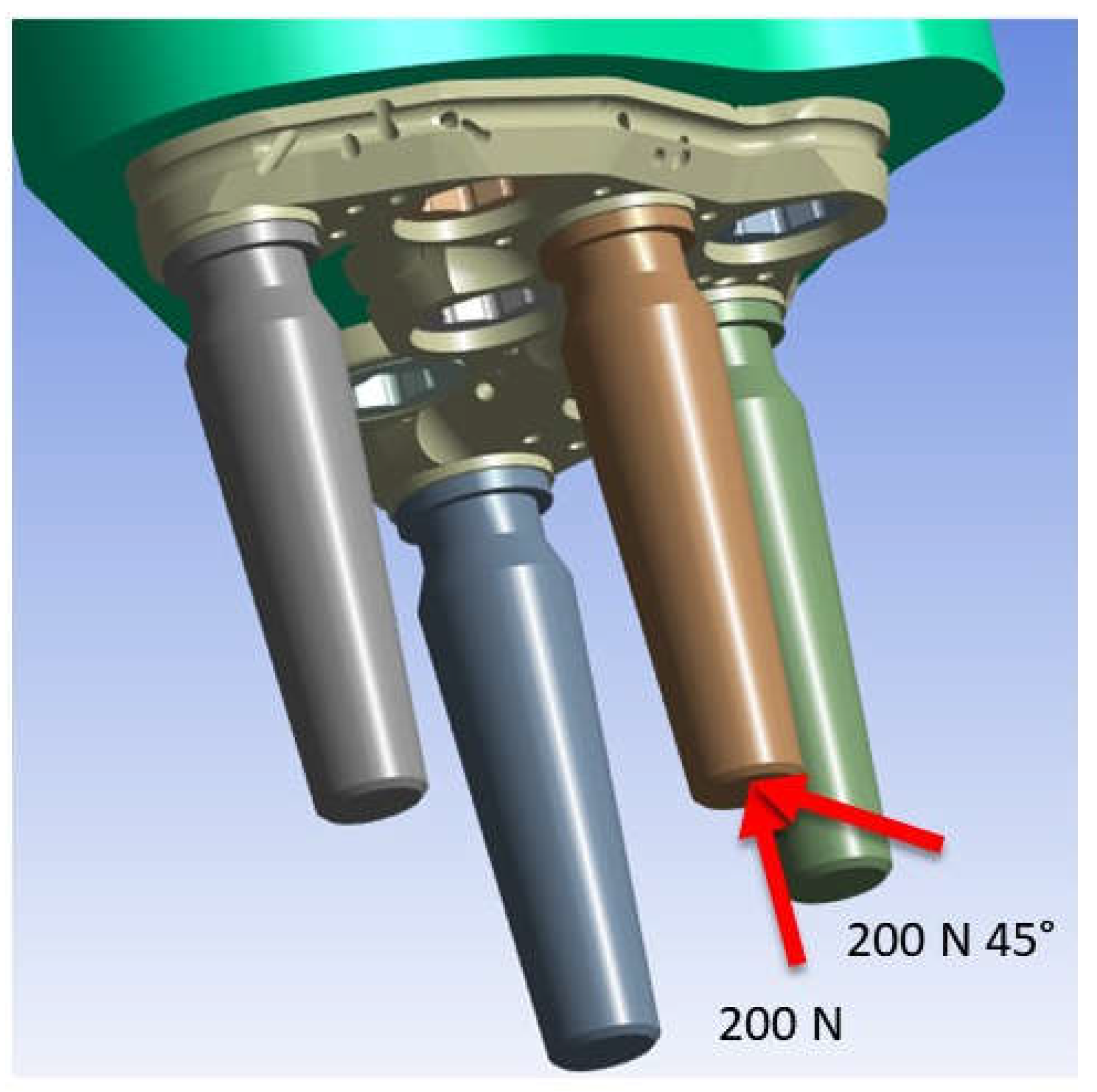
The occlusal surface of the abutment has been subjected to two loading conditions, the first, provides for the application of a load of 200 N along the apical direction, the second provides for the application of the same inclined load instead at 45 ° (Figure 8). In this way, the variation of the maximum Von Mises stress as the inclination changes is highlighted [8].

3. Results

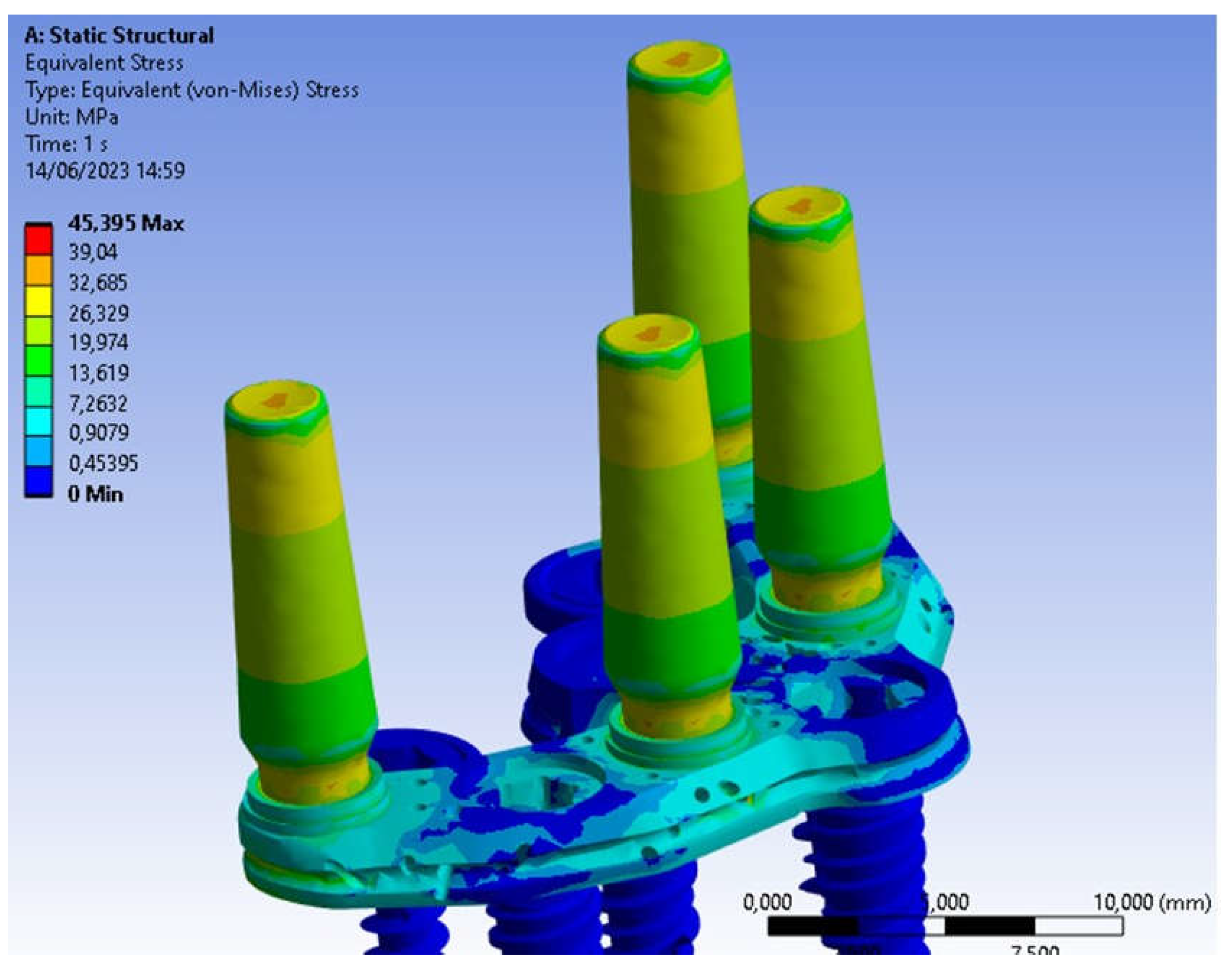
Regarding the application of the 200N load along the apical direction, Figure 9 shows the Von Mises stress distribution for the entire system.
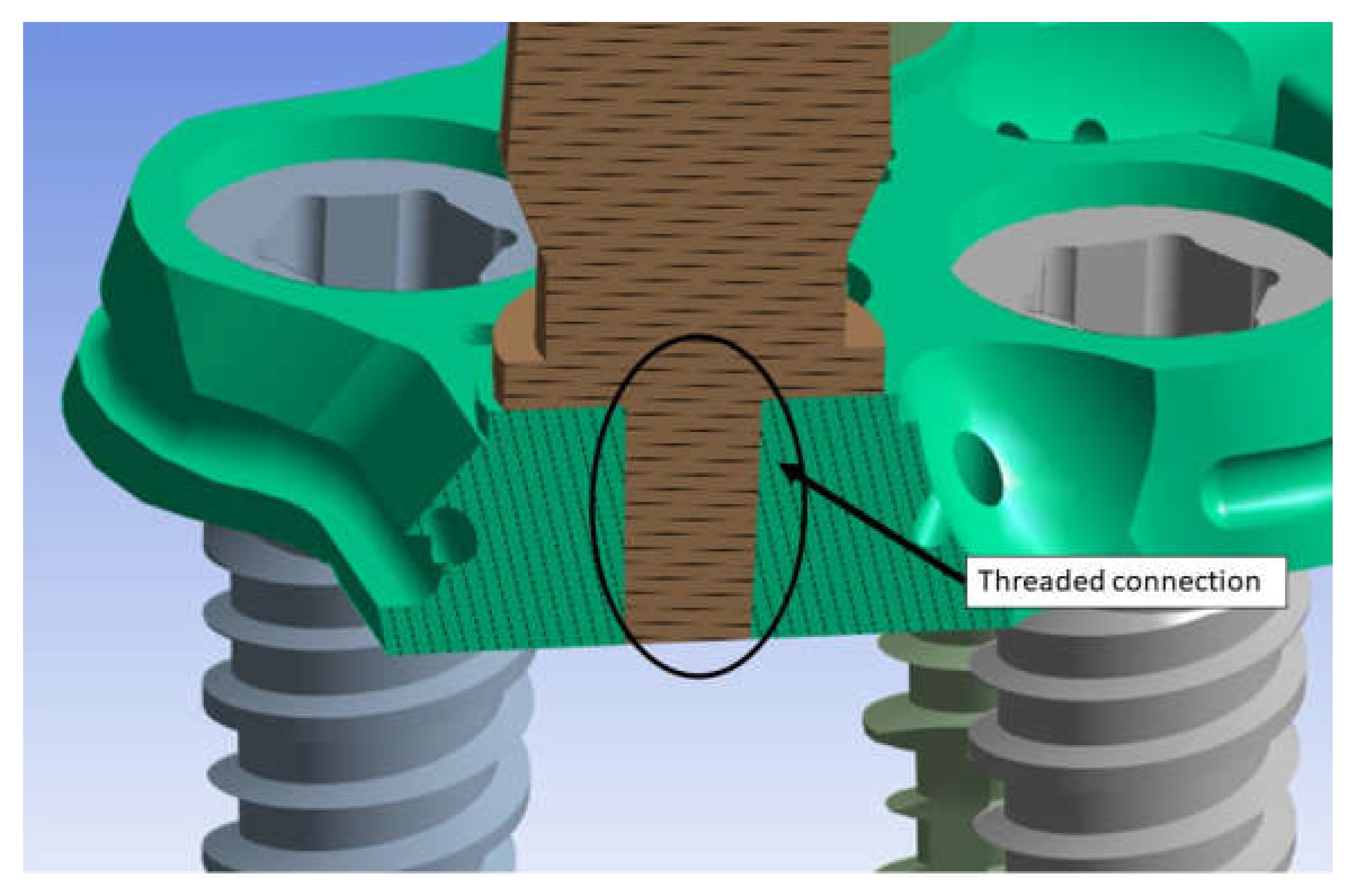
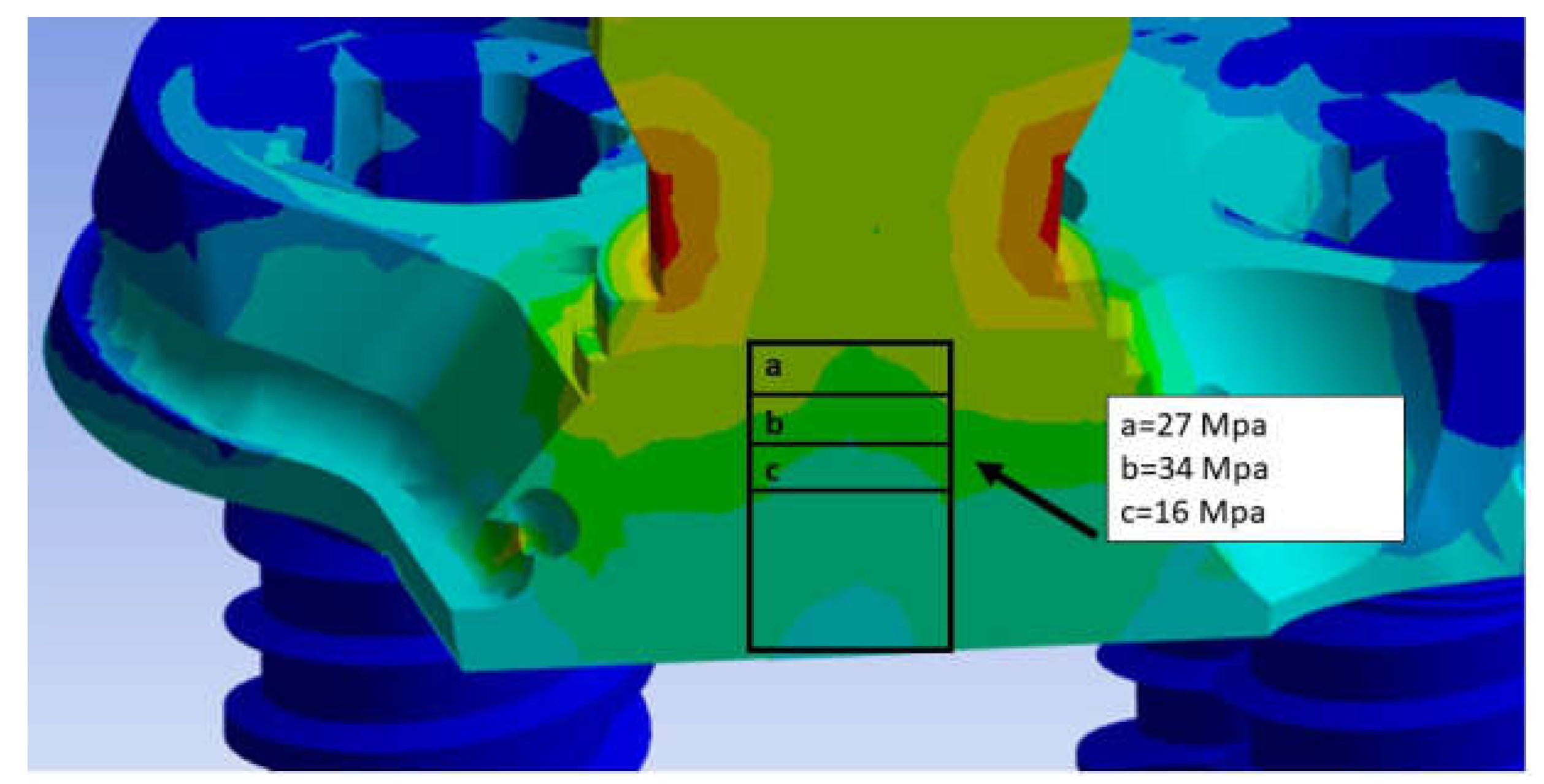
The Von-Mises distribution is uniformly distributed over the entire surface of the PD, presenting alterations in the proximity of the abutments in which the forces are exchanged with the outside. In particular, we observe that on the PD there are stress values between 5 Mpa and 15 Mpa. While as far as abutments are concerned, being the only components subject directly to the load, they are the most stressed. In particular, the conic geometry shows how the distribution decreases from the upper area of the abutment (yellow part), 27 Mpa up to about 13.62 Mpa (green part). The narrow section at the threaded connection, turns out to be the area where tickling, reach values of about 34.40 Mpa. Therefore, it is the most critical area of the whole system as higher stress values are recorded. The abutments are connected with the PD through a threaded connection as shown in Figure 10. This connection involves the application of a tightening torque equal to 10N*cm. This torque stresses the threads of the torsion and traction abutment. Since this area is the most critical, Figure 11 shows the Von Mises distribution between the abutment threads and the PD. It can be observed that the first 3 threads are the most stressed, in fact there are stress values between 20 Mpa and 45 Mpa. In a future structural optimization, it can therefore be thought to further decrease the thickness of the PD considering the fact that not all the length of the abutment thread exchanges efforts with the PD.
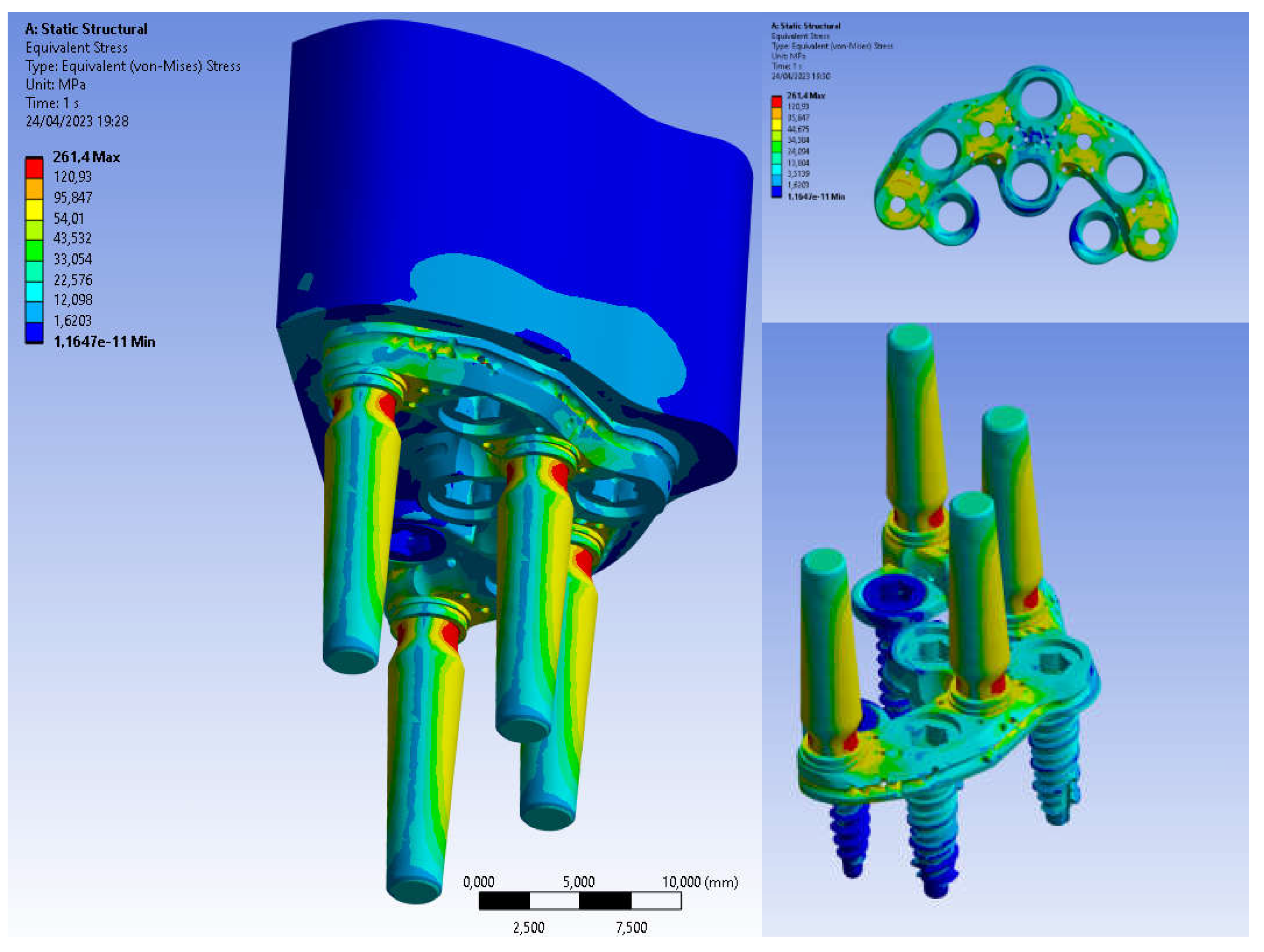
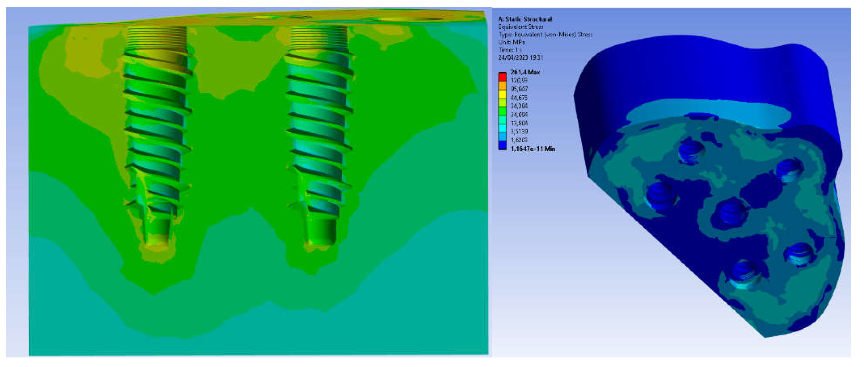
The application instead of the load of 200 N inclined at 45 ° shows an increase in stress on all components including the bone that has been simulated in this configuration as it is the most critical. The maximum Von Mises stress values are shown in Figure 12. Maximum stress on the basal bone was concentrated mainly in the bone interface region and PD (3-15 Mpa). Regarding the PD, because of its geometry it can evenly distribute the Von-Mises stresses. In fact, looking at Figure 13, stress values between (40 Mpa and 250 Mpa) are reached. These values suggest that it is possible to further make a structural improvement on the PD in order to decrease its thickness and further limit the damage to soft tissues since, considering that the yield stress of the Ti6Al4V titanium alloy turns out to be about 800 Mpa we have a safety factor of about 3. With regard to implants, on the other hand, the maximum stress value is observed around the neck of the implant and between the first and third threads (22 Mpa). The abutments instead are the most stressed components (270 Mpa) due to the fact that the application of the inclined load at 45 ° induces the bending at the base of the abutment. Therefore, a design improvement in correspondence of this area could further improve the mechanical resistance considering also that the masticatory loads are variable over time and this means that the whole system is subject to the phenomenon of fatigue that leads to failure with loads that turn out to be lower than static ones [9,10-13].
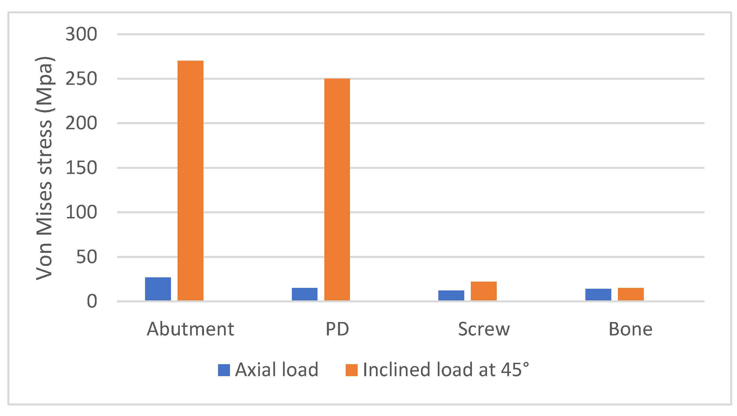
Comparing the results with the application of the load in the direction and inclinator at 45°, we can deduce the following graph (Figure 14) in which it is noted that the stress acting on the bone is little dependent on the angle of the load. Instead, observing in particular the abutment we notice how it went from a stress value of 34.40 Mpa to a value of about 270 Mpa. This shows how the tangential component of the load is critical for the System.

4. Discussion

Maxillary sinus augmentation is a viable technique that can be used to insert implants in a maxilla with reduced height. However, several complications can occur with this technique which can be classified into intraoperative, acute postoperative and chronic postoperative complications. In particular, the most frequent complications may be perforation of the Schneiderian membrane, intraoperative hemorrhage, infraorbital nerve injury, orbital wall perforation, implant displacement within the sinus, edema, infection of the inserted graft, flap dehiscence and formation of a fistula [14-25].
Thus, a valid alternative could be to use the ZI procedure, it has been reported to have a very high survival, but even with this procedure there are numerous studies which mention that the use of the Zi is not without complications.. The insertion of ZI represents a major surgical procedure that should be performed under general anesthesia by properly trained surgeons. The learning curve can be very long, and the brain and orbita may be interested in the procedure [26]. In recent years, static and dynamic navigation techniques have been used [27]. Sometimes, in the case of implants inserted in a more palatal position, a more complicated prosthetic restoration may be necessary [26]. Also, the eventual removal of failed implant could be a more complex procedure. Sinusitis has been reported in 3.9% of the cases, and a failure to obtain implant osseointegration in 2.44% [27]. In another review, the rate of complications was 7.2% when using an intrasinusal technique and 1.8% with an extrasinusal technique [16]. A 4.9% prosthetic complication rate was reported, with a 0.69 implant failure rate. In a clinical study on 141 implants inserted in 45 patients, an overall complication rate of 5,67% was reported [28]. In another clinical study on 182 ZI in 82 patients, a low complication rate was reported, sinusitis 10% and peri-implant hyperplasia 0.8%. Other reported complications have been oro-antral fistula, foreign body reaction, difficulties in maintaining proper oral hygiene in the posterior palatal region, transversal mobility, paresthesia, bruising, laceration of the lips, injury to the orbit and periorbital hematoma, cranial penetration, temporary deficts of some sensory nerves, soft tissue hypertrophy, abutment and prosthetic screw loosening, mucositis, prothesis fracture [28-30]. In a recent systematic review, the Authors conclude that ZI are not recommended as a first therapeutical option [25]. In pterygoid implants (PI) a success rate, after one year of 97.05% was reported [4]. In a systematic review, a cumulative survival over a 10 years period was riported for PI [23]. In another systematic review on 1983 PI in 634 patients a mean survival rate of 94.87 was reported [31]. Bidra et al reported [3] in another systematic review of PI, a 95.5% cumulative survival rate after 6 years. Recently, Wilkirson et al. reported on a FEA study on PI [32] . Subperiosteal implants were proposed and introduced in Sweden during the ‘40s, and have been extensively used in the ’50 and ’60 [33]. However, they had a too high percentage of complications and failures. In those years, the construction technique of this type of implant was extremely complex, a perfect adaptation of the implant to the underlying bone was very difficult to obtain, the surgical technique was very complicated and very time consuming. Moreover, these implants tended to be very large and they required very large flaps to position them on the underlying bone bed. Two surgeries were, furthermore, needed, with a high biological cost: one for the impression of the bone, the second for implant positioning. The used materials were chrome-cobalt and vitallium [34]. Stvrecky e coll.,[35] in a 15-year retrospective study, reported a 5–10-year survival rate of 58.3%. In the past few years, thanks to the introduction and widespread use of new digital technologies and metals, subperiosteal implants have been proposed again [36-38]. 3D metal printing has allowed a much better accuracy during the implant manufacturing [37,38]. The use of different metals, i.e., titanium, has allowed to obtain a smaller implant structure [36]. Nowadays, subperiosteal implants could offer advantages, e.g., reduction of treatment period, reduction of costs, avoidance of complex and risky surgical procedures [39]. In recent years, several studies point to the fact that with these subperioseal implant of the next generation no resorption of the underlying bone, mobility or fracture of the implant have been reported [39]. Moreover, 95% survival rates have been reported. However, only small numbers of patients with very short periods of follow-up can be found in the literature. Some reported complications have been swelling, edema, pain, implant exposure [37]. Overall, the response of the patients has been extremely positive regarding their comfort, chewing capabilities and the stability of the prosthetic restauration [38]. These results are probably related to the use of all the new digital technologies, which allow an extremely precise and close apposition of the implant structure to the underlying bone. Ten patients have been followed for one year; the Authors reported a 100% implant survival percentage, and 10% of early complications and 20% of late complications [39]. No complications or implant loss were reported in 16 patients, with a one year follow-up [40]. In a clinical study on 16 patients, with a 6 months follow-up, only one implant loss, without other relevant complications, was present.
The stresses caused by the prosthesis during chewing cannot be measured in vivo. The methods used can be experimental such as strain gauges using electrical strain gauges and photoelasticity. However, each method has its limitations, for example the disadvantage of strain gauges is that the measurement is limited by the area where the strain gauge is applied, which may not include the area of interest. The method instead of photoelasticity allows instead to identify gradients of stress over the entire structure. Its disadvantage consists in recreating a reflective model that in the case of complex structures is difficult [41-43]. FEA has proven to be a useful tool for estimating stress and strain in this innovative implant system. One of the peculiarities of FEA lies in its physical similarity between real results in vivo and numerical ones. However, further simplification of the geometry can inevitably lead to inconsistent results [41-44]. Consistent results in FEA must provide the complete geometry of the implant and surrounding bone to be modeled, material properties, loading constraints and conditions, and mesh convergence tests. The main advantages of the FEA methodology are essentially to be found in the non-invasive technique, static and dynamic tests can be performed, the study can be carried out several times and there is no need to sacrifice animals, therefore also from an ethical point of view it is extremely useful.
However, this methodology also has drawbacks which substantially concern the knowledge of the software, the fact that the results are dependent on the configuration parameters and the need for in-depth information on the behavior of the analyzed components.
One of the last aspects to consider are the results, they are provided through Von Mises solicitation and the best way to validate these FEA results is to simultaneously perform in vivo experimental studies [41]. In fact, FEA is a numerical investigation method that cannot realistically simulate the behavior of tissues, but can reproduce it approximately and provide predictive results. Also, since FEA is a numerical method, it suffers from possible numerical errors. Therefore, although there are advantages to using this method, randomized clinical trials on this topic must be performed to obtain accurate and definitive results.

5. Conclusions

In this work, the stress distribution in the PD device in its abutment and implant components was numerically investigated by means of three-dimensional linear elastic static finite element analysis. The three-dimensional geometry of the jaw was generated using computed tomography. The perfect jaw photos were prepared using CT-scan technology. The three-dimensional numerical models were created using Autodesk Inventor software.
Based on the results of the present study, it can be concluded that:
  • The PD treatment concept has shown a most favorable biomechanical behavior and can be considered a viable alternative for rehabilitation of severe atrophic maxilla;
  • The most rigid materials, such as titanium alloys, showed the most favorable biomechanical behavior and reduced stress levels for bone, implants, screws, and abutments;
  • Stress values did not exceed the bone strength limits for basal bone and titanium alloy;
  • The application of inclined load increases stress on all areas.
However, these results were obtained through a mathematical model, which cannot fully represent the complexity of the biological field.
All materials were considered homogeneous, isotropic and linearly elastic and It has been assumed that between the bone and the implant there is 100% osseointegration. Although such assumptions do not occur in clinical practice, they are common in FEA studies. Bone is a biologically complex structure without a defined pattern of behavior; Its characteristics differ between individuals and mechanical properties may vary over time [45]. The current assumptions adopted in this study are consistent with other FEA studies [46,47]. Also in this study, a unilateral static load was applied. Cyclic loads such as those that occur during chewing could lead to different behavior for titanium structures, given the fragile nature of the material. In the initial chewing phase, food is placed on one side of the prosthesis and no type of occlusal contact occurs on the contralateral side, so for a first analysis the unilateral load can be assumed as a real hypothesis [48]. More studies are needed that simulate all treatment alternatives for atrophic jaw that also include dynamic forces that occur during chewing and consider the anisotropic and regenerative properties of bone. A more accurate investigation of the PD inserted into the mandibular bone requires a simulation of oral cavity conditions such as humidity, temperature, and the presence of a medium that also simulates saliva conditions. However, due to the difficulties involved, researchers often use the finite element method to simulate implants and bones. However, there are limitations when simulating the entire oral environment. But in conclusion, we can say that the FEA method with good approximation is able to study the biomechanical behavior of the implant.

Author Contributions

Conceptualization, B.T. and A.C.; methodology, M.C., M.T. and T.R.; software, M.C.; validation, B.T., A.P. and F.I.; formal analysis, M.C. and A.S.; investigation, A.C.; resources, A.C. and B.T.; data curation, N.D.P.; writing—original draft preparation, A.P., M.C. and B.T.; writing—review and editing, N.D.P. and T.R.; visualization, A.P. and F.I.; supervision, A.C. and B.T.; project administration, A.P. and B.T. All authors have read and agreed to the published version of the manuscript.

Funding

This research received no external funding.

Institutional Review Board Statement

Not applicable.

Informed Consent Statement

Not applicable.

Data Availability Statement

All experimental data to support the findings of this study are available contacting the corresponding author upon request.

Conflicts of Interest

The authors declare no conflict of interest.

References

  1. Ramezanzade S, Yates J, Tuminelli FJ, Omid Keyhan S , Yousefi P, Lopez-Lopez J Zygomatic implants placed in atrophic maxilla: an overview of current systematic reviews and meta-analysis Maxillofac Plast Reconstr Surg 2021;43:1.
  2. Sales PH , Gomes MV , Oliveira-Neto OB , de Lima FJ, Leão JC Quality assessment of systematic reviews regarding the effectiveness of zygomatic implants: an overview of systematic reviews Med Oral Patol Oral Cir Bucal 2020;25:e541-e548.
  3. Bidra AS, Huynh-Ba G Implants in the pterygoid region: a systematic review of the literature Int J Oral Maxillofac Surg 2011;40:773-81.
  4. Peñarrocha-Oltra D, Candel-Martí E, Ata-Ali J, Peñarrocha-Diago M. Rehabilitation of the atrophic maxilla with tilted implants: review of the literature. J Oral Implantol. 2013 Oct;39(5):625-32. Epub 2011 Nov 28. PMID: 22121829. [CrossRef]
  5. Seong WJ, Kim UK, Swift JQ, Heo YC, Hodges JS, Ko CC. Elastic properties and apparent density of human edentulous maxilla and mandible. Int J Oral Maxillofac Surg. 2009 Oct;38(10):1088-93. Epub 2009 Jul 31. PMID: 19647417; PMCID: PMC2743800. [CrossRef]
  6. Feras Haroun and Oguz Ozan. Evaluation of Stresses on Implant, Bone, and Restorative Materials Caused by Different Opposing Arch Materials in Hybrid Prosthetic Restorations Using the All-on-4 Technique. Materials 2021, 14(15), 4308. [CrossRef]
  7. Bhering, C.L.B.; Mesquita, M.F.; Kemmoku, D.T.; Noritomi, P.Y.; Consani, R.L.X.; Barão, V.A.R. Comparison between all-on-four and all-on-six treatment concepts and framework material on stress distribution in atrophic maxilla: A prototyping guided 3D-FEA study. Mater. Sci. Eng. C 2016, 69, 715–725. [CrossRef]
  8. Oh, J.-H.; Kim, Y.-S.; Lim, J.Y.; Choi, B.-H. Stress Distribution on the Prosthetic Screws in the All-on-4 Concept: A Three- Dimensional Finite Element Analysis. J. Oral Implant. 2020, 46, 3–12. [CrossRef]
  9. Kitamura E, Stegaroiu R, Nomura S, Miyakawa O. Biomechanical aspects of marginal bone resorption around osseointegrated implants: considerations based on a three-dimensional finite element analysis. Clin Oral Implants Res. 2004 Aug;15(4):401-12. PMID: 15248874. [CrossRef]
  10. Duyck, J.; Vandamme, K. The effect of loading on peri-implant bone: A critical review of the literature. J. Oral Rehabil. 2014, 41, 783–794. [CrossRef]
  11. Erkmen, E.; Meriç, G.; Kurt, A.; Tunç, Y.; Eser, A. Biomechanical comparison of implant retained fixed partial dentures with fiber reinforced composite versus conventional metal frameworks: A 3D FEA study. J. Mech. Behav. Biomed. Mater. 2011, 4, 107–116. [CrossRef]
  12. Bijjargi, S.; Chowdhary, R. Stress dissipation in the bone through various crown materials of dental implant restoration: A 2-D finite element analysis. J. Investig. Clin. Dent. 2012, 4, 172–177. [CrossRef]
  13. Elsayyad, A.A.; Abbas, N.A.; AbdelNabi, N.M.; Osman, R.B. Biomechanics of 3-implant-supported and 4-implant-supported mandibular screw-retained prostheses: A 3D finite element analysis study. J. Prosthet. Dent. 2020, 124, 68.e1–68.e10. [CrossRef]
  14. Mahmoud Al-Dajani, DDS, MSc, PhD (OMFS), MSc, FRCD(C) (DPH). Recent Trends in Sinus Lift Surgery and Their Clinical Implications. [CrossRef]
  15. Stephen S Wallace, Dennis P Tarnow, Stuart J Froum, Sang-Choon Cho, Homayoun H Zadeh, Janet Stoupel, Massimo Del Fabbro, Tiziano Testori. Maxillary sinus elevation by lateral window approach: evolution of technology and technique. journal of Evidence Based Dental Practice. [CrossRef]
  16. Gutiérrez Muñoz D , Obrador Aldover C, Zubizarreta-Macho A, González Menéndez H, Lorrio Castro J, Peñarrocha Oltra D, Montiel-Company JM, Hernández Montero S Survival Rate and Prosthetic and Sinus Complications of Zygomatic Dental Implants for the Rehabilitation of the Atrophic Edentulous Maxilla: A Systematic Review and Meta-Analysis Biology (Basel) 2021;10:601.
  17. Hsu YT, Rosen PS, Choksi K, Shih MC, Ninneman S, Lee CT Complications of sinus floor elevation procedure and management strategies: A systematic review Clin Implant Dent Relat Res 2022;24:740-765.
  18. Agliardi EL, Panigatti S , Romeo D, Sacchi L, Gherlone E Clinical outcomes and biological and mechanical complications of immediate fixed prostheses supported by zygomatic implants: A retrospective analysis from a prospective clinical study with up to 11 years of follow-up Clin Implant Dent Relat Res 2021;23:612-624.
  19. Marin S, Kirnbauer B, Rugani P, Payer M, Jakse N Potential risk factors for maxillary sinus membrane perforation and treatment outcome analysis ClinImplant Dent Relat Res 2019;21:66-72.
  20. Solà Pérez A, Pastorino D, Aparicio C, Pegueroles Neyra M, Sannam Khan R, Wright S, Ucer C Success Rates of Zygomatic Implants for the Rehabilitation of Severely Atrophic Maxilla: A Systematic Review Dent J (Basel) 2022;10:151.
  21. Al-Dajani M Incidence, Risk Factors, and Complications of Schneiderian Membrane Perforation in Sinus Lift Surgery: A Meta-Analysis Implant Dent 2016;25:409-15.
  22. Yalçın M, Can S, Akbaş M, Dergin G, Garip H, Altuğ Aydil B, Varol A Retrospective Analysis of Zygomatic Implants for Maxillary Prosthetic Rehabilitation Int J Oral Maxillofac Implants 2020;35:750-756.
  23. Peñarrocha M, Carrillo C, Boronat A, Peñarrocha M Retrospective study of 68 implants placed in the pterygomaxillary region using drills and osteotomes Int J Oral Maxillofac Implants 2009;24:720-6.
  24. Lan K, Wang F, Huang W, Davó R, Wu Y Quad Zygomatic Implants: A Systematic Review and Meta-analysis on Survival and Complications Int J Oral Maxillofac Implants 2021;36:21-29.
  25. Barone A, Santini S, Sbordone L, Crespi R, Covani U A clinical study of the outcomes and complications associated with maxillary sinus augmentation Int J Oral Maxillofac Implants 2006;21:81-5.
  26. Molinero-Mourelle P, Baca-Gonzalez L, Gao B, Saez-Alcaide LM, Helm A, Lopez-Quiles J. Surgical complications in zygomatic implants: A systematic review. Med Oral Patol Oral Cir Bucal. 2016 Nov 1;21(6):e751-e757. PMID: 27694789; PMCID: PMC5116118. [CrossRef]
  27. Goiato MC, Pellizzer EP, Moreno A, Gennari-Filho H, dos Santos DM, Santiago JF Jr, dos Santos EG. Implants in the zygomatic bone for maxillary prosthetic rehabilitation: a systematic review. Int J Oral Maxillofac Surg. 2014 Jun;43(6):748-57. Epub 2014 Feb 14. PMID: 24530034.. [CrossRef]
  28. Jokstad A, Sanz M, Ogawa T, Bassi F, Levin L, Wennerberg A, Romanos GE. A Systematic Review of the Role of Implant Design in the Rehabilitation of the Edentulous Maxilla. Int J Oral Maxillofac Implants. 2016;31 Suppl:s43-99. PMID: 27228254. [CrossRef]
  29. Ramos Chrcanovic B, Nogueira Guimarães Abreu MH Survival and complications of zygomatic implants: a systematic review Oral Maxillofac Surg 2013;17:81-93.
  30. Araujo MP, Innes NP, Bonifácio CC, Hesse D, Olegário IC, Mendes FM, Raggio DP. Atraumatic restorative treatment compared to the Hall Technique for occluso-proximal carious lesions in primary molars; 36-month follow-up of a randomised control trial in a school setting. BMC Oral Health. 2020 Nov 11;20(1):318. PMID: 33176756; PMCID: PMC7656501. [CrossRef]
  31. Bai L, Zheng L, Ji P, Wan H, Zhou N, Liu R, Wang C Additively Manufactured Lattice-like Subperiosteal Implants for Rehabilitation of the Severely Atrophic Ridge. ACS Biomater Sci Eng. 2022;8:912-920.
  32. Wilkirson E, Chandran R, Duan Y Rehabilitation of Atrophic Posterior Maxilla with Pterygoid Implants: A 3D Finite Element Analysis. Int J Oral Maxillofac Implants. 2021;36:e51-e62.
  33. Leung M, Alghamdi R, Fernandez Guallart I, Bergamini M, Yc Yu P, J Froum SJ, Cho SC Patient-Related Risk Factors for Maxillary Sinus Augmentation Procedures: A Systematic Literature Review Int J Periodontics Restorative Dent 2021;41:e121-e128.
  34. Candotto V, Gallusi G, Piva A, Baldoni M, Di Girolamo M Complications in sinus lift J Biol Regul Homeost Agents 2020;34(1 Suppl. 1):139-142.
  35. Stvrtecky RC, Zarate JO, Borgetti ZA. Epithelial adhesion and subperiosteal implants. J Oral Implantol. 1989;15(1):62-5. PMID: 2634781.
  36. Nemtoi A, Covrig V, Nemtoi A, Stoica G, Vatavu R, Haba D, Zetu I Custom-Made Direct Metal Laser Sintering Titanium Subperiosteal Implants in Oral and Maxillofacial Surgery for Severe Bone-Deficient Patients-A Pilot Study. Diagnostics 2022;12:2531.
  37. Dimitroulis, Gupta B, Wilson I, Hart C The atrophic edentulous alveolus. A preliminary study on a new generation of subperiosteal implants Oral Maxillofac Surg 2022 Feb 4. [CrossRef]
  38. Mangano C, Bianchi A, Mangano FG , Dana J , Colombo M , Solop I, Admakin O. Custom-made 3D printed subperiosteal titanium implants for the prosthetic restoration of the atrophic posterior mandible of elderly patients: a case series 3D Print Med 2020;6:1.
  39. Van den Borre C, Rinaldi M, De Neef B, Loomans NAJ, Nout E, Van Doorne L, Naert I, Politis C, Schouten H, Klomp G, Beckers L, Freilich MM, Mommaerts MY. Patient- and clinician-reported outcomes for the additively manufactured sub-periosteal jaw implant (AMSJI) in the maxilla: a prospective multicentre one-year follow-up study. Int J Oral Maxillofac Surg. 2022;51:243-250.
  40. James RA, Lozada JL, Truitt PH, Foust BE, Jovanovic SA Subperiosteal implants. CDA J. 1988;16:10-4.
  41. Shilpa T. Finite element analysis: A boon to dentistry. J Oral Biol Craniofac Res. 2014;4:200–3. [PMC free article].
  42. El-Anwar MI, El-Zawahry MM. A three dimensional finite element study on dental implant design. J Genet Eng Biotechnol. 2011;9:77–82.
  43. DeTolla DH, Andreana S, Patra A, Buhite R, Comella B. Role of the finite element model in dental implants. J Oral Implantol. 2000;26:77–81.
  44. Van Staden RC, Guan H, Loo YC. Application of the finite element method in dental implant research. Comput Methods Biomech Biomed Engin. 2006;9:257–70.
  45. Rahmitasari F, Ishida Y, Kurahashi K, Matsuda T, Watanabe M, Ichikawa T. PEEK with reinforced materials and modifications for dental implant applications. Dent J (Basel). 2017;5(4):35. [CrossRef]
  46. Schwitalla A, Abou-Emara M, Spintig T, Lackmann J, Muller W. Finite element analysis of the biomechanical effects of PEEK dental implants on the peri-implant bone. J Biomech. 2015;48(1):1–7. [CrossRef]
  47. Chen X, Mao B, Zhu Z, et al. A three-dimensional finite element analysis of mechanical function for 4 removable partial denture designs with 3 framework materials: CoCr, Ti-6Al-4V alloy and PEEK. Sci Rep. 2019;9:13975. [CrossRef]
  48. Tribst JPM, de Morais DC, Alonso AA, Piva AMOD, Borges ALS. Comparative three-dimensional finite element analysis of implant-supported fixed complete arch mandibular prostheses in two materials. J Indian Prosthodont Soc. 2017;17(3):255–60. [CrossRef]
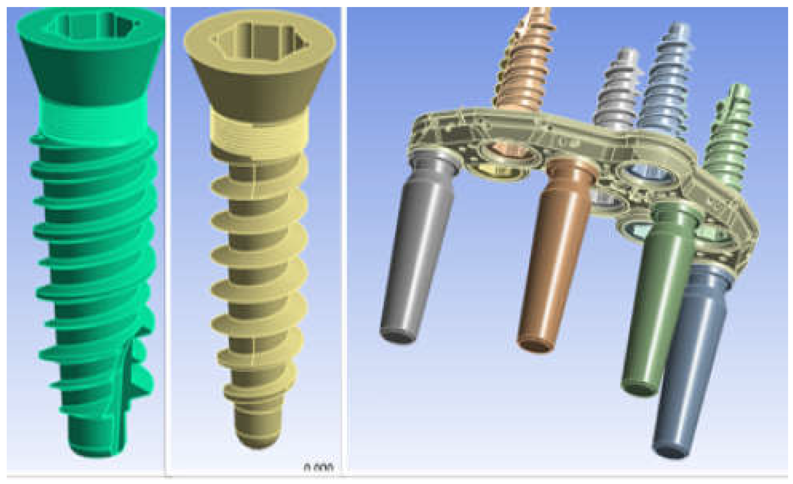
Figure 1. Premaxillary Device (PD) components.
Preprints 76752 g001
Figure 2. 3D model of the jaw with severe atrophy of the maxilla.
Preprints 76752 g002
Figure 3. 3D model of PD placed on bone model.
Preprints 76752 g003
Figure 4. Measurement of bone density in Hounsfield units at a fixture virtual insertion site using CT image processing with Simplant software (Materialise, Belgium).
Preprints 76752 g004
Figure 5. PD mesh model.
Preprints 76752 g005
Figure 6. Cone-Morse screw-PD type connection.
Preprints 76752 g006
Figure 7. Contact between screw and bone.
Preprints 76752 g007
Figure 8. Application of the 200 N load.
Preprints 76752 g008
Figure 9. Von-Mises stress for a load of 200 N in the apical direction.
Preprints 76752 g009
Figure 10. Threaded connection between abutment and PD.
Preprints 76752 g010
Figure 11. Von-Mises stress distribution in the threaded connection.
Preprints 76752 g011
Figure 12. Von Mises stress on Pd.
Preprints 76752 g012
Figure 13. Von Mises stress on Basal bone.
Preprints 76752 g013
Figure 14. Von Mises stress on all components in the case of axially applied load and inclined load at 45°.
Preprints 76752 g014
Table 1. Correspondence between Hounsfield Unit and bone density classification.
Preprints 76752 i001
Table 2. Mechanical properties of basal bone.
Preprints 76752 i002
Table 3. Mechanical properties of titanium alloy used for PD.
Preprints 76752 i003
Disclaimer/Publisher’s Note: The statements, opinions and data contained in all publications are solely those of the individual author(s) and contributor(s) and not of MDPI and/or the editor(s). MDPI and/or the editor(s) disclaim responsibility for any injury to people or property resulting from any ideas, methods, instructions or products referred to in the content.
Copyright: This open access article is published under a Creative Commons CC BY 4.0 license, which permit the free download, distribution, and reuse, provided that the author and preprint are cited in any reuse.
Prerpints.org logo

Preprints.org is a free preprint server supported by MDPI in Basel, Switzerland.

Subscribe

© 2024 MDPI (Basel, Switzerland) unless otherwise stated