Preprint
Article

A Computational Study on Structural and Thermal Behaviour of Disc Brake Rotors With Varying Design and Material

Altmetrics

Downloads

156

Views

58

Comments

0

Submitted:

15 June 2023

Posted:

19 June 2023

You are already at the latest version

Alerts
Abstract
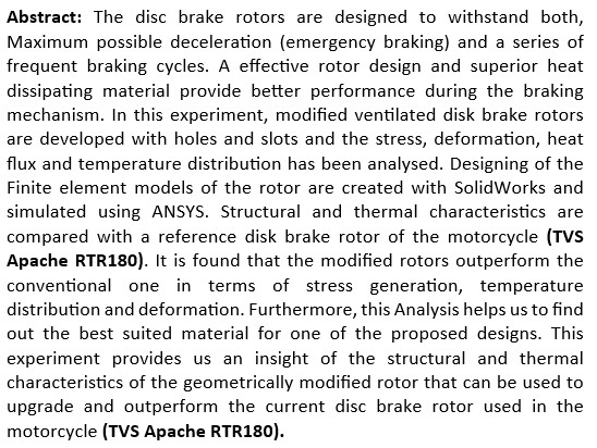
The disc brake rotors are designed to withstand both, Maximum possible deceleration (emergency braking) and a series of frequent braking cycles. A effective rotor design and superior heat dissipating material provide better performance during the braking mechanism. In this experiment, modified ventilated disk brake rotors are developed with holes and slots and the stress, deformation, heat flux and temperature distribution has been analysed. Designing of the Finite element models of the rotor are created with SolidWorks and simulated using ANSYS. Structural and thermal characteristics are compared with a reference disk brake rotor of the motorcycle (TVS Apache RTR180). It is found that the modified rotors outperform the conventional one in terms of stress generation, temperature distribution and deformation. Furthermore, this Analysis helps us to find out the best suited material for one of the proposed designs. This experiment provides us an insight of the structural and thermal characteristics of the geometrically modified rotor that can be used to upgrade and outperform the current disc brake rotor used in the motorcycle (TVS Apache RTR180).
Keywords: 
Subject: Chemistry and Materials Science  -   Metals, Alloys and Metallurgy

Introduction

The major feature of braking disc rotors is that they allow for rapid heat dispersion into the environment. Braking power is reduced when the braking system becomes overheated ([2] Ahmad, F., Sethi, M., Tripathi, R., et al. (2021)). While braking, the thermo-mechanical loads on the discs are extremely severe. Furthermore, when braking is applied, friction between brake pads and rotor increases which in-turn increases the temperature. To sustain such an amount of temperature of 200–300 degree Celsius, the brake rotor material needs to support major mechanical thermal stress ([4] Jafari, R. and Akyuz, R. (2022) [6] McPhee, A. D. and Johnson, D. A. (2008)). Moreover, to mitigate the judder, surface cracking and excessive wear of the rubbing faces which leads to brake fade and thermal induced stress cracks, in adverse conditions, it is obligatory to pass on the heat produced into the environment ([10] Sathishkumar, S., Jeevarathinam, A., Sathishkumar, K.,Kumar, K. G., et al. (2022)). Also, for an efficient brake material, features such like high heat conductivity, strong mechanical abrasion resistance, and an elevated surface to volume ratio are required. The effectiveness of a disc brake assembly undergoing thermal loads may be assessed by assessing the temp. recorded on mathematical models via simulations. In frequent years, much effort has been made in increasing the performance and also efficiency of brake discs. This enormous amount of work has aided the development of nonferrous copper alloys, aluminium, and composites based on carbon ([7] Ozkan, D., Gok, M. S., and Karaoglanli, A. C. (2020)). Studies have employed several computational methods, along with the Finite element method (FEM), to calculate the mating surface temp [8] Parab, V., Naik, K., and Dhale, A. (2014) [9] Parab, V., Naik, K., and Dhale, A. (2014)). Such factors im- pact the braking system’s performance and lifetime.

Model of disk brake rotor

The disc brakes' 3D model was created using the SolidWorks programme. The rotor disk's material of choice is stainless steel. It is assumed to be stress-free prior to using the brake. The effects of inertia and body force were deemed to be insignificant. In Figure 1, a real-world model (a) of motorcycle (TVS Apache RTR180) and two modified forms are shown. It should be noted that Figure 1 depicts the frontal view design and characteristics of the disc brake versions. Ansys was used to create and analyse each model in this study. Table 1 lists the characteristics that all models share in common.

Finite element modelling

The ANSYS platform was utilised in this investigation to create mesh and to examine the designed model's properties [11]. The mesh was generated using an 8-noded, 3-DOF tetrahedral element. The 8-node elements are appropriate for model boundaries and have matching temperature forms. Depending on the layout, the meshing has different node and element numbers. The target quality of the modelling is set to 0.05, additionally the smooth transition inflation option has been selected with the transition ratio of 0.272. The calculation and data collection for the structural and thermal analyses were done using these parameters.

Results and Analysis

(a).
Static structural analysis
Parameters such as displacement, tension, strain and strength are defined by static structural analysis, for each case, the disk brake was subjected to 960 N of braking force and a rotational velocity of 100km/h (27.77 rad/sec) during the braking operation.
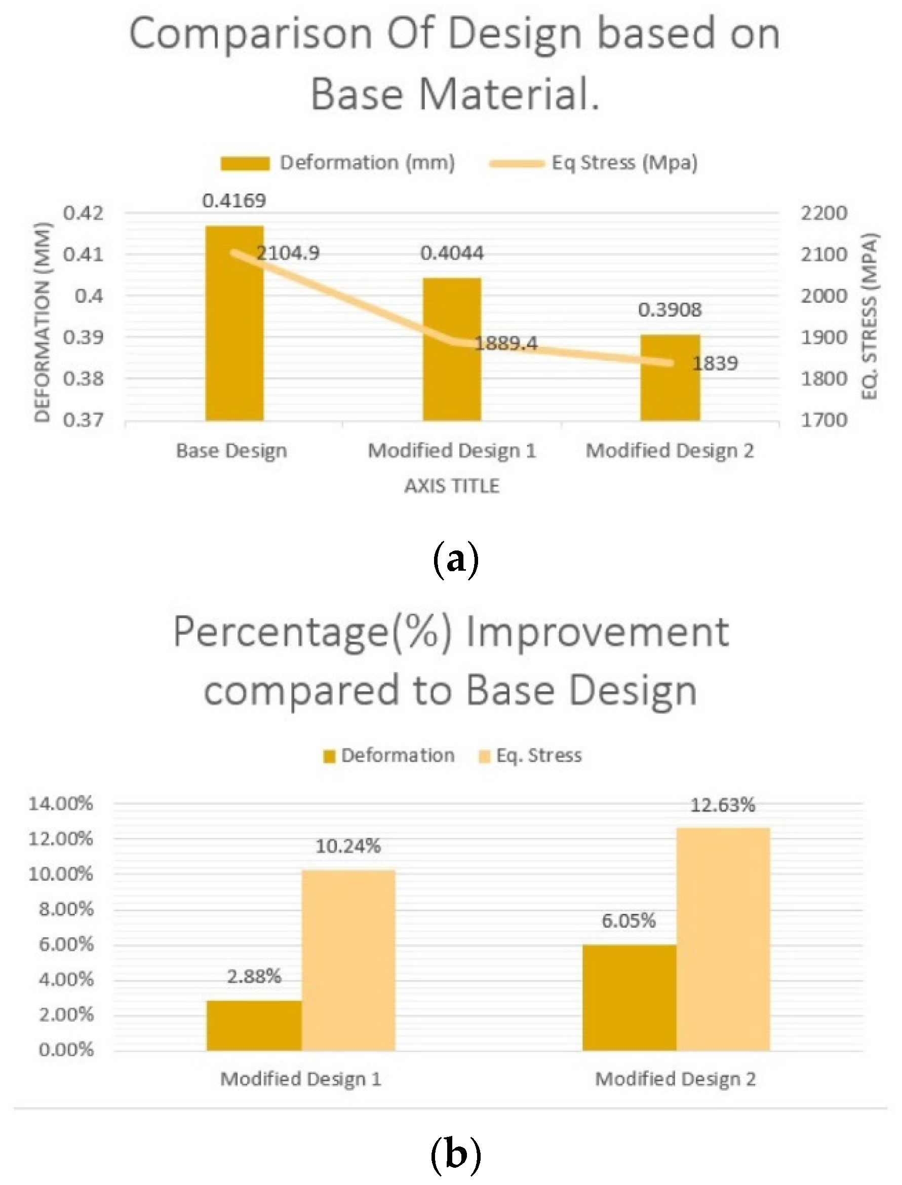
Figure 2 and Figure 3 visualize the deformation and equivalent (von-mises) stress acting upon the various models and the values are plotted in Figure 4. Figure 4a indicates that the maximum deformation that has been observed in Base Design whereas Modified Design 2 has undergone minimum deformation. Compared to the base model, Maximum equivalent (von-mises) stress has been found in Modified Design 1 and its minimum value in Modified Design 2. Showing a percentage improvement of 10.24% & 12.63% respectively. In Modified Design 1, maximum 2.88% improvement was seen in terms of deformation and Modified Design 2 offers a maximum improvement of 6.04% in terms of deformation. Thus, it is clear that the maximum percentage% improvement both in terms of eq. stress as well as deformation is seen in Modified Design 2.
  • (b). Thermal analysis
To explore and analyse various thermal variables, steady-state thermal analysis is used. Temperature distribution analysis enables the study of thermal stresses that may result in malfunctions like brake fade. In these circumstances, measures of thermal stress are made using temperature from the continuous thermal assessment. The peak temperature and heat flow are attained at the brake pad and disc contact surface. Figure 5 and Figure 6 respectively show the temperature distribution along the brake discs surface and total heat flux generated during the braking action. On the surface area of the disc, 13000 W/m^2 heat flux and 100W/m^2. ◦C convection has been applied. Also, the ambient temperature is considered as 22◦C.
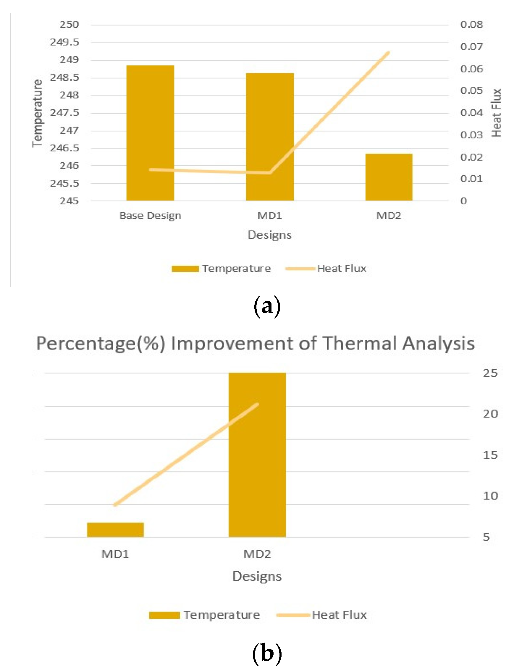
Figure 7a illustrates that the minimum temperature is shown in MD2, though the minimum heat flux is generated in MD1. Figure 7b depicts the percentage % improvement in temperature and heat flux of the Modified Designs compared to the Base Design. From observing the temperature profile, we can infer that the rate of heat transfer in modified designs is higher than the base design. Among all modified designs, MD2(Modified design2) offers the best design option as most parameters such as equivalent stress, deformation, total heat flux has been found to perform better for this specific design (i.e., MD2).
  • (c). Material based analysis for MD2
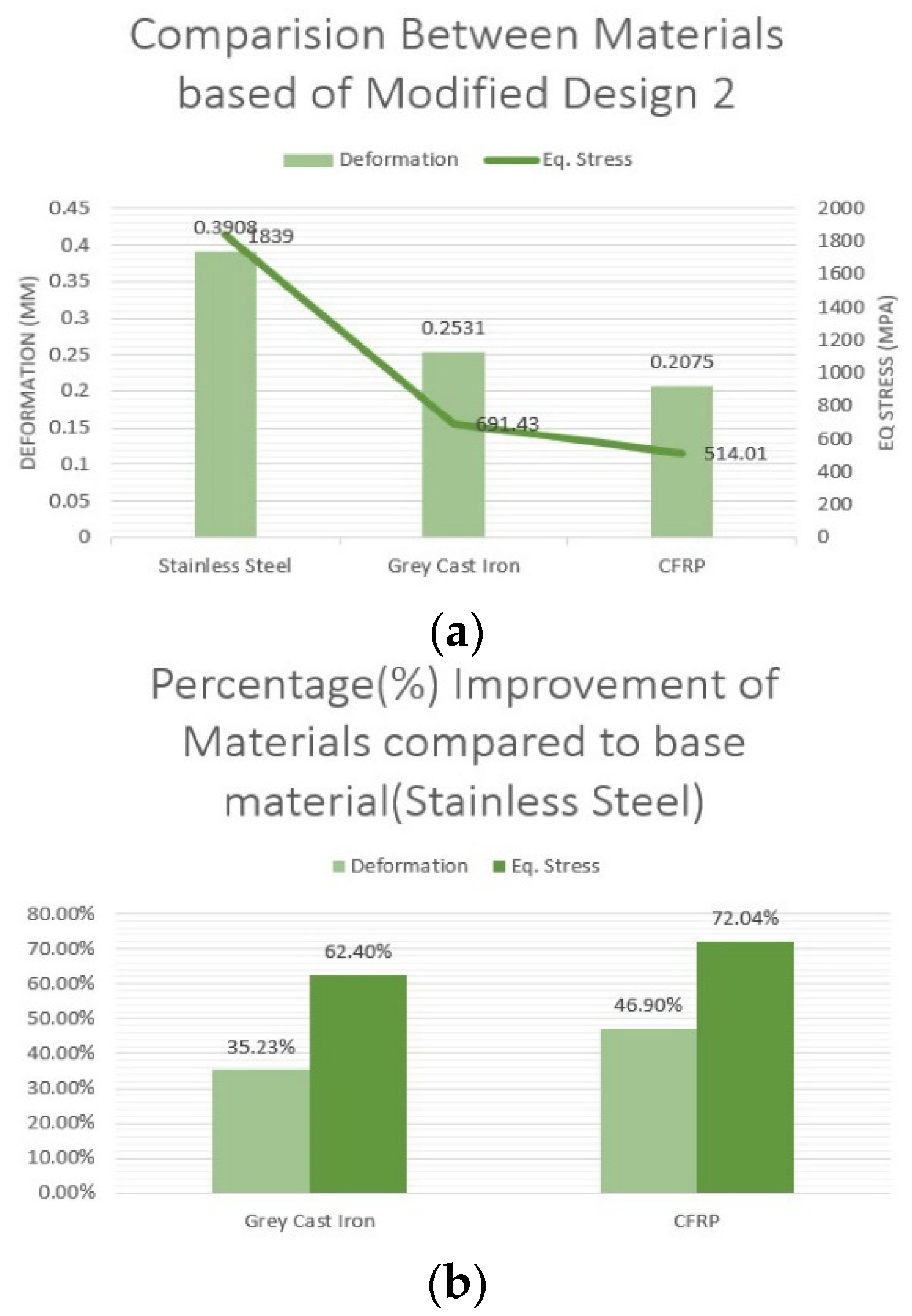
The structural and thermal parameters of MD2 for a few different materials are discussed in the next section. All of the models utilized thus far in this study have been made of stainless steel. As MD2 was determined to perform better than other designs, as was stated in the previous discussions, now we will compare other materials considering MD2 to be constant. For this purpose, grey cast iron and Carbon Fibre Reinforced Polymer (CFRP) materials have been chosen and their properties are listed in Table 2.
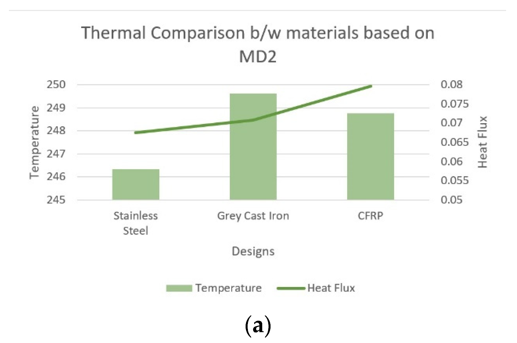
The temperature and heat flux that were created in the design are shown in Figure 9a It is discovered that CFRP material displays the lowest temperature, whilst grey cast iron shows the lowest heat flux compared to stainless steel. Moreover, the largest equivalent stress is created in grey cast iron and the lowest amount of deformation is seen for CFRP material compared to stainless steel, shown in Figure 8a respectively.
Figure 8. (a) Structural characteristics, (b) percentage (%) improvement comparison between materials based on Modified Design 2.
Preprints 76711 g008
Figure 9. Thermal Comparison b/w materials based on Modified Design 2.
Preprints 76711 g009

Conclusion

In this study, steady-state thermal and static structure analysis was conducted for the suggested disc brake rotors Modified Design1(i.e., MD1) & Modified Design2(i.e., MD2), and the properties were compared with those of the reference rotor (i.e., of TVS Apache RTR180) motorcycle. The suggested models were created using a combination of edge cuts, straight slots, vanes, and holes. Numerical simulation and mesh creation were done using the ANSYS platform.
It is seen that the MD2 provide better result in structural analysis with percentage (%) improvement of 12.63% for equivalent stress and 6.05% for deformation, correspondingly. From the thermal analysis, it is found that MD2 provides approx. 25% improvement in temperature and approx. 20% for total heat flux generation. Several materials have been chosen for the modified design MD2, and it has been discovered that cast iron performs better than steel and CFRP laminate, even though the rotor produces less heat when using CFRP laminate. The modified designs exhibit higher performance than the typical disc brake rotor used in TVS Apache RTR180 motorcycle and can produce high braking force while avoiding cracking, buckling, and brake fade under operating conditions, according to the results of the analysis of all the parameters.

Conflicts of Interest

The authors declare that they have no known competing financial interests or personal relationships that could have appeared to influence the work reported in this paper.

References

  1. Agbeleye, A., Esezobor, D., Balogun, S., Agunsoye, J., Solis, J., and Neville, A. (2020). “Tribological properties of aluminium-clay composites for brake disc rotor applications.” Journal of King Saud University-Science, 32(1), 21–28. [CrossRef]
  2. Ahmad, F., Sethi, M., Tripathi, R., et al. (2021). “Thermo-mechanical analysis of disk brake using finite element analysis.” Materials Today: Proceedings, 47, 4316–4321. [CrossRef]
  3. Ghadimi, B., Sajedi, R., and Kowsary, F. (2013). “3d investigation of thermal stresses in a locomotive ventilated brake disc based on a conjugate thermo-fluid coupling boundary conditions.” International communications in heat and mass transfer, 49, 104–109. [CrossRef]
  4. Jafari, R. and Akyuz, R. (2022). “Optimization and thermal analysis of radial ventilated brake disc to enhance the cooling performance.” Case Studies in Thermal Engineering, 30, 101731. [CrossRef]
  5. Jian, Q., Wang, L., and Shui, Y. (2020). “Thermal analysis of ventilated brake disc based on heat transfer enhancement of heat pipe.” International Journal of Thermal Sciences, 155, 106356. [CrossRef]
  6. McPhee, A. D. and Johnson, D. A. (2008). “Experimental heat transfer and flow analysis of a vented brake rotor.” International Journal of Thermal Sciences, 47(4), 458–467. [CrossRef]
  7. Ozkan, D., Gok, M. S., and Karaoglanli, A. C. (2020). “Carbon fiber reinforced polymer (cfrp) composite materials, their characteristic properties, industrial application areas and their machinability.” Engineering Design Applications III, Springer, 235–253.
  8. Parab, V., Naik, K., and Dhale, A. (2014). “Structural and thermal analysis of brake disc.” International Journal of Engineering Development and Research, 2(2), 1398–1403.
  9. Pinca-Bretotean, C., Bhandari, R., Sharma, C., Dhakad, S. K., Cosmin, P., and Sharma, A. K. (2021). “An investigation of thermal behaviour of brake disk pad assembly with ansys.” Materials Today: Proceedings, 47, 2322–2328. [CrossRef]
  10. Sathishkumar, S., Jeevarathinam, A., Sathishkumar, K., Kumar, K. G., et al. (2022). “Temperature dissipation and thermal expansion of automotive brake disc by using different materials.” Materials Today: Proceedings, 49, 3705–3710. [CrossRef]
  11. T.V. Manjunath, P.M. Suresh, Structural and thermal analysis of rotor disc of disc brake, Int. J. Innov. Res. Sci. Eng. Technol. 2 (2013) 2319–8753.
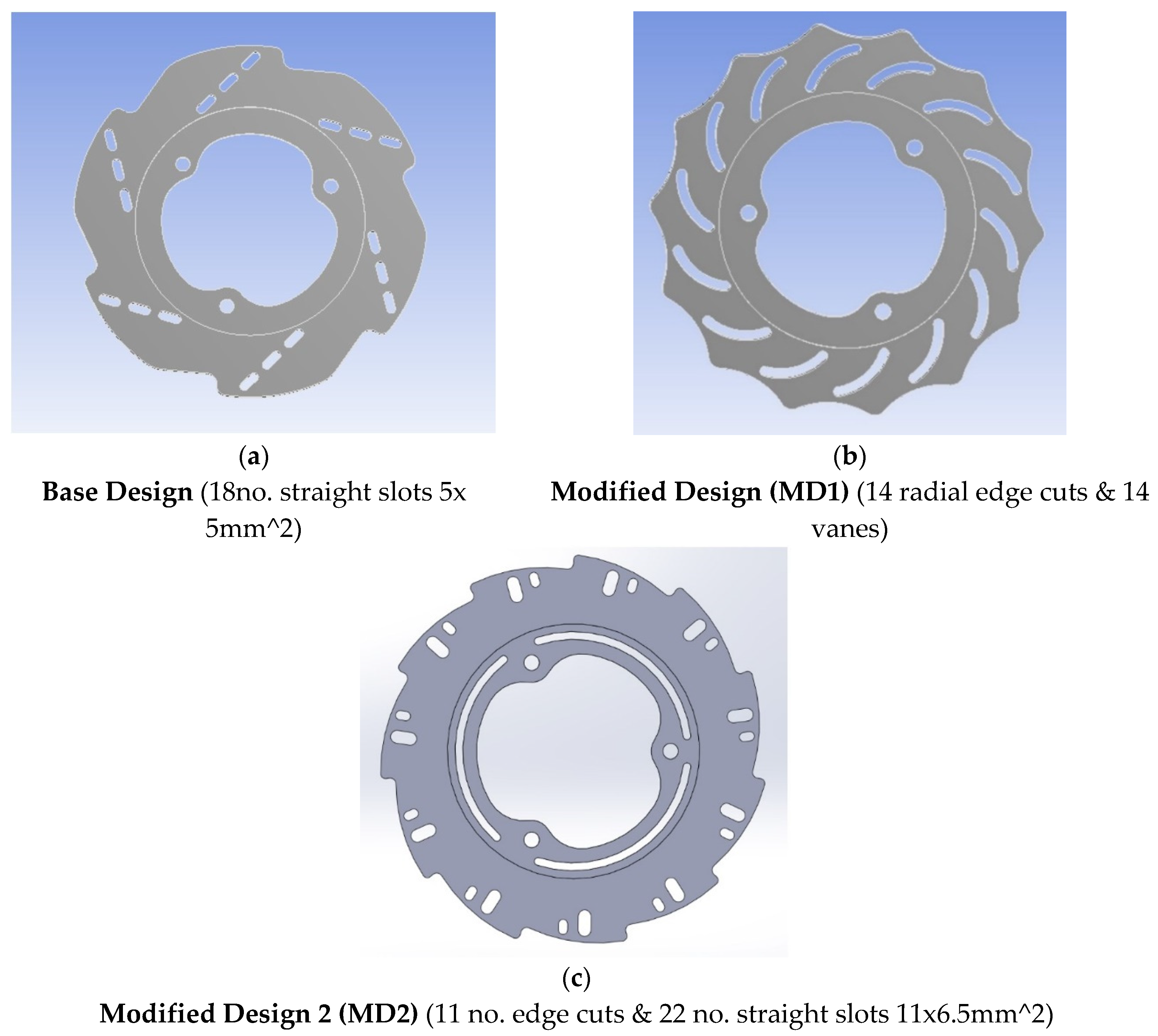
Figure 1. (a) Base Model; (b) Modified Design 1; (c) Modified Design 2.
Preprints 76711 g001
Figure 2. Visualization of the deformation (mm) of (a) Base Design, (b) Modified Design 1 (MD1), (c) Modified Design 2 (MD2).
Preprints 76711 g002
Figure 3. Visualization of equivalent (von-Mises) stress (MPa) of (a) Base Design, (b) Modified Design 1 (MD1), (c) Modified Design 2 (MD2).
Preprints 76711 g003
Figure 4. (a) Structural characteristics, (b) percentage (%) improvement of structural characteristics.
Preprints 76711 g004
Figure 5. Temperature distribution of (a)Base Design, (b)Modified Design 1 (MD1), (c)Modified Design 2 (MD2).
Preprints 76711 g005
Figure 6. Heat flux distribution of (a)Base Design, (b)Modified Design 1 (MD1), (c)Modified Design 2 (MD2).
Preprints 76711 g006
Figure 7. (a) Thermal characteristics, (b) percentage (%) improvement of thermal characteristics for various models.
Preprints 76711 g007
Table 1. General features used to generate the model.
Feature
Outer Diameter 200mm
Inner Diameter 150mm
Thickness 3.5mm
Brake pad surface (area) 3848.22mm^2
Wheel hub support 3
Material (yield strength) Stainless steel 207MPa
Co-efficient of friction 0.5
Maximum pressure applied 1MPa
Table 2. Material properties used to develop Modified Design 2.
Properties Grey Cast Iron CFRP
Tensile Strength (MPa) 412.7 414
Poisson’s Ratio 0.3 0.3
Mass Density(kg/m^3) 1800 7200
Disclaimer/Publisher’s Note: The statements, opinions and data contained in all publications are solely those of the individual author(s) and contributor(s) and not of MDPI and/or the editor(s). MDPI and/or the editor(s) disclaim responsibility for any injury to people or property resulting from any ideas, methods, instructions or products referred to in the content.
Copyright: This open access article is published under a Creative Commons CC BY 4.0 license, which permit the free download, distribution, and reuse, provided that the author and preprint are cited in any reuse.
Prerpints.org logo

Preprints.org is a free preprint server supported by MDPI in Basel, Switzerland.

Subscribe

© 2024 MDPI (Basel, Switzerland) unless otherwise stated