1. Introduction
Magnetorheological fluids are intelligent smart materials that are controllable, adjustable and vary their rheological properties (elasticity, viscosity, or plasticity) on the application of a magnetic field supplied by the coil current. These fluids can also exhibit fast, strong, and reversible changes [
1]. MR fluids are suspensions of miniature particles, made up of carbonyl iron or powdered iron or iron-cobalt alloy that are transformed into a solid gel and will line up to form chain-like structures in the direction of the magnetic flux paths in a few milliseconds when the magnetic field is applied [
2]. MR fluids have characteristic properties that enable a quick response time and stiffness, which are directly proportional to the applied magnetic field and also can achieve a wide range of apparent viscosity which is controllable since the strength of the magnetic field can be varied with the help of an input current to the electromagnet [
3,
4]. MR fluid holds great potential in electromechanical interfaces such as brakes, where the operative function was in a direct-shear mode. These smart fluids are confined in a small gap between a rotor and a stator which are perpendicular to the rotational axis [
5]. The magnetic field lines are radially directed to penetrate through the MR fluid gap to generate controllable shear stress that causes friction on the rotating disk surfaces, thus generating a retarding torque [
6]. Priority to ensuring MRB rapid response a wide range of research since decades are carried out by many researchers to enhance output braking torque when the increased magnetic field is limited to magnetic saturation in the working area of the fluid.
The magnetorheological brake was initially designed in 2003 by W. H. Li and H. Du with a single disc configuration model indicated a progressive increase in brake torque with an increase in magnetic field strength [
7]. The torque produced in a disc-type brake depends on various parameters such as disc radius, disc thickness and composition of MR fluid. These parameters affect the shear stress generated that sources friction in the surfaces of the rotating disk while braking due to the change in viscosity under the applied magnetic field [
8]. A dual disc design was proposed to achieve a high torque density when fluid was inserted between the rotating and fixed discs. Attia et. al studies reveal that MR fluid gains fast braking responses due to exerted shear force acting perpendicularly on the dual rotating discs [
9]. Daoming et.al experimented and proved that the multidisc concept can satisfy the requirement of maximum braking torque by showing a good linear relationship under the condition of magnetic saturation [
10]. Further, these studies were extended to the single pole multiple discs concept in which a model proposed by Huang et. al exhibits advantages of rapid response, magnetic medium characteristics and arrangement structure of the magnetic flux flow [
11].
To increase the active area of the MR fluid, the multiple electromagnetic poles concept was introduced in MR brakes after a single electromagnetic pole has reached the limits of torque enhancement due to the restriction of the magnetic field strength. In 2013, Shiao et al. proposed this novel design and outcomes that explain the increased magnetic flux flow through pole heads [
12]. Later on, Shiao et. al introduced a model of six electromagnetic poles with bilayer MR fluid by merging concepts of the multi-pole and multi-layered to study the magnetic field superposition influence on the braking torque and this study revealed that due to geometric dimensional parameters at each pole head the working area of the fluid increases and exhibits great enhancement of the braking torque and TVR [
13]. Wu et. al studied the multi-pole and dual-gap magnetorheological brake to find the impact of individual input currents on the active energizing surface areas on the rotor disk where the concentrated magnetic flux is generated [
14,
15].
Axial and radial magnetic flux can influence the braking output torque by increasing either axial length or radial dimension of the rotating disc. Shiao et.al explained that by varying pole head radial distance the flow of magnetic flux increased effectively and improves the brake performance [
16]. Structured models of brakes such as single-disk, dual disk, drum and hybrid types by maximizing the braking torque with the torque ratio higher than desired and by minimizing the mass of the brake were carried out by Zhou et. Al [
17]. With the compactness of the magnetorheological brake to obtain the maximum braking torque, Shiao et al. proposed a design with a small radial dimension that results in a large torque transmission capacity [
18]. Magnets with varying shapes, coil windings gaps and shank dimensions can influence the magnetic flux captured by the stator [
19]. In addition to the compact design Song et. al studied the impact of shaft dimensions that intensify more efficient areas of magnetic flux across the MR fluid [
20]. Li et. al discussed the new concept of axial flux in permanent magnets which are mechanically activated to determine the magnetic field distribution at the midpoint of the shank and Binyet et al. proposed a modification with built-in permanent magnets that increases the internal magnetic field intensity [
21].
Nguyen et. al studied the effect of shapes of the brake envelope such as rectangular, pentagonal and spline shapes to understand the flux flow [
22]. Sheth et. al investigated special geometric shapes to the pole heads to gain the maximum torque and also investigated the effect of these pole shapes on the motor [
23]. Mehmet et. al explained that different geometric shapes of the pole heads show an impact on motor performance [
24]. None of the studies were focused till now on the effect of magnetic pole head geometry on an MR brake performance. Therefore, this work focuses on investigating the influence of pole geometries such as the shape, area, radial position of the pole head and corresponding shank dimensions on the MR brake torque. Conventional pole heads such as circle or square have to be changed with trapezoid, pentagon and hexagonal pole head profiles to increase the working area of the brake. The Ellipse pole head profile covers the maximum radial distance on the surface of the brake with a larger pole head area. These shapes also influence the flow of magnetic flux that simultaneously affect the braking torque.
2. Concept of the MR brake
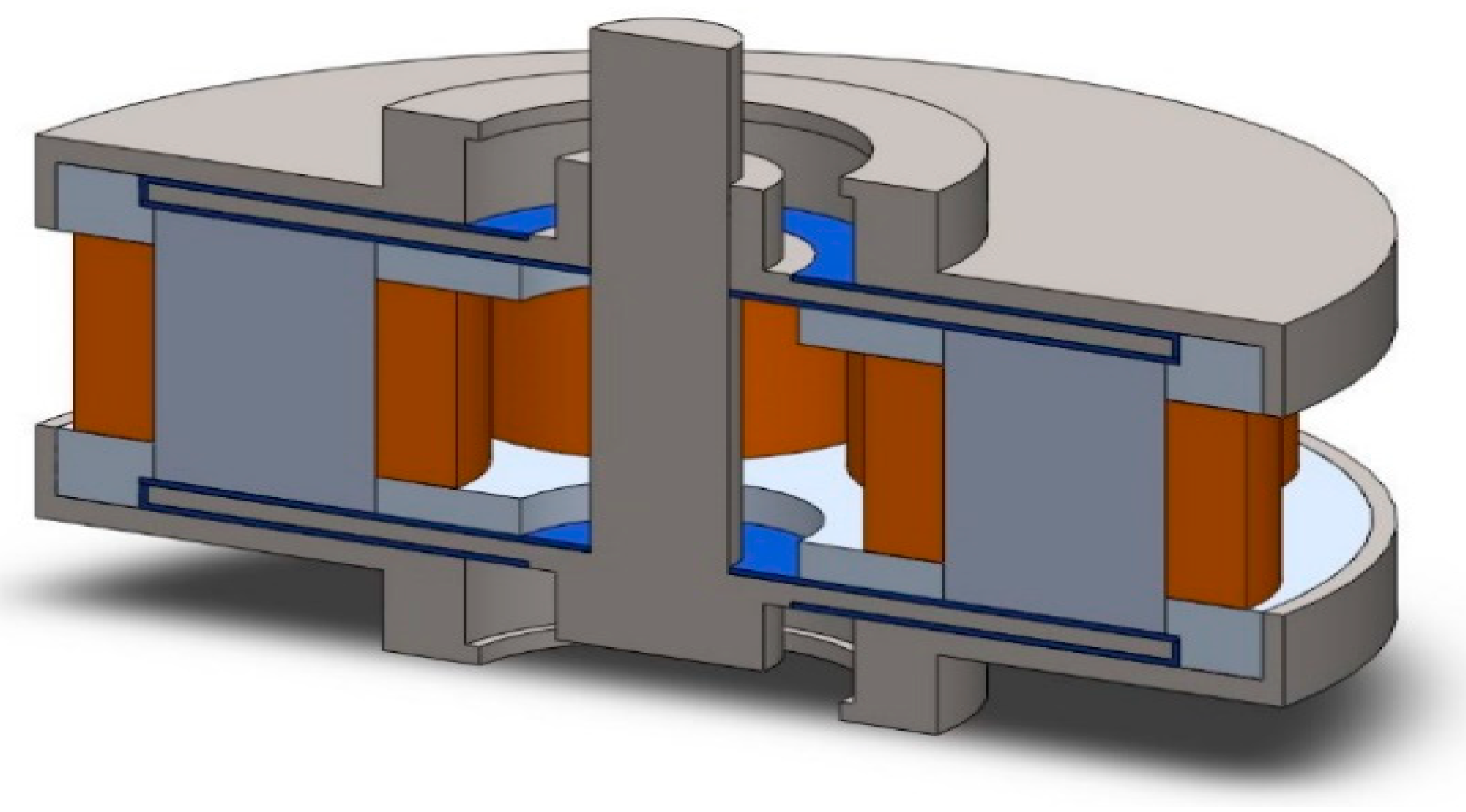
A magnetorheological brake that has a symmetrical structure with a dual disc configuration comprising four magnetorheological fluid layers and six magnetic poles as shown in
Figure 1. The main components include stator cases, rotor discs, pole heads, fluid layers, shank /core, stator caps, and outer covers. Optimizing the geometry based on the parameters referred to in
Table 1, influences the output torque. The materials of the components have to be selected based on thermal, structural and magnetic properties.
The working concept of MR brake is that a larger working area of fluid results in a higher total braking torque due to increased shear stress in the MR fluid. The larger working area of the MR fluid is dependent on the pole head area helpful to generate larger magnetic flux. However, a larger pole head area reduces the coil-winding space and also makes magnetic flux might bypass from one pole to its adjacent pole via the MRF. The non-magnetic stator case was designed for the insertion of magnetic poles in a circular array with an alloy of aluminum.
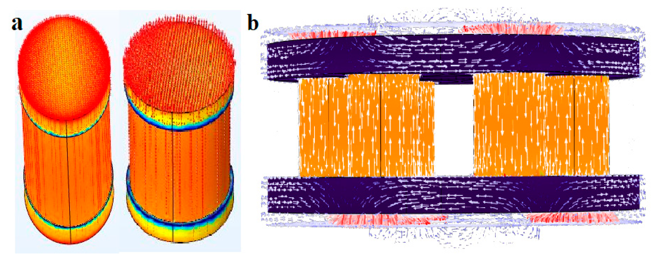
Six magnetic poles with magnetically permeable cylindrical cores/shanks as shown in
Figure 2 (a) were used to create the multi-pole magnetic field. Magnetic cores contain pole heads that are inserted into the holes of the stator case and shank that give the flux cycle between two adjacent cores as shown in
Figure 2 (b). A higher poles MR brake does not always get higher brake torque because the gap between the two pole heads is too close then the available winding space between poles decreases with the increased number of poles. Magnetically permeable rotor discs were placed parallel to the surface of the stator cases and pole heads.
3. Pole Head Geometry
The pole head geometry should be improved to obtain maximum shear stress which helps in increased braking torque. The magnetic field induced by the coil winding flows through the shank and reaches the pole head assembled inside the nonmagnetic stator case in the form of flux lines. The pole head may be divided into three regions: the central region, where the pole is responsible to pass the maximum flux; the high field region, where the pole head experiences the maximum flux flow after the central region. The low field region occurs at the edges of the poles where the flux flow is less. A smaller magnetic field allows the flow to drop more rapidly at the edge of the pole heads.
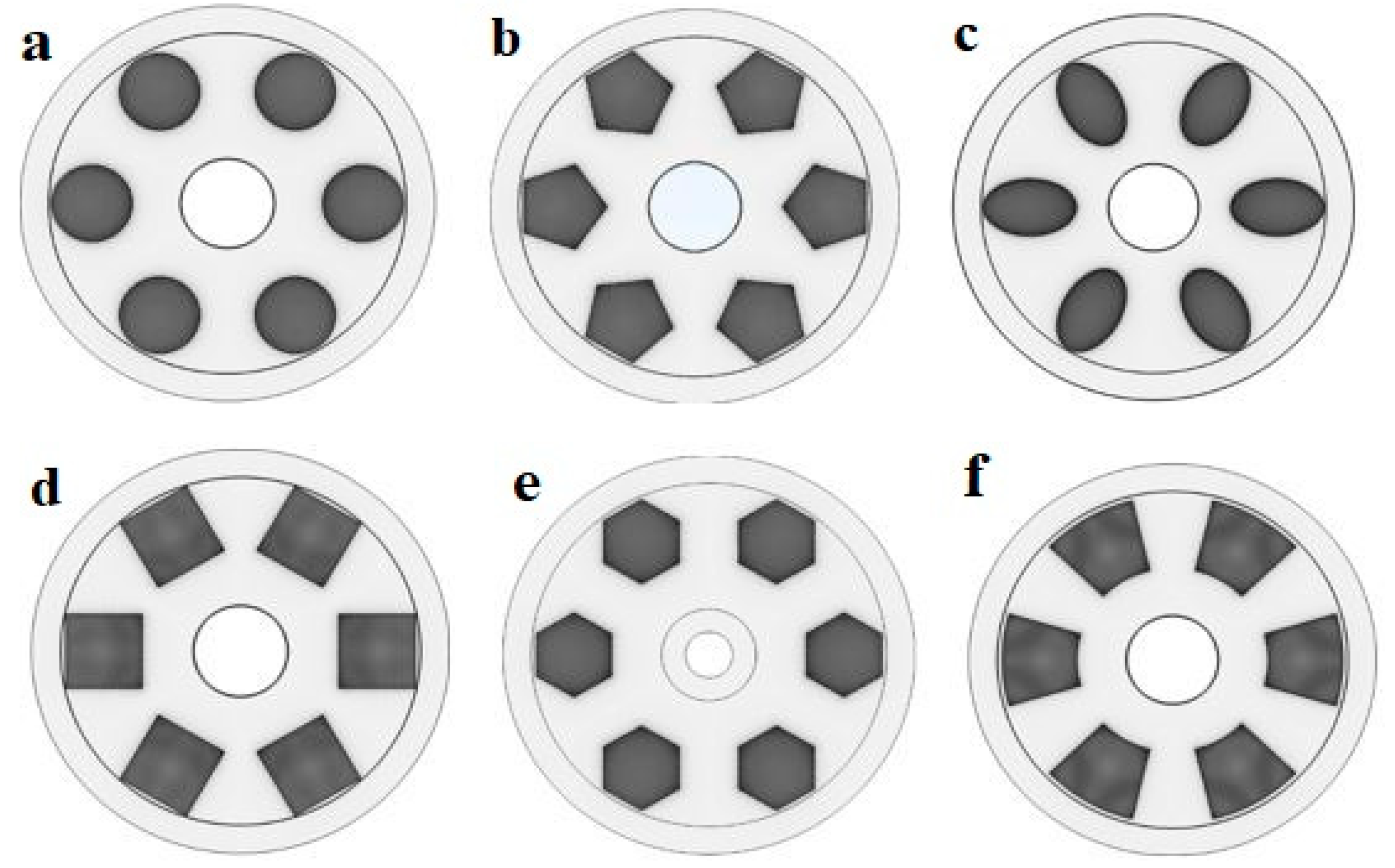
Pole head profiles have to be changed appropriately to enhance the braking torque in the compact magnetorheological brake configuration. The effective working area of MR fluid depends on the pole head area, if the area increases then shear stress developed in MR fluid increases resulting in higher braking torque. So square and trapezoid pole head shapes are considered in this study for larger pole head areas. Magnetic flux flow is another factor that is influenced by the pole head area. If the gap between poles is smaller, the flux flow from one pole to the adjacent pole might bypass. Considering this aspect the hexagon and pentagon pole head shapes with larger areas are arranged symmetrically linear. The radial distance between the centers of the pole to the center of the brake affects the final torque. An ellipse pole head profile is considered to achieve a larger radial distance and also more gap between the poles. To obtain higher torque and also to overcome this bypass of flux flow in this compact design, different geometric pole head profiles as shown in
Figure 3, such as square, trapezoid, pentagon, ellipse, hexagon and circle were analyzed.
For the simulation study, electromagnetic analysis is carried out to calculate the amount of magnetic field generated. It is a flexible platform that allows users to model all relevant physical aspects of any type of design and is used to support the optimization process of torque enhancement. In this analysis, the resulting magnetic field intensity distribution within the magneto rheological brake configuration is analyzed.
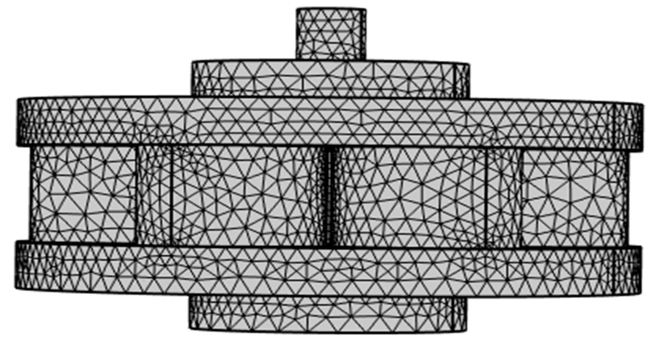
The magnetic property, namely the B-H curve was created to assign the MR fluid. The simulation was performed with various numbers of turns in a coil and also by varying the current. The load in the present problem is the current flowing through the coil, responsible for the magnetic flux. After the mesh was generated as shown in
Figure 4, the FEM was solved using a parametric nonlinear solver and the magnetic field distribution onto the MR fluid. Once the results of magnetic field distribution are known, the shear stress value can be obtained.
4. Initial validation of the results
Multi-pole magnetorheological brake proposed three-dimensional computer model was validated against the experimental results of the optimized MRB presented previously by Shiao et.al [
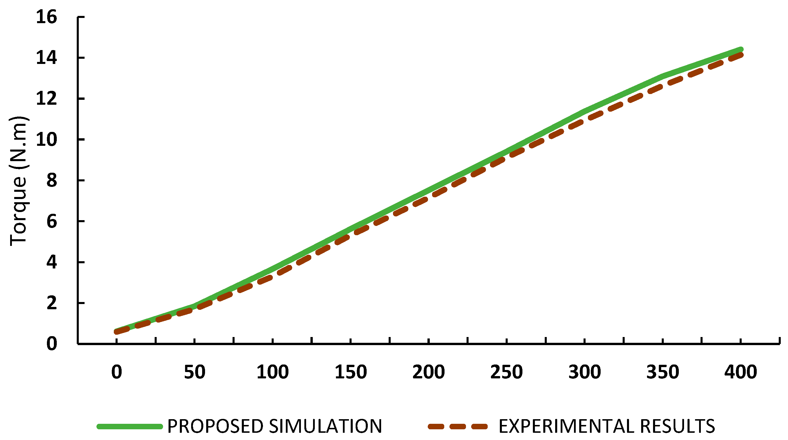
25]. To compare the performance of the proposed MR brake, the relation between braking torque and the number of turns of the core winding at different input currents was studied. The optimized dimensions of the brake were set accordingly. The number of poles is 6, and the gap between the centers of the poles was set to 28.25mm, 3mm pole head thickness, the radii of pole head radius and shank radius are 8.5mm and 8.0 mm respectively.
Brake torque increases gradually to the maximum by increasing the input current from 0 to 2 Amp. Overall the experimental results were comparatively similar to the simulation results of the proposed model, whereas the graph as shown in
Figure 5, has slightly lower values in simulation. The difference observed is due to the viscosity as well as the friction, which is not accurately accounted for in the simulation model.
Hence, the results are similar comparatively so this research can be further investigated on different pole head geometries to understand the effect on brake torque. So these results prove that the proposed pole head shapes. Hence, the results of validation prove that the proposed pole head geometry variation in an MR brake can be investigated for further analysis.
5. Results
Simulation results of the magnetic flux density of a magnetorheological Brake were analyzed. Considering the optimized brake parameters range, the present study on varied pole head geometries observes the effect on braking torque. The simulation process for different types of pole head profiles majorly focuses on the best value of pole head radius (varied from 7.5 mm to 8.5 mm), shank dimensions (varied from 7.0 mm to 8.0 mm) and the number of wire turns in the coil (240 -290 turns) that reflect on output shear force.
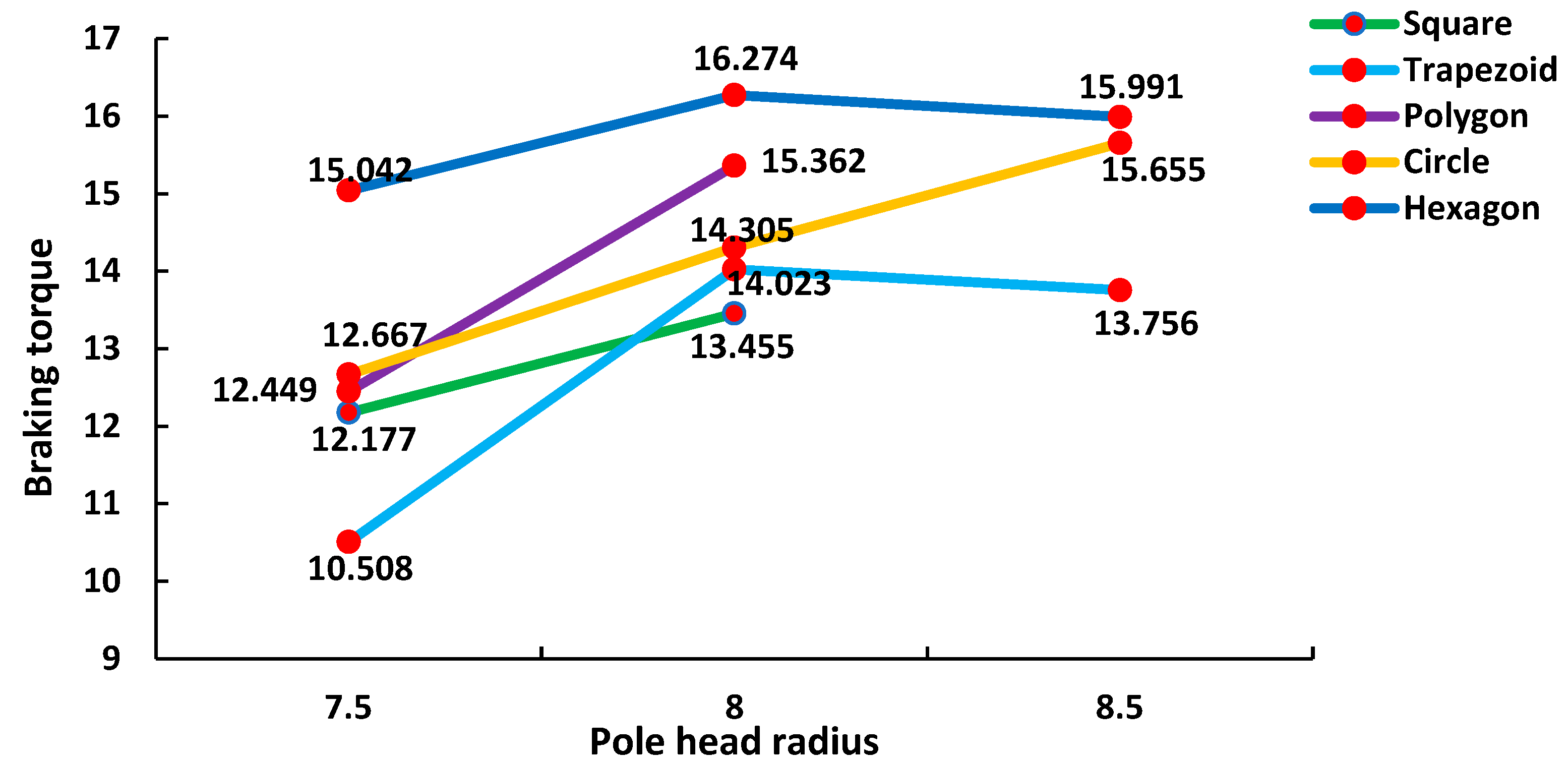
As shown in
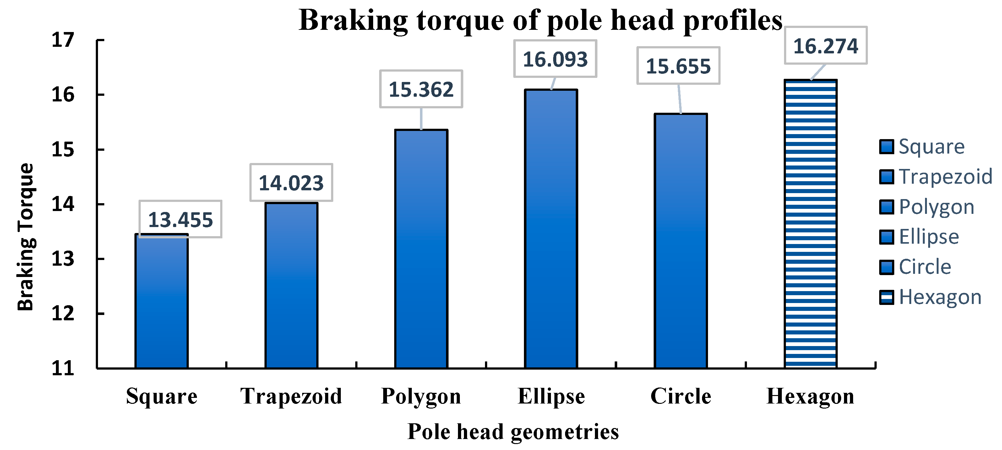
Figure 6 the braking torque for all pole head profiles at 270 number of wire turns and center of pole radii 28.5 mm are discussed. The circle profile obtained the best output value of 15.655 N-m at an 8.5 mm pole head radius and 8.0 mm shank radius. The trapezoid profile obtained the best output value of 14.023 N-m at an 8.0 mm pole head radius and 8.0 mm shank radius. The square profile obtained the best output value of 13.455 N-m at an 8.0 mm pole head radius and 8.0 mm shank radius. The pentagon profile obtained the best output value of 15.362 N-m at an 8.0 mm pole head radius and 8.0 mm shank radius. The hexagon profile obtained the best output value of 16.274 N-m at an 8.0 mm pole head radius and 8.0 mm shank radius. In the ellipse profile due to its shape the possible pole head radius is 6.3 mm, the shank radius is 6.5 mm, the center of the pole radius is 27 mm and the output braking torque value is 16.093 N-m. Therefore, the obtained results for different pole head profiles were influenced based on different parameters such as effective area of MR fluid, maximum magnetic flux flow, radial dimensions and shank radius.
5.1. Effective Area of MR fluid
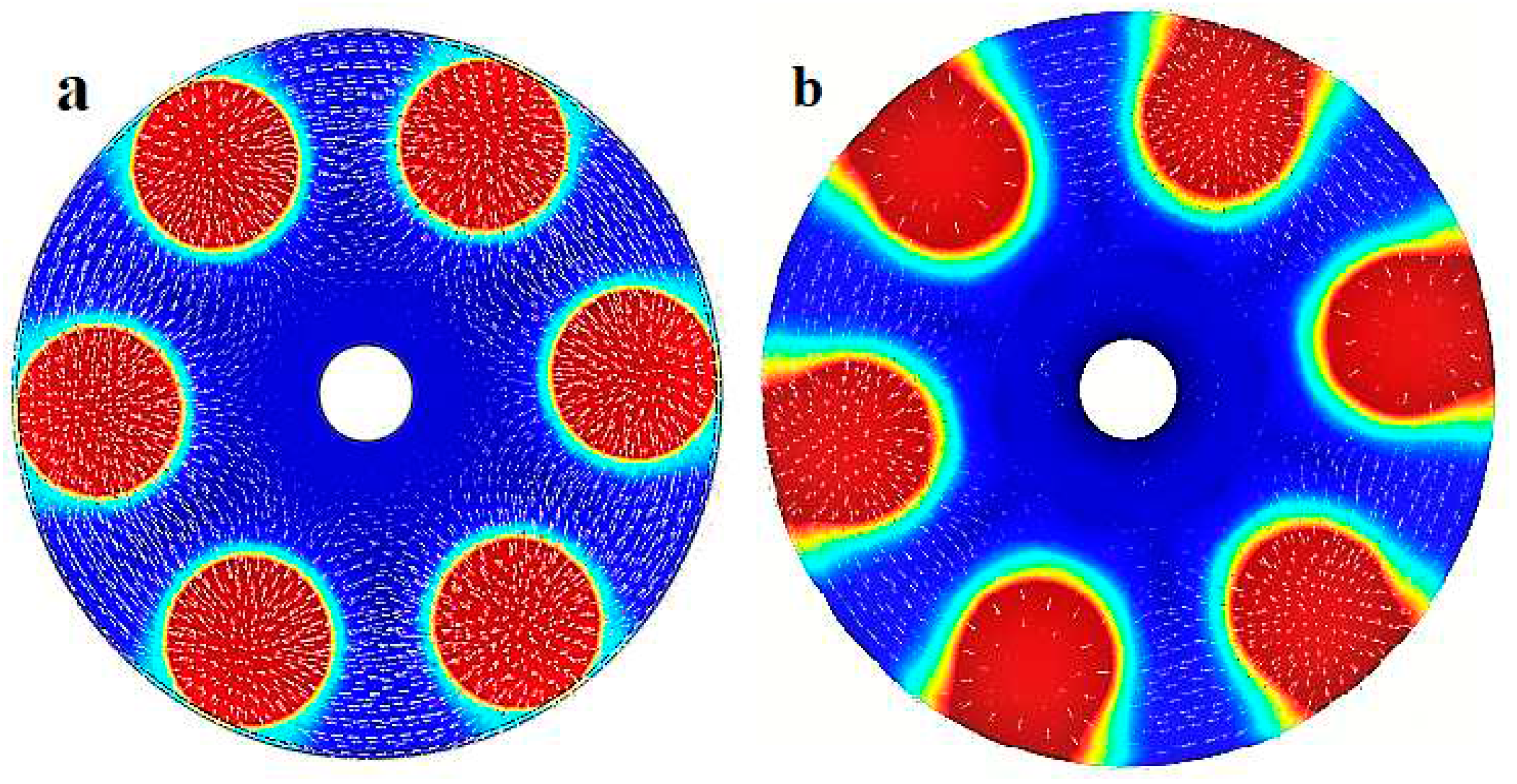
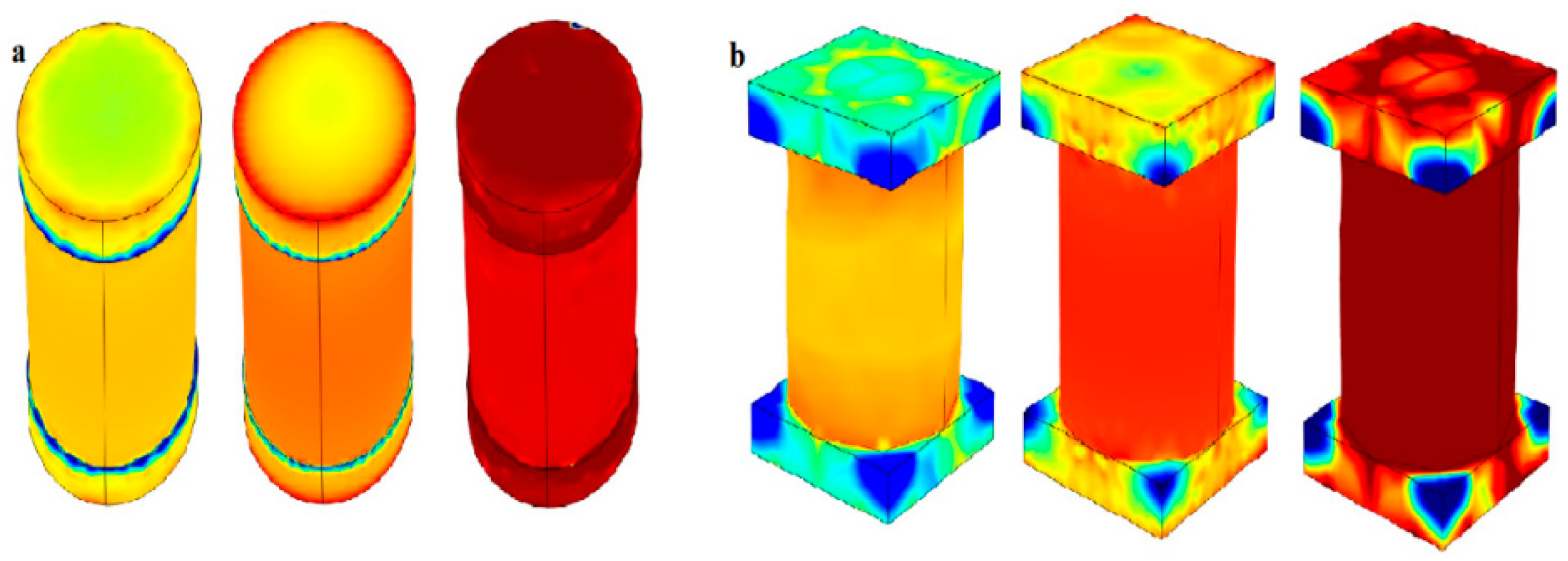
Shear stress developed in the MR fluid depends on the pole head area.The maximum yield shear stress of the fluid is in the controllable active state and it increased on the disc surface simultaneously increasing the braking torque. Inner layers of a brake as shown in
Figure 7 (a) have higher stress which results in increased magnetic field strength and when it passes through the rotor and reaches the outer layer in
Figure 7 (b), the stress is quite less and also flux disperses to the surroundings as shown in the figure. From the upshots of this study, hexagonal pole head benefits higher yield stress compared to other pole head configurations.
5.2. Maximum Magnetic Flux Flow
Poles are the main source of magnetic flux generated at the MRF effective area which is between the core and rotor disk surface. At the pole head surface area, produced magnetic flux will penetrate orthogonally across the circular disc surface and the stator which results in creating a yield resistance to produce field torque for the brake. Magnetic flow is in the form of a loop from one pole to the adjacent pole through the MR gap, stator and then revert through the MR gap to the adjacent pole. To Increase this flux it requires more poles but the pole radius has to be reduced due to compactness.
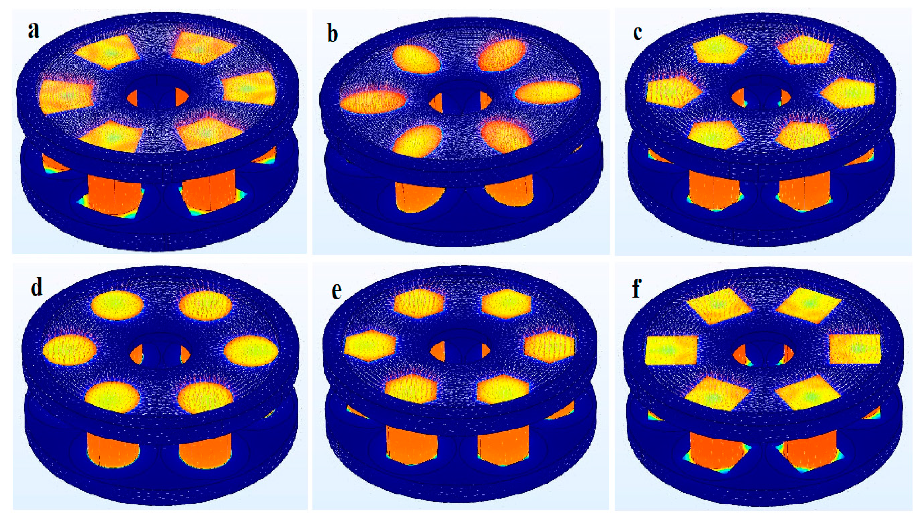
As shown in
Figure 8, observations of this study for all pole head profiles explain that at different pole head radii, the density of the flux is distributed equally indicated by the colour contours. The red colour arrows on the pole head area indicate the flux concentration. Higher density flux occurs at the middle distance between the two effective areas. The gaps between those magnetic coils were optimized to prevent magnetic flux leakages as well as to avoid magnetic saturation. It can be seen that the density of the flux is distributed equally and the white color occurs on the sides of a pole indicating the effective area that indicates the flux concentration transferring to the adjacent pole. The 90
o corner angle of the square reduces the flux flow due to its shape configuration, the distance between the center of the pole head area and the vertex is high so the concentration of flux varies. The major drawback of using the circle pole head profile is that the shank radius and pole head radius cannot be of the same dimension. The ellipse pole head shape is similar to a circle shape but it is placed in the radial direction. It is also feasible for manufacturing and also able to flow the maximum flux comparatively higher than other profiles. At the 120
o higher corner angle of the hexagonal shape, the flux flow can travel in more directions from the 6 vertices. The trapezoid pole head shape assembled in the MRB obtained lesser braking due to its configuration. The distance between the center of the shank and the edges of the pole head is more, so in this area the flow of flux is less which simultaneously affects the torque.
5.3. Effect of Coil/Shank shape and radius
The brake performance is directly affected by the resistance of the coil based on parameters such as the number of wire turns, applied current and the coil/shank dimensions. Increasing the number of wire turns and input current influences the yield stress and also the saturation limits depend on the magnitude of yield shear stress. An approximate number of wire turns is anticipated by the quotient of the coil area and the axial width of the coil. The greater axial width of the coil yields a greater number of turns and thus achieves a higher braking torque. The wire is to be wound precisely so that each strand effectively occupies a total cross-sectional area which improves the braking torque. Torque increment is extremely low once the selected coil material reaches the magnetic saturation point.
Ellipse pole head geometry was designed with an elliptical shank to gain higher yield stress and for all other geometries, a circular coil was used to analyze. Shank radii varied from 6.5 mm to 8.5 mm and the pole head radii based on the saturation condition preferred from 7.0 to 8.0 mm, number of wire turns are calculated based on the axial width of the coil, a gauge of the wire was 0.57mm at a constant applied current of 2 amperes. From the
Figure 9, we can observe the three magnetic conditions of the elliptical and circular coils. The higher braking performance was obtained at an optimum saturation condition of the coil at 8.0mm shank radii for square, trapezoid, circle, pentagon and hexagonal pole heads and ellipse at 6.5 mm shank radii.
5.4. Effect of Radial Geometric Dimension
Magnetorheological brake utilizes both axial and radial magnetic flux to generate the braking torque. The rotor of the brake in the proposed work is a dual disc configuration and the MR fluid acts the force on the disc in a shear mode. In this disc brake, the torque will be easily affected by the centrifugal force in a superficial direction. Especially radial dimensions affect the magnetic field that acts on the disc surface and a very less magnetic field exerted axially to both sides of the rotor. Besides, the torque enhancement can be achieved by increasing either the axial or the radial dimensions of the rotor. The extended rotor’s radial dimensions create a greater active area of the fluid, thus producing higher shear stress, subsequently a higher braking torque.
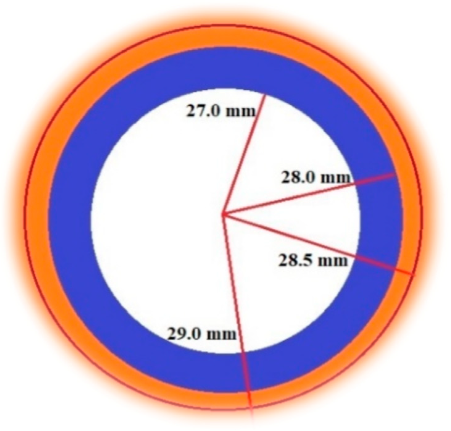
Design configurations for different pole head geometries varied due to the compactness of the brake. Analysis for each pole head shape was done from 26.5 mm to 29.0 mm, which is the maximum radial width to the midpoint of pole heads. As shown in
Figure 10, only for ellipse pole head geometry the obtained torque is at maximum radial width of 27.0 mm and for all other configurations 28.5 mm results in the higher braking torque. At a higher radial dimension of 29.0 mm, the torque slightly decreases due to the active chain area of MR fluid penetrating the magnetic flux to the outward direction of the brake.
5.5. Comparison of various pole head profiles for obtained braking torque
Comparing various pole head profiles to the shear force value obtained evaluates its higher and more effective braking torque. Here based on the observations, the higher braking torque was obtained for hexagonal pole head geometry and lower for square pole head geometry. An increment of 20.89% for braking torque performance is obtained. The simulation results of a multi-pole dual disc design show the advantage of making it a high-yield area that gives a high shear force. For different pole head geometries, electromagnetic analysis was done to prevent the occurrence of magnetic saturation near the coil and it can be seen that the magnetic flow direction in all the pole head profiles is tangible as a loop from one pole through the MR gap across the rotor. It is also noteworthy that the elliptical shape shank where the core winding can be wound directly is also convenient in manufacturing. The torque increases nearly linearly with the rise of the number of turns (N) and applied current (I), significantly determining the magnitude of the magnetic field strength.
The square pole head geometry obtained 13.455 N-m, the circle pole head profile obtained 15.655 N-m, the pentagon pole head profile obtained 15.362 N-m, the ellipse pole head profile obtained 16.093 N-m, the trapezoid pole head profile obtained 14.023 N-m. Comparing all the varied pole head profiles the output braking torque is depicted in
Figure 11, that a larger corner angle (hexagon) can produce a high magnetic flux density that helps in torque improvement. The obtained braking torque is 16.272 N-m for a hexagonal profile which is an increment when compared with other pole head geometries.
6. Conclusions
This research paper has reported the electromagnetic simulation outcomes on compact multi-pole dual disc magnetorheological brake by varying pole head profiles. From the analysis, it can be concluded that the pole head area impacts the MR fluid surface resulting in an enhancement of the shear stress. The magnetic flux flow for all the pole head profiles gives a good correlation to the torque generated. Six different pole head geometries (pentagon, square, hexagonal, circle, ellipse and trapezoid), wherein the hexagon profile results in a high shear force value and square profile output the least. An increment of 3.88% for braking torque performance is obtained at the hexagonal pole head profile and the braking torque is significantly enhanced.
Acknowledgments
This research was financially supported by Ministry of Science and Technology, Taiwan (project no.: MOST 109-2221-E-027-048).
References
- Esmaeilnezhad, E.; Choi, H.J.; Schaffie, M.; Gholizadeh; Ranjbar, M.; Kwon, S.H. Rheological Analysis of Magnetite Added Carbonyl Iron-Based Magnetorheological Fluid. Journal of Magnetism and Magnetic Materials 2017, 444, 161–167. [Google Scholar] [CrossRef]
- Wang, D.; Zi, B.; Zeng, Y.; Hou, Y.; Meng, Q. Temperature Dependent Material Properties of The Components of Magnetorheological Fluids. Journal of Materials Science 2014, 49, 8459–8470. [Google Scholar] [CrossRef]
- Olabi, A.; Grunwald, A. Design and Application of Magnetorheological Fluid. Materials & Design journal 2007, 28, 2658–2664. [Google Scholar]
- Bossis, G.; Lacis, S.; Meunier, A.; Volkova, O. Magnetorheological Fluids. Journal of Magnetism and Magnetic Materials 2002, 252, 224–228. [Google Scholar] [CrossRef]
- Jolly, M.R.; Bender, J.W.; Carlson, J.D. Properties and Applications of Commercial Magnetorheological Fluids. Journal of intelligent material systems and structures 1999, 10, 5–13. [Google Scholar] [CrossRef]
- Park, E.J.; Da Luz, L.F.; Suleman, A. Multidisciplinary Design Optimization of an Automotive Magnetorheological Brake Design. Compute structures journal 2008, 86, 207–216. [Google Scholar] [CrossRef]
- Li, W.H.; Du, H. Design and Experimental Evaluation of a Magnetorheological Brake. International Journal of Advance Manufacturing Technology 2003, 21, 508–515. [Google Scholar] [CrossRef]
- Luckachan George, K.; Tamilarasan, N.; Thirumalai. Design and analysis of magneto rheological fluid brake for an all-terrain vehicle. Materials science and engineering 2018, 310, 012127. [Google Scholar]
- Attia, E.M.; Elsodany, N.M.; El-Gamal, H.A.; Elgohary, M.A. Theoretical and Experimental Study of a Magnetorheological Fluid Disc Brake. Alexandria engineering journal 2017, 56, 189–200. [Google Scholar] [CrossRef]
- Daoming wang; Lan Yao; Biao Wang. Design, Analysis and Electromagnetic Simulation of a Multi-Disc Automotive Magnetorheological Brake. IEEE, J. mechatronics 2018, 1, 112–116. [Google Scholar]
- Huang, J.; Zhang, J.Q.; Yang, Y.; Wei, Y.Q. Analysis and Design of a Cylindrical Magnetorheological Fluid Brake. Journal of materials processing technology 2002, 129, 559–562. [Google Scholar] [CrossRef]
- Shiao, Y.; Nguyen, Q.A. Development of a Multi-Pole Magnetorheological Brake. Smart material Structures 2013, 22, 065008. [Google Scholar] [CrossRef]
- Shiao, Y.; Ngoc, N.A.; Lai, C.H. Optimal Design of a New Multipole Bilayer Magnetorheological Brake. Smart material Structures 2016, 25, 115015. [Google Scholar] [CrossRef]
- Jie; xuezheng, Jiang; Jin, Yao; Hua li, Zhao, C. L. Design and Modeling of a Multi-Pole And Dual-Gap Magnetorheological Brake With Individual Currents. Advances in mechanical engineering 2016, 8, 1–15. [Google Scholar]
- Ubaidillah, A.N.S.; Permata, A.; Wibowo, E.P.; Budiana, I.; Yahya; Mazlan, S.A. Magnetostatic Simulation on a Novel Design of Axially Multi-Coiled Magnetorheological Brakes. Sustainable energy and advanced materials 2016, 050005, 1–7. [Google Scholar]
- Shiao, Y.; Nguyen, Q.A.; Zhengyang, Z. Design and experiment of a new magnetorheological brake. International journal of applied electromagnetics 2015, 48, 309–326. [Google Scholar] [CrossRef]
- Zhou, W.; Chew, C.; Hong, G. Development of a Compact Double-Disk Magneto-Rheological Fluid Brake. Robotica Journal 2007, 25, 493–500. [Google Scholar] [CrossRef]
- Shiao, Y.; Nguyen, Q.A. Structural Analysis and Validation of the Multipole Magnetorheological Brake for Motorcycles. Procedia engineering 2014, 76, 24–34. [Google Scholar] [CrossRef]
- Indriani, A.; Silvester; Hendra. Effect of Dimension and Shape of Magnet on the Performance AC Generator with translation motion. Material Science Engineering journal 2018, 307, 22–34, 012020. [Google Scholar] [CrossRef]
- Song, B.K.; Nguyen, Q.H.; Choi, S.B.; Woo, J.K. The Impact of Bobbin Material and Design on Magnetorheological Brake Performance. Smart material Structures 2013, 22, 105030. [Google Scholar] [CrossRef]
- Binyet, E.M.; Chang, J. ; Magnetohydrodynamics Modeling of Permanent Magnets Activated MRF Clutch–brake. Journal of Microsystem Technology 2020, 26, 3451–3457. [Google Scholar] [CrossRef]
- Nguyen, Q.H.; Lang, V.T.; Nguyen, N.D.; Choi, S.B. Geometric Optimal Design of a Magneto-Rheological Brake Considering Different Shapes for the Brake Envelope. Smart material Structures 2014, 23, 015020. [Google Scholar] [CrossRef]
- Sheth, N.K.; Rajagopal, K.R. Torque profiles of a switched reluctance motor having special pole face shapes and asymmetric stator poles. IEEE transactions on magnetics 2004, 40, 2035–2038. [Google Scholar] [CrossRef]
- Mehmet, P.; Ahmet, Y. The Influence of Different Pole Head Shapes on Motor Performance in Switched Reluctance Motors. Advances in electrical and computer engineering 2020, 20, 75–82. [Google Scholar]
- Shiao, Y.; Mahendra babu, K. High Torque Density Magnetorheological Brake with Multipole Dual Disc Construction. Smart material Structures 2022, 31, 045022. [Google Scholar] [CrossRef]
|
Disclaimer/Publisher’s Note: The statements, opinions and data contained in all publications are solely those of the individual author(s) and contributor(s) and not of MDPI and/or the editor(s). MDPI and/or the editor(s) disclaim responsibility for any injury to people or property resulting from any ideas, methods, instructions or products referred to in the content. |
© 2023 by the authors. Licensee MDPI, Basel, Switzerland. This article is an open access article distributed under the terms and conditions of the Creative Commons Attribution (CC BY) license (http://creativecommons.org/licenses/by/4.0/).
