Preprint
Article

Femtosecond Laser Ablation-Induced Magnetic Phase Transformations in FeRh Thin Films

Altmetrics

Downloads

180

Views

109

Comments

0

A peer-reviewed article of this preprint also exists.

Submitted:

20 June 2023

Posted:

22 June 2023

You are already at the latest version

Alerts
Abstract
Magnetic and morphological properties of equiatomic B2-ordered FeRh thin films irradiated with single high-intensity ultrashort laser pulses are investigated. The goal is to elucidate the effect of femtosecond laser ablation on the magnetic properties of FeRh. We employed Scanning Magneto-Optical Kerr Effect (S-MOKE) microscopy to examine the magnetic phase after laser processing, providing high spatial resolution and sensitivity. Our results revealed the appearance of a magneto-optical signal from the bottom of ablation craters, suggesting a transition from antiferromagnetic to ferromagnetic behavior. Fluence-resolved measurements clearly demonstrate that the ablation threshold coincides with the threshold of the antiferromagnet-to-ferromagnet phase transition. The existence of such magnetic phase transition was independently confirmed by temperature-dependent S-MOKE measurements using a CW laser as a localized heat source. Whereas the initial FeRh film displayed a reversible antiferromagnet-ferromagnet phase transition, the laser-ablated structures exhibited irreversible changes in their magnetic properties. This comprehensive analysis revealed the strong correlation between the femtosecond laser ablation process and the magnetic phase transformation in FeRh thin films.
Keywords: 
Subject: Physical Sciences  -   Applied Physics

1. Introduction

Magnetic properties of matter and their control by external stimuli play a crucial role in various fields such as information storage, spintronics, and energy conversion. The behavior of materials, i.e. magnetic susceptibility, depends on the arrangement of their magnetic moments, leading to different types of magnetic phases, such as ferromagnetic (FM), antiferromagnetic (AF), and paramagnetic (PM).
One of the easiest ways to induce magnetic phase transitions is to increase the temperature, leading to the FM-to-PM transformations followed by the Curie-Weiss law [1]. An elegant way to locally heat the material is provided by focusing a beam of continuous or pulsed laser radiation on the sample surface. Pulsed laser excitation of magnetic materials offers the design of various magnetic phenomena as a function of the absorbed laser energy per unit area, the so-called laser fluence. For example, after applying femtosecond laser pulses at low absorbed fluences, the phenomenon of ultrafast demagnetization induced by the rapid increase of the spin temperature was observed by J.-Y. Bigot on the subpicosecond timescale [2]. At longer picosecond-to-nanosecond time scales, it is possible to observe and quantify the precessional magnetization dynamics induced by thermal [3,4,5] and/or acoustic transients [6,7,8,9].
At higher laser fluences, but still below the laser damage threshold, it was readily possible to achieve irreversible changes in magnetic properties. For instance, J. Kisielewski et al. investigated magnetic phases in Pt/Co/Pt multilayers after irradiation with single and multiple femtosecond laser pulses [10]. At fluences below the ablation threshold, the magnetization could be switched from an in-plane to an out-of-plane state. Increasing the number of applied pulses led to a more extensive modification of regions with switched magnetization [10].
Irreversible changes in magnetic properties have also been explored in more complex materials. Back in 1981, M. Urner-Wille et al. demonstrated the formation of regions with distinct hysteresis loop shapes after irradiating amorphous GdFeBi films with a single picosecond pulse [11]. More recent investigations on B2-ordered Fe 60 Al 40 revealed the possibility of switching to a ferromagnetic state after laser-induced melting of the material [12,13]. The authors attributed this observation to a chemical order-disorder phase transition in the crystal lattice due to laser-induced melting and rapid resolidification. Subsequent treatment with a lower-intensity laser pulse allowed for the "erasure" of the ferromagnetic state [12]. Magnetization reversal was also achieved in GdFeCo films due to irradiation with circularly polarized femtosecond pulses [14,15]. The switching phenomenon (Faraday effect), which was originally interpreted as the coherent helicity-dependent phenomenon, appeared to be fine-tuned through the small (∼ 1%) difference in the absorbed laser fluence due to the magneto-circular dichroism, i.e. of purely thermal nature [16]. This example demonstrates the sharp threshold in the absorbed laser fluence for ultrafast laser-induced phase transitions.
Another interesting complex magnetic material is the binary alloy FeRh which exhibits FM, AF, and PM ordering, depending on its composition and temperature [17]. Specifically, at the nearly equiatomic concentration, B2-FeRh exhibits AF ordering at room temperature with a transition to FM ordering at around 370 K [17]. The transition temperature is sensitive to stoichiometry and structural disorder [18,19]. This unique tunability has generated significant interest in FeRh for applications such as magnetic memory [17,20,21] and magnetocalorics [22,23,24].
Modifications by doping or sor appliying stress of FeRh can also cause changes in its magnetization behavior[25,26,27,28]. Also, numerous studies demonstrated that an irreversible magnetostructural phase transition can be induced in FeRh by ion beam irradiation, and tuning the fluence changed the phase transition temperature [19,29,30,31,32,33]. In contrast, laser excitation of FeRh was studied only with low-intensity pulses to generate ferromagnetic order on subpicosecond timescales [34,35,36,37].
In this paper, we discuss the magnetic properties of FeRh after irradiation with a single fs pulse at high intensities. Scanning MOKE (S-MOKE) microscopy was employed to investigate the magnetic phase after laser processing, offering high spatial resolution and sensitivity. A magneto-optical signal was observed inside the ablated film following laser irradiation. An analysis of the signal amplitudes as a function of fluence suggests that the initiation of the ablation is responsible for the appearance of the magneto-optical signal. Subsequent S-MOKE measurements during heating revealed the phase change of the initial film. After these measurements, the magneto-optical signals disappeared in the ablated regions.

2. Materials and Methods

45 nm thick films of equiatomic FeRh have been sputter-deposited from an alloyed target on MgO(001) substrate at 600°C. Prior to deposition, the substrate was annealed at 600°C for 8 hours, after deposition FeRh film has been kept at 600°C for two hours to achieve the B2-ordered structure. Base pressure of vacuum chamber is 3 × 10 7 mbar (3 × 10 7 hPa), sputtering has been performed in Ar atmosphere at 5.5 × 10 3 mbar (5.5 × 10 3 hPa) pressure. A train of the laser pulses (800 nm wavelength, 50 fs duration, 500 Hz repetition rate, pulse energy up to 300 μ J) was focused by a quartz lens (F = 40 cm) into the beam with ω 0 = 30 μ m under 45 . During the irradiation, the sample was moving at a constant speed (10 cm/sec) which allowed to produce identical fs-laser-induced structures. Surface characterizations were performed using a Bruker DI 3100 (Nanoscope V) atomic force microscope (AFM).
After the irradiation, we utilized magneto-optical Kerr effect (MOKE) microscopy to study the magnetic properties of the produced structures at room temperature. Figure 1 illustrates the setup. The transversal MOKE configuration (TMOKE) was employed for measurements, focusing on the ratio of the reflected intensity change ( Δ I ) in the magnetic field to the initial reflected intensity ( I 0 ), i.e. Δ I / I 0 . We used a p-polarized collimated laser beam, with a wavelength of 632.8 nm, as the incident light. This beam was then diverged with a lens and focused into a 2 µm spot using a 10x microscope. The reflected beam was focused on the windows of the photodetector with a different lens. The sample was placed in an oscillating magnetic field of 50 mT at 1.5 kHz.
In order to achieve a high-contrast MOKE signal, we employed a balanced detection scheme. Using a half-wave plate ( λ /2), we introduced s-polarization into the p-polarized light. As a consequence, the p-polarized component experienced changes upon reflection from the sample due to the influence of the magnetic field, while the s-component remained unaffected by the field. A Wollaston prism separated the p- and s- components, directing them to the differential photodetector. The difference between the magnetically influenced and unaffected intensities ( Δ I = I p p - I s ) represented our magneto-optical signal, Δ I . The s-polarized light served as the reference reflectivity, proportional to I 0 . The Δ I value was derived using a lock-in amplifier in sync with the magnetic field and captured using a data acquisition (DAQ) card programmed with LabVIEW. The reference value ( I 0 ) was ascertained directly from the photodetector.
A 3D-stage was used to scan the sample point-by-point in the x and y directions (scanning MOKE - S-MOKE) as illustrated in Figure 1 (inset). Our microscope setup, consisting of a 10x objective, a beam splitter, a CCD, and a diode lamp, allowed for relative positioning of the structures to the focused beam and monitoring of the scanning progress.
This setup, while acting as a 2D extension of the 1D-S-MOKE-methodology for magneto-plasmonic applications [38], underscores the role of polarization optics in our experiments. This configuration, compared to traditional methods that use a reference beam from an additional beam splitter, is both simpler and more robust, and can be easily adapted to longitudinal and polar S-MOKE configurations.

3. Results and Discussion

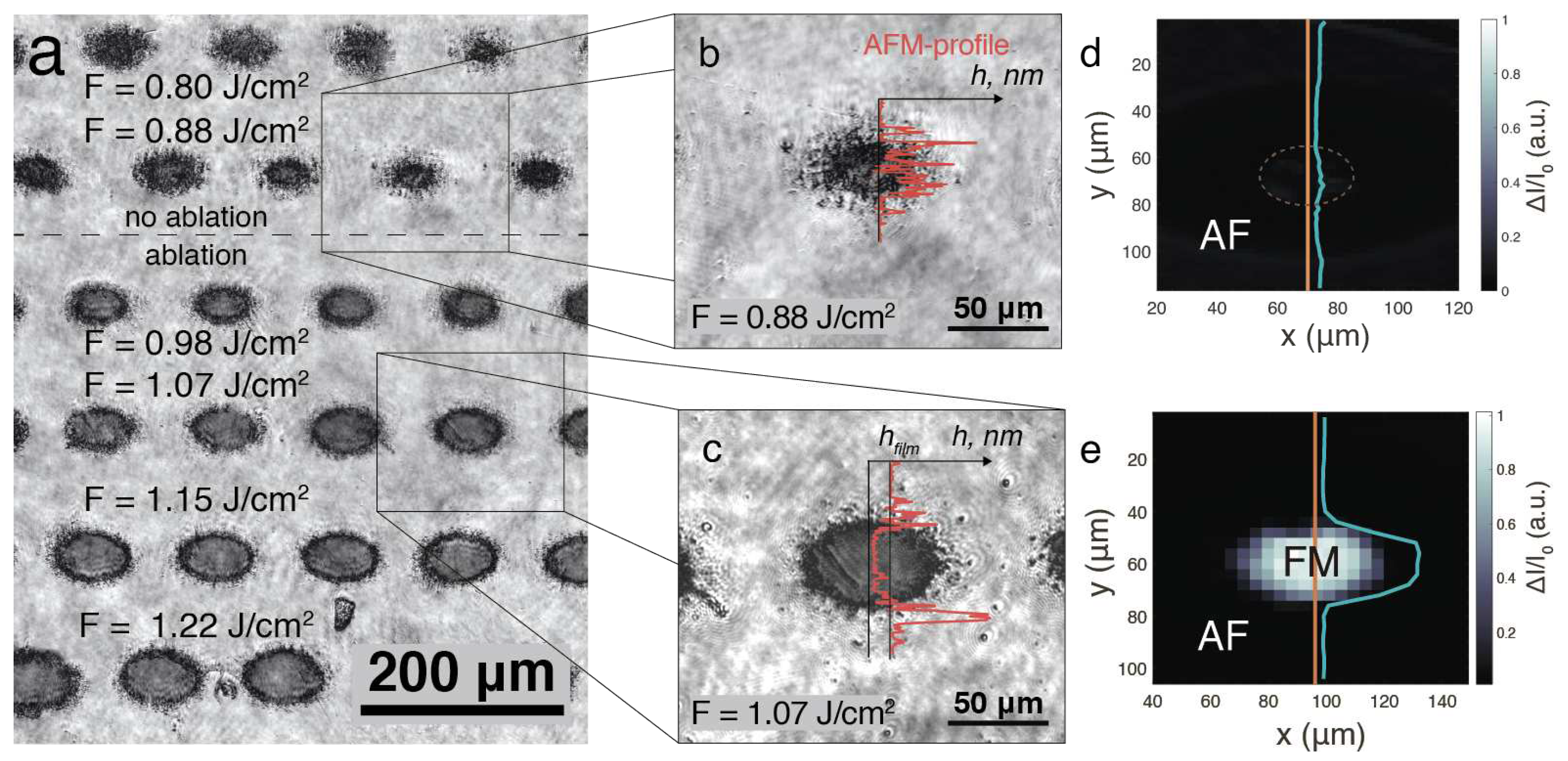
In this section, we present our findings on the magnetic properties of the FeRh structures formed after laser irradiation and discuss the processes that contribute to the results. Microphotographs of the structures created by laser irradiation revealed their morphology and dimensions (Figure 2a, b and c). Figure 2b presents a microphotograph of the structure created after irradiation by a laser pulse with a fluence of F = 0.88 J/cm 2 . At first glance, this structure appears as a dark, elliptical blotch on the original film, with diameters of 20 and 30 μ m, fringed by residual remnants. The red curve in Figure 2b and c represents an AFM measurement of the relief profile within the structure, providing a more intricate understanding of its morphology. According to this analysis, the dark blotch is likely a result of laser-induced material transformation or deposition on the film surface. Comparatively, the structure created at higher fluences, as demonstrated in Figure 2d, exhibits clearer and more defined boundaries. A close inspection of the relief highlights the formation of a near 45 nm crater, accompanied by residues at the film base and around the crater periphery. This observation suggests the film has undergone partial removal i.e., ablation.
Figure 2c shows the Scanning Magneto-Optical Kerr Effect (S-MOKE) map at the position previously visualized in Figure 2b. The absence of detectable signals within this map suggests that the structure retains its antiferromagnetic (AF) phase after laser irradiation. Conversely, as demonstrated in Figure 2e, a structure with material removal showcases identifiable signals within its confines, indicative of a phase transition. However, the unaltered film surrounding the ablated region displays a lack of discernible signals, implying it remains in its original phase.
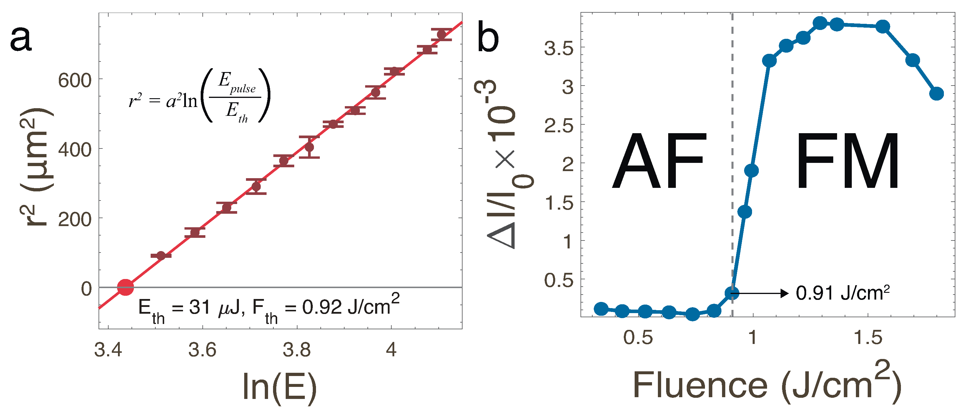
In the experiments, laser irradiation exhibiting a Gaussian intensity profile was utilized to generate the structures. A specific threshold fluence is necessary to initiate the ablation process. By employing Liu’s method [39], the Gaussian distribution parameters can be deduced from the pulse energy and dimensions of the structure. Consequently, a linear relationship between the radial size ( r 2 ) of the structure and the natural logarithm of the pulse energy is established. Figure 3a demonstrates this relationship for the structures obtained with ablation, plotting r 2 against ln( E pulse ). The intersection point of the linear relationship with the zero value represents the fluence threshold for ablation. In the case of FeRh, the threshold energy ( E th ) is (31 ± 3) μ J, and the threshold fluence ( F th ) is (0.92 ± 0.07) J/cm 2 .
Figure 2e previously depicted the spatial distribution of the magneto-optical signal within the structure. Given that the structure was produced using a laser beam with a spatial intensity distribution, the association between the magneto-optical signal and intensity can be ascertained by comparing these two distributions.
Figure 3b demonstrates the dependence of the magneto-optical signal on the laser fluence. Up to 0.91 J/cm 2 , FeRh retains its antiferromagnetic properties, exhibiting magnetization values approximating 0. Above 0.91 J/cm 2 , the magneto-optical signal experiences a rapid increase, reaching its peak value of (3.8 ± 0.4) × 10 3 between 1.2 and 1.4 J/cm 2 . Following this, a reduction to 2.9 × 10 3 occurs.
As observed in Figure 3b, the ablation threshold and the value corresponding to the phase transition from antiferromagnetic to ferromagnetic are nearly identical. This finding implies that the ablation process is the primary factor responsible for the magnetic phase transition observed in FeRh.
To investigate the effect of temperature changes on the magneto-optical properties, we modified our experimental setup by incorporating an additional CW-laser from the back side of the sample during magneto-optical signal measurements (Figure 4a). This CW-laser, with a wavelength of around 450 nm, was focused into a 150 μ m spot. By adjusting the power of the laser, the temperature of the sample could be altered, enabling the acquisition of magneto-optical signals at the selected power levels.
Figure 4b presents the results obtained for the initial FeRh film. The lower horizontal axis represents power, while the blue curve corresponds to MOKE measured during sample heating. Magnetization appears at a power of approximately 0.5 W, increasing to a maximum value of (4.6 ± 0.4) × 10 3 before declining and approaching 0 at 2.5 W. This behavior is consistent with the well-known FeRh phase diagram [17] and represents a consequent AF-FM and FM-PM phase transitions observed in B2-ordered FeRh [18]. Based on tests conducted on the samples post-preparation, the AF-FM phase transition occurs at 370 K, while the FM-PM phase transition is reached at 640 K. With this information, the power scale can be converted to a temperature scale, as displayed on the upper vertical axis of Figure 4b.
Following the heating of the sample to a power of 2.5 W, measurements have been continued as the power has been reduced i.e. the sample was cooled. Between 2.5 W and 0.6 W, or from 650 K to 390 K, the magnetization was increasing on the same trajectory, when was decreasing under heating. However, in the temperature range of 390 K to 360 K, magnetization exhibited a continuous increase, followed by a rapid decline after reaching its maximum value, i.e. performing the hysteresis. The magnetization eventually approached zero at approximately 350 K. This observed behavior aligns with previously reported FeRh characteristics described in the literature [18,40,41].
After examining the initial film, we turned our attention to the structures created through laser irradiation. First, we carried out a spatial scan at room temperature once again, with the results shown in Figure 5b for a structure obtained at F = 1.8 J/cm 2 . Following the measurements, only the surrounding area displayed the FM phase, with a width between 8 and 16 μ m. No ferromagnetic properties were evident in the center of the ablated structure compared to the case before the heating of the initial film Figure 5a, a trend consistent across all structures.
Subsequently, we conducted a scan along the horizontal line in the center of the structure (indicated by the red line in Figure 5b), changing the temperature at each point. Figure 5c presents the resulting data. The curved shapes of the areas can be attributed to the movement of the sample due to the applied temperature. During the temperature change, a drastic increase in magnetization was observed starting from 370 K (0.6 W), suggesting the antiferromagnetic (AF) to ferromagnetic (FM) phase transition for the untreated FeRh.
Notably, no variation in the TMOKE signal with temperature was observed inside the ablated structure. Consequently, the magnetization behavior of the laser-produced structures does not exhibit the same reversibility as the initial film.
The correlation of the observed threshold in S-MOKE measurements with the ablation threshold invites to speculate about its physical origin. Dynamics studies of femtosecond laser ablation have clearly demonstrated that in its initial phase the film is separated by an optically thick shell of laser-melted material moving away from the surface and existing on nanosecond time scales [42,43], an effect confirmed by theoretical simulations [44]. This means that the remaining part of the material is protected from the contact with ambient atmosphere (and thus, oxidation and photo-chemistry in the liquid phase) for at least few nanoseconds. A FM behaviour of ablated region (Figure 2e) might be a result of combined effect of chemical disorder and strain. The sensitivity of the observed MOKE signal to the thermal annealing of the sample performed using CW laser at ambient conditions can be caused by oxidation effects of a thin FM layer remaining at the crater of ablated structure (Figure 2c). In contrast, the untreated area of 45 nm thick FeRh film around the ablated crater exhibits a reversible AF-FM phase transition when heated at the same conditions. A possible route for future experiments would be to create such structures using controlled thermo-mechanical femtosecond laser spallation by illuminating FeRh films through the substrate in the regime of closed spallation cavities [45]. Such experiments with partially melted and cavity-protected FeRh spieces are expected to shade light on the physical origin of ablation-induced phase transformation in FeRh film.

4. Conclusions

In summary, we have investigated the magnetic properties of FeRh thin films irradiated by single high-intensity femtosecond laser pulses in the ablation regime. Scanning MOKE (S-MOKE) microscopy was employed to study the magnetic phase after fs-laser processing, revealing the appearance of a magneto-optical signal at the bottom of the ablation crater. The dependence of the magneto-optical signal on the laser fluence demonstrates a strong correlation between the ablation process and the magnetic behavior in FeRh thin films. The transition from the antiferromagnetic to the ferromagnetic state in the laser-ablated regions has been observed, while the surrounding initial film retained its antiferromagnetic properties. CW-laser-assisted temperature-dependent measurements performed both on the initial film and the laser-created structures revealed that the magnetic properties of the structures did not display the same reversibility as the initial film. This finding suggests that laser-induced phase transitions and changes in magnetic properties in FeRh thin films are irreversible when performed under ambient conditions.

Author Contributions

Conceptualization, P.V. (Pavel Varlamov), A.S. and V.T.; methodology, O.N., P.V. (Paolo Vavassori) and V.T.; software, P.V. (Pavel Varlamov) and A.N.D.; validation, P.V. (Pavel Varlamov) and A.N.D.; formal analysis, P.V. (Pavel Varlamov); investigation, P.V. (Pavel Varlamov) and A.D.N.; resources, Y.L., M.R., M.F., O.N. and V.T.; data curation, P.V. (Pavel Varlamov); writing—original draft preparation, P.V. (Pavel Varlamov); writing—review and editing, P.V. (Pavel Varlamov), A.S., P.V. (Paolo Vavassori), and V.T.; visualization, P.V. (Pavel Varlamov); supervision, M.R., M.F., O.N., P.V. (Paolo Vavassori) and V.T.; project administration, P.V. (Paolo Vavassori) and V.T.; funding acquisition, M.R., M.F., P.V. (Paolo Vavassori) and V.T. All authors have read and agreed to the published version of the manuscript.

Acknowledgments

The support by the ANR-21-MRS1-0015-01 “IRON-MAG” is gratefully acknowledged. P.V. (Paolo Vavassori) acknowledges support from the Spanish Ministry of Science, Innovation, and Universities and the European Union under the Maria de Maeztu Units of Excellence Programme (CEX2020-001038-M) and the project RTI2018-094881-B-I00 (MICINN/FEDER).

Conflicts of Interest

The authors declare no conflict of interest.

References

  1. Crangle, J.; Goodman, G. The magnetization of pure iron and nickel. Proceedings of the Royal Society of London. A. Mathematical and Physical Sciences 1971, 321, 477–491. [Google Scholar] [CrossRef]
  2. Beaurepaire, E.; Merle, J.C.; Daunois, A.; Bigot, J.Y. Ultrafast spin dynamics in ferromagnetic nickel. Physical review letters 1996, 76, 4250. [Google Scholar] [CrossRef]
  3. Van Kampen, M.; Jozsa, C.; Kohlhepp, J.; LeClair, P.; Lagae, L.; De Jonge, W.; Koopmans, B. All-optical probe of coherent spin waves. Physical review letters 2002, 88, 227201. [Google Scholar] [CrossRef]
  4. Bigot, J.Y.; Vomir, M.; Andrade, L.; Beaurepaire, E. Ultrafast magnetization dynamics in ferromagnetic cobalt: The role of the anisotropy. Chemical physics 2005, 318, 137–146. [Google Scholar] [CrossRef]
  5. Salikhov, R.; Alekhin, A.; Parpiiev, T.; Pezeril, T.; Makarov, D.; Abrudan, R.; Meckenstock, R.; Radu, F.; Farle, M.; Zabel, H.; others. Gilbert damping in NiFeGd compounds: Ferromagnetic resonance versus time-resolved spectroscopy. Physical Review B 2019, 99, 104412. [Google Scholar] [CrossRef]
  6. Scherbakov, A.; Salasyuk, A.; Akimov, A.; Liu, X.; Bombeck, M.; Brüggemann, C.; Yakovlev, D.; Sapega, V.; Furdyna, J.; Bayer, M. Coherent magnetization precession in ferromagnetic (Ga, Mn) As induced by picosecond acoustic pulses. Physical review letters 2010, 105, 117204. [Google Scholar] [CrossRef]
  7. Kim, J.W.; Vomir, M.; Bigot, J.Y. Ultrafast magnetoacoustics in nickel films. Physical review letters 2012, 109, 166601. [Google Scholar] [CrossRef]
  8. Vlasov, V.; Golov, A.; Kotov, L.; Shcheglov, V.; Lomonosov, A.; Temnov, V. The modern problems of ultrafast magnetoacoustics. Acoustical Physics 2022, 68, 18–47. [Google Scholar] [CrossRef]
  9. Kimel, A.; Zvezdin, A.; Sharma, S.; Shallcross, S.; De Sousa, N.; García-Martín, A.; Salvan, G.; Hamrle, J.; Stejskal, O.; McCord, J.; others. The 2022 magneto-optics roadmap. Journal of Physics D: Applied Physics 2022, 55, 463003. [Google Scholar] [CrossRef]
  10. Kisielewski, J.; Kurant, Z.; Sveklo, I.; Tekielak, M.; Wawro, A.; Maziewski, A. Magnetic phases in Pt/Co/Pt films induced by single and multiple femtosecond laser pulses. Journal of Applied Physics 2016, 119, 193901. [Google Scholar] [CrossRef]
  11. Urner-Wille, M.; Kobs, R.; Witter, K. Picosecond laser-induced change of the magnetic properties of amorphous GdFeBi-films. IEEE Transactions on Magnetics 1981, 17, 2621–2623. [Google Scholar] [CrossRef]
  12. Ehrler, J.; He, M.; Shugaev, M.V.; Polushkin, N.I.; Wintz, S.; Liersch, V.; Cornelius, S.; Hubner, R.; Potzger, K.; Lindner, J.; others. Laser-rewriteable ferromagnetism at thin-film surfaces. ACS applied materials & interfaces 2018, 10, 15232–15239. [Google Scholar] [CrossRef]
  13. Polushkin, N.I.; Oliveira, V.; Vilar, R.; He, M.; Shugaev, M.; Zhigilei, L. Phase-change magnetic memory: Rewritable ferromagnetism by laser quenching of chemical disorder in Fe 60 Al 40 alloy. Physical Review Applied 2018, 10, 024023. [Google Scholar]
  14. Stanciu, C.D.; Hansteen, F.; Kimel, A.V.; Kirilyuk, A.; Tsukamoto, A.; Itoh, A.; Rasing, T. All-optical magnetic recording with circularly polarized light. Physical review letters 2007, 99, 047601. [Google Scholar] [CrossRef]
  15. Vahaplar, K.; Kalashnikova, A.; Kimel, A.; Gerlach, S.; Hinzke, D.; Nowak, U.; Chantrell, R.; Tsukamoto, A.; Itoh, A.; Kirilyuk, A.; others. All-optical magnetization reversal by circularly polarized laser pulses: Experiment and multiscale modeling. Physical review B 2012, 85, 104402. [Google Scholar] [CrossRef]
  16. Ostler, T.; Barker, J.; Evans, R.; Chantrell, R.; Atxitia, U.; Chubykalo-Fesenko, O.; El Moussaoui, S.; Le Guyader, L.; Mengotti, E.; Heyderman, L.; others. Ultrafast heating as a sufficient stimulus for magnetization reversal in a ferrimagnet. Nature communications 2012, 3, 666. [Google Scholar] [CrossRef]
  17. Lewis, L.; Marrows, C.; Langridge, S. Coupled magnetic, structural, and electronic phase transitions in FeRh. Journal of Physics D: Applied Physics 2016, 49, 323002. [Google Scholar] [CrossRef]
  18. Heidarian, A.; Stienen, S.; Semisalova, A.; Yuan, Y.; Josten, E.; Hübner, R.; Salamon, S.; Wende, H.; Gallardo, R.; Grenzer, J.; others. Ferromagnetic resonance of MBE-grown FeRh thin films through the metamagnetic phase transition. physica status solidi (b) 2017, 254, 1700145. [Google Scholar] [CrossRef]
  19. Eggert, B.; Schmeink, A.; Lill, J.; Liedke, M.O.; Kentsch, U.; Butterling, M.; Wagner, A.; Pascarelli, S.; Potzger, K.; Lindner, J.; others. Magnetic response of FeRh to static and dynamic disorder. RSC advances 2020, 10, 14386–14395. [Google Scholar] [CrossRef]
  20. Vogler, C.; Abert, C.; Bruckner, F.; Suess, D. Noise Reduction Based on an Fe- Rh Interlayer in Exchange-Coupled Heat-Assisted Recording Media. Physical Review Applied 2017, 8, 054021. [Google Scholar] [CrossRef]
  21. Feng, Z.; Yan, H.; Liu, Z. Electric-Field Control of Magnetic Order: From FeRh to Topological Antiferromagnetic Spintronics. Advanced Electronic Materials 2019, 5, 1800466. [Google Scholar] [CrossRef]
  22. Qiao, K.; Liang, Y.; Zhang, H.; Hu, F.; Yu, Z.; Long, Y.; Wang, J.; Sun, J.; Zhao, T.; Shen, B. Manipulation of magnetocaloric effect in FeRh films by epitaxial growth. Journal of Alloys and Compounds 2022, 907, 164574. [Google Scholar] [CrossRef]
  23. Vieira, R.M.; Eriksson, O.; Bergman, A.; Herper, H.C. High-throughput compatible approach for entropy estimation in magnetocaloric materials: FeRh as a test case. Journal of Alloys and Compounds 2021, 857, 157811. [Google Scholar] [CrossRef]
  24. Chirkova, A.; Skokov, K.; Schultz, L.; Baranov, N.; Gutfleisch, O.; Woodcock, T. Giant adiabatic temperature change in FeRh alloys evidenced by direct measurements under cyclic conditions. Acta Materialia 2016, 106, 15–21. [Google Scholar] [CrossRef]
  25. Bennett, S.; Ambaye, H.; Lee, H.; LeClair, P.; Mankey, G.; Lauter, V. Direct evidence of anomalous interfacial magnetization in metamagnetic Pd doped FeRh thin films. Scientific Reports 2015, 5, 9142. [Google Scholar] [CrossRef]
  26. Hu, Q.; Li, J.; Wang, C.; Zhou, Z.; Cao, Q.; Zhou, T.; Wang, D.; Du, Y. Electric field tuning of magnetocaloric effect in FeRh0. 96Pd0. 04/PMN-PT composite near room temperature. Applied Physics Letters 2017, 110, 222408. [Google Scholar] [CrossRef]
  27. Barua, R.; Jiménez-Villacorta, F.; Lewis, L. Predicting magnetostructural trends in FeRh-based ternary systems. Applied Physics Letters 2013, 103, 102407. [Google Scholar] [CrossRef]
  28. Urban, C.; Bennett, S.P.; Schuller, I.K. Hydrostatic pressure mapping of barium titanate phase transitions with quenched FeRh. Scientific reports 2020, 10, 6312. [Google Scholar] [CrossRef]
  29. Fujita, N.; Matsui, T.; Kosugi, S.; Satoh, T.; Saitoh, Y.; Takano, K.; Koka, M.; Kamiya, T.; Seki, S.; Iwase, A. Micrometer-sized magnetic patterning of FeRh films using an energetic ion microbeam. Japanese Journal of Applied Physics 2010, 49, 060211. [Google Scholar] [CrossRef]
  30. Koide, T.; Satoh, T.; Kohka, M.; Saitoh, Y.; Kamiya, T.; Ohkouchi, T.; Kotsugi, M.; Kinoshita, T.; Nakamura, T.; Iwase, A.; others. Magnetic patterning of FeRh thin films by energetic light ion microbeam irradiation. Japanese Journal of Applied Physics 2014, 53, 05FC06. [Google Scholar] [CrossRef]
  31. Heidarian, A.; Bali, R.; Grenzer, J.; Wilhelm, R.; Heller, R.; Yildirim, O.; Lindner, J.; Potzger, K. Tuning the antiferromagnetic to ferromagnetic phase transition in FeRh thin films by means of low-energy/low fluence ion irradiation. Nuclear Instruments and Methods in Physics Research Section B: Beam Interactions with Materials and Atoms 2015, 358, 251–254. [Google Scholar] [CrossRef]
  32. Bennett, S.; Herklotz, A.; Cress, C.; Ievlev, A.; Rouleau, C.; Mazin, I.; Lauter, V. Magnetic order multilayering in FeRh thin films by He-Ion irradiation. Materials Research Letters 2018, 6, 106–112. [Google Scholar] [CrossRef]
  33. Cress, C.D.; Wickramaratne, D.; Rosenberger, M.R.; Hennighausen, Z.; Callahan, P.G.; LaGasse, S.W.; Bernstein, N.; van ’t Erve, O.M.; Jonker, B.T.; Qadri, S.B.; Prestigiacomo, J.C.; Currie, M.; Mazin, I.I.; Bennett, S.P. Direct-Write of Nanoscale Domains with Tunable Metamagnetic Order in FeRh Thin Films. ACS Applied Materials & Interfaces 2021, 13, 836–847. [Google Scholar] [CrossRef]
  34. Ju, G.; Hohlfeld, J.; Bergman, B.; van de Veerdonk, R.J.; Mryasov, O.N.; Kim, J.Y.; Wu, X.; Weller, D.; Koopmans, B. Ultrafast generation of ferromagnetic order via a laser-induced phase transformation in FeRh thin films. Physical review letters 2004, 93, 197403. [Google Scholar] [CrossRef]
  35. Bergman, B.; Ju, G.; Hohlfeld, J.; van de Veerdonk, R.J.; Kim, J.Y.; Wu, X.; Weller, D.; Koopmans, B. Identifying growth mechanisms for laser-induced magnetization in FeRh. Physical Review B 2006, 73, 060407. [Google Scholar] [CrossRef]
  36. Pressacco, F.; Uhlíř, V.; Gatti, M.; Nicolaou, A.; Bendounan, A.; Arregi, J.A.; Patel, S.K.; Fullerton, E.E.; Krizmancic, D.; Sirotti, F. Laser induced phase transition in epitaxial FeRh layers studied by pump-probe valence band photoemission. Structural Dynamics 2018, 5, 034501. [Google Scholar] [CrossRef]
  37. Awari, N.; Semisalova, A.; Deinert, J.C.; Lenz, K.; Lindner, J.; Fullerton, E.; Uhlíř, V.; Li, J.; Clemens, B.; Carley, R.; others. Monitoring laser-induced magnetization in FeRh by transient terahertz emission spectroscopy. Applied Physics Letters 2020, 117, 122407. [Google Scholar] [CrossRef]
  38. Temnov, V.V.; Armelles, G.; Woggon, U.; Guzatov, D.; Cebollada, A.; Garcia-Martin, A.; Garcia-Martin, J.M.; Thomay, T.; Leitenstorfer, A.; Bratschitsch, R. Active magneto-plasmonics in hybrid metal–ferromagnet structures. Nature Photonics 2010, 4, 107–111. [Google Scholar] [CrossRef]
  39. Liu, J.M. Simple technique for measurements of pulsed Gaussian-beam spot sizes. Optics letters 1982, 7, 196–198. [Google Scholar] [CrossRef]
  40. Dróżdż, P.; Ślęzak, M.; Matlak, K.; Kozioł-Rachwał, A.; Korecki, J.; Slezak, T. Spin-flop coupling induced large coercivity enhancement in Fe/FeRh/W(110) bilayers across ferromagnetic–antiferromagnetic phase transition of FeRh alloy. Journal of Magnetism and Magnetic Materials 2019, 498, 166258. [Google Scholar] [CrossRef]
  41. Xie, Y.; Zhan, Q.; Shang, T.; Yang, H.; Liu, Y.; Wang, B.; Li, R.W. Electric field control of magnetic properties in FeRh/PMN-PT heterostructures. AIP Advances 2018, 8, 055816. [Google Scholar] [CrossRef]
  42. Sokolowski-Tinten, K.; Bialkowski, J.; Cavalleri, A.; von der Linde, D.; Oparin, A.; Meyer-ter Vehn, J.; Anisimov, S. Transient states of matter during short pulse laser ablation. Physical Review Letters 1998, 81, 224. [Google Scholar] [CrossRef]
  43. Temnov, V.V.; Sokolowski-Tinten, K.; Zhou, P.; von der Linde, D. Ultrafast imaging interferometry at femtosecond-laser-excited surfaces. JOSA B 2006, 23, 1954–1964. [Google Scholar] [CrossRef]
  44. Ivanov, D.S.; Zhigilei, L.V. Combined atomistic-continuum modeling of short-pulse laser melting and disintegration of metal films. Physical Review B 2003, 68, 064114. [Google Scholar] [CrossRef]
  45. Temnov, V.V.; Alekhin, A.; Samokhvalov, A.; Ivanov, D.S.; Lomonosov, A.; Vavassori, P.; Modin, E.; Veiko, V.P. Nondestructive femtosecond laser lithography of Ni nanocavities by controlled thermo-mechanical spallation at the nanoscale. Nano Letters 2020, 20, 7912–7918. [Google Scholar] [CrossRef]
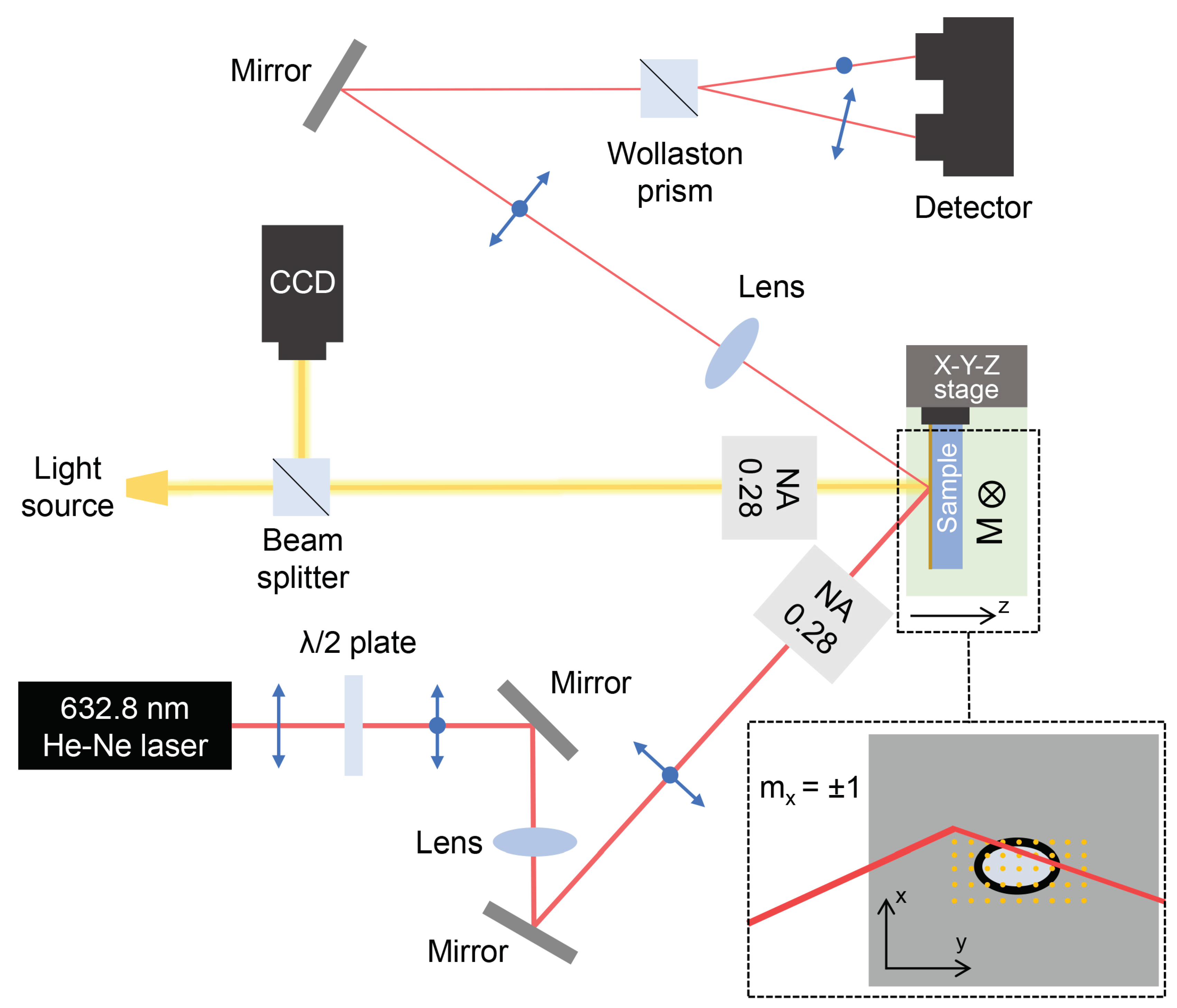
Figure 1. Schematics of the setup for the S-MOKE microscopy in the transversal MOKE configuration with balanced photodetection using polarized light.
Preprints 77175 g001
Figure 2. The microscopic pictures of the fs-laser produced structures: (a) Optical microscopy of the obtained structures under F in a range from 0.8 to 1.25 J / c m 2 . (b) Optical microscopy of the structure obtained by the pulse with (b) F = 0.88 J/cm 2 and (c) F = 1.07 J/cm 2 . The red curve corresponds to the topographic image measured with AFM. h f i l m corresponds to the thickness of the film (45 nm). (d) S-MOKE pictures for the structures produced at the (d) F = 0.88 J/cm 2 and (e) F = 1.07 J/cm 2 . The turquoise curve describes the spatial distribution of the MOKE signals obtained in the center, along the orange line. AF stands for antiferromagnetic, FM - ferromagnetic.
Preprints 77175 g002
Figure 3. (a) Squared radius of the ablation-induced structure dependence on the natural logarithm of energy pulse (E p u l s e ). The intersection with the line y = 0 of the linear fit allows to find the threshold energy (E t h ) and threshold fluence (F t h ) as well according to the inserted formula [39]. (b) TMOKE dependence on the fluence evaluated from the maps for each structure. The lines are to guide the eye along data points
Preprints 77175 g003
Figure 4. (a) The schematics of the measurements under additional heating from the back side of the film with additional CW-laser (b) The results of the measurements under heating for untreated FeRh. The blue curve demonstrates the magnetic behavior during the heating phase, with increasing laser power resulting in increased film temperature, up to around 600 K (2.5 W). Upon reversing the heating process, measurements exhibit a steady response until a critical range of 360-370 K (0.6 W) is reached, at which point the red trajectory becomes descriptive of the observed behavior.
Preprints 77175 g004
Figure 5. (b) S-MOKE picture taken on a structure obtained at F = 1.8 J/cm 2 at room temperature after the heating with CW-laser to T>600 K at ambient conditions. (c) The S-MOKE picture of measurements taken along the red line from the left picture with changing the power of the heating laser (temperature) at every point.
Preprints 77175 g005
Disclaimer/Publisher’s Note: The statements, opinions and data contained in all publications are solely those of the individual author(s) and contributor(s) and not of MDPI and/or the editor(s). MDPI and/or the editor(s) disclaim responsibility for any injury to people or property resulting from any ideas, methods, instructions or products referred to in the content.
Copyright: This open access article is published under a Creative Commons CC BY 4.0 license, which permit the free download, distribution, and reuse, provided that the author and preprint are cited in any reuse.
Prerpints.org logo

Preprints.org is a free preprint server supported by MDPI in Basel, Switzerland.

Subscribe

© 2024 MDPI (Basel, Switzerland) unless otherwise stated